9 minute read
Design Proposal
SITE SELECTION
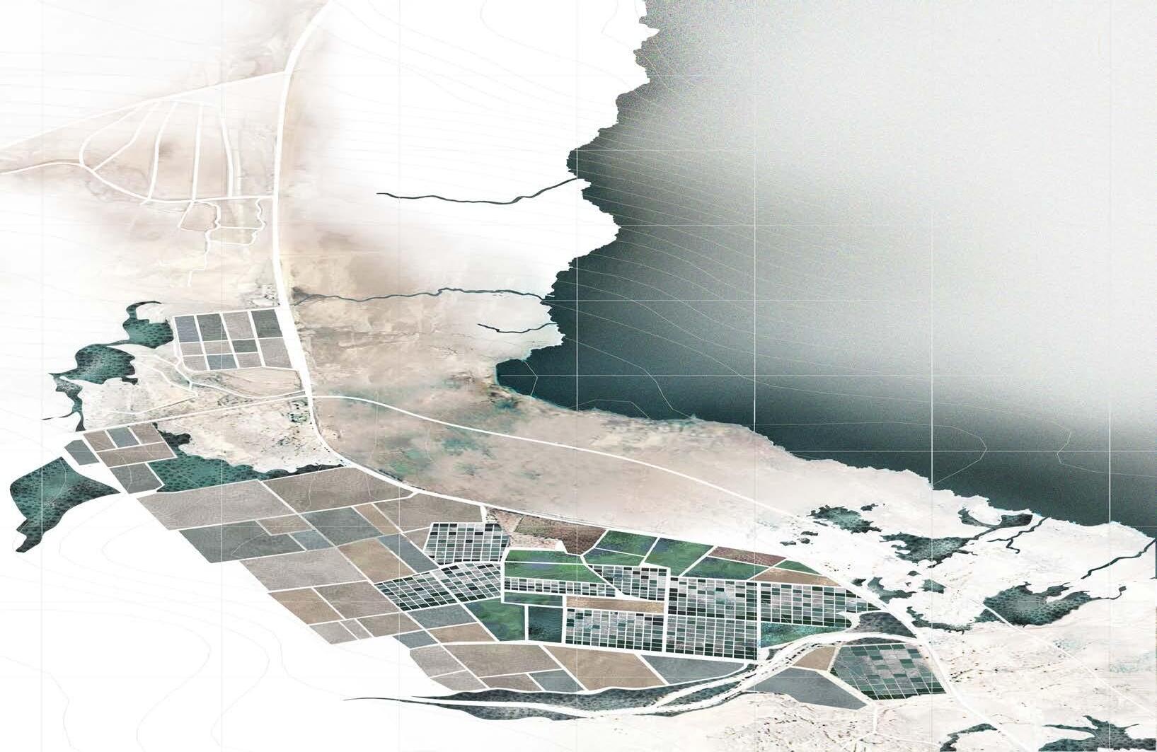
The site chosen for construction in the hyper-saline Dead Sea region is along the banks of the Northern Pool. Located on the eastern boundary of Israel, the site chosen is rich in Salt. Adding to its advantages, here salt is available in various forms. It is available both as salt crystals and as brine aiding both Rapid and Slow Prototyping techniques which combine to form the system.
Advertisement
Due to the abundance of brine available on site, the brine can also be harvested through the construction of salt evaporation ponds or salterns. The salt crystals gathered can be used for the material mix which forms the primary structure fabricated through three dimensional spatial printing using a robotic arm. The brine also aids the diachronic growth of crystals through natural evaporation.
Understanding the characteristics of Dead sea region and the properties and advantages of salt as building material, an Experimental community is proposed. This architectural proposal is along the lines of “ Acrosanti” by Paulo Soleri, a community built over time by volunteers[1]. The community provides various mixed-use buildings and public spaces where people live, work, visit, and participate in educational and cultural programs. The space hosts a large number of visitors each year.
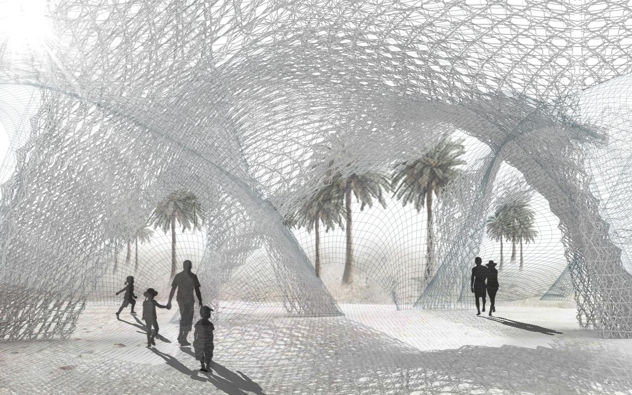
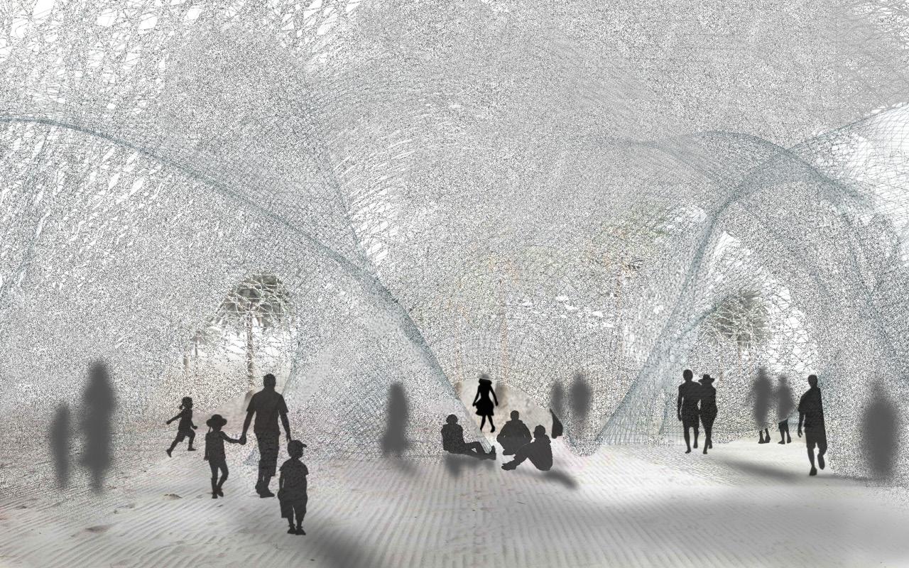
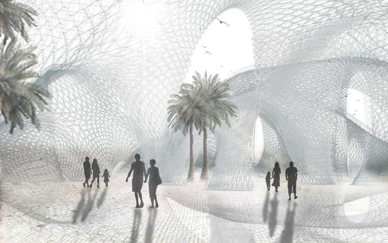
Similarly, in accordance to the user types, an experimental community is proposed, where the material which is abundantly available on site is celebrated and used by several user groups for innovation, design, health and tourism, developed over a period of time. Here the material is locally sourced and harvested and used for the construction of permanent, temporary and adaptable event spaces. The dynamics and the quality of the spaces are ever changing owing to the crystallization process which is indeterminate but proves to create surreal environments.
End Notes

[1] Arcosanti.org. (2017). Welcome arcosanti.org. [online] Available at: https://arcosanti.org/
Environmental Analysis
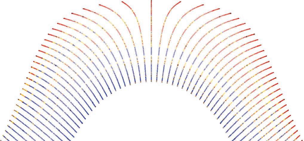
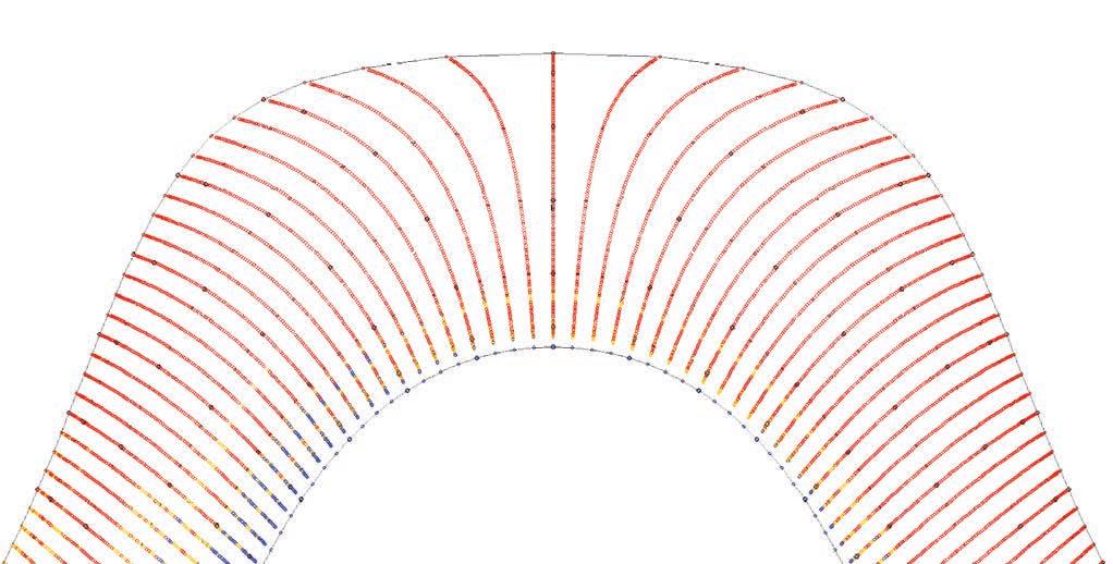
The environmental conditions of the Dead Sea region are analyzed using weather data. Temperature graphs are generated by “Mateonorm” software which provides irradiation data and other weather data for the site and shading graphs are generated by “Climate consultant” a graphicbased computer program that helps understand the local climate. The environmental conditions are studied and suggestions for design are derived through understanding the needs.
The temperature graphs show that the site has year round sunny sky conditions with high solar radiation rate and high temperatures during the summer. The design needs to respond to these conditions so that the dry bulb temperature remains within the comfort zone. This can be accomplished by adding design features such a self-shading. The colour of the material developed also provides high albedo aiding local cooling.
The Solar shading chart shows sun’s bearing (along the bottom) and altitude (vertically) for every 15 minutes during the year in coloured dots. The three coloured dots yellow red and blue indicate comfort conditions when the Dry Bulb temperature is within the comfort zone, red dots indicate overheat conditions when the Dry Bulb temperature is above the top of the comfort range. Blue dots indicate under heat conditions when dry bulb temperatures are below the bottom of the comfort zone. This shows that the shading systems must be adaptable for both winter and summer seasons.
Some design suggestions through environmental analysis are:
1. Year round sunny sky conditions with high solar radiation rate and high temperature during summer - Adaptable system -natural ventilation and shading systems.
2. Wind is mostly from north-east direction. The openings shall be oriented to the prevailing breezes to facilitate cross-ventilation. Larger openings facing up-wind.
3. Orientation - North-South Direction - lesser openings / more shaded on east west orientation to minimize overheating.
RESOURCE EFFICIENCY 06.2.1.
Reusability of the material
The dearth of resources and the demand to reduce environmental impacts both in the procurement and processing of materials and products in construction places great significance on Resource Efficiency in the construction industry. This requires appreciable improvements in resource efficiency[1] Resource efficiency means using the Earth’s limited resources in a sustainable manner while minimizing impacts on the environment.
In this research, the material developed is a mixture of salt and starch both naturally occurring and derived from nature providing alternate methods of building and living. This material further has a high potential of being reused or recycled. The set material can be pulverized and mixed with determined quantities of water to produce the initial form of the material which is used for three dimensional printing.
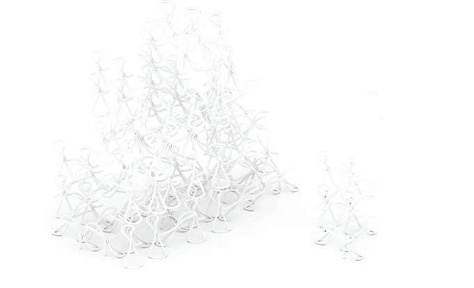
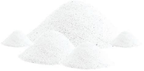
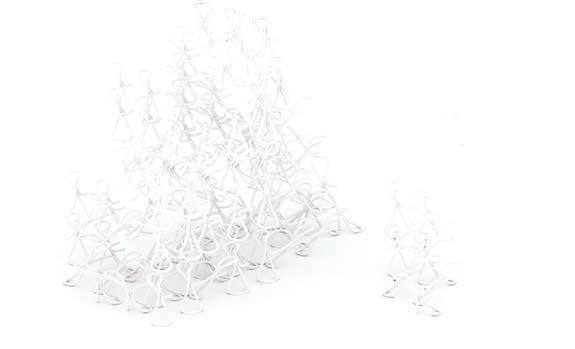
The re-use of the material involves little processing and offers greater value than recycling as there are no environmental impacts here associated with reprocessing. Therefore allowing to create more with less.
End Notes
[1] Ec.europa.eu. (2017). Resource Efficiency - Environment European Commission. [online] Available at: http:// ec.europa.eu/environment/resource_efficiency/index_en.html.
As two disparate processes are used in this research to form the architecture the staging logic becomes cardinal. The construction process is divided into two main stages;
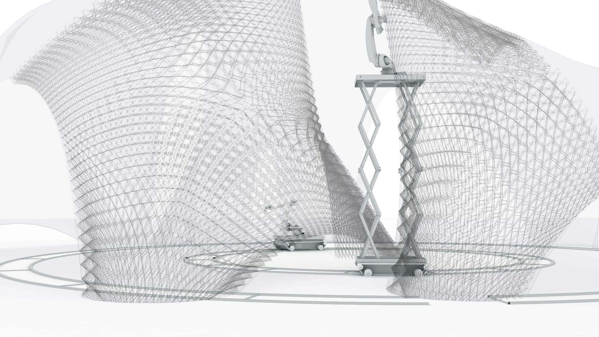
Stage 01 involves the Rapid prototyping technique of 3d extrusion printing where the main structural lattice framework is constructed by a robotic arm guided on a rail system. The robots collaborate during the printing process. The master and slave system may be used in construction process. This hierarchy is based on the sequence of tasks to be completed. The Slave robotic arm comes to play only after the Master has finished its task of printing a certain part of the structure. The slave helps with the printing of support structures providing enough time for the printed material to cure and carry the additional printed structure.
Stage 02 involves the Slow Prototyping technique of crystallization, where the building envelope is created by the accumulation or growth of salt crystals over a period of time. Here the primary structure created by 3d printing is introduced to sprays of saline solution which through nucleation by natural evaporation forms crystals that emerge to form surfaces over the lattice structure. The saline sprays are introduced through a sprinkler system, through which the frequency of spays and the amount sprayed can be manipulated as desired on different parts of the structure to create different spatial qualities depending on its function or program. An intermediate stage of waterproofing with epoxy is maybe added for the permanent spaces to prevent the primary structure from absorbing the moisture from the saline sprays during stage 02.
Salt Harvesting Process
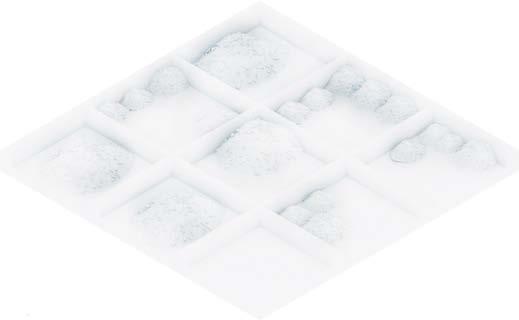
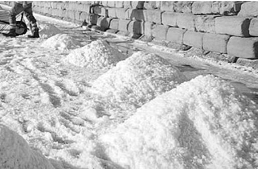
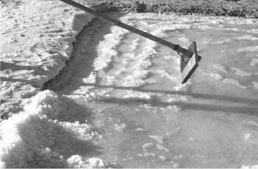

In order to be able to locally harvest the salt to use as the building material for construction, it is necessary to create facilities for harvesting these salts from brine available on site. This calls for Salt Evaporation Ponds also called Salterns are to be constructed in close proximity to the building site.
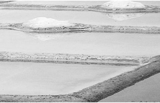
The preparation of Salterns requires a brine supply in its locale, therefore the evaporation ponds are proposed to be placed along the edges of
The the Dead Sea. This preparation also requires the subdivision of land into smaller, shallow manageable parcels into which the brine can be supplied into. The separations are made using levees, a smaller raised portion of the land regulating the water levels. The brine is then fed into these man made ponds. The water from these ponds are then let to evaporate naturally, leaving behind salt crystals that can then be gathered and harvested and used effectively for construction.

The main spatial programs required for the architectural proposal are broadly classified into private, semi-public, public and temporary spaces. The areas encompassed by the spaces are consequential to the robot placement strategies and the program requirements.
Firstly, the morphological character is set up with spaces moving from private to public. A gradient in the types of spaces is realized. The spaces are set in proximity to each other, having physical connectivity between the public and semi-public spaces while the private spaces are disconnected but are set to have visual connectivity to the public places.
Secondly, the morphological arrangement is refined in order to create interaction of spaces with their surroundings. Viewpoints and direction of views are set based on existing site conditions, existing site features and program type. This helps in creating interesting morphologies, spatial qualities and positioning open spaces.
Furthermore, distinct spatial characteristics are provided to spaces such as linking spaces, transit spaces etc. The public spaces are proposed to be well connected with high integrity and visual connection whereas; the private spaces are introverted and disconnected while spaces for temporary uses are open and flexible.
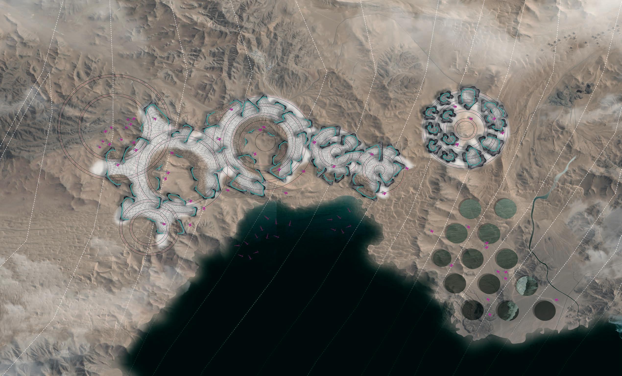

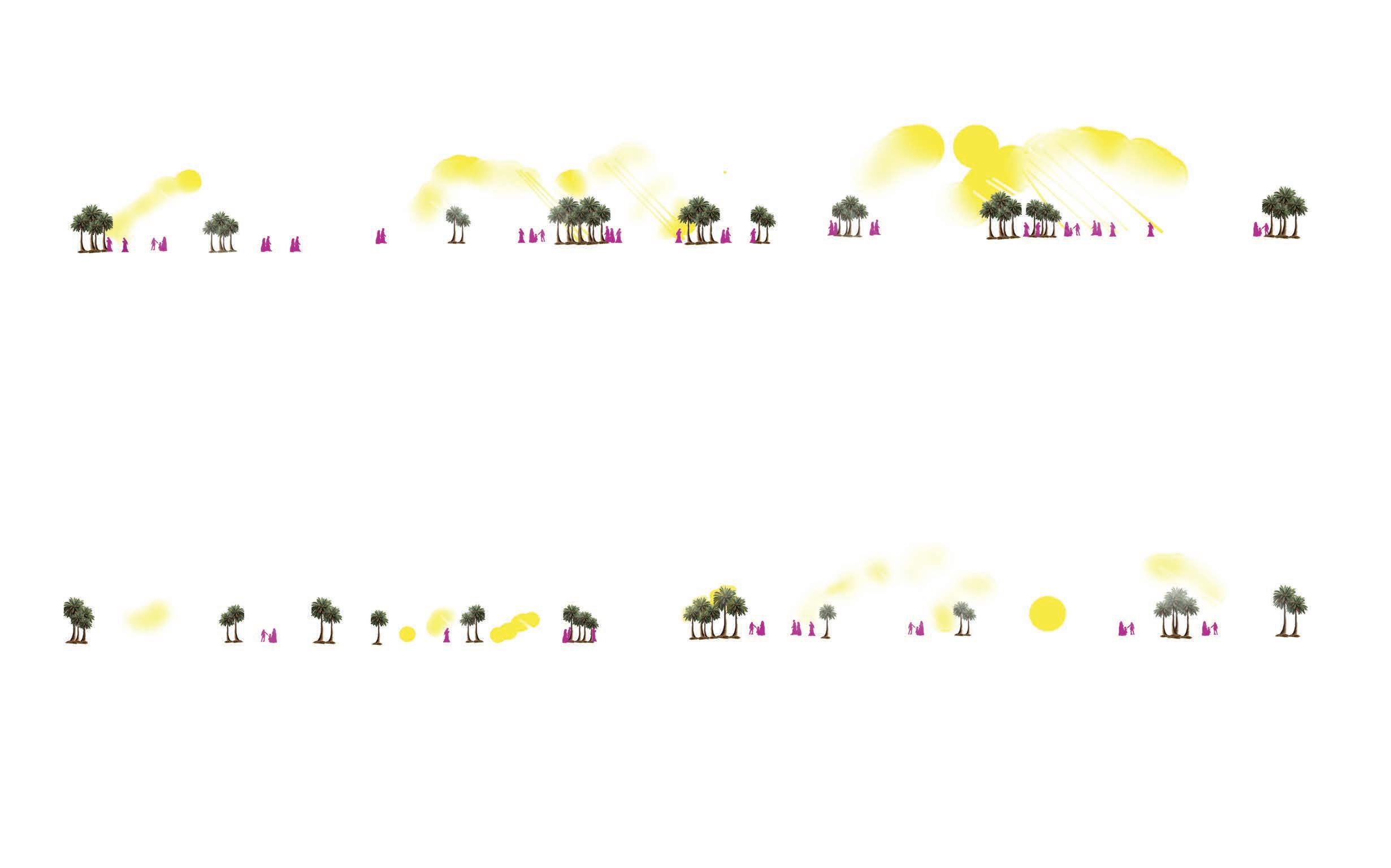

Stages of construction in the design process
Stages


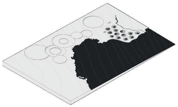
The design proposal includes a 5 stage contstruction process, from the creation of salt harvesting ponds to the construction of living spaces followed by the working and leisure and event spaces, moving from private to public.
The rails of the robot in the event spaces are proposed to be retained on site for future use and for the construction of temporary event spaces.
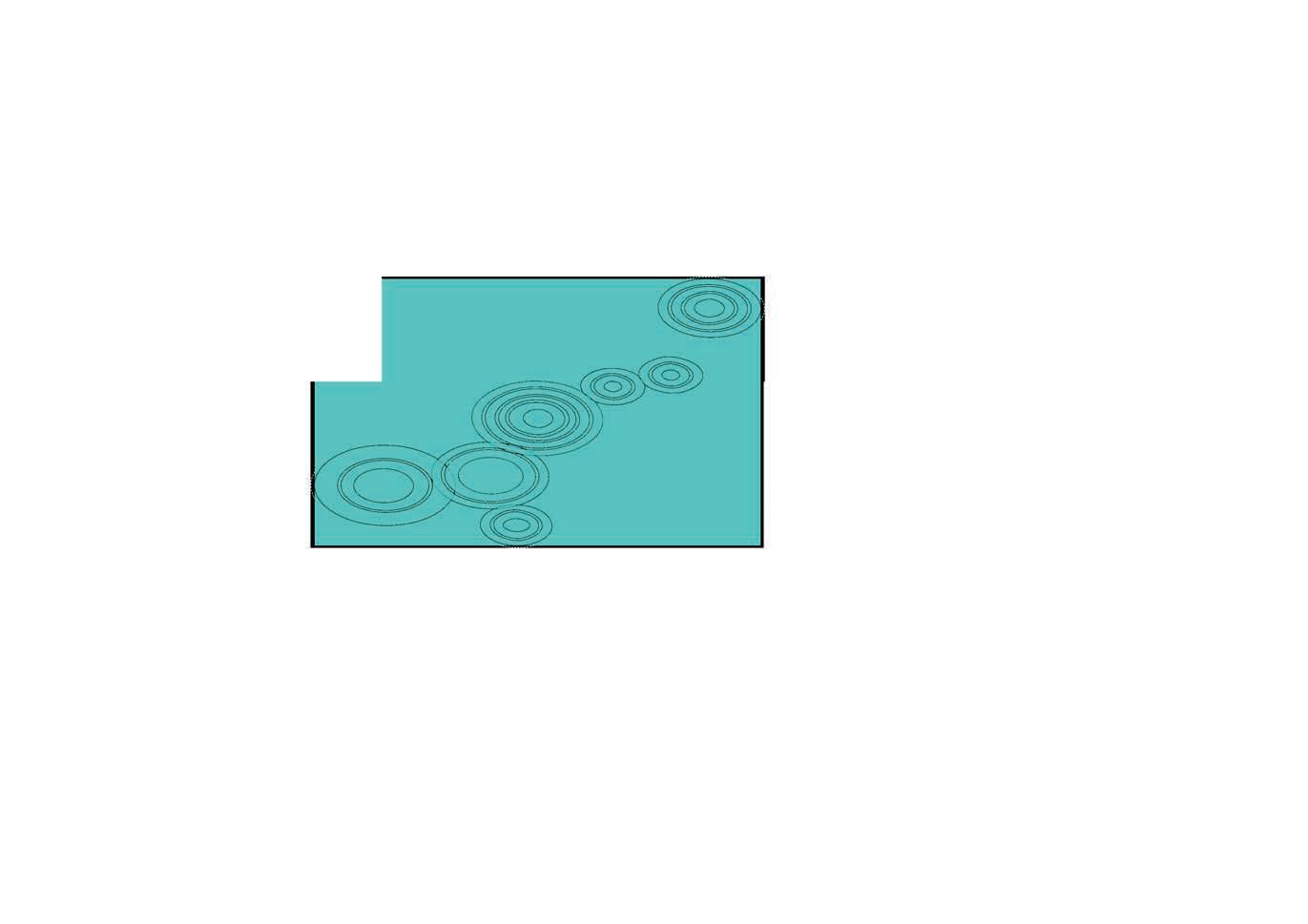
The figure above illustrates the stages of construction and figure (fig06.12) illustrates the construction process. Showing in layers the sequence in which construction process is proposed to take place.
06.3.6.
PHASING - FABRICATION PROCESS
As multiple robots collaborate to fabricate the structure, it becomes necessary to phase the fabrication process. This process of phasing also allows for structurally sound fabrication.
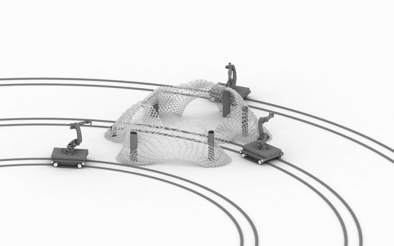
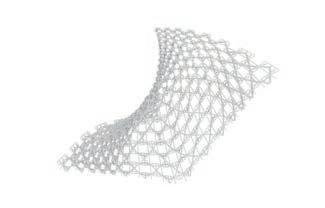
The basic subdivisioning for the phasing of the structure is illustrated in the figure (fig06.14), this allows for organized work flow, constructing bottomup providing intervals for the slave robots to print the support structures as required. The support structures are printed in a layer by layer manner and maybe removed after the fabrication and curing of the structure it supports. This process is illustrated in the figure above.
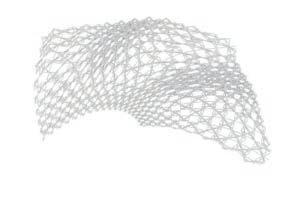
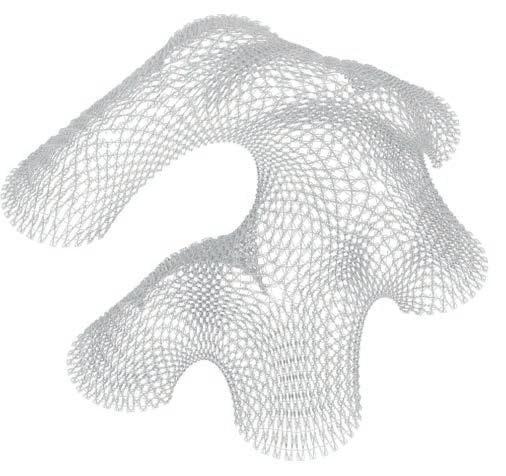
The branching system as discussed earlier determines the positioning of the robot and the number of robots invoved in the fabrication of a unit. Futhermore, the positions of the robots determine the role the robot will perform, be it a master or a slave.
STRUCTURAL ANALYSIS
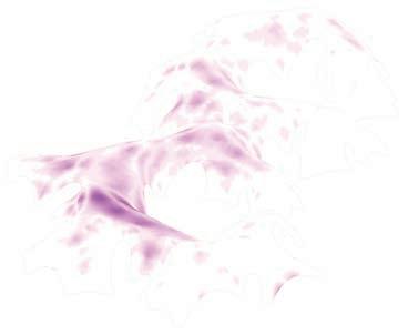
The structural performance of the geometry is analyzed using Karamba, a plug-in for Grasshopper. The aim of the analysis is to understand the maximum displacement of the 3d spatial printed structure.
The physical properties of the material are used in the analysis, the properties were determined through previous physical experiments helping to digitize the material performance. The above figure shows the principal stress lines in compression and the displacement gradient. The maximum displacement is found to be 3cm.
BUILDING RESPONSE STRATEGIES
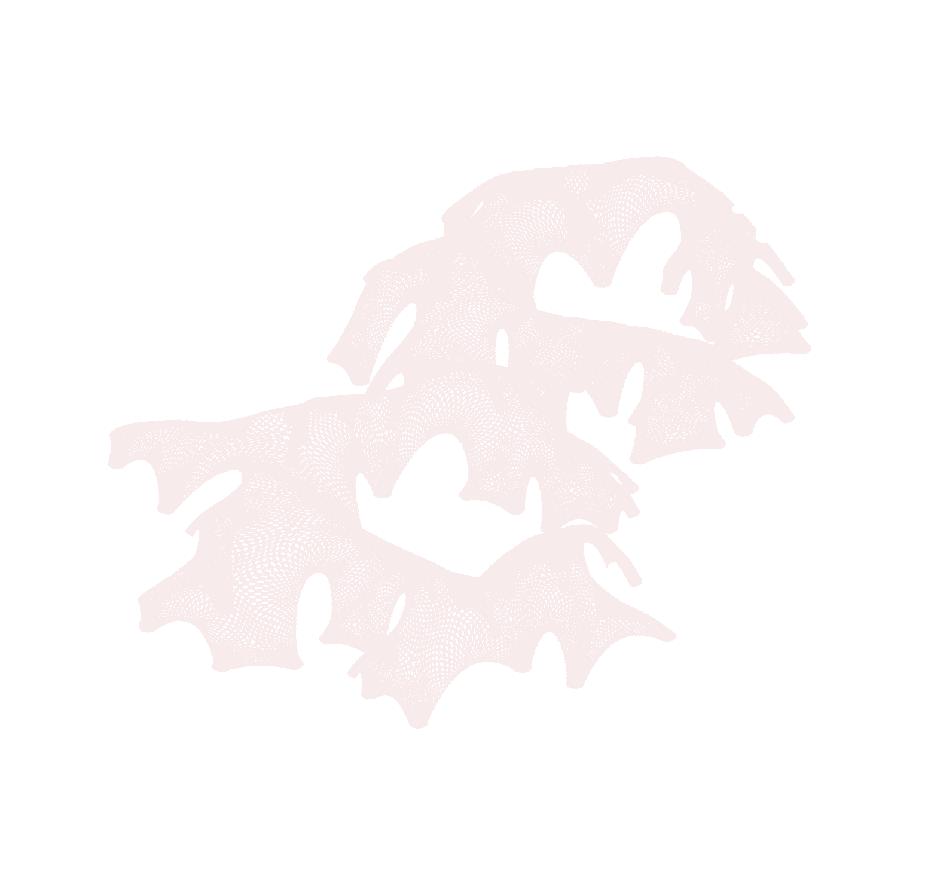
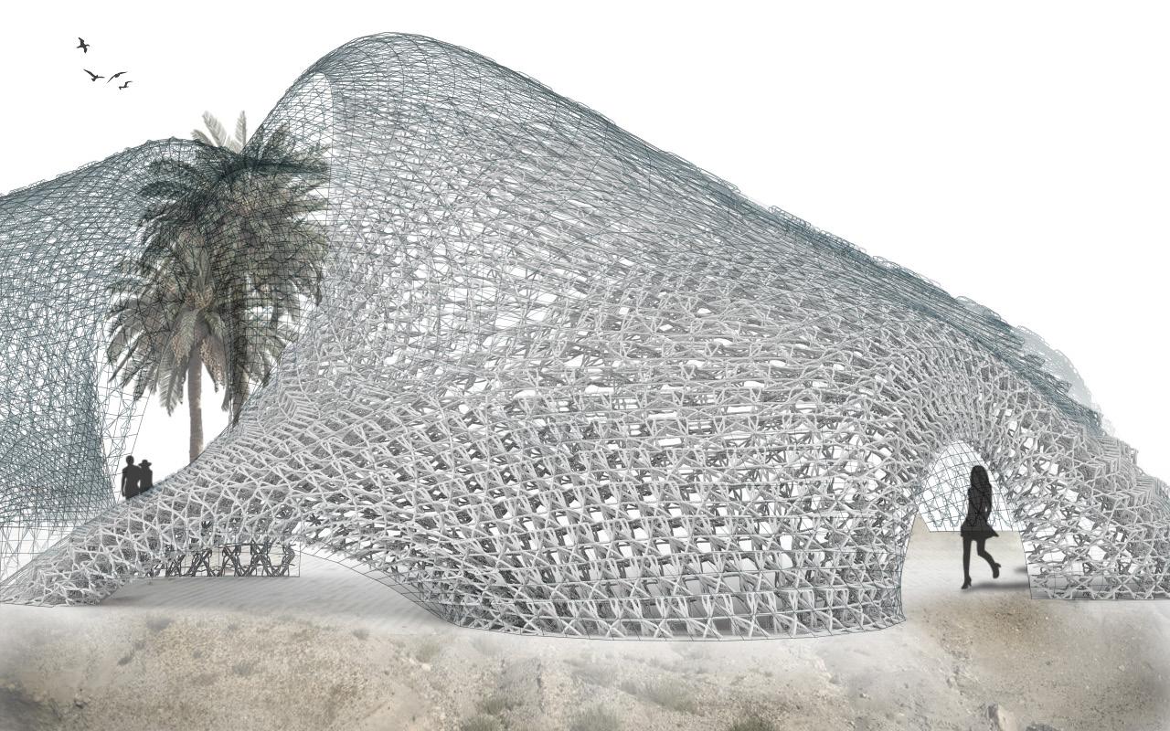
The structure is made responsive to external environmental factors. We know that the winds are predominantly from the North-East direction and from earlier environmental analysis it is understood that the best suited orientation of the structure is along the North-South direction. To aid the thermal comfort of this region, the larger openings are placed up-wind with smaller opening down-wind cooling the air as it passes through them.
Additionally, the colour of the material produces an high albedo effect thereby lowereing the temperature causing local cooling









Overview
The research approach described represents not only a systematic methodology and fabrication process, but also pushes the boundaries toward a new type of architectural frontier. An integrated computational design process embedded in the synthesis of material, form, and performance allows derivation of a complex structure which is capable of eventually producing a unique architectural typologies. These would be materially efficient and would result in a reduction of fabrication time.
In order to achieve these goals, a strong coupling is required between material properties, robotic fabrication constraints and digital design models.
C) COMPUTATIONAL PROCESS A)
The material has been explored deeply through the slow and rapid prototyping experiments. Through these experiments, we were able to assess and record the limits of the material under various conditions. The results obtained were used as a baseline to provide data for digitizing the material.
Over the course of the experiments, we faced several challenges in terms of controlling the crystallization process due to its sensitivity to the environmental condition and the mediums for the crystal growth. The results show the indeterminate nature of the diachronic growth of the salt crystals that enables constant changes in the dynamics of the spaces they enclose. Additionally, it proves to provide a unique quality of space owing to its translucent nature.
Furthermore, the data collected ensures a more comprehensive control over the material and allows for new approaches that can be explored on a micro, meso, and macro scale.
B)
As we were able to integrate the robotic constraints and material system into a design process, a new type of 3 dimensional spatial fabrication is achieved. As a result, it provided multiple options in terms of tool path exploration and form finding process. However, there are some complications regarding the autonomous process.
Firstly, manually adjusting the power of the heat guns need constant monitoring throughout fabrication process, at this stage, the monitoring is not automated. Therefore, further exploration, integration with micro controller arduino becomes important to bring the fabrication process into a fully autonomous state.
In addition to this, we must consider the calibration of the speed of the robotic arm in relation to the extrusion speed for every recharge of the material. A feedback data loop needs to be considered in order to address this. By integrating a feedback loop with a sensor to analyze the actual deformation, a real time analysis in terms of structural performance and toolpath distribution can be achieved.
Through the examination of the computational process, a complex architectural output was achieved. The integration of voxels helps simplify the overall design process, providing bounds to work with.
Due to the highly interconnected data from micro, meso, to macro scales, the resulting output required increased computation time, the process becoming computationally expensive.
For further exploration of this concept, a custom Python script would be ideal to streamline this process and address the complexity of the toolpath in conjunction with the significant number of voxels. In addition, robot simulation and a feedback loop connected to an appropriate monitoring system would be capable of mitigating potential fabrication errors.
![Emergent Technologies and Design [EmTech] Selected Dissertations Repository](https://photo.isu.pub/aaemtech/photo_large.jpg)

