3 minute read
SOLVING THE CHALLENGES OF PARTIAL DISCHARGE TESTING


Partial discharge (PD) testing has a crucial role in determining high-voltage asset health. When creating a test schedule, the challenge is ensuring that high quality data is collected, and faults are identified promptly. Here Thomas Whyte, Senior Engineer at EA Technology outlines the issues and explains the best practice approach to ensure an optimised testing and maintenance regime.
Partial discharge is a localised electrical discharge, which as the name suggests, does not completely bridge the space between two conducting electrodes. It occurs when an area of electrical insulation breaks down, usually due to the electrical stress, and can be caused by voids, defects or impurities within the insulation material. It can happen in a range of electrical components including transformers, cables, switchgear and other high-voltage (HV) equipment. The damage that PD causes can seriously impact the lifespan, reliability and performance of HV equipment and lead to failures and supply outages. In fact, 85% of disruptive substation failures are PD related1
There are broadly three types of PD. Internal PD occurs within the bulk of the insulation material, while surface PD happens at or near the surface of the material. There is also corona PD that occurs from sharp points of electrodes into gas. This type of PD is not usually detrimental itself but when it occurs in an enclosed space the chemical compounds created can degrade the insulation and contribute to surface PD.
Designing A Monitoring And Testing Regime
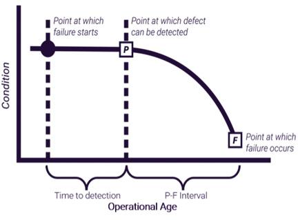
Detecting and monitoring PD is essential in preventing equipment failures, which can result in power outages, the fines that can come with these and the cost of equipment repair and replacement. However, this can be challenging, often due to the variability of the P-F curve of the assets. This represents the progression from the potential failure point (P), at which point the defect can be detected, to the functional failure point
1 https://eatechnology.com/services/conditionassessment/switchgear-condition-assessment/ partial-discharge-surveys/
(F), when the asset fails. The gap between these points, the P-F interval, is the period when operators can act to address the issue and prevent a potentially serious and financially costly equipment failure.
Periodic testing is the conventional approach but setting the optimum test interval can be a challenge due to the variability of defects and economic and logistical considerations. There is a range of factors that can impact the P-F curve including the type of PD, the type of asset and insulation, the discharge amplitude, environmental conditions and the position of the discharge.
At EA Technology we have seen many cases where the P-F curve spans just a few months. With a two-month P-F interval there is only a one in six chance that the fault with be detected in time with a yearly test and this is only improved to one in three if testing occurs every six months.
For assets that require closer attention, an alternative approach is permanent monitoring using a fixed monitoring solution, such as EA Technology’s Astute HV Monitoring®. Typically, PD sensors are attached to the outside of switchgear and around cable earth connections and this can normally be done without the need for an outage. This allows swift detection of PD issues and effective monitoring of the assets for advanced warning of potential failures. This enables shutdowns to be scheduled to inspect and repair the problem if needed with minimal interruption to customers.
Permanent monitoring can also be a costeffective approach as the annual cost of the monitoring can be saved several times over by preventing one serious failure.
An example of how permanent monitoring has worked in practice is an EA Technology customer that implemented fixed monitoring to mitigate the risk of an aged 11kV switchboard. Within 18 months, an emerging failure was detected on a voltage transformer, with data showing a rise in PD activity from zero to a high level in a matter of minutes. An outage was scheduled to inspect the transformer. Significant damage was found, indicating that the component was approaching its functional failure point. Based on this assessment, the P-F interval was estimated to be just two months. Thanks to the timely intervention, customers experienced no disruption or interruption to supply and no other components on the switchboard were affected.
Effective PD testing is essential to protect the lifespan of high-voltage electrical assets and ensure safety and reliability. Determining the optimum testing regime can be challenging due to a range of variables relating to both the equipment and type of PD. Therefore, engaging with a leading supplier of testing and monitoring solutions can help ensure the correct option is chosen for each application to ensure long-term peace of mind.
EA Technology has a wide range of both fixed and handheld solutions for PD testing such as the Astute HV Monitoring and UltraTEV® Plus², as well as an extensive range of services to help improve the safety and performance of electrical assets.
To find out more visit https://eatechnology.com/


