“ My passion and great enjoyment for architecture, and the reason the older I get the more I enjoy it, is because I believe we – Architects – can affect the quality of life of the people.”
Richard Rogers


“ My passion and great enjoyment for architecture, and the reason the older I get the more I enjoy it, is because I believe we – Architects – can affect the quality of life of the people.”
Richard Rogers
6.
1. Mumbai metro line 3 2. Pune Elevated metro 3. Chennaielevatedmetro ChennaiAirport Other Projects Sketches Entry Structure View
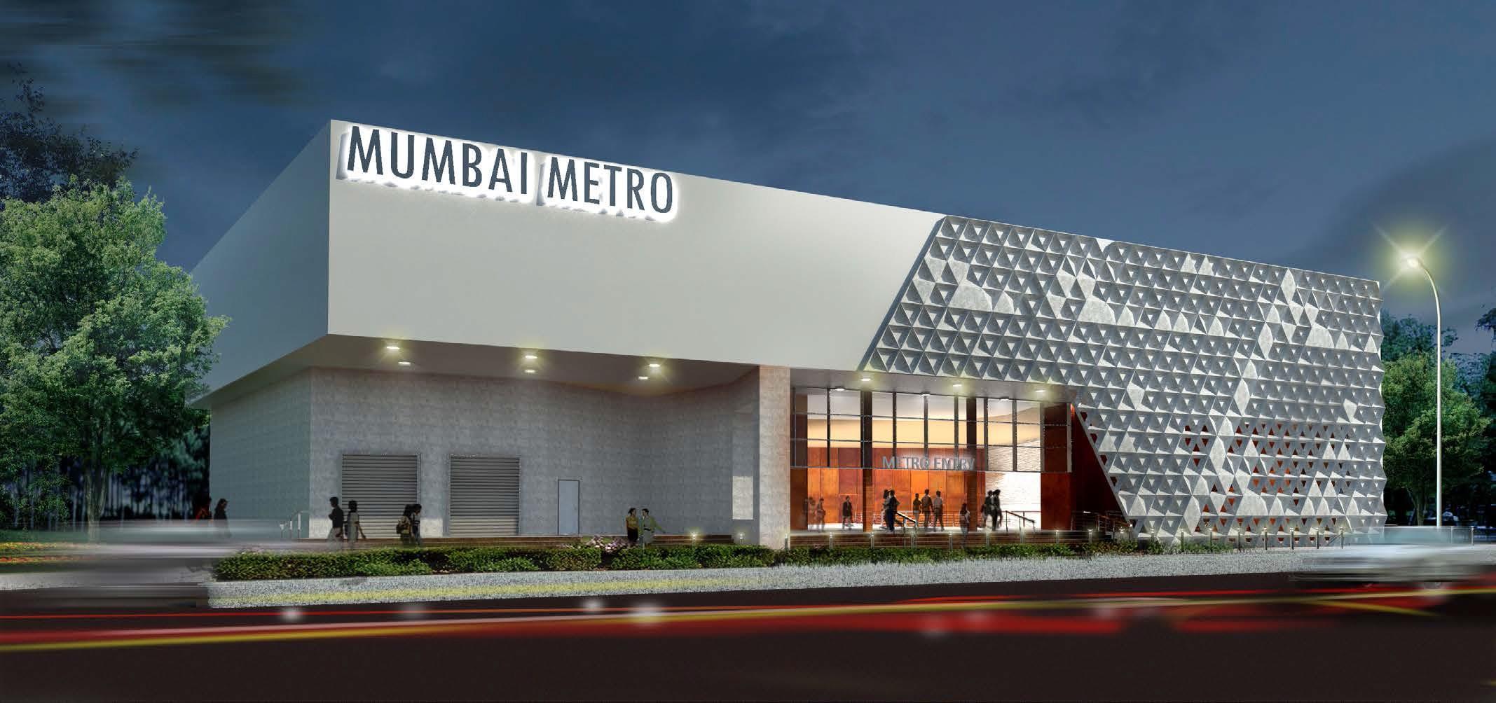
Sahar Road Metro Station
Client: Mumbai Metro Rail Corporation Ltd – GOI (50%) & GoMH (50%)
Operational: 11.4 km
Under Construction: 68.6 km
Approved: 93.79 km
Mumbai metro line 3 The Mumbai Metro system is an urban Mass Rapid Transit System (MRTS) serving Maharashtra’s capital. Its development has been entrusted to the Mumbai Metropolitan Region DevelopmentAuthority (MMRDA), who in 2004 came out with a 146.5 km master plan with multiple lines.
Due to various issues which range from policy paralysis to environmental issues, the MMRDAhas so far only been able to implement 1 metro line to connect Versova in the western suburbs with Ghatkopar in the eastern suburbs. In 2015, a new 118 km master plan was approved and the new government has provided much needed impetus for the development of 2 lines (Dahisar E –Andheri E & Dahisar – D.N. Nagar) in addition to the upcoming Colaba-SEEPZ line.
Role and Responsibility
I was hired by M/S FP design as a freelance consultant for mumbai underground metro line 3, package 6 where .the initial planning of station was done by the FP design.

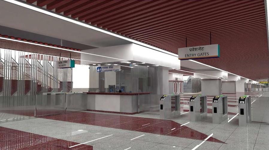
My scope was to design all the above ground structure including interior spaces of station box I have studied the layout and proposed few correction as per my design concept, in this process, I finalized material finishes related to floor finish, interior elevations and ceiling design followed by 3D Visualisations.
The concept was to design the station such that it would help in reducing the construction cost with minimalistic approch In this approach above ground structure has been composed in two different masses incorporating beautiful facade structure which helps the design look visually balanced.
At present, this design has been presented to Mumbai metro rail corporation who have agreed to incorporate it on to mumbai package-4 and on the other upcoming metro line as well.
Entry Structure - interior view


Entry Level
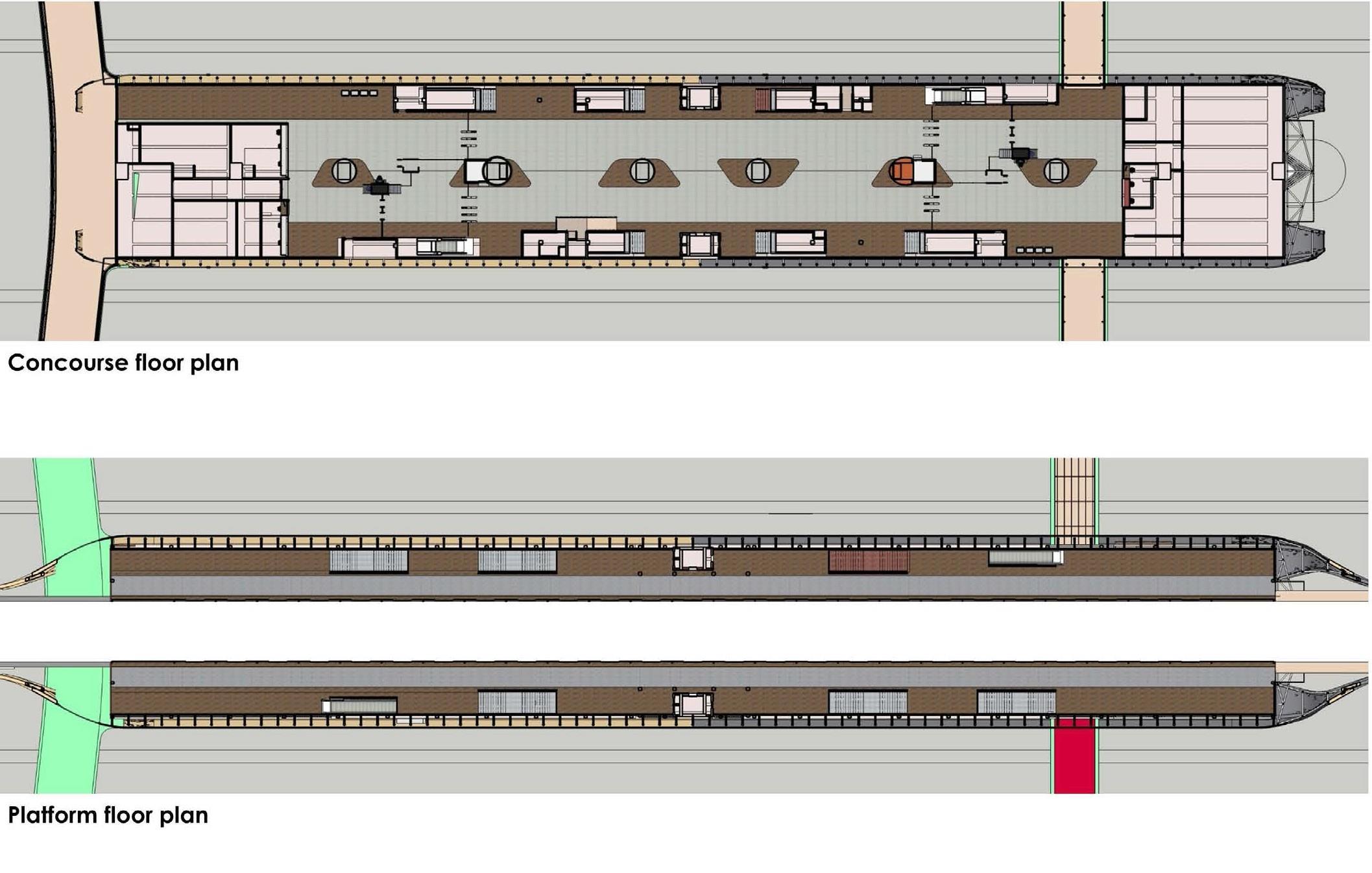
Concourse level
Platform level


 Concourse- Lift to Platform View
Concourse- UnpaidArea
Concourse- Station Control Room View
Station Interior Views
Platform- End

Pune Metro project has been undertaken by MAHA Metro, a SPV (Special Purpose Vehicle) of Government of India and Government of Maharashtra. The project intends to develop world class metro stations and surrounding areas featuring the rich cultural heritage. Modern, Safe, Secured, Comfortable and an integrated public transport system for the city of Pune and Pimpri Chinchwad will enhance the lifestyle of the citizens.

Role and Responsibility
I have worked in AYESA in capacity of anArchitect under the guidance of Chief Architect DamianAyala Lopez and MonikaAgrawal (H.O.D AYESA), AYESA is a Spanish architectural MNC specialized in infrastructure development. My role was of the team lead for Pune metro project which included 9 elevated metro stations PCMC to Range hill. I lead the team of three junior architects and five draughtsman. My responsibility was to be the face of AYESA in client meetings, Site visits and coordination with important contractors, General consultant, Structural and MEP team.
I worked on this project from scratch and done all the technical, fire egress calculation to construction drawing level. This project was very challenging in terms of site constraints, where the land acquisition is big issue for entry structures. As Pune is one of the big metro cities of India so we considered the prime status for station design. We proposed two design options for the project; one of which was conceptualized in organic form and other was in industrial form. The idea was to design the station such a way that it enhances the identity of the city. Although the facade is the soul of project but this project lacked in technological solutions.
Currently the station viaduct has been constructed and foundation of entry/exit level has started.
 Industrial station design


 VM Zinc Flatlock clading

The ceiling light is complimented with granite flooring band running parallel to it.
Shape of column is replicated in the floor as a highlighter
Concourse Interiors
Combining the organic pattern with the orthogonal from of columns to derive the pattern of ceiling and flooring Light strip Column External FacadeConcourse level plan
Platform level plan

Design option 01


Design option 02
Design option 03
Platform view


The façade of every station Will be customized by the definition of a particular façade panneling configuration, and by the definition of custumized graphics applied to the perforated metal panels.


The modular configuration of the station façade defines the relationship with the urban environment as well as the sun control and natural lighting at concourse and platform level

It defines the support for local station customization
 Portal Structure “ I ” Section
Portal Beam
Structural Beam
Corten Steel cladding Floor Finish
Perforated metal Panel
Facad e
Portal Structure
“ I ” Section
Portal Beam
Perforated metal Panel

Column
Lift to Concourse
Platform Level


Location : Chennai Airport, Chennai
Client : Chennai Metro Rail Limited & AAI
Cost : 60 Crores ($12 millions)
Area : 18,000 sq.m.
A Metro Station is designed right at the centre of the Airport City-side thus providing a fast and convenient connectivity with both domestic and international terminals making it an integral part of the multi-modal Interchange Transportation Hub at chennai airport.
The building had to be subtle yet dynamic in form justifying its central location of the site yet not overpower the Airport Terminal The building thus designed is with portal frame inspired from the now famous V-columns of the Airport adheres to the language of the whole campus and also gives a unique identity of its own.
The metro station has a total area of 17, 300 sq m with five levels:

•Basement: Car parking facility for airport users
• Ground level: Car parking facility for metro rail users
•Metro station ground level: Offices of metro rail and space for passengers
•Concourse level: Ticket counters and other facilities. Passengers will be able to access airport terminals through an access link tube from this floor
• Platform level: Metro trains will arrive on this floor
Role and Responsibility
Chennai elevated metro - Roof structure
I joined Creative Group right after my graduation in May, 2012 as anArchitect. The firm is situated in New Delhi, India and mainly specializes in Airports and Metro station designs. Here I worked with Senior Architect Rahul Dixit; under his guidance I got exposed to mega projects like ChennaiAirport, Vadodara Airport, GoaAirport and Chennai Metro station where I was mainly responsible for ChennaiAirport link metro station and ChennaiAirport.
Chennai Metro station is connecting station to ChennaiAirport and one of the important means of connectivity Here I had done concept design, 3D visualization and prepared General Arrangement Drawing and Good for Construction Drawings for the project, coordinated with all respective consultant. I was also involved into bid Documentation and learnt the process of bidding for new projects


 Portal Construction- CMRL
 Station view -CMRL
Client: Airports Authority of India
Cost: 2015 Crores for Cityside andAirside Development.
Area Awarded cost of City side 1,212 Cr
Domestic Terminal: Total Built up area more than 2,00,000 sq.m.

Intl. Terminal: 67,700 sq.m.
Multilevel Car Park: 59,300 sq.m. Electrical
Substation: 37,500 sq.m. Passenger
Capacity: 9,738 sq.m. Domestic Terminal10 million pax / year International Terminal - 4 million pax / year
Chennai international Airport Situated in India’s Tamil Nadu region, Chennai Airport is a gateway to the southern part of the country,The terminal buildings are elegant modern structures defined by dramatic, twin winglike hovering roofs providing 300-meter-long, column free space. The straight forward plan- ning and super-efficient organization of the program, security and circulation form the basis of an innovative design that incorporates vibrant sustainable gardens. Unlike any other airport in the world, lush green gardens are visible throughout the terminal creating a unique dialogue between engineering and nature, interior and exterior spaces and man’s relationship to earth and air travel. Design of the Terminal is day-lit with a carefully crafted narrow floor-plat thus minimizing the reliance on artificial light.
This project was done in a consortium of Creative group, Gensler and Fredric Schwartz Architect. Here again I worked with Senior Architect Rahul Dixit. The project was into construction stage when I was involved in this project and the main responsibility was given to prepare General Arrangement Drawing and Good for Construction Drawings for the project, coordinated with all respective consultant. I learnt the art of coordination between various services drawings through this project. This was a great learning ex- perience in view of a beginner in the professional career. Later when the project was completed, I was responsible for as built drawings, checking the actual quantification to support the billing team.


The Kalzip 65/400 aluminium roofing system designed, and installed to withstand the expansion and contraction forces resulting from an atmospheric temperature range 5 to 45 degrees Celsius. The complete roofing system meets the required thermal (U) performance of maximum 0.16 W/m2K.
Domestic Terminal Section through multilevel car parking

Bricks have been replaced with AAC blocks (aerated autoclaved concrete blocks), which ensures better thermal insulation as thermal conductivity of aac blocks is 0.16 kwm/c as compared to bricks having thermal conductivity as 0.81 kw-m/c. thus, AAC blocks offer 50% more insulation as compared to conventinal bricks.
Shade to external walls from strong sun by the 30m high trussed roof. roof insulated by the use of kalzip aluminum roofing system having u value of 0.16 w/m2k asc ompared to normal roofing having u value as 0.26 w/m2k offering 25% reduction in hvac load.
High performance double skin glass with solar factor 0.25 has been used,which gives approx. 50% reduction in heat as compared normal double skin glass having solar factor as .4 ensuring less heat gain and maximum light penetration,thus also reducing the load on air conditioning.
Unlike any other airport in the world, lush vertical gardens are visible throughout the terminals creating a unique alliance between engineering & nature. Gardens comprise of stainless steel structure lattice providing support for hanging plantings with vibrantly colored lush vegetation including orchids.


Innovative v- column was adopted to accommodate the glass connecting tube
24Nos travellators of 1000mm width are provided for movement of passengers from one terminal to another


Connector tube supported between V columns at grid of 14 m
 Ms tubes at 2800mm c/c
Length of tube – 700 m long, Width – 6.5 M
Interior picture of connector tube
connector tube


400mm thick steam cured hollow box beams are laid to create waffle thin flyover to achieve sufficient clear height in the glass tube running below the flyover.
 Elevated Corridor : V-Column erection
The steel columns supporting the glazing are made independent of main roof structure & the same was erected only after dead load is experienced by the roof structure.


 Truss supporting double height roof
The roof consists of tubular space frame of approximately 48 m span with 24m cantilever at city side. The space frame is supported on R.C.C column on one side and other side on tubular tapered V column pinned at both top & bottom.


 Abu Dhabi National Oil Corporation(ADNOC Distrbution Agartala Airport
IIT Kanpur Research Centre
MLCP GIFT, Ahemdabad, Gujrat

