PORTFOLIO

ABHINAY KUMAR / ACADEMIC
B.Arch / M.Engg


ABHINAY KUMAR / ACADEMIC
B.Arch / M.Engg
B.Arch / M.Engg
completed my Master's in Façade Engineering in july 2022, Prior to my Master's program, had over 7 years of experience as an architect, working on various projects including airport design, metro station construction, and both residential and commercial buildings. In my previous roles, was responsible for designing and assisting in the oversight of projects from conception to completion. submitted my thesis on “evaporative cooling facades for hot and humid climates -focusing on reducing carbon footprint and energy seving” in July 2022 and am now seeking employment opportunities in facade engineering firms.
Masters in Integrated Design (Facade Eng.) - March 2019 to August 2022
Technische Hochschule Ostwestfalen-Lippe, Detmold, Germany
Facade Engineering Masters - Grade:- 1.5
Bachelor of Architecture - July 2007 to 2012 May
National Institute of Technology Raipur, C.G., India
National Institute of Technology Raipur C.G., India
Skills
Athena
Comsol (Thermal)
Flixo
Therm
Autodesk Flow
2D Energy
Frilo Strurcture (for Wind calculation)
Portfolio Link
Schucal
Auto CAD
Revit
Google Sketchup
Archicad
Rhino
Grasshopper
Python (basics)
Intern, Facade design, 2021 Aug to 2022 Aug (1 Year)
Absolute design workshop co. Ltd Cambodia (Facade design Firm) completed an internship during my master’s program where my responsibilities are
1. Making Detail Brief Reports for facade
2. Energy simulation (daylighting, thermal, U value calculation, basic load calculations for profiles )
3. Developing Initial cad Detail drawings, Shop drawing preparation
4. Material proposal and selection.
Architect, 2018 Aug to 2019 Aug (1 Year)
Ascons india Pvt. ltd. Surat (Architecture - Interior Firm)
Projects: Apartment, office, Residential architectural, and interior work
1. Architectural drafting and detailing
Project Architect, March 2016 to August 2018 (2 Year)
AYESA India PVT ltd Hauz Khas, Delhi-Noida
Project: Pune metro Rail (9 elevated metro station)
Vijayawada Metro Rail (24 Elevated Metro Stations), Corridor 1 –(11stations), Corridor 2 -(13 stations),
1. Team manager and station Designer, Responsible for overseeing a team of eight individuals,
2. Reporting to the senior architect. Responsible for client interaction, systematic documentation, and timeline decisions to expedite the work’s completion,

3. Review of tender drawings and documents, creation of conceptual drawings, station reports, evacuation calculations, and construction specifications, Client presentation preparation Coordination with internal Services and Structural departments, as well as final verification and adjustment of the drawing.
Junior consultant, Nov 2013 to March 2016 (2.5 Year)
Pell Frischmann Prabhu, Gurgaon,
Projects: Chennai central metro along with more than five metro stations. (Underground metros), Mumbai metro pre-bid Competitions.
1. Design Signages for all underground metros,
Ladybug
Honeybee
Karamba
Adobe Photoshop
Adobe IN-Design
Abode Premier
Lumion 3d , V-Ray. MS office.
- Academic and Professional
Abhinay Kumar Pinneichenstraße 8, 32756 Detmold
Email: architect.abhinay@gmail. com
PH No. +491789209998
https://issuu.com/abhinaysharma/docs/facade_portfolio_abhinay_2023
1. Best graduate in masters in facade- achivement award at university TH-OWL 2022
2. First position in National Interior design Competition (Commercial Complex) 2010,
3. First position in (Global Art and Craft center) BIRLA WHITE YUVA RATNA AWARDS 2011
4. First position in a landscape design competition, Zonasa ’08.
2. Assisting senior consultant and preparing client interface presentations.
3. Preparing Construction reference Drawings, Definitive design drawings with internal teams,
4. Involved in Coordination with MEP, and HVAC consultants..5
Architect Jun, 2012 to Nov 2013 (1.5 Year)
Creative Group, Delhi
Projects; - Chennai Airport, Chennai metro (Elevated metro) Airport Link, Ananda housing, Chennai. As a fresher architect, my role was to
1. Assist senior architects,
2. Review of As-Built drawing, Shop drawing,
3. Managing Site co-ordination,
4. Making GFC drawing and presentations.
5. Planning residential building layout, using cad and 3d software.
Architectural Intern (6 Months)
M/S Prabhakar Bhagwat landscape Architects, Ahmadabad (2011 June) 6-month Professional training under the experienced guidance of Prof. & Ar. Aniket Bhagwat (CEPT Univ.)
Projects: - Maha Eco 6000-acre phase-1, Calcutta Riverside master plan
1. Drafting site layout, Plan sections and elevations.
2. Detailing of road layout with contour calculations using AutoCAD, and SketchUp,
3. 3d model making
(2 year)
01/01/2021 – current
Online Work (2022 to current)
Intern (2021 to 2022- 1 year )
Absolute design workshop co. Ltd
Cambodia
(3 years)
March 2019 to August 2022
Masters in Integrated Design (Facade Eng.)
Technische Hochschule Ostwestfalen-Lippe, Detmold, Germany
P9- Snapping facade (Parametric facade)
(1 year)
2018 Aug to 2019 Aug
Architect,
Ascons india Pvt. ltd. Surat.
Architecture and Interior designing firm
P5- KA 100 harbor - Algae facade Tower
P4- Schuco, Herford Germany (stick system)
(2 years)
March 2016 to August 2018
Architect, AYESA India PVT ltd
Hauz Khas, Delhi-Noida
S5- Facade for an Office building in Cold climate- unitized facade
construction
(2.5 years)
Nov 2013 to March 2016
Junior consultant, Pell Frischmann Prabhu, Gurgaon,
S6-CityPride - London (unitized facade - Modified)
(1.5 years)
Jun, 2012 to Nov 2013
Architect, Creative Group, Delhi
(5 years )
July 2007 to 2012 May
Bachelor of Architecture
National Institute of Technology
Raipur, C.G., India
TH-Thesis- Eva-Co-Facade
Evaporative cooling system integration to facade for hot and humid climate in india

Location - New Delhi, the wet season is hot, oppressive, and partly cloudy and the dry season is warm and mostly clear.

Snapping Concept - Actuate each grid panel responsively to the environment and users, through minimal snapping motion, keeping the system simple but efficient.
Configurations - Each module is composed by a pair of metalic blades, active bendeded to snap (change direction) with just a trigger actuator (stepper motor). Both blades are connected with the membrane, that twisted can have four different configurations to maximize views and block solar radiation according to the ambient and user necessities .

Integrated Frame
Open setting- Weaving membrane in its open state Closed setting- Weaving membrane in its closed state (outter blade snapped)
Skewed setting - Responsive snapping facade module placed in a skewed rectangular grid - With the sensors, stepper motors and supporting rods


Each facade panel has the capability of being configured into 4 different settings. Through a triangulation of light/ heat sensors and motion sensors on each integrated frame, the stepper motors are activated to set the shading in the best possible configuration.
The internal heating gain could then be optimized to up 700/o of inner radiation on floor reduction. While closening and filtering the sun lights, the membranes still process the air. Its unique configuration, allows as well to keep internal views not only with the configuration options but as well with the translucency of the material.


For this snapping facade, we are using knitted nylon and polyphenylene sulfide fabric embedded with hydrogel and terracotta seeds where hydrogel has the capacity to store water of 300 times of its weight, and terracotta having the property of evaporative cooling. hydrogel helps terracotta to wet, After heating, via sun it helps to cool air throughout the day in summer. The perforated fabric allows air to pass through the composite material and cool the air which is balancing the indoor temperature.


UDC 80 Schuco system has used and modified to fixing the stepper motor to the transom and mullion. operable facade window allowed to ventilate the indoor climatic environment.

whole facade module hang to the slab with the support of slab brackets which gives the opportunity to align facade to maintain tolerance in both directions. additional brackets has been introduced in top and in the bottom of slab to the stepper motor bar to provide strength to fabric structure.
 Elevation
Plan
Section
Facade Detail
Facade instalation Detail
Unitized ‘optimized’ snapping Facade (UDC 80)
Note:- The proposed screw connection in the conceptual facade design needs to be reinforced for enhanced strength to securely hold the facade panels in place. Considering the Schuco detail, modifications have been made to ensure the practical realization of the facade panel. These modifications aim to optimize the connection’s robustness, ensuring reliable attachment and stability of the facade panels

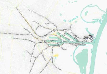
The project develop itself in the year of 2050 when the Karlsruher coal power plant, at the border of the Rhein river, will be shut down. To solve the increase gap of new housing places, specially in contact with nature, KA 100 Harbor plans to be a mixed used development by creating a cohesive park-higlines network from the Rhein river to the city center of Karlsruhe.
Neither the natural world nor the man-made world is entirely satisfactory since people are a part of nature as a biotic component and all communities, whether strongly influenced by humans or not are also part of nature. However, because of humanity pervasive influence , no area is completely isolate from its direct or indirect effects.
KA 100 Harbor is an approach to create relationship between man made and natural ecosystem . it will balance the built systems designed life while incorporating nature, recycling the demolish waste material, using renewable methods derivate from coal related activities to regenerate built environment. It will reduce the ecological consequence which influences the ecosystem , there structure and its functioning.


The higlines, composed by a series of green ramps will house housing/ commercial units, while creating across the network green spaces for people to have once more contact with nature and with the river, since the city didnt developed itself across it. A main feature of it will be the integration of new kinds of transports like the hyperloop and reversed tram.


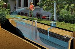
By dissolving and integrating this highlines network through the already built environment of the city, like railways, roads and clusters, the project aims to offer more recreational and cultural spaces to the community with the slopes generated.

Regarding its structure, the higlines are composed by Ashcrete and Biochar, both from coal derivatives which usually would be thrown away. The higlines themselves aim to filter rain water and distribute it along the city through the higlines, while the main building will be upcycled to tower units with algae energy generating facade systems.
Residential POD on highline

Conceptual Facade system has designed for futuristic POD to ventilate the indoor climatic environment.


whole POD module has been made of biochar and hydroplastic panel to maximaise sustanablity. where biochar offers excellent thermal properties, including high thermal mass and insulation capacity, which can regulate the temperature inside the POD and reduce the need for mechanical heating or cooling systems. Additionally, biochar’s adsorption properties enable it to capture and retain pollutants, contributing to improved indoor air quality. Furthermore, biochar is a renewable and sustainable material derived from organic waste, aligning with the principles of the circular economy and reducing reliance on non-renewable resources. By integrating biochar into the facade system, the POD achieves enhanced thermal regulation, air purification, and sustainability. Hydroplastic panels are a type of lightweight and flexible material that can be molded or shaped. They are designed to be water-resistant, durable, and have excellent insulating properties.


 Hydro plastic panel Wooden ceiling Wooden Flooring Facade Frame
3D printed Ashcrete


 Cyclic procedure of algae facade-energy generations
Karlsruher coal power plant-algae facade Tower
Algie Facade system
Futuristic Residential POD View- Roof algie Panel


Algei facade panel detail


For the first semester of the Master’s program in Integrated Architectural Design, students are required to complete an independent project focused on designing a new façade for the Office building located in Schuco Herford, Germany. The building is in need of a façade refurbishment due to issues with overheating during the summer. The project will involve selecting appropriate façade materials and determining the necessary calculations for elements such as glass thickness, weight, mullions, and transoms using a stick system.
By analyzing the sun’s movement over the course of a year, it has been determined that the south-west facade of the building receives the most intense sunlight, particularly during the summer. In contrast, the north facade does not receive much sunlight throughout the year. To address the issue of overheating, the solution is to reduce the number of openings on the south facade by incorporating a combination of clear glass, shadow boxes, and alucobond panels, while increasing the number of openings on the north facade.


Shadow analysis is conducted for a specific month of the year to determine the amount of sunlight that falls on different parts of the building. During this analysis, it was found that the south and west facades of the building receive the most daylight during the day. When comparing the months of March and June to September and December, it was determined that the latter months have a higher level of sunlight exposure, particularly during office working hours. This means that the building will experience the maximum amount of solar radiation during these months.
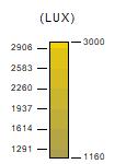


The following illustration shows all the floor plans of the building. An analysis was carried out for the month of September, under clear sky conditions during daytime. The results of the analysis show that the east and south facades of the building experience the highest level of solar radiation, reaching 3000 lux for typical floors. In order to provide a comfortable working environment in an office building, it is necessary to maintain a level of light intensity between 300 to 1500 lux . To achieve this, external louvers or tinted glass can be used on the facade to reduce sunlight intensity and prevent glare.


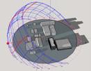


System components
The project will use Schuco FWS 50’s Ladder facade construction, which involves an aluminum or steel ladder-like frame structure for cost-effective and efficient construction of large glass facades. The design has minimal visible framing and good sound insulation, with overlapping gaskets ensuring high watertightness. The minimal face width of 50mm and glass thicknesses of 5/6mm for single glazing and 22-24mm for insulating glass provide excellent performance. The ladder construction with spring bolt T-cleat saves time during installation.
Sheet metal blades; open design (single-skin)


The single-sheet metal blade offers transparency and solar shading tn ono.The top sheet is individually perforated. The louvre blade widths of 470mm, 580mm, and 690mm “can be used as standards.”
Main idea of usind perforated louvers as a second skin of the facade to prevent solar to the oficce space

To determine the appropriate size for the mullions, transoms, and glass panels, it is important to analyze the facade loads by dividing the overall facade into different cases based on panel size, mullion length and width, and transom variations. This approach allows for a more thorough examination of the loads and stresses on the facade, and can aid in identifying potential areas of vulnerability or hazard. Additionally, by considering factors such as wind loads, thermal expansion and contraction during the analysis, it can help ensure that the facade is capable of withstand different environmental conditions. This approach enables to optimize the size of the mullions, transoms and glass panels as per the calculated loads.

WIND LOAD ACTIONS - CASE-01
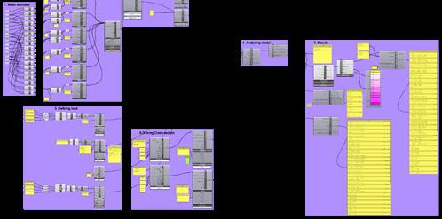

Moment of inertia due to (suction wind force) on mullion Uneqal double span curtain wall
In this experiment, the deflection and support reactions of a facade panel were analyzed under a mesh load of 1.12 kN.m2, equivalent to wind suction force. The process began with the development of the panel geometry, which was created using a plane in Grasshopper and converted into beams and a mesh load using the Deconstruct Brep tool. The resulting geometry was used to define the panel elements, supports, and mesh load, which were then analyzed to determine the deflection and support reactions of the panel under wind load

WIND LOAD ACTIONS - CASE-02 & CASE-03
Moment of inertia due to (suction wind force) on mullion Eqal Single span curtain wall
WIND LOAD ACTIONS - CASE-01 (Transom)
Moment of inertia due to (suction wind force) on Transom
Load due to Glass
For karamba calculation I have selected the biggest mullion length ie 4.3 m which has calculated as in manullly in above slides where wind load taken p= !.12 kn/m (suction ) on east facade due to wind load on south facde.
DEAD LOAD ACTIONS - CASE-02 (Transom 2)
profile
The weight of the panel calculeted from the U-Wert online softwere, Where panle weight has calculeted is 21.5 kg/m2.
Length of panel =1.10m, Height of the panel = 1.38m
Weight of the panel= 21.5 x 1.10 x1.38 = 32 kg
All statements without guarantee
Exterior wall created on 28.3.2020
U = 0,26 W/(m²K)
Bestand*:
W/(m²K) excellent insufficient Moisture proofing No condensate
excellent
shift: 5,8 h
Thermal capacity inside: 10,8 kJ/m²K
Temperature and dew-point temperature in the component. The dew-point indicates the temperature, at which water vapour condensates. As long as the temperature of the component is everywhere above the dew-point temperature, no condensation occurs. If the curves have contact, condensation occurs at the corresponding position.
Aluminum foil
# Material λ R Temperatur [°C] Weight [W/mK] [m²K/W] min max [kg/m²] Thermal contact resistance* 0,130 18,8 20,0 1 0,3 cm Aluminum foil (coated) 160,000 0,000 18,8 18,8 8,1 2 15 cm Extruded polystyrene (XPS) 0,040 3,750 0,2 18,8 5,3 3 0,3 cm Aluminum foil (coated) 160,000 0,000 0,2 0,2 8,1 Thermal contact resistance* 0,040 0,0 0,2 15,6 cm Whole component 3,920 21,5
Wx
durch die Werkstoffkombination ist bei der
= 376.95 = 505.29
We have to selected mullion from schuco. which has heigher momment of inertia (with steel insert) then calculated moment of inertia for safer structural calculation
0,2°C
The maximum permitted stress adopted must be in accordance with the type of glass to be used. The result obtained from the calculation is the minimum thickness the glass must have.
=Minimum glazing thickness in mm.
=Shape coefficient according to table

=Shortest side of glass in mm.
=Longest side of glass in mm.
of appropriate transom for facade Calculated
= 3.93 x 1.7 = 6.7mm
=Designed wind load in [N/m2]
=Permitted stress in the glass [N/m2] = 5x10⁷ N/m2 (toughened glass subjected to permanentstresses)
Page
WärmeschutzVODIN410895EnEVBestandniedrigeTiEnEV14NeubauU=0,25EnEVBestandEnEV16NeubauESanMVU=0,2 KfWEinzelmaßn. NeubauKfW55EWärmeGBW 3-Liter-HausU=0,15 NeubauKfW40 PassivhausU=0,1
As we have taken 14 mm thick glass (6 +4+4 ) which is greater then required glazing as per calculation.
Thickness:
Bei
der Serie
all mullion profiles with 3 mm wall thickness, use suitable button T-cleats from the FWS 60 series. To


I conducted an analysis to determine the impact of using polyarnid as a thermal barrier and polyurethan as an insulator on the U-value calculation for frames and joints. The calculation was performed in accordance with the European standard EN 150 10077-2, which specifies that the glass must be replaced with a panel with a X=0,035 W/mk and the visible portion of the panel must be at least 190 mm


Figure on the left side show the Ψ value for combination of mullion and window frame with glass on both sides. Meanwhile, the fi gures at right side below shows how the isothermal in the construction.
However the fi gure shows that the lowest inner surface temperature is slightly under 10 °C (need to be aware of it, as condensation can happen here) in the connection of window frame and glass. More insulation material need to be added inside the window frame, or a change of the frame.
Interior Climate : +20 °C, 50% rel. humidity
Exterior Climate : -10 °C, 80% rel. humidity
 Schuco Herford , Germany
also a rich in architecture history and famous for its modern and contemporary style.
of the project is inspired by Danish word Solar Kontor means passive offices space
Cloud Cover Categories
ABOU T
Oslo has challenges to Reduce CO2 emission by 2030, Keep global warming below 1.5 degrees Celsius to Improve the Air Quality Control over noise pollution and also Using the sustainable approach in construction method to reduce energy consumption.
Daily Chance of Precipitation
main task was to design a façade for an office building in Oslo in Norway. Which has required to consider the climatic condition of colder region, for example Oslo has longer day hour approx. 17 hour in a summer season and having direct sunlight issues. Which has inspire me to incorporate the passive heating aspects to the façade which helps to reduce energy consumption and also increase the comfort in indoor space
Humidity Comfort Levels
Average High and Low Temperature
In Oslo, the summers are comfortable and partly cloudy and the winters are long, freezing, and mostly cloudy. Over the course of the year, the temperature typically varies from 19°F to 71°F and is rarely below 1°F or above 80°F.
Tourism Score
word Solar Kontor means passive offices space.
In Oslo, the summers are comfortable and partly cloudy and the winters are long, freezing, and mostly cloudy. Over the course of the year, the temperature typically varies from 19°F to 71°F and is rarely below 1°F or above 80°F.
Cloud Cover Categories
a multi -ethnic city and its culture can be described as urban. Oslo is famous for its Museums and art heritage. Oslo has rich in architecture history and famous for its modern and contemporary style. has challenges to Reduce CO2 emission by 2030, Keep global warming below 1.5 degrees Celsius to Improve the Air Control over noise pollution and also Using the sustainable approach in construction method to reduce energy consumption.
Daily Chance of Precipitation
Humidity Comfort Levels
for an office building in Oslo in Norway. Which has required to consider the climatic Oslo has longer day hour approx. 17 hour in a summer season and having direct to incorporate the passive heating aspects to the façade which helps to reduce the comfort in indoor space.


Average High and Low Temperature
can be described as urban. Oslo is famous for its Museums and art heritage. Oslo has famous for its modern and contemporary style.
Tourism Score
Oslo, the summers are comfortable and partly cloudy and the winters are long, freezing, and mostly cloudy. Over the of the year, the temperature typically varies from 19°F to 71°F and is rarely below 1°F or above 80
June 21 to Sep 20
emission by 2030, Keep global warming below 1.5 degrees Celsius to Improve the Air also Using the sustainable approach in construction method to reduce energy
Cloud Cover Categories
Daily Chance of Precipitation
Humidity Comfort Levels
Average High and Low Temperature
Facade for Office building in two climate zone -

and partly cloudy and the winters are long, freezing, and mostly cloudy. Over the typically varies from 19°F to 71°F and is rarely below 1°F or above 80°F.
Tourism Score
1. Hot climate,
2.Cold climate
Spring solar Summer solar
SUBMITTED BY - ABHINAY KUMAR
June 21 to
Summer solar
that
ABHINAY KUMAR
Sep21 to dec 20
Dec21 to march 20
Winter solar
The solar chimney is an ancient system used for passive heating and cooling in buildings. It involves a tall chimney coated with a material that has high thermal absorbency. During the day, the chimney absorbs heat energy from the sun, which heats up the air inside, causing it to rise and create a suction at the base of the chimney.

getting direct - perpendicular sunlight to 6000 having the maximum wind force from the envelop in terms of comforting office space.
Dec21 to march 20
Fall solar Winter solar
illustrates facing a south direction where it is getting direct - perpendicular sunlight radiation on building. The façade is having the maximum wind force from the facade correspond with these climatic issues in of comforting office
Dec21 to march 20
above solar analysis illustrates that Building is facing a south getting directsouth and having approx. 3000 to 6000 lux radiation on building having the maximum southwest direction. So the facade envelop should correspond in terms of comforting


The design of a façade for an office building in Oslo, Norway, was a challenging task. The region is known for its colder climate, with longer day hours in the summer season and direct sunlight exposure. To address these issues, I decided to integrate passive heating elements into the façade design.

20 Sep21 to dec 20
Dec21 to march 20
Fall solar Winter solar
The use of passive heating elements in the façade is a sustainable and energy-efficient solution that helps reduce energy consumption. By capturing and utilizing the heat from the sun, the building can maintain a comfortable indoor temperature, reducing the need for additional heating. This not only saves energy, but it also contributes to a more pleasant and comfortable indoor environment.
The solar analysis shows that the building faces the south direction, receiving direct, perpendicular sunlight from the south, with approximately 3000 to 6000 lux radiation on the building. The façade is exposed to the maximum wind force from the southwest direction. Thus, the façade design must address these climatic conditions in order to provide a comfortable office space.
Building is facing a south direction where it is getting direct - perpendicular sunlight 6000 lux radiation on building. The façade is having the maximum wind force from the envelop should correspond with these climatic issues in terms of comforting office space.


1. Hard insulation
2. Insert bracket (To support sliding window)
3. Sandwich panel
4. 50x80mm steel section
5. Insert profile
6. U facade bracket
7. Window frame
8. Angle section
9. Triple glazing
10. Insulation
11. False cieling
12. Water protection membrane
13. Floor finish
14. External insulation sheet
15. Wood support
16. Aluminium cladding
17. T- MS section frame
18. 50x100mm steel section
19. L-shape bracket
20. Sliding folding window

21. Chimney duct
22. Insulation over layer
23. Mortice round offset hinge
24. 50x50mm steel section
25. Glass Railing
26. Water Drainage from facade
27. Stone claddding
28. Catwalk platfoem
29. Air Inlet/Outlet
30. Pivot set
1. Hard insulation
2. Insert bracket (To support sliding window)
3. Sandwich panel
4. 50x80mm steel section
5. Insert profile
6. U facade bracket
7. Window frame
8. Angle section
9. Triple glazing
10. Insulation
11. False cieling
12. Water protection membrane
13. Floor finish
14. External insulation sheet
15. Wood support
16. Aluminium cladding
17. T- MS section frame
18. 50x100mm steel section
19. L-shape bracket
20. Sliding folding window

21. Chimney duct
22. Insulation over layer
23. Mortice round offset hinge
24. 50x50mm steel section
25. Glass Railing
26. Water Drainage from facade
27. Stone claddding
28. Catwalk platfoem
29. Air Inlet/Outlet
30. Pivot set
1. Hard insulation
2. Insert bracket (To support sliding window)

3. Sandwich panel

4. 50x80mm steel section
5. Insert profile
6. U facade bracket
7. Window frame
8. Angle section
9. Triple glazing
10. Insulation
11. False cieling
12. Water protection membrane
13. Floor finish
14. External insulation sheet

15. Wood support
16. Aluminium cladding
17. T- MS section frame
18. 50x100mm steel section
19. L-shape bracket
20. Sliding folding window


21. Chimney duct
22. Insulation over layer
23. Mortice round offset hinge
24. 50x50mm steel section
25. Glass Railing
26. Water Drainage from facade
27. Stone claddding
28. Catwalk platfoem
29. Air Inlet/Outlet
30. Pivot set


 Office building in Oslo, Norway,
London , City pride -Skyscraper
The task of designing a facade for a skyscraper in London, UK presents several challenges, such as coping with the dense population and pollution of the city, as well as high winds and traffic. Additionally, energy issues must be taken into account. Therefore, the design should strive to adapt to the local environmental conditions and provide a solution for cooling the indoor space without depending on active energy sources.


London has a mild, temperate maritime climate with cool summers and mild winters. January averages around 6°C (43°F) and July around 19°C (66°F). Rainfall is evenly distributed, with October and November being the wettest months. Occasional heatwaves, fog, and smog occur. Air pollution is a growing concern for residents and policymakers.
For the London facade design project, passive cooling strategies are necessary to reduce wind pressure and improve energy efficiency. A solar box in the building facade can help regulate indoor temperature and humidity levels using renewable energy. Green roofs or walls can also be incorporated to enhance the building’s sustainability.

After conducting a solar analysis on the glass facade of the building, it was found that it receives approximately 1 kWh/ m² of solar energy. In contrast, the framed facade structure was determined to have no solar characteristics.
Wind tunnel - Pressure on facade
Solar Analysis -Radiation on floor


The solar analysis of the building’s facade showed that the glass facade receives approximately 6000 lux of solar energy, particularly on its southern side. This information helps determine the necessary glass openings on each side of the building to achieve adequate daylight illumination.


Wind tunnel - Velocity on facade


Solar Analysis- Illumineance


Based on the wind analysis, the south and west facades are subjected to high wind pressure, resulting in deflation. This, in turn, creates a suction force on the north and east facades.

It is crucial to develop a design module that considers both solar radiation and high wind pressure on the building facade. Such a design would enable the building to receive the required sunlight and allow for the opening of windows on the upper floors despite the high wind loads.
Wind flow simulation trough module


The design of the facade module includes inclinations of 35° and 45° to ensure a smooth flow of wind and enable the opening of the facade to the outer environment. This approach aims to optimize the building’s natural ventilation system while maintaining a comfortable indoor environment.
The simulation results indicate that the facade module inclined at 30° has a smoother transition of air compared to the 45° inclined facade. The 30° inclination also creates a lower wind velocity in the adjacent facade ranging from 0 m/s to 14 m/s. However, as we move higher, the wind speed increases, necessitating a reduction in the size of the facade openings to maintain a comfortable indoor environment
Floor plan

During winter, a solar box is designed with a glazed cover on the top to capture solar radiation and an operable dark-colored blind to absorb heat. The blind is located inside the box to increase the surface area for heat transfer. Once the air inside the box is heated, it is distributed into the building through vents to regulate the internal temperature and humidity levels.
Summer
During the summer season, the vents of the solar box are opened to allow the heated air to flow out, creating an air flow through the vents from the internal environment to the outer climate. This helps in regulating the internal temperature and humidity levels. Summer
The simulation results indicate that incorporating a Solar facade box resulted in an increase in indoor temperatures from passive heating methods, with temperatures reaching between 24°C to 26°C.

1.
1. Snadwich panel
2. Transom
3. Opnable louver

4. Sandwich panel
5. Window frame
6. Glass
7. Flooring
8. Unitized frame
9. Concrete structure
10. Gypsume ceiling
11. Insulation
12. Transom
13. Outer glass
14. Transom frame
15. Outer sandwhich panel
16. Insulation
17. Corner frame
18. Outer glass
19. Exhoust vent (behind glass)
20. Exhoust duct
21. Outher frame of unitzed facade

22. Bracket for hanging panel
23. Metal frame to support panel
24. Bracket for metal frame
25. Bracket for unitized facade panel
The left side view is a sectional or exploded view of a unitized facade system that includes a double-skin solar facade. The solar facade uses the solar chimney effect to capture solar heat and warm the building in winter. The system typically consists of an outer layer of glazing, a ventilated cavity, and an inner layer of cladding. The temperature difference between the outer and inner layers of the facade creates a natural ventilation system that circulates air and captures solar heat. The sectional or exploded view would show how the different components of the facade system are connected and how they work together to create the desired effect.
 Unitized facade panel detail
Location - New Delhi, the wet season is hot, oppressive, and partly cloudy and the dry season is warm and mostly clear.
EVA-Co Concept - The dissertation ‘Eva-Co Facade is an Integration of Evaporative Cooling Strategies into Building Envelopes’ aims to highlight the advantages and disadvantages of incorporating evaporative cooling systems into facades to encourage the development of climate-friendly architectural materials for office buildings that are self-contained alternatives to traditional air conditioning systems.
However the dissertation is discussed in the context of its social and scientific importance to bring new information to fill scientific gaps in the area, but most significantly to encourage the use of environmental friendly technology driven by renewable energy in the built environment. (A+BE 2018)
Air conditioning of incoming air

Dimensions of 3D panel (2500 mm long X 1000 mm wide X 150 mm deep)


3d geometry Preparation in COMSOL Multi physics
Two, three, and four-pipe systems of cooling (Jan Cremers 2016, 203)


Prototype concept
This method is divided into two parts. The first process is sizing and conceptualizing the facade cooling panel depending on evaporative cooling study results. The second step is to obtain data from the COMSOL multi-physics program to verify the hypothesis. starting with COMSOL for concept modeling and creating a COMSOL mesh for model volume settings, identifying inlets and outlets, and finishing with applying heat transfer and boundary condition integration
Simulation setup in COMSOL Multi physics
The Heat Exchange Module in this simulation includes bidirectional heat transfer and non-isothermal flow effects. Forced convection is used to mimic both laminar and turbulent flow. Pressure work and viscous dissipation are triggered in the force convection model to impact temperature distribution. Turbulence represented using Reynolds-averaged Navier-Stokes (RANS) models such as the k-, low-Reynolds k-, algebraic y Plus, or LVEL turbulence models. When used in conjunction with the CFD Module, the realizable k-, k-, shear stress transport (SST), v2f, and Spalart-Allmaras turbulence models are accessible. Depending on the flow model, the temperature change at the fluid-solid-fluid interface is automatically handled utilizing continuity, wall functions, or automated wall treatment.

Interior Temperature of Panel in comparison to the atmospheric temperature Water has a constant temperature and gains heat via heat exchange with air. The temperature of the air gradually decreases from 34 ° C to 14 ° C.
This simulation shows that the streamline velocity of air is higher as compared to water, and that air has greater space to exchange temperature in the heat exchanger module.

The simulation has been set up to analyze the whole thermal comfort evaluation in a conference room using CFD simulation, which includes models for convective heat transfer, radiative heat transfer, and air aging the idea is to analyse required thermal comfort condition which will later fulfill by eva-co-facade system.


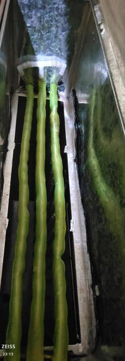




The Prototype has a dry and wet channel. The primary (supply) air flows through the outside of pipes and the secondary cool water (supply) flows through the pipes simultaneously in the opposite direction. which is often reduce dry bulb temperature of pipes up yo 1.7 to 2.2 deg C. The secondary water absorbs the sensible heat from primary air and cools down the supply air without adding humidity. The wet bulb effectiveness of evaporative cooling system is up to 40 - 80 %. the sensible heat of water is absorbed by the thermoelectric module and reduce the dry bulb temperature up to 14°C to 18 °C.
As a result, thermoelectric module produces sensible heat which again reduced by direct evaporative ceramic module, thus if evaporative system is proper insulated, it can deliverer dry air up to 19°C to 24 °C. to indoor environment without adding humidity.


therefore the the integrated facade panel runs on PV panels that allows to save energy throughout year except winters seasons. (Dr. John R.wattet al )


As the developed prototype is big in size and also complex to incorporate into the facade system, it can only have the possibility of being built with a brick wall. Therefore, the prototype can blend because of the thickness corresponding to the brick wall depth. Also, design modification is required to maximize its efficiency while minimizing the size of the panel to allow the possibility of integration with modern facade systems
The Peltier module was successfully tested on 31°C water, as seen above, and the water temperature was reduced to 14°C in 8 minutes. This cooled water is then used in an evaporative cooling panel.
The prototype was successfully tasted at an indoor ambient temperature of 31°C, as seen above, and the room temperature is decrease up to 27°C in 10 minutes duration.


 Peltier cooling module prototype
Eva co cooling panel, horizontal and vertical


PV PANEL
PV PANEL REDUCED ENERGY COST UP TO 80 % THROUGHT THE YEAR
INDOOR
Figure 39 Eva co cooling panel, Facade integration (author) Figure 41 Eva co cooling panel, Horizontal View (author)architect.abhinay@gmail.com
