HEALTHCARE FACILITIES


ENGINEERING THE CONTROLS FOR A REFURBISHED OPERATING THEATRE SUITE IN A GENERAL HOSPITAL
SO, YOU WANT TO INSTALL A HEAT PUMP?
PRACTICAL APPROACH TO ACHIEVING NET ZERO IN HEALTH CARE




29 Engineering the controls for a refurbished operating theatre suite
35 Forecasting healthcare facility
43 So, you want to install a heat pump?
49 Speedy recovery: HEPA filtration in recovery wards without upsizing fans or ductwork
55 Practical approach to achieving net zero in health care
63 Going the distance: what you need to know about breaking the 100-meter distance limitation
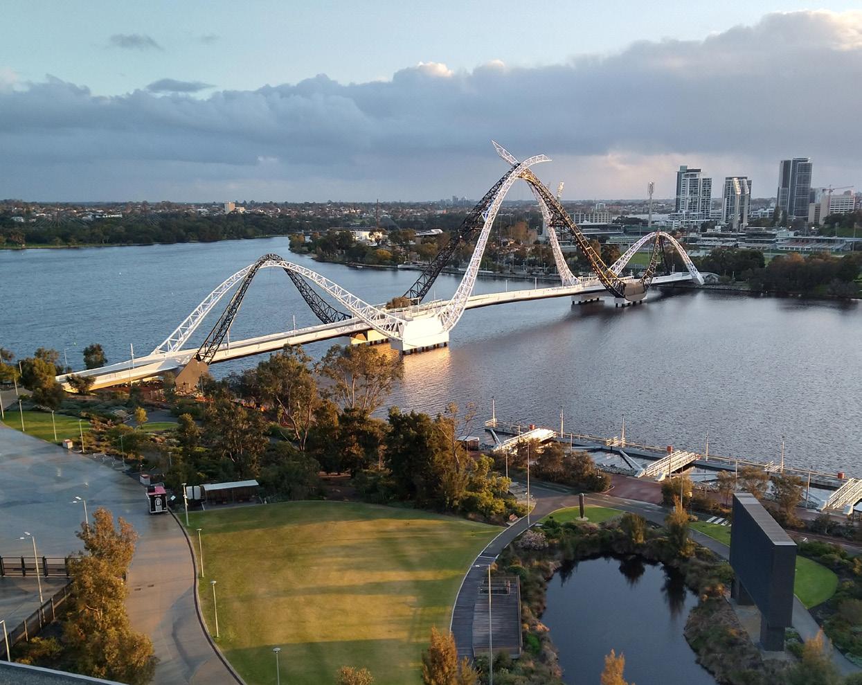
Cover: The Beautiful Swan River, Perth, WA – location for the WA branch conference details on page 19.
IHEA NATIONAL OFFICE
Direct: 1300 929 508
Email: IHEA.members@ihea.org.au
Website: www.ihea.org.au
IHEA NATIONAL BOARD
National President
Michael Scerri
National Immediate Past President
Darryl Pitcher
National Treasurer
Rohit Jethro
Communications
Darryl Pitcher
Membership Registrar
Michael Scerri
Standards Coordinator
Cameron Ivers
Visit the Institute of Healthcare Engineering online by visiting www.ihea.org.au or scanning here →
Directors
Michael McCambridge, Cameron Ivers, Fred Foley, Jana Simpson, Danny Tincknell, John Mihalinac and Jon Gowdy
IHEA ADMINISTRATION
Finance
Jeff Little
Membership
Vanessa Gallina: ihea.members@ihea.org.au
Editorial
Darryl Pitcher ihea.editor@ihea.org.au
IHEA MISSION STATEMENT To

ADBOURNE PUBLISHING
PO Box 735, Belgrave, VIC 3160 www.adbourne.com
ADVERTISING
Robert Spowart
T: 0488 390 039
E: robert@adbourne.com
PRODUCTION
Sonya Murphy
T: 0411 856 362
E: production@adbourne.com
ADMINISTRATION
Adele Spowart E: admin@adbourne.com
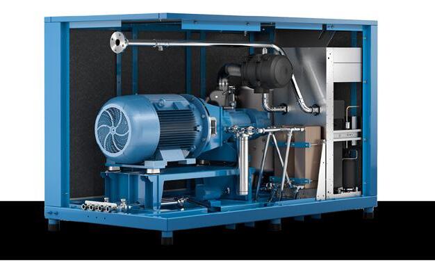

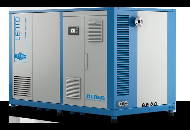

Since 1994, Cleveland Compressed Air Services have proudly provided and distributed our products and services to the healthcare industry. We have over 30 years of experience and an extensive range of high-quality products including Class ZERO Oil Free Air Compressors, Ultra Low Purge dryers, HLI enabled Breathing Air Purifiers and 15bar Surgical Tool Air Compressors. We offer tailored solutions backed by quality products, audits, installations, service & repairs.
Products Include:
• Medical Breathing Air Compressors Systems
• Medical Tool Air Compressor Systems
• CSSD Compressor Systems
• Laboratory Air and Gas Generation Systems
• Medical Suction systems
• Filtration
• On-site Nitrogen Generation Systems
• On-site Oxygen Generation Systems
Service providers for:
• Royal Perth Hospital Sir Charles Gardiner Hospital Perth Childrens Hospital
• Hollywood Private Hospital
• St John of God Hospital Network King Edward Memorial Hospital
• Fiona Stanley Hospital Joondalup Health Campus & Many more
Cleveland Compressed Air Services are authorised service representatives for well-renowned brands such as:





Our network of service technicians are available 24/7. No matter when problems arise, we’ll be there to help!
We have established ourselves as industry leaders, offering Medical Compressed Air Solutions with a wealth of experience.
We are licensed distributors of oil-free and environmentally friendly compressor solutions

The Spring edition of Healthcare Facilities celebrates the activities of the IHEA branches across the country and once again shares with you some excellent technical articles from the National Conference held in June this year.
A special thanks to all the contributors for this edition who have stepped up, whilst I have been travelling overseas. A component of the travel to Canada and USA was personal, for our daughter’s wedding in Cambridge, Ontario, and the opportunity to spend time with our US based family members in Baltimore, MD and Norfolk, VA.
During my travels I also flew from the USA to Cape Town for the 2024 IFHE International Congress hosted by the South African Federation of Healthcare Engineering and the associated meetings of the IFHE Executive Committee and Council. I was glad to be accompanied by IHEA National President, Michael Scerri, who connected with
IFHE colleagues as IHEA President and represented the Australian perspective on healthcare engineering issues at the international gathering.
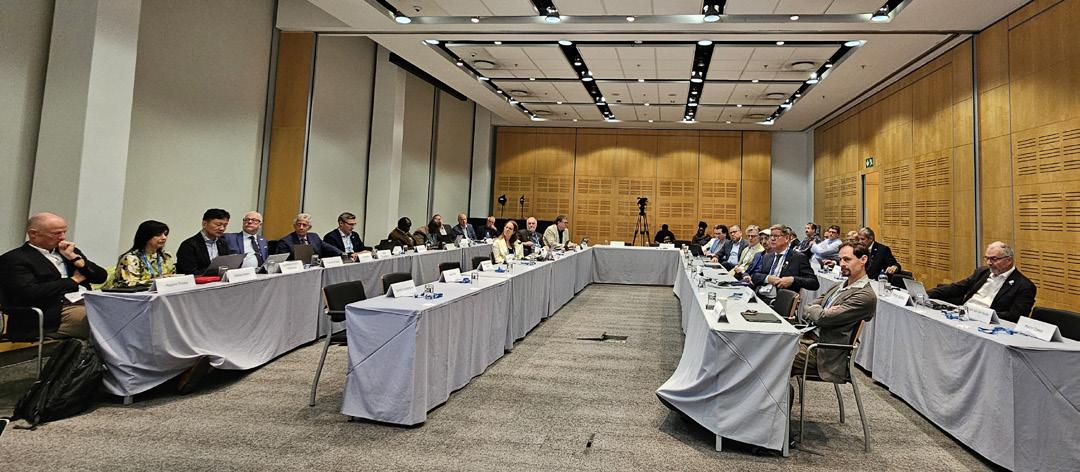
Below you will see the IFHE Council gathering, which brought together more than 20 national organisations to explore the opportunities and challenges faced by our peers across the world.
As we move through Spring, I wish all of our readers all the best and invite you to share with your colleagues this Journal and the benefits of your IHEA membership, and the associated technical and advertorial content that IHEA is happy to bring to your notice.
Regards
Darryl Pitcher – Editor
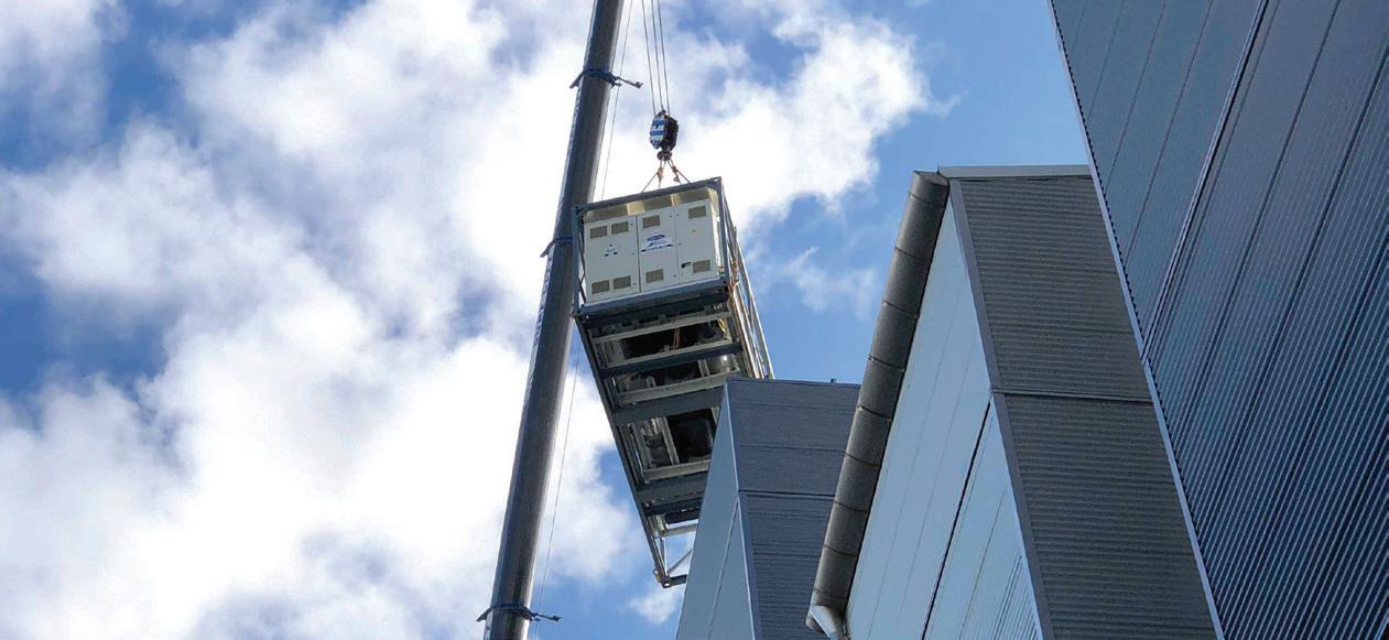

A private hospital in Brisbane was facing a delayed opening of its new operating theatres due to the late delivery of its new permanent chiller plant. This delay prevented elective surgeries from being performed, surgeries that had been booked months in advance. In addition to this, site space constraints made it difficult to place a temporary chiller, as it needed to be installed on the same concrete pad where the permanent chiller would eventually be placed. Minimising downtime during the changeover was critical. Moreover, the temporary chiller had to be located within 25 meters of residential areas, requiring careful management of noise levels.
Aircon Rentals was tasked with designing and implementing a solution that could meet the hospital’s cooling needs. With space limitations and noise considerations, the system needed to be both efficient and quiet. Aircon Rentals selected a 200kW air-cooled heat pump chiller and associated accessories to meet these requirements. The additional cooling capacity and the inclusion of a chilled water bypass ensured optimal system control. Planning for the installation, rigging, commissioning and removal required special consideration.
To address the logistical challenges of the installation, Aircon Rentals organised early morning crane truck deliveries to transport the chillers and equipment safely and efficiently. By working closely with the hospital and coordinating with the hospital’s project team, the equipment was successfully placed and secured on-site. Aircon Rentals also installed security fencing with Eco Barrier technology, which served both to secure the area and to reduce breakout noise from the chiller and pump. The installation was completed on schedule with minimal impact on the hospital’s operations.
The project’s success relied on careful coordination between Aircon Rentals and the hospital’s Engineering Team. The chiller system was tested and commissioned without issue, entering into full operational mode once installation was completed. Aircon Rentals also installed remote monitoring of the equipment. This enabled technicians the ability to control, adjust set points, start, stop, and manipulate the equipment off-site. The automated control system ensured that the chiller operated efficiently, providing the necessary cooling for the hospital’s new operating theatres.
After the hospital’s permanent chiller plant was delivered and installed, the temporary system needed to be carefully removed to avoid any disruptions to the hospital’s operations. The cooling load was gradually transferred from the rental chiller to the permanent system in stages, verifying the successful transition. Aircon Rentals worked closely with the hospital’s Engineering Department to ensure that the de-commissioning and removal processes were completed smoothly, with all activities finalised in the early hours of the morning to minimise any operational disruptions.
This project demonstrated how expert planning and collaboration with all stakeholders can ensure that essential cooling services are delivered with minimal disruption, even in challenging circumstances. Aircon Rentals provided a cost-effective, timely solution that allowed the hospital to maintain critical services, open its operating theatres on time and meet contractual obligations.
• Proposal Turnaround Time: 12 hours
• Duration: 4 weeks initially
• 1 x 200kW air-cooled heat pump chiller
• Additional capacity with a chilled water bypass for system control
• 120m of chilled water lines with piping fittings and adapters
• 160m of temporary electrical cables for the pump and chiller
• Traffic management during installation and removal
• Early morning crane truck deliveries to minimise disruption
• Security fencing with Eco Barrier for noise control
• Remote Monitoring System
• Facilit y & Hospital Engineers
• R&D Engineers
• Product Managers
• CS SD and Endoscopy Managers



In October I had the honour of representing IHEA at the 28th International Federation of Healthcare Engineering Council Meeting and Conference in Cape Town, South Africa.
Against the backdrop of a very well organised Conference hosted by the South African Federation of Healthcare Engineering, delegates received a series of high-quality, thought-leading presentations organised in three parallel streams: Sustainable Hospital Infrastructure, Human-Centered Healthcare Design, and Infection Prevention and Control.
For me, this IFHE Conference highlighted that many of the local issues we face in our healthcare facilities here in Australia are experienced consistently across every continent. For example, the supply constraints on primary healthcare and the corresponding demand pressures felt by our emergency departments (especially since 2020) are a common concern the world over. Unfortunately, a common solution is yet to be identified by governments but hopefully international congresses like that facilitated by IFHE will help us all get closer to solving these ubiquitous problems.
In consultation with presenters, I am hoping to bring some of the very thought-provoking presentations to the ears of our IHEA members - so stay tuned!
The IFHE Council resolved a number of matters, including in respect of the new IFHE Constitution and the establishment of an advisory group to support a coordinated volunteer response to regional crises in association with UN agencies and the World Bank. As a member of this advisory group, in future editions of Healthcare Facilities I look forward to bringing you an update on IFHE-coordinated volunteering opportunities in the South Pacific.
Finally, the Board will meet in November in Adelaide to progress its agenda ahead of the IHEA Conference hosted by NSW/ACT in 26-28 May 2025. If you haven’t already, write this key event into your diaries now!
All the best,
Michael Scerri, National President
Choose Australia’s most trusted and specified TMV.
The original Australian Made TMV with NCC 2022 Lead Free compliance.
The quality you’ve known and trusted for years, now with Galvin Engineering.


Genuine parts and accessories for new and legacy products available.
Every journal report is a reminder of how quickly the year flies by and the seasonal changes that this brings. My work office is in a heritage Queenslander, and this comes with various challenges as the season changes (carpet snakes, frisky kangaroos, nesting plovers and errant golf balls from adjacent golf course) and as I was writing this report, I could see looking out my window a developing thunderstorm - storm season is upon us. Water leaks, the humidity, and struggling HVAC systems can be looked forward as conversation starters in the very near future. We also have a change of state government in Queensland and the impact this has on sustaining our facilities is sure to be a hot topic. Change is always inevitable and having systems and processes in place that help with that change is always a challenge – this includes having the right information readily at hand!
I would like to welcome all new members from Queensland that have joined recently – it is great to see West Moreton Health supporting IHEA through corporate health membership and the support that other services provide in this way is greatly appreciated. We look forward to catching up with all new members at upcoming events and getting to know you.
Our November PD is being held on 21 November at the Pineapple Hotel, with our Christmas breakup being held at Felons Brewing Co under the Story Bridge. The topic for the PD is “Humidity + HVAC”. Cetec, Stantec and Opira have kindly joint sponsored the event.
Please keep an eye out for information that will be forthcoming via emails and as published on the IHEA website for the next PD which is being planned for late February to early March in 2025.
The midyear conference on the 18 July with the theme of “Smart by Design: Pioneering Solutions for Future-Proof Infrastructure” was a great success with approximately 90 registered delegates (excluding sponsors) and 21 sponsor tables. It was great to see both old and new faces at the conference and to get positive feedback on both the presentations and the new venue (Brisbane Convention and Exhibition Centre). This was the first conference without Peter White as the convenor since he stepped down - special thanks to the whole COM stepping up to organize the event and helping on the day, without them the event would not have been possible.
Lida Morawska was our keynote speaker and she spoke on the topic of mandating indoor air quality for public buildings. Other topics covered on the day included water quality, RO systems, air quality, fire systems, electrical technology advances, HVAC controls, managing assets over their life cycle, energy solutions and software design. Like all conferences, everyone is going to take something different away and learn
different things and by all accounts, attendees were able to take something useful away. Any feedback on the topics and ideas for new topics would be greatly welcomed.
Thankyou to Plasma Shield Limited and Tarkett Australia for being the major sponsors, GJ Walker supporting the coffee cart (a first for a Queensland IHEA event and much appreciated by all the coffee lovers) and the Opira Group for organising the name badges. Interest for sponsorship tables was also high and we managed to squeeze in 21 sponsorship tables – whilst it was a bit “intimate” it did not detract from the experience and provided plenty of opportunities for delegates to further explore potential solutions for their issues.
The convention centre provided great food for the event with the only complaint that the bar for the trade show closed too soon! A small group convened for an informal dinner after the tradeshow at the nearby Pig and Whistle.
Whilst there is plenty of lessons to take away from this year’s event, the event was both a learning and financial success (whilst staying very affordable for members and nonmembers alike) that we can build on for next year.
The makeup of the Committee of Management (COM) was ratified at the Annual Special Meeting that was held during the mid-year conference. Matt Smith has stepped down from the committee and all other existing members where endorse. We also welcome welcomed Linda Jordinson to the team and Linda in conjunction with Liam has also graciously agreed to be the convenor for the mid year conference in 2025. Special thanks to Matt over the years for all his help and we wish him all the best. The other significant change is Adrian Duff stepping down as the representative on the board with Nic Coffey stepping in to fill that role.
President Danny Tincknell
Vice President Michael Campbell
Treasurer Michael Ward
Secretary Josiah Padgett
Qld National Board Rep Nic Coffey
Committee member Christopher Aynsley-Hartwell
Committee member Arthur Melnitsenko
Committee member Mark Fasiolo
Committee member Mark Collen
Committee member Adrian Duff
Committee member Liam Duller
Committee member Linda Jordinson
If you would like to communicate with the QLD Branch via email, please do so at ihea.qld@ihea.org.au
Looking forward to catching up with everyone at the November PD and Christmas breakup.
Danny Tincknell
President, QLD Committee of Management

Legionella is an opportunistic waterborne pathogen that causes Legionnaires’ disease. It poses a significant public health risk, especially to voluntary population in healthcare facilities. Legionella is ubiquitous in premise plumbing systems and is transmitted through aerosol or water droplets generated from water fixtures such as shower and handwash basins. This research aims to develop a better understanding of how Legionella control is applied in healthcare facilities to support further research in developing monitoring techniques to increase Legionella control efficiency.
Please scan this barcode if you would like to participate in a survey as part of the Flinders University research project titled: Legionella control in premise plumbing systems. An information sheet is provided before the survey questions. At the end of the survey, you will be asked whether you are willing to answer any of these questions in greater depth, via an interview over the phone. If you are willing, please provide your email address in the space provided. Your participation is voluntary and can be terminated at any time. We anticipate this follow up interview will take 15-20 minutes. The phone interview will be recorded and transcribed. A ll information, transcripts and results obtained in this study will be stored in a secure way, with access restricted to relevant researchers. The report will not identify any individual.
This study has been approved by Flinders University’s Human Research Ethics Committee (Project ID 7404).
Hello again from the NSW/ACT branch.
Welcome to the spring addition for 2024 and a warm welcome to our new members who have joined up recently.
We are looking forward to our PD at Sydney Eye hospital on the 22nd of November focusing on working with older infrastructure and building and what a great place to have the first part of the day.
The story of Sydney Hospital began on 26 January 1788 with the arrival of the First Fleet. Surgeon-General John White who headed the colony’s medical administration founded the hospital which began as a collection of tents known colloquially as the ‘sick tents’ in Dawes Point on the western side of Sydney Cove.
It was, however, Governor Lachlan Macquarie who was responsible for its future in Macquarie Street.
Governor Macquarie agreed to a contract with two local businessmen and D’arcy Wentworth (who became the principal surgeon of the colony) for the construction of The General Hospital. This granted the contractors a monopoly on the sale of rum in lieu of payment.
The hospital, referred to as ‘The Rum Hospital’ until 1881, was built on seven acres in Macquarie Street and was completed in July 1816. The convict patients were then relocated from their dilapidated prefabricated hospital at Dawes Point which arose from the original tent hospital.
As many of our Sydney and country hospitals have been part of our history with many convict-built buildings and also great sandstone architectural building so this is a great opportunity to have a look at how we maintain and work with these structures.
NSW Heritage will be attending to give their insight and knowledge and also so we can meet and greet, so when we do come across an issue or question that needs answering we know who to call.
We will also have specialists talking on flooring, painting and environmental controls when dealing with older building and what we expect to come across. We also get a chance to have a look at the hospital medical museum and other parts of this historic hospital.
Once this has concluded, we have the great 4 hr Sydney Harbour cruise for catching up with our members, colleagues and sponsors.
We are excited to say we are having another golf members day early next year with proceeds going to Back Packs for Homeless. We will be announcing the day soon so keep an eye out and hope you can make this event.
The national conference is also around the corner in Sydney at the end of May and the organising team has been hard at work ensuring that we have a successful event. The conference will be in the heart of Sydney so start planning and this is a great opportunity to bring your partners/ family or friends to come and enjoy Sydney. The event is next to great theatres, central station, and light rails so all the great offering will be at your fingertips.
As I do travel around to many hospitals and health facilities, being public or private for the works we do and we come across many facility managers that are struggling to keep up with everything going on and many feel like they are in their own little island with no support. Many of these people have come from other industries and been thrown into the deep end expecting to be across all the compliance and operations of these facilities.
This where the IHEA is great and we as a group should be out spruiking the benefits of what we do and the great contacts and knowledge across many aspects of hospital we have.
So can I ask if you do know someone in these positions reach out and let them know that the IHEA exists and explain the benefits of joining and being apart of our events.
Also, if you are in a position within your organisation that can reach out to people that will benefit from the IHEA go have a chat and let them know. Plus encourage the bean counters to help support you to coming to these events. Continual learning and networking benefits the individual but also greatly the organisation.
Thanks Cameron Ivers NSW/ACT Branch President
Victoria / Tasmania Branch activity has been low post conference, and we will shortly be recommencing the monthly ‘lunch + Learn’ one-hour professional development sessions.
In the meantime, we need your help! The Victoria / Tasmania Branch is always looking for members to join the Committee of Management, to bringing relevant topics to members as well as innovative ideas on how IHEA connects with its members and industry partners.
Some of the wide range of benefits, of being part of the Branch Committee of Management are:
1. Skill Development: Gain new skills or enhance existing ones, such as leadership, teamwork, and communication.
2. Experience: Build your resume and gain practical experience in various fields.
1. Networking: Meet new people, including like-minded individuals and professionals in healthcare engineering and facilities management.
1. Sense of Purpose: Contributing to a cause can provide a keen sense of fulfillment.
2. Reduced Stress: Helping others can reduce stress and improve mood.
3. Improved Mental Health: Engaging in altruistic activities is linked to lower rates of depression and anxiety.
Becoming to be a member of the Branch Committee can be extremely rewarding as you will be working with other healthcare professionals from various backgrounds and employers and provides you with an opportunity to enhance your management skills. The time commitment is 1 to 2 hours a month, mostly on-line.
Being part of the Branch Committee can also lead to a role on the National Board and become a registered Director, further enhancing governance skills in management, that could lead to alternative career opportunities.
Feel free to reach out to any of the current Branch Committee: John Mihalinac, Victorian Health Building Authority
Steven Ball, St John of God Healthcare
Rod Woodford, Bendigo Healthcare
Michael McCambridge, The Royal Melbourne Hospital
We are considering ‘in person’ events, branch dinner and site visits in 2025
All members are invited to complete the Flinders University Survey (link below), on Legionella Control in Premise Plumbing Systems with IHEA members?
https://qualtrics.flinders.edu.au/jfe/form/SV_4Ox7f9HmAN QvGvk
The purpose of the study is to investigate the Legionella control in premise plumbing systems. With the increasing number of Legionnaires’ disease cases, Legionella poses a significant public health risk, particularly to voluntary population in healthcare facilities. Proper monitoring and management in building potable water systems are essential to control Legionella. This research aims to explore how the Legionella control solutions are applied in premise plumbing systems, providing a better understanding and benchmarks for facility managers, designers, specialists and researchers. Understanding these elements of Legionella control process will inform further research into developing more effective solutions for monitoring and managing Legionella risk in premise plumbing systems.
By participating in the study, you will gain the insight in current state of Legionella control practices in premise plumbing systems. That will enhance your understanding and awareness of public health measure. The sharing of your experiences will help us understand how the Legionella control solutions are implemented in premise plumbing systems. This can lead to improved methods and solutions that benefit public health, particularly in healthcare facilities. You will have the opportunity to contribute to this important research aiming to reduce Legionnaires’ disease, thereby supporting the well-being of voluntary populations.
Michael McCambridge Vic/Tas State Branch President


Building Services Recruitment Australia (BSRA) is a niche recruitment company servicing the specialised requirements of the Building Services Industry; Asset Management, BMS & Energy Performance, HVAC&R, Fire Safety, Electronic Security, Lifts and Electrical Services.
We provide temporary, fixed-contract, or permanent recruitment solutions for Hospitals and Healthcare Facilities and are a preferred recruitment partner for numerous clients across vital sectors in Australia.
We recruit
▶ Project Directors, Program Delivery
▶ Project Managers & Project Engineers
▶ Asset Managers & Reliability Engineers
▶ Commissioning Managers & Engineers
▶ Essential Services Managers & Auditors
▶ Construction Managers
▶ Engineering Managers
▶ Contract Managers
▶ Quantity Surveyors
▶ Facility Management Specialists


It is spring once again! I have said this before, the older one gets, the quicker time seems to pass. I wonder if Mr Einstein ever factored this into his theory of relativity, forget about travelling at the speed of light, he only had to age naturally to experience the ever-increasing passage of time. Why all this talk about time you ask, well it seems like yesterday that we were in Melbourne at the National Conference.
I understand that in times of economic stress, justifying spending money on conferences is hard, I would encourage you to seriously reconsider the value. I have been to a lot of the National Conferences and at times when the budget was tight. I can honestly say, hand on heart that I have always come away having learnt something new and returned to the hospital with new ideas on improving our service delivery. It has always been money well spent. The next National Conference is in Sydney in May 2025. Now is the time to contact the Iceberg Team to plan your attendance, you will not be disappointed.
Moving on from May, the WA Executive have had a busy time. In June, the team from Clevertronics were in WA on a presentation tour. Our members were blessed to have them deliver their award-winning presentation on new innovations in emergency lighting. We met at the NMHS Queen Elizabeth II Medical Centre to hear from Michael Goodman on how Clevertronics can assist Healthcare Facility Manager’s make real savings in the management of their Emergency Evacuation Lighting systems. I have seen this put into practice and can attest that you should consider talking to the Clevertronics team about your site’s emergency lighting requirements. Our thanks go to Michael and the NMHS FM executive for supporting the WA IHEA.
August is traditionally the WA IHEA election season when we hold our Special General Meeting. This year we met at Royal Perth Hospital, where as always, all committee positions
were made vacant. Unlike the US Presidential Election, there was no “weaving,” “fake news”, “false allegations ” and most importantly our pets remained safe. The candidates like all of our members, are of the highest quality in character and ethics. The new committee for 2024 / 2025 is.
Executive Committee
President Jana Simpson
Vice President Andrew Waugh
Treasurer Gavin Kinsella
Secretary Brendan McFall
National Board Representative Fred Foley
Committee of Management
Committee No 1
Committee No 2
Committee No 3
Committee No 4
Committee No 5
Committee No 6
Yulie Ollson-White
Alex Rodger
Peter Clifford
Darryl Carter
David Chokolich
Alex Foster
Immediate Past President Fred Foley
Personally, 2024 has not been my best year and I offer my thanks to the 2024 committee for the support shown to me and my family, and for their dedication and hard work to the Western Australian members. I look upon the 2025 team with awe, and I know that our WA Chapter is in excellent hands. My congratulations to all.
Our President has put forward the objective for 2025, being to promote the advancement of healthcare engineering and facility management for the betterment of patient care and safety. Our vision is to be recognised as the leading voice in healthcare engineering and facility management in


Specialists in AS 3003
2018, Body and Cardiac
Protect. Designing, installing, commissioning and reporting to the standard.

Call Cameron direct on 0416176166 cameron@aciaelectrical.com.au
Installing electrical services up to 2000 Amps; from design concepts to the commissioning of switchboards, generators and transfer switches.
Installation of power/lighting and communications for all parts of hospitals, with detailed reference to AS 3000 and AS 3003.
ACIA Electrical Services can provide energy monitoring and engineering reports to determine conditions of the electrical system. We use the FLUKE 434 Series 11 monitor to capture the information.
Specialising in medical theatres and imaging departments, including the supply of X-ray warning signs.

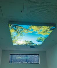
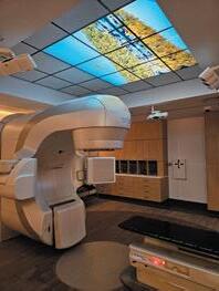
ACIA Electrical Services provides UPS’s, voltage stabilizers, power factor correction units and power filters, to any installation which requires protection. Over 20 years working in the medical industry
Western Water Solutions has partnered with Flowio to deliver Sustainable Building Solutions for commercial and healthcare facilities’ heating and cooling systems.
Our technologies increase asset dependability and performance while lowering operating costs via reduced maintenance, reduced chemical use, and water and energy savings.

Western Water Solutions is a solutions-based company that has a strong focus on customer excellence.
We aim to provide an unparalleled experience to each and every client.
Phone: 0400 704 115
www.westernwatersolutions.com.au

Western Australia. We will achieve this through collaboration, education, and connection.
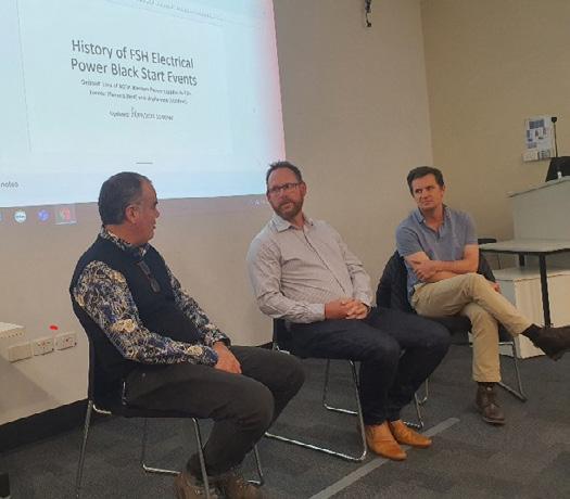
With the politics of an election done and dusted for another year, a panel discussion was held on “Electrical Black Start Testing.” This is a Healthcare Facility Manager’s riskiest activity and one that often gets put aside as being too difficult to perform. Black Start Testing is critical to the ongoing safety of a healthcare facility. I can say from personal experience that when your facility goes black and there is a possibility it will, you must have a tried and tested process for restoring power safely and quickly. We did and it went as expected and no one was placed at risk.
Healthcare Electrical Engineer, Mr Andrew Waugh chaired the panel with challenging topics on
• Western Power’s preparation for a statewide “System Black” event, and what Health Care Facilities will face.
• How to improve your “Black Testing” journey and the lessons learned from routine testing.
• Unplanned electrical power disruption events - a frank discussion of real events and impacts.
Our thanks go to Andrew for an excellent presentation and to RPH’s Mr Phillip Hawkins and the RPH Executive for hosting the event.
September is our conference month. Last year’s conference was very good, feedback rated it as excellent. This year’s was better, I am not sure how one can improve on excellent, but the committee achieved it.
The conference was again held at the Fraser Suites in East Perth and the theme was Replace, Redesign, Renew: The Future of Health Care Engineering.
Conference convenor and committee colleague Jana Simpson created the following synopsis of the event.
This year’s theme emphasises the critical need to innovate and transform health care engineering practices to meet the evolving demands of modern health care. Through a focus on replacing unsustainable and outdated systems, redesigning

processes for efficiency and effectiveness, and renewing our commitment to cutting-edge technology and patient-centred care, we aim to shape a future where health care engineering drives better outcomes for all.
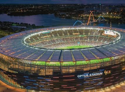
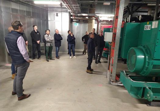
To kick the Conference off, IHEA WA branch provided an exclusive pre-conference, behind the scenes tour at Optus Stadium hosted by BGIS, with special focus on electrical infrastructure and generator power insights by Michael Matrakis from Stantec.
The site tour was followed up with a Sundowner at the Camfield Bar, Burswood for a pre-conference social and networking opportunity.
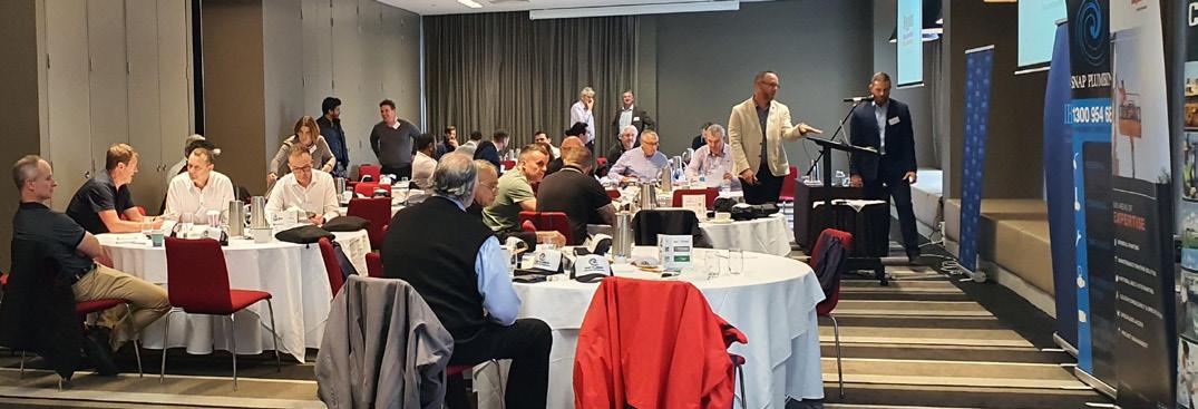
IHEA WA Branch hosted their annual Conference on Friday 6 September 2024 at Fraser Suites, Perth WA.
There were seventeen guest speakers that spoke on topics related to the theme of the day Replace Redesign Renew.


Highlights of the day were:
Amy Wang from EBM Papst and Lars Weber from Siemens spoke about the benefits of Electronically Commutated (EC) fan use in air handling units.
The EC fans:
• Require no VDS drive control and are brushless,
• DC driven and can be retro fitted into AHU systems to replace the belt driven motors.
• Negate any outage as if one fan fails the others take on the load.
• From a maintenance viewpoint they are plug and play, and require very little maintenance other than cleaning.
• A case study conducted at St Vincent’s hospital showed a 32% energy saving when an AHU was fitted with an EC fan system this did not take into consideration lower maintenance costs.
Matthew Wood from SSG Insight discussed asset management data quality and the future use of AI.
Points touched on were:

• AI question sets can be used to predict breakdowns, equipment failure and asset reliability
• Creating predictability from uncertainty by the use of reliable collected data.
Sam Davis from Plexus Engineering’s presented a case study, Turning a bowling alley into a day procedure unit.
• Preplanning is the key especially when converting premises to an alternative use, power demands, planning permission and locations of essential equipment.
• If done well savings of 30% can be achieved when compared to a new build and a decrease in carbon footprint.
Alex Rodger from NDY discussed the looming apocalypse of global warming and its effect on service delivery.
• HVAC temperatures efficiency, and capacity need to be redefined.
• Rain patterns and humidity changes need to be considered for drainage specifications and air flow requirements.
• Electrical maximum demands will increase due to load and equipment running times.
After a nice morning tea of pastries and croissants Dr Surani McCaw from Southland Filtration spoke about Reverse Osmosis (RO) systems designs and their use in Renal and CSSD departments.
We are the electricians of choice for healthcare facilities across WA.
From install & commission to certification & compliance, Foster’s Services is your turn-key solution.
We specialise in delivering medical electrical services for public & private facilities including:
■ Hospitals ■ Medical clinics ■ Day surgeries ■ Allied health
■ Dental
■ Metropolitan & Regional facilities.


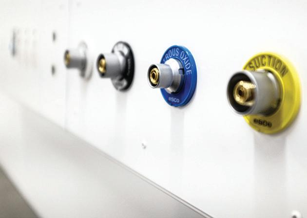


• Two pass RO systems were compared to the use of deionisation resin systems.
• Traditional RO systems were compared to the new advanced systems that can produce a recovery rate of 85-90%.
Ben Gill from Plasma Shield spoke about improving indoor air quality and emission reduction by the use of filtration.
• New improved filters can decrease air borne pathogens.
• You can increase the outside air equivalent through more efficient filtration and circulation.
• Decrease energy consumption by running more efficiently.
• Reduce odours without the need for carbon filtration.
Seyed Safi from Covaris discussed Facility maintenance forecasting and cost modelling.
• Knowing what you have (Correct data).
• How much it costs to service (Preventative maintenance regime).
• How long you will have it (Useful expected life).
• Costs to replace (Forecasting).
David Chokolich from BGIS HFM enlightened us about energy auditing.
• The role of a Certified Energy Manager.
• Replacement opportunities Alternative energies.
• Energy movement away from gas solutions to green energy.
• PVMA Performance Measurement and Verification.
Martin Winship from Nilsen finished off the morning session discussing Electrical Preventative Maintenance.
• The need for regular TEGG reporting to determine maintenance requirements.
• TEGG Pro as an informative dashboard for reporting’
• Surge protection requirements.
• The need to be Vigilant, Informed and Proactive.
After a lunch of pumpkin and feta salad, egg sandwiches and chicken rolls washed down with you choice of juice
Alex Foster from EV Charging Systems spoke about:
• The fast-changing Australian Standards
• Power requirements infrastructure upgrades and maintenance costs to consider.
• The need for systems to be Reliable, Future Proof, User Friendly and Integrated.
Up next Charles Bucknell from CETEC discussed water system designs.
• Circulation is the key to decrease the need for flushing.
• Chlorination is the preferred means of disinfectant.
• Dead legs will result in poor water quality and present circulation issues, avoid elongated branch lines.
• Large storage options are not necessarily the best.

Tanmay Saini from Ziehl mirrored the first talk of the day highlighting EC fan use though this time it was relevant to cooling towers.
• Decreased noise pollution.
• Smaller Carbon footprint
• Better redundancy and vibration sensors linked to determine Preventative maintenance forecasting.
Zachary Browne, Rajeshwaralu Kumaresan and Kane Bailey from Stantec looked into the future speaking about AI innovations future energy saving products and waste management.
• Looking at patronage trends to set building parameters.
• Robotic Cleaning
• AP driven informative wayfinding.
• Radiation of heat sinks located on roof tops during the day.
• Turning commercial kitchen waste into biofuels.
• 3D smart models for preventative maintenance use.
Michale Goodman from Clevertronics illuminated us with the new innovations in emergency lighting discussing:
• Design, Battery Innovation and Efficiency.
• Life cycle and test reporting.
After an afternoon tea of slice and coffee Daragh Maher from Write Solutions discussed the European trends in waste management and Australia’s movement away from single use plastics.
• Waste is now a returnable cost Food Organics Garden Organics (FOGO) strategy.
• De packaging of prepacked food waste, equipment developments.
The penultimate speaker was Octo Moniz from Royal Perth Hospital (RPH) who shared his experiences adapting RPH emergency services and educating staff with regards to emergency response and security issues.
The last speaker was David Chokolich from BGIS who spoke about innovations in training and shared a video clip of companies using virtual reality to train employees to carry out tasks in a safe and controlled environment.
The award for presentation of the day went to Daragh Maher from Write Solutions.
I had the privilege to sit in the audience and absorb what was going on. What a joy it was to listen to these experts. Their messages were enlightening, and some were even a bit frightening. My take home from the event was that Healthcare Facility Managers, Consultants, Contractors and indeed the general public need to heed the messages of change and to act now to ensure that our future environment and society is as healthy and sustainable as we can make it.
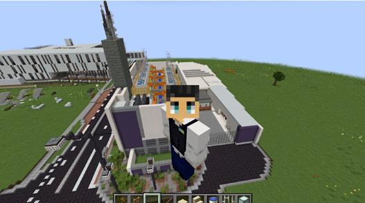
Thanks must go to our convenor, Jana Simpson, and the committee for delivering another superb conference. The Emcee and his dad jokes were kept in check by a vigilant and rigorous timekeeper. The banter between the two was a show in itself. To close the conference, Andrew Waugh, Vice President dived into the world of MineCraft and took us on an extraordinary tour of the Central Energy Plant at Fiona Stanley Hospital.
In October, we will be visiting Plexus Engineers who will be presenting the scenario of Electrification in Healthcare: Powering the Future of Hospital Infrastructure.
In November, we will return to the Queen Elizabeth II Medical Centre to discuss the changes to the long-awaited release of the 2024 Western Australian Guidelines for Health Care Engineering. A few committee members will also travel to Adelaide for the midterm National Board meeting.
In December, we will be celebrating 2024 with our members and guests at our annual Christmas sundowner.
In January 2025, we will all be on a hiatus enjoying time with family and friends over the summer holiday period.
December is only 10 weeks away and it may seem a bit early but on behalf of the Western Australian Chapter, I want to wish all of our fellow IHEA members and their families, a safe and happy Christmas and a prosperous 2025.
Kind Regards
Frederick Foley
WA
Immediate
Past President.


macdonaldconsultancy.com.au macdonaldconsultancy.com.au


Macdonald Consultancy began their partnership with RMIT in 2015 when Donald Macdonald first encountered the CAMS asset life cycle modelling software and met the CAMS development team at RMIT. Donald recognised the game changing nature of this innovative software and its many unique features and was particularly struck by the following:
• CAMS is a versatile system that can host the full range of asset types typically found in a healthcare environment including biomedical, laboratory, research and facilities management assets.
• CAMS helps to ensure end-to-end data integrity through the CAMS hand- held data collection tool and the CAMS cloud-based asset hosting and life cycle modelling data base.
• The CAMS architecture enables data to be hosted in the format that best meets client need and is fully compatible with the full range of commonly occurring asset hierarchies including VBIS, OmniClass and Uniclass.
• CAMS is highly flexible enabling the generation of reports with the content and in the format most appropriate to user requirements.
• CAMS offers the user the ability to model various scenarios to enable the matching of forecast life cycle expenditure with limited budgets.
• CAMS offers the user the ability to categorise asset replacement activities from a variety of viewpoints e.g., risk, criticality, patient impact etc.
• CAMS can present asset data in a way that can be readily understood by lay people.
• CAMS translates technical data into financial information.
• CAMS can assist with the business case for asset replacement by illustrating the linkage between core business and the assets identified for replacement.
• CAMS facilitates effective succession planning through multi- layered password protection, the rigid data base structure and the hosting of data in the cloud.
• CAMS enables the hospital engineering department to more effectively manage the expectations of the executive through the identification of expensive highrisk asset replacement requirements several years in advance.
Being a research organisation RMIT are focussed on developing CAMS to provide ongoing value to our clients and are continually updating the tool to meet our clients’ evolving needs, recent initiatives have included enhancing the functionality of the system, measuring and reporting
the carbon footprint of the asset base and supporting the circular economy.
With the release of the CAMS 2 asset management software system the asset management partnership between Macdonald Consultancy and RMIT goes from strength to strength. CAMS is currently deployed on over 1,000,000m2 of healthcare facilities throughout Australia.
Macdonald Consultancy deliver, as part of our wide range of services, asset data collection and asset data modelling, giving clients single point accountability for data integrity as well as fully supported access to the CAMS software system.
Key to our success is helping clients ensure that their facilities are safe, compliant and well maintained. Macdonald Consultancy has proven experience in healthcare, delivering services such as asset audits, life cycle modelling, asset maintenance reviews, and asset management strategies to a wide range of hospitals, including:
• Mater Misericordiae, QLD
• The Gold Coast University Hospital
• The Alfred Hospital
• Victorian Comprehensive Cancer Centre
Donald Macdonald established Macdonald Consultancy in 2017 as a specialist facilities management consultancy, to fill a gap in the market. To bring robust, research- based consultancy support to the facilities management and asset management sectors. Key facets of our service delivery model include:
• A multi- disciplinary team of directly employed consultants.
• Subject matter expertise in facilities and asset management.
• Thought leadership in facilities and asset management; and,
• An innovation partnership with RMIT.
Macdonald Consultancy’s goal is to help organisations drive down cost and improve quality of their non-core business. Freeing Clients up to concentrate on the reasons that they go to work.
Many healthcare facilities and hospitals around the country have partnered with Macdonald Consultancy, why not join them?
Mission Controls specializes in designing, installing and optimizing building control systems. We prioritize performance and “maintainability”. Our systems are fully documented and fully open via BACnet®, with Administrator privileges are handed over to the client after project completion. We also train customer staff to understand and use the new system, and HVAC principles in general.
Perhaps you have a HVAC system that is not performing to your expectations? We can diagnose and report, to make it work better and usually reduce energy consumption.
Why not start something, before your technical chickens come home to roost?
Contact: Glen Corthine Glen@Mission-Controls.com.au
Richard Ambler Richard@Mission-Controls.com.au


Richard Ambler Mission Controls
Introduction
An existing QLD hospital has 7 operating theatres. The theatres were supplied by 7 small AHUs, which were due for replacement due to their age, and this gave an opportunity to also upgrade the controls. The theatre HVAC system had some problems, for example:
• Poor theatre pressure control
• Poor temperature and humidity control
• Poor reliability
This report sets out the causes of the problems, their solutions and how the solutions were implemented.
Poor theatre pressure control
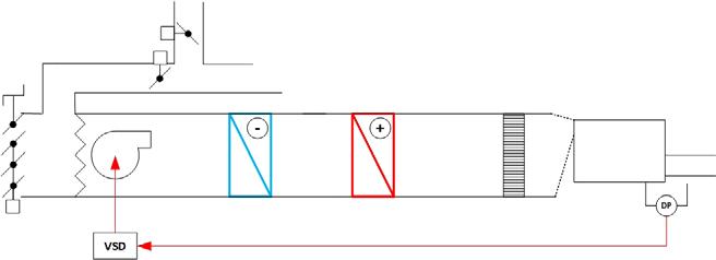
The room pressure was controlled using a conventional fan speed loop using the room pressure as reference:
This operated poorly, with the fan accelerating to maximum speed when the theatre door(s) were left open. This impacted the pressure control in adjacent areas, and upset the control of the heating and cooling coils.
Poor theatre temperature and humidity control
The room sensor was mounted on a wall with an integral temperature setpoint knob. This was subject to draughts inside the wall cavity, heat gains from theatre equipment placed under the sensor and a slow response to room condition changes. The supply air temperature was neither monitored nor controlled, leading to cold and hot draughts at the operating table.
Poor reliability
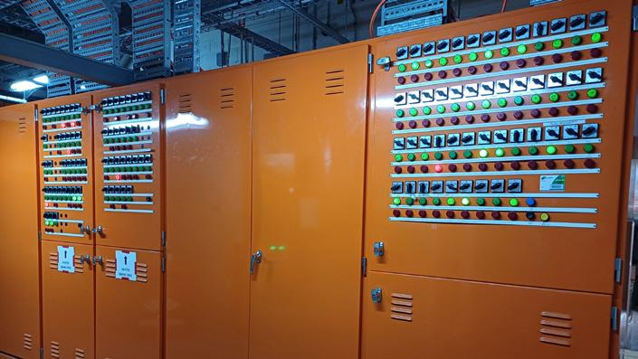
The controls for all 7 theatres were mounted in a large cabinet with a single source of power. The field equipment power was supplied from a single transformer, and all the controls in the panel from a second, single transformer. Single control boards controlled multiple theatres.

A single power problem or controller glitch could thus be catastrophic across multiple theatres.
Only one temperature and humidity sensor was used per theatre; if the sensor failed then the theatre could not be used until it was replaced. This involved gowning-up.
Pressure control by no pressure control
Theatres in practice will always have doors opening and closing, and be left in either state for long periods making pressure control problematic. Rather than chase pressure control explicitly it was decided to treat the whole operating theatre suite as a volume control problem. If the same controlled design volume was maintained to each theatre and their surrounding attendant zones, then the

For over 75 years, Higgins Coatings has been Australia’s premier commercial painting provider. We love what we do and are passionate about delivering the very best results for our customers.
With a commitment to WH&S, quality, and the environment, we stand behind our motto ‘Whatever it takes’, ensuring that every finished product is one of supreme quality.
OUR AREAS OF EXPERTISE
• General painting
• Maintenance painting solutions
• Remedial repairs
• Colour specification and consultancy
• Specialised access
• Project management
Do you want to gain valuable insights, inspirations and WHS tips for your healthcare facility’s next painting maintenance project?
Download our Guide to Healthcare Facility Maintenance and Painting!
Download now

pressure regime as a whole would be stable and maintained. Each AHU was therefore configured as a constant volume unit. This also maintains flow volume as the pre-filter and final HEPA theatre pressure drops increase.
The replacement AHUs had ECM fans which were supplied with a flared inlet cone and a static pressure tapping in the cone. The manufacturer supplied an equation to calculate the fan flow from the cone static pressure. This flow measurement method was used together with a conventional Pitot flow grid to determine the best flow measurement method during commissioning.
The theatre room pressure was measured with respect to the adjacent corridor with a low range pressure sensor installed for information only: the flow of supply air (L/s) to the room was held constant by adjusting the ECM fan speed. The extract fans from all of the theatres were set to run at constant speed to give a specified flow rate. The required constant supply and extract flows to achieve the required pressure regime were tuned at commissioning.
theatre temperature and humidity control
Two combined temperature and humidity sensors were installed per theatre. One sensor is used as control reference at any time, the second is used as a check on the other, and as a back-up in case of trouble. The back-up/reference sensor can be instantly switched via a software switch from the BMS management station, even during an operation.
One temperature/humidity sensor was installed on the theatre wall, and one in the extract duct: the best location for accuracy and response time was noted during commissioning and set as the default reference for control.
The room temperature sensor was mounted on a stainless-steel plate with the sensor tip in free air about 2cm away from the wall. This improves the response time of the sensor, which may be sluggish if a conventional housing is used.
The errors from setpoint of room temperature and humidity are used to calculate an appropriate supply air temperature. The heating and cooling coils are then driven to achieve that supply temperature. Upper and lower limits to the supply air temperature are applied, together with rate-of-change limits, so that surgeons and their staff are never subject to hot or cold draughts.
Seven separate control panels were built to house the controls for the seven theatres. Each panel has two transformers, one for field equipment and one for the panel mounted controller. Electrical and control problems can thus be isolated and addressed, without closing down all theatres.
In the case of communications failure, each controller will continue to run normally. The controllers can still be interrogated by using any laptop and any web browser using a direct connection at the panel.
All the programmable controllers used for this project, and in other hospital areas, use the same controller hardware, which is widely available. The specific control code is held on a programming laptop that is retained on-site, with an open password.
All theatre sensors use conventional 0-10V signal connections rather than communications links; normal hospital maintenance staff can replace them should the need arise.
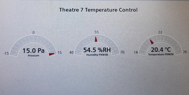
The new controllers are fully integrated into an existing BMS including graphics. This is possible as the new controllers communicate using BACnet, and the new code has been written with this in mind.
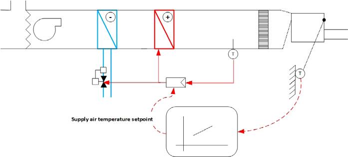
The management of the implementation is worthy of a magazine article by itself. As the reader can imagine, demolishing 7 AHUs, installing new ones together with new control panels and upgrading the electrical supply, in a working hospital, within a narrow time window, was challenging.
The control code was pre-site bench tested. The BACnet integration method was also proved before this project started.
“Smart” valves were used for the CHW coils: these measure and control the CHW flow rate (L/s) so that balance valves are not required, reducing commissioning time.
Each theatre now has an LCD interface, allowing surgical staff to set their own temperature setpoint, and check actual conditions.
Room humidity is generally held within a +/5% band and temperature within a +/-0.5°C band. Reliability has been good; one the main problems has been suppressing electrical interference transmitted via the hospital power supply.
ECM Fan
Electrically Commutated Motor fan
A fan that uses a direct coupled, DC electric motor
With thanks to Dave Duncanson
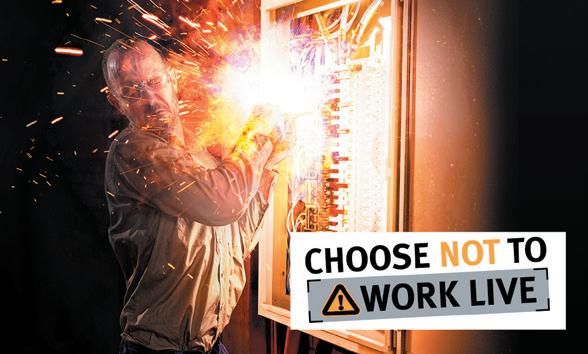

Reducing the risk of ARC FLASH or ELECTROCUTION when testing RCDs saving time & money. Rapid Test utilizes wireless technology to test your RCDs at the DB without removing the escutcheon, no need for working live. Installing Rapid Test into the switch board allows you to test power & lighting RCD’s with the push of a button. All testing is time & date stamped with retest and failure notifications available for easy site compliance management. Data is then uploaded from tablet/mobile to an Asset Portal helping manage your compliance worries with a few mouse clicks.

Seamless management of your RCD / Safety Switch compliance testing through wireless technology. Half your labour costs and improved safety makes Rapid Test a logical choice. CALL US 1300 78 1300 EMAIL US info@rapidtestsystems.com.au


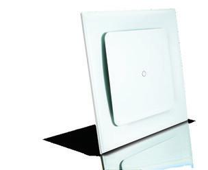


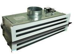
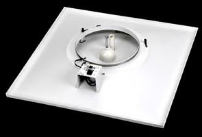
Improved plug-and-play cable and network connectivity.
On-board controller, temperature sensor and occupancy sensor as standard.
All metal construction including face-plate, control disc, foot-mounts and interface cover.

Our next generation of Rickard VAV Diffusers not only provide occupants with optimised thermal comfort, they are also easier to install, and include more features and functionality. These auto zoning diffusers can operate through a BMS or Rickard standalone software, and reduce power consumption by lowering demand on the air handling system.


This paper explores innovative methodologies developed through a benchmarking study aimed at forecasting asset lifecycle and maintenance costs. Central to this effort is the development and application of an Asset Lifecycle and Maintenance Cost Model, rigorously tested across a selection of public sector hospitals. This model employs a detailed bottom-up approach, leveraging the facility’s asset register to accurately forecast maintenance costs, encompassing preventive and corrective maintenance, as well as lifecycle replacement and refurbishment costs. The paper also presents a methodology for determining the forecasted annual cost of utilities for a new healthcare facility.
Introduction
Healthcare facilities require regular and effective maintenance of their physical assets to ensure a safe and secure environment for patients, staff, and visitors. Asset maintenance is a crucial aspect of the facility’s asset management process, involving both planned and unplanned maintenance activities. The lifecycle costs include asset replacement and refurbishment. The primary objective of this study is to establish a cost model to support healthcare facilities in planning, budgeting, and forecasting. The study aims to forecast both capital and recurrent costs to enable lifecycle planning and TOTEX considerations. The findings will serve as a tool for healthcare facilities in their forward planning, including forecasting maintenance and capital expenditures within their Asset Management Plans. The model presented here uses a bottom-up approach to calculate these costs for healthcare facilities. This paper outlines the process for cost modelling and presents the initial findings from the Building & Facilities Cost Modelling (BFCM) for a healthcare facility.
Figure 1 illustrates the process for Building & Facilities Cost Modelling for a healthcare facility. This section presents the steps involved in developing the cost model, which covers a modelling period of 25 years. The Cost Model uses a bottomup approach based on the asset register from the healthcare
facility’s asset management information system to calculate both maintenance and life cycle costs. The definitions of the cost elements are shown in Table 1.
The modelling covers maintainable building and facility assets. The results presented in this paper are based on a recently commissioned hospital with an accurate asset register.
The first step in the cost modelling of a healthcare facility is to identify the list of assets which is used for the bottom-up modelling approach. The required asset data are:
1. Asset Details: asset id, asset name, asset classification as a minimum plus additional asset details if available (e.g., manufacturer name, model number …);
2. Asset Lifecycle Details: in service date, purchase cost / replacement value; and
3. Asset Condition Assessment (if available): observation date, Condition Rating, Current Usage, Operating Environment, Criticality. If asset conditions were not available, asset condition was assigned based on the age of the facility.
An asset reference data library is required for building and facility assets to enable the modelling of maintenance costs for healthcare facilities. The reference data have been
developed for all asset classifications used in the hospital’s asset register. This information drives the calculation of maintenance costs and includes the following:
1. Identifying the maintenance strategy for assets with applicable asset classifications. All assets will be identified as requiring planned maintenance or unplanned maintenance.
2. Price Book: This important reference data provides the current replacement value for assets. If the healthcare facility asset register has accurate purchase cost/ replacement value, these values will be used in the calculation of refurbishment and replacement costs. If cost data is not available, the average price from the price book for the applicable asset classification will be used.
3. Life Expectancy (years): Provides the expected life by asset classification. Assets will be replaced when they reach the end of their expected life (see Table 2).
4. Planned Refurbishment (years): The expected frequency of the refurbishment by asset classification (see Table 2).
5. Planned Refurbishment (%): The percentage of the asset cost required for the planned refurbishment (see Table 2).
The first cost component in the model is developing the bottom-up budget for preventative maintenance. This includes calculating the preventative maintenance cost for all maintainable assets using the following steps:
1. Allocate Maintenance Type to each asset: At the end of this stage, each asset will have a type of maintenance allocated (planned or unplanned) based on the asset reference data library.
2. Develop Asset Maintenance Plan: This stage involves developing an Asset Maintenance Plan for all assets identified with a planned maintenance type, based on the developed Planned Maintenance Service Plans. The maintenance service plans are aligned with the statutory maintenance requirements for the applicable asset classification. At the end of this stage, the Asset Maintenance Plan developed will contain a detailed maintenance schedule and resource requirements.
3. Indicative Costs for PM Delivery: Develop an annual PM maintenance cost forecast for all assets in the site-specific asset register. This includes calculating the annual cost of PM delivery based on the estimated duration and hourly
rate of the required resource. PM delivery costs include trade resource hours, work quality checks, administrative support, supervisor/building manager, and spares cost.
The second cost component in the model is developing the budget for corrective maintenance, which is estimated based on the asset condition across the site using the following steps:
1. Rate of CM/PM: Corrective maintenance annual labour hours are estimated as a percentage of calculated PM labour hours based on the asset condition.
• The ratio for CM labour hours as a percentage of PM labour hours is estimated at 30.3% for new assets/ facilities. This ratio was identified from actual data provided by a maintenance services provider over a three year period for a hospital less than 10 years old.
• The ratio for CM labour hours as a percentage of PM labour hours is estimated at 40% for assets/facilities with average asset condition.
• The ratio for CM labour hours as a percentage of PM labour hours is estimated at 60% for assets/facilities with poor asset condition.
• The CM/PM labour hourly rate is 125% (on average, the hourly rate for corrective work is 25% higher than the preventive work hourly rate).
2. Indicative CM Material Costs: The estimated cost of materials for CM work is estimated at 20% of the CM labour hour costs.
3. Indicative costs for delivery: Develop an annual corrective maintenance cost forecast for all assets in the site-specific
asset register. CM delivery costs include trade resource hours, work quality checks, administrative support, supervisor/building manager, and spares cost.
The third cost component in the model is the Life Cycle Replacement cost which is calculated for all assets included in the site-specific asset register based on the following steps:
1. Life Expectancy (years): Expected life of each asset is identified based on the asset classification. The expected life for the applicable asset classification is identified in the asset reference data library.
2. Installed date and Replacement Value: Identify the installed date and asset replacement value from the asset register. If the data is not available, identify the installed date by consulting healthcare facility asset managers or the age of the facility. The replacement value can be estimated based on the asset classification and the replacement value for the applicable asset classification as identified in the asset reference data library. If the healthcare facility asset register has accurate purchase cost/replacement value, these values will be used in the calculation of refurbishment and replacement costs.
3. Annual Replacement Cost: Develop an annual life cycle replacement cost forecast for the life of the assets for the site-specific asset register. For the 25-year Cost Modelling, assets may be replaced multiple times based on their expected life.
The last cost component in the model is the Life Cycle Refurbishment cost which is calculated for all assets included in the site-specific asset register based on the following steps:
1. Refurbishment Frequency (years): The refurbishment frequency of each asset is identified based on the asset classification as identified in the asset reference data library.
2. Installed date / Refurbishment Value: The installed date is identified from the asset register, if available. If the data is not available, the installed date is identified in consultation with healthcare facility asset managers or the age of the facility. The refurbishment value for each asset is a percentage of the replacement value of the asset based on the applicable asset classification as identified in the asset reference data library.
3. Annual Refurbishment Cost: Develop an annual lifecycle refurbishment cost forecast for the site-specific asset register. For the 25-year Cost Modelling, assets may be refurbished multiple times based on their refurbishment frequency.
This section presents a methodology for determining the annual cost of utilities for a new healthcare facility, based on expected electricity, gas, and water usage. It highlights research conducted to compare the new facility with similar recently commissioned hospitals in terms of floor space and number of hospital beds to access their current utility usage data.
To estimate electricity, gas, and water usage, the best solution was found using the NABERS (National Australian Built Environment Rating System) reverse calculator. This simple and reliable government-supported tool provides an open-source benchmark for predicting energy and water consumption for hospitals. The calculator uses actual data from annual energy and water consumption from other Australian hospitals to predict annual electricity, gas, and water usage.
The following parameters are required by the NABERS reverse calculator:
• Location: Location of the hospital, specified by the postcode.
• Occupied Day Beds (ODB): number of occupied bed days is one of the key data inputs required by the NABERS reverse calculator for Energy and Water for hospital buildings. Occupied bed days refer to the number of days in a year that a hospital bed is occupied by a patient.
• Percentage Breakdown of Energy Consumption: The type of energy consumed by a building for major processes like HVAC and plantroom equipment, (Commonly used as Electricity and Gas) expressed as a percentage ratio.
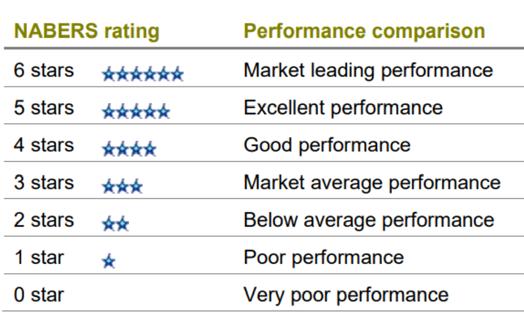
• Expected NABERS Star Rating: The reverse calculator uses NABERS ratings that are expressed as a number of stars. The more stars in a NABERS Energy rating, the lower the environmental impact of the rated premises. This means that higher rated buildings are more efficient in energy usage compared to similar size and industry buildings. Figure 2 Efficiency Star Rating shows the NABERS Star Rating.
To ensure an accurate estimate for the subject hospital, the historical electricity usage of two similarly sized, recently commissioned hospitals was tested using the NABERS reverse calculator. The results for a 4.5 NABERS Star rating, with an electricity-to-gas consumption ratio of 80% to 20%, showed over 95.5% accuracy when compared to the historical data of the two test hospitals. Based on these tests, the energy and water consumption for the subject hospital was estimated using the NABERS reverse calculator. Table 3 shows the predicted average consumption for the subject hospital. The costs of electricity, gas, and water usage were then calculated based on the respective unit costs.
Cost model was developed for the subject hospital building and facility assets. The modelling period was 25 years. However, it can be adjusted to any modelling period as required to align with health entities’ requirements, such as their asset management plan reporting requirements. Table 4 shows the modelling results for the subject hospital.
It is important to note that the cost model may underestimates full amount required for maintenance and capital costs of the hospitals for the following reasons:
1. The modelling only covers maintainable building and facility assets recorded in the asset management information system. If assets are not recorded in the asset management information system, the modelling underestimates the required costs across all maintenance categories.
2. The modelling excludes fixtures, fittings, furniture, and equipment.
3. ITC & digital assets were excluded from the modelling.
4. Fleet, food services, and laundry services assets were also excluded from the modelling.
5. Biomedical assets were not included in the modelling.
The cost models exclude the following cost components:
• Replacement of buildings at the end of their useful life.
• Upgrade work.
• Grounds maintenance.
• Soft services.
In conclusion, the Asset Maintenance and Lifecycle Cost Model represents a significant advancement in forecasting asset lifecycle and maintenance costs for healthcare facilities. The study employed a bottom-up approach to develop the cost model, which was applied to selected healthcare facilities. The model calculates preventive and corrective maintenance costs, as well as lifecycle replacement and refurbishment costs over a 25-year period. This paper presented initial findings from the cost model for a sample hospital, along with a methodology for forecasting the annual utility costs for a healthcare facility. The cost model has the potential to assist healthcare facility
managers in their forward planning by providing accurate expenditure forecasts within their Asset Management Plans.
1. Life Cycle Costing Standards, Health Infrastructure 2014
2. Rawlinsons Construction Cost Guide 2024
3. ATO Life Cycle Time Expectations TR 2016/1
4. Estimated Useful Lives of Depreciable Hospital Assets, American Hospital Association, 2018 Ed.
5. 2011 Architectural Manual - Expected Useful Life Table
6. Updated Buildings Sector Appliance and Equipment Costs and Efficiency, U.S. Department of Energy
7. NABERS Energy and Water for hospitals: Rules for collecting and using data.
In a groundbreaking leap for Healthcare innovation, Westmead Hospital is now home to a state of the art Compressed Medical Air System and a newly built stand alone plant room, a turnkey project meticulously executed by Goldman Plumbing Services, redefining the standards of medical infrastructure.
With the project's design parameters set and overseen by Crowley Consulting, Goldman Plumbing's Engineering team has not only replaced but transformed the compressed medical air system at Westmead Hospital. The result is a cutting-edge system that flawlessly integrates functionality and efficiency, signalling a new era in Healthcare infrastructure. Importantly, this transition occurred seamlessly with the new system installed and commissioned without any disruption to the Hospital's Compressed Medical Air supply.
The system boasts four Medical Compressed Air Compressors complete with advanced heat of compression dryers, featuring two water-cooled and two air-cooled compressors, ensuring 100% redundancy. This combination guarantees a continuous and dependable supply of medical compressed air.
With a firm commitment to sustainability, the chosen Atlas Copco ZT37VSDFF generators incorporate variable speed drives, unlocking energy savings of up to 50%. Integrated heat recovery features contribute to eco-friendly operations by utilising up to 94% of compression heat for drying the desiccant filters, eliminating the need for additional energy sources

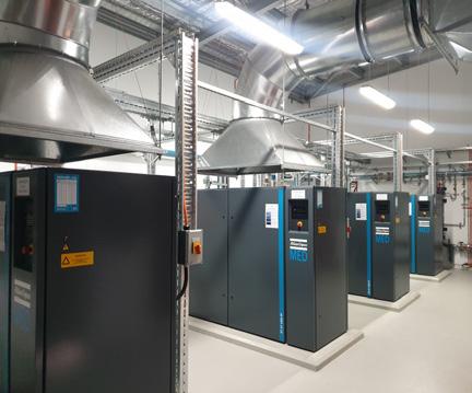
The design incorporates a fully automated room ventilation and compressor cooling system. The systems control panel regulates fan usage based on operational room temperatures, optimising energy consumption for maximum efficiency and cost-effectiveness.
A dedicated Medical Air Alarm System receives digital signals from compressors and pressure sensors, promptly alerting system operators to any critical alarms or warnings. Real-time insights into operational parameters are provided through Building Management System connectivity with high level interface.
The Medical Compressed Air Plant and Mechanical Services control centre comprises four individual modules, showcasing a commitment to reliability. Each module is dedicated to supplying specific plant and equipment, allowing the system to fully operate during maintenance periods or partial system failure.

Goldman Plumbing's holistic approach extends beyond the medical compressed air systems design and installation. Goldman Plumbing also designed and constructed the dedicated stand alone plant room. Not only does this approach provide a single point of accountability for the entire project, it also ensures seamless translation of the systems design intent into fully functional and reliable Healthcare infrastructure.
The Compressed Medical Air System not only meets but surpasses all relevant Australian Standards and modern Healthcare facility expectations. This project signifies a stride towards excellence in medical facilities, where innovation meets reliability and the future of healthcare infrastructure is now a reality.


Mitigate risk and downtime for your healthcare facility through proactive maintenance of HVAC, Fire and Electrical systems. Regular servicing will help to eliminate and spot any potential problems before breakdowns.
At Grosvenor Engineering Group (GEG), we understand that the comfort of patients and doctors is paramount in hospitals and clinics. The reliable operation of cooling equipment supporting critical MRI and other medical equipment cannot be compromised.
At GEG, we have over 25 years’ experience providing end-to-end solutions to many healthcare facilities. Our technicians proactively maintain operational technical assets, ensuring your patient-care continues as usual.
www.gegroup.com.au

Simon Witts
VA Sciences
The white paper on the integration of heat pumps into existing hospital systems examines the challenges and necessary adaptations for replacing traditional gas-fired systems with heat pump technology during the electrification process.
Heat pumps, essential for generating hot water, have operating parameters that differ significantly from conventional systems, requiring modifications to existing infrastructure like risers, pumps, and main distribution systems to handle lower temperatures and higher flow rates.
The transition is particularly complex in healthcare facilities where complete re-piping to optimise heat pump performance may be impractical, often leading to sub-optimal operation.
The document underscores the importance of distinguishing between heating and domestic hot water systems, as they operate at different temperatures, which impacts their energy efficiency and overall system performance.
The all-electrification process in most instances requires the use of heat pump based technologies to generate the hot water. When considering system replacements, the installed systems in existing hospital systems have different requirements.
The integration of heat pumps into legacy systems is not just a case of swapping one heat source for another. Heat pumps invariably have different operating parameters to “traditional” gas fired heating water and domestic hot water systems. These parameters are not always compatible with the embedded infrastructure within an existing facility. When swapping gas for electricity using heat pumps the design needs to consider the system and its operation, not just the swapping out of the heat source.
If the design parameters are altered to suit common heat pump performance specifications (lower temperatures and higher flow rates), then it is likely this will result in changes to the existing infrastructure risers, pumps, and main distribution. So, when considering the integration into an existing healthcare facility it may have to be accepted that in most buildings and systems the heat pumps will be operating sub-optimally as it may not be practical to completely re-pipe the existing systems in the buildings to accommodate the optimal flow rates and temperatures of common heat pump systems. It may also introduce other factors as increased infection control measures.
The distinction between heating and DHW is important as the different temperatures mean that the coefficient of performance (CoP) of the two systems can vary significantly. Design conditions for example, at 3°C ambient, the coefficient of performance (CoP) of a heat pump supplying 60°C DHW is around 3.5. For an LTHW system at 80°C and a return temperature of 60°C the CoP is closer to 2, i.e., much less efficient in the use of energy to create heat.
Choosing system appropriate heat pump technology, able to provide the correct temperatures and flow rates buildings should not present too much of a challenge for competent healthcare building services designers, as they have full control over the primary and secondary water circuits, incoming power requirements and should be fully aware of the functions undertaken in the building.
Swapping gas out of existing facilities is a very different proposition….
Estimating the demand
In most hospital facilities the systems that serve the buildings have evolved over time starting from an initial coherent design and slowly morphing into systems that have been extended, cut back, re-purposed. The result of this evolution is the building systems are often performing in a manner distinctly different from the original design parameters. Establishing the required duty is the first challenge in retrofitting a heat pump.
The second challenge in retrofitting a heat pump will be the availability of power from the local plant level mechanical switch board. When the system uses gas as the primary thermal fuel, the mechanical switch board (MSSB) only supplies the power to the pumps for circulation and controls to enable the equipment to function. When a heat pump is used to replace the gas appliance, the thermal energy is required to come from the electrical supply. Most existing MSSBs will not have sufficient spare capacity to feed the new heat pumps, and in a large installation it is equally unlikely that the sub mains supplying power to the plantroom will also not have enough spare capacity to accommodate a large heat pump installation without upgrading. There can also be knock on effects on the emergency power supplies to the plantrooms depending on whether the heat pumps are deemed a critical service.
Heat pumps need space, and lots of it.
A 200kW gas boiler needs around 1.5m² of floor space for the boiler and maintenance access. A 200kW water to water heat pump would need 12.2m² in the plantroom and 8m² of heat rejection outside of the plantroom. A 200 kW air to water heat pump would need 24m² and be located outside the plantroom.
Solutions to all the above can be found with time and money, the rest of the limitations come down to basic thermodynamics so...
What are the technical limitations with boiler replacement heat pumps.
What are the technical issues in achieving an 80/60°C boiler replacement heat pump?
The battle with natural gas is over (at least in Victorian healthcare) a comparison of emissions of electrically powered solutions must have a new benchmark.
Electricity will be the fuel into the short to medium term, the grid is provided with power from renewable and nonrenewable sources. Under power purchasing agreements, the
green power is sold separately from the non-renewable power, thus from the grid it is possible to be allocated green power only. Having solved the emissions, the green power is limited, and the best use of this then allows other facilities to benefit from the green power available.
The new benchmark becomes to maximise the lifetime COP of the solution. Resistive heating; the simple, reliable and cheap solution has a COP of 1.
When all electricity is zero carbon, then the only environmental impact is the leakage of the refrigerant. Currently, where the greenness of the grid is a point of debate, these emissions need to be balanced against the energy efficiency of the overall system.
In the following paragraphs there are several factors that have been necessarily glossed over as regards the details of the heat transfer etc, most of these are additional small losses that would need to be added to get the actual performance of any real-world system.
The refrigeration cycle is the same for heating as it is for cooling, the term reverse cycle comes from a valve that swaps the condenser and the evaporator flows and allows one compressor to use either heat exchanger as the condenser, and the other as the evaporator.
Thus, the plot on a pressure-enthalpy diagram is the same for an air conditioner and a heat pump.
The conventional refrigeration cycle on a P-H diagram looks something like this.
The P-H diagram shows the energy, kJ per cycle, the refrigerant circulation in kg/s is required to resolve the heat transfer in terms of kW of heating.
There are two heat exchangers in the cycle the evaporator represented by the lower blue horizontal line where the saturated liquid evaporates to saturated vapour. And the condenser the upper red line where superheated vapour cools

to saturated vapour and subsequently condenses to a mix of mostly saturated liquid with some saturated vapour at a high pressure.
The horizontal lines are at a constant pressure and the process is boiling to the right and condensing to the left. For a given pressure boiling occurs at a constant temperature. The lines of the diagram are the conditions inside the pipes, the temperatures available to the heating system depend on the coils or plates of the evaporator and the condenser, the size and arrangement of the heat exchangers determine how close the air or water temperatures are to the refrigerant temperature.
The height of the vertical axis relates to the difference in pressures in the condenser and the evaporator.
The difference in pressure between the cold side and the hot side needs to be provided by a compressor that is available using reliable technology. The Pressure Axis on the P-H diagram is always logarithmic. A small change higher up the pressure axis is very large in comparison to the same change lower down.
A small amount of ‘superheat’ (extension to the right from the saturated vapour line) is necessary to make sure that liquid does not enter the compressor.
Compressors are being pushed to deliver higher differential pressures, there are challenges in this for the compressor and the quality of the pipework assembly. The overall build quality required for the complete system is related to the absolute pressure in the system, with higher pressures come the need for better joints to prevent leaks. The higher the pressure the greater the chances of equipment failure if the equipment is not regularly maintained.
The difference between the evaporator pressure and the condenser pressure (plus the amount of super heat) need to match both the temperatures required from the hot and cold sides. With boiler replacements these are fixed further apart than normal, the hot side at 80°C and the cold side at winter ambient temperatures.
The near vertical line to the left is the operation of the expansion valve, these have become much more sophisticated in recent times. They regulate the flow through the circuit and allow the pressures to be maintained at the target values in the condenser and evaporator. The slight inclination of the line is the parasitic thermal losses at this point in the circuit.
The top of the curve is the ‘critical point’ the pressure above which there is no latent heat of evaporation, above this there is no liquid to vapour transition. Substance in this region
is referred to only as fluid. There is also a specific critical temperature for each substance.
Conventional refrigeration circuits are subcritical, that is the entire circuit is below the critical pressure.
The curve to the left is the saturated liquid condition where the substance is completely liquid at the boiling point. The curve to the right is the saturated vapour line where the substance is completely vapour at the boiling point.
For pure substances and azeotropic blends the transition from saturated liquid to saturated vapour is a horizontal line from the left side to the right. The latent heat of vaporisation is the property that determines the length of the line from the left to the right of the curve.
Critical temperatures for some refrigerants used, or capable, of operating in the 80°C condenser range are shown below.
The COP for the system is the ratios of the enthalpy for each of the parts of the cycle (accounting for the compressor efficiency), for heating this would be the horizontal length of the red line divided by the horizontal length of the green line divided by the compressor efficiency.

The external ambient design conditions for a heating system would be more onerous than for a DHWS system.
The heating systems are likely to need to be able to run 24/7 (in the winter), and the maximum need for heating would be coincident with the coldest ambient. Heating systems would need to work at the design ambient for critical systems (possibly with a margin for climate change).
However, the usage of DHWS is normally low in the middle of the night and all heat pump systems for DHWS would have storage. Thus, it is acceptable to do some of the following:
• Delay the recharge until the COPs are more favourable.
• Run the system with a reduced rate of recharge.

DHWS systems could be designed for, carefully considered, less onerous external design ambient temperatures.
Most of the heat must come from the air. Heat pumps are devices that upgrade the available heat (they expand temperature differences making the heat more useful) they do not produce the ‘heat’ just move it from a cold source to a hot one.
All refrigeration cycles (including heat pumps) need two heat sinks one ‘cold’ the other ‘hot’. Regarding the cold side, unless there is a low-grade waste heat source from another reliable process, this would normally be the ambient atmosphere.
To transfer heat out of the cold source the refrigerant in the evaporator must be at a lower temperature than the cold source temperature (ambient air). This, for each given location, fixes the lower horizontal line in the P-H diagram.
Two illustrate the source of the heat, the diagram is of a two-stage system. Which is currently the most likely solution for a boiler replacement heat pump, it illustrates that the number of kW going into the system at the cold side is only slightly less than the number of KW that is transferred at the hot side. The additional kW coming from the ‘work done’ by the compressors being added to the heat in the system.
The COP of this system would be:

Carbon dioxide has become a common refrigerant for DHWS systems, yet its critical temperature is only 31°C. With a conventional refrigeration cycle the hot side would be limited to something like 25°C to get a reasonable enthalpy difference across the saturation conditions.
This application uses a transcritical cycle, where the evaporator operates in the subcritical region as normal, and the hot side (no longer actually a condenser as there is no liquid/vapour transitions) operates above the critical point.
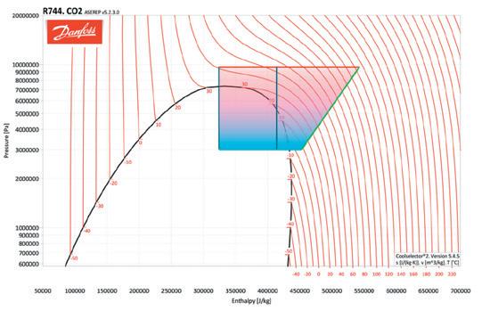
Outside the saturation envelope the temperatures (isotherms) are no longer horizontal and changing enthalpy at a constant pressure means a related change in temperature.
This temperature change is dependent on the water return temperature in the hot side.
The problem is the DHWS system is not designed to lose heat into a process, heat losses at all points in a DHWS are parasitic.
If the water return temperature is too high (say 55°C in the case of CO2 at 100 bar) then the expansion of this will still be mostly liquid (at 30 bar) this is illustrated in the diagram by the central vertical line. As can be seen the CoP at this point is very low, and possibly less than unity.
To get the best CoP out of a CO2 heat pump (in DHWS applications) the cold feed needs to provide the lower temperatures at the hot side. The DHWS systems must be arranged to heat the coldest water last and produce the lowest temperature after the ‘condenser’. This is illustrated in the outer loop on the diagram.
What does the solution look like now?
Manufacturers are using cascading heat pumps with different refrigerants to achieve a low-grade heat source with an air to water heat pumps feeding into a water to water heat exchanger to get the standard boiler temperatures. This solution is practical and provides an improvement against resistive heating, even with a low nighttime temperature. Typically, as the ambient rises, the cop of the first stage increases vastly, thus providing a real alternative to resistive heating.
We can achieve the 80/60 and thus reuse the existing secondary systems and pipework. The CoPs will not be that great as this would most probably be part of a cascading system and each system would have a compressor. The total number of kW input would be higher than if a single stage system was practical.
But this will only ever be a Band-Aid for ageing buildings. New buildings will be built around the most efficient lower temperature heat pumps.
Looking at the available refrigerants there are quite a few capable of operation sub critical cycles with a hot side of 80°C. The number of stages and the resulting CoP aside it is possible to do, with either a single machine or a cascade of two heat pumps.
The question becomes what is the incentive for manufacturers to concentrate on this solution? There is no need for solution in new buildings as the more efficient lower temperature machines that can provide cooling, as well, would be the obvious choice. The other building components would be designed around these. So, these would only be for existing building stock, many of these would continue with gas fire plant for some considerable time. For many the other installations a shutdown for a complete refurbishment including the necessary pipework and coil upgrades in order to work with the new temperatures is a viable option especially if the refurbishment is undertaken with other substantial changes in the building, such as change of use. In addition to this, in the northern hemisphere many heating
systems have been designed using condensing boilers in the 40 to 50C range, these existing systems are well suited to a boiler / heat pump swap without much in the way of alteration. This leaves only buildings (or sites) that have a specific need to move away from gas, that also cannot go offline for an extended period. So, it will come down to is this there a large enough sector for manufacturers to specifically focus on? Our feeling is no.
Physics means it is not practical to remove a boiler and plug in a heat pump in its place. There is a practicality gap and as you increase in size from systems that are measured in kW, to those measured in MW, and that practicality gap becomes exponentially larger the bigger the system becomes.
In Australia, building services engineers will be working with heat pumps available now and towards solutions that involve multiple machines with different strengths and weaknesses, and each site will have a bespoke solution driven by the understanding of its history and the skill of the individual designer.
Resilient Buildings Is your air resilient against mould, odours, viruses, bacteria and bushfire smoke?
Bushfire Smoke
Best in class smoke odour removal at 97.5%
Removal rate 3x better than charcoal filtration
Viruses & Bacteria
Up to 99.99998% destruction rate
Achieve IRMM with ASHRAE 241
Peer Reviewed at 99.999% destruction rate
Reduce humid outside air to 2 5L/s/p under AS1668 2
efficacy destroying VOC and virus size particles bio-HEPA™ technology
Plug-and-Play Platform
true performance
Designed to retrofit or integrate into HVAC, inf rastructure benefiting plant size or efficiency
Scalable, High-Capacity
modular design allows efficient integration into HVAC plenum, duct or plantroom for small to large-scale application
NCC & AS1668.2-2012
exceed standards, earn WELL , LEED, NABERS & Green Star rating with no impact on occupant comfort or HVAC performance1
HVAC integrated design enables custom air distribution pattern to suit each space Superb Air Distribution
Low Energy Consumption
Lower pressure drop, lower fan power and energy
Ben Gill Plasma Shield
Since the days of Louis Pasteur and nineteenth century France, the global scientific community have known that bacteria and disease are linked.
Jump forward a century and in 1962 Riley, Mills et al succeeded in demonstrating airborne transmission of tuberculosis (TB), the first important disease to be scientifically accepted as airborne.
In modern times, the scientific and medical community recognise the importance of using decontaminated air in high-risk environments. Simply put, it is why state-based engineering guidelines mandate the use of HEPA standard filtration in operating theatres.
Yet despite modern hospitals consistently dealing with low immunity patients in oncology wards, neo natal areas and recovery rooms, HEPA standard filtration is rarely installed in these moderate risk areas.
As every experienced hospital engineer knows, conventional HEPA filters are extremely dense, with tiny holes for air to pass through.
This reduces air flow substantially and drives up fan energy. Install enough HEPA filters and the fans quite literally can’t push enough air through the zone and compliance falls away.
So for many years Hospital Engineers have been left with a dilemma: they know that airborne infection risks are real – they know that many patients in moderate risk areas will suffer if infected - yet they haven’t been able to expand HEPA filtration without crippling the HVAC system, or conducting a major upgrade of the air distribution system.
So instead, engineers resort to extreme amounts of outdoor air to try and dilute as many contaminants as
possible, without really knowing how effective it is and paying an enormous energy and emissions penalty.
That was the situation faced by every modern hospital until recently.
Thankfully, the Adelaide Women’s and Children’s Hospital have proven that hospitals now have the choice to achieve HEPA standard filtration without upsizing their fans or ductwork.
The Adelaide Women’s and Children’s Hospital implemented Plasma Shield into their recovery suite and importantly the
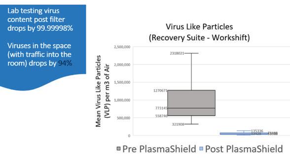
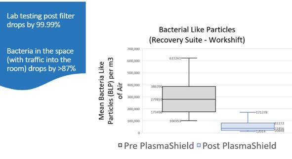
results were recorded and assessed by researchers from the University of Adelaide. Their independent report confirmed that;
• Measurements after the Plasma Shield confirmed the achievement of the HEPA standard filtration efficiency of 99.97% for particles of 0.3 microns; and
• This implementation was achieved without upsizing the fan and ductwork system, due to the lower pressure drop of the Plasma Shield system.
Independent analysis showed that notwithstanding the potential of close-range contact, the infection risk mitigation of this air treatment was equivalent to all staff wearing masks for their entire shift.
In the charts below, you can see the data that underpinned the results. For virus like particles:
• Before the Plasma Shield was operating, a MERV 13 filter was in place and the average virus like particle count was 773,145 per cubic metre of air and the maximum count was above 2.3 million.
• After the Plasma Shield was operating the average virus like particle count was 43,816 per cubic metre of air and the maximum count was below 136,000.
And how much has that cost you? Power bills?
Spoiled produce?
Unnecessary Cool room checks?

T-TEC Wireless data logger with a temperature sensor going into the cool room and a door switch sensor can give alarms that can be seen or heard locally and remotely via a phone app. The effect and duration is clearly seen on the graph and statistics. Contact us for a quote for the TempReport System.
Temperature Technology 105 Anzac Highway, Ashford SA 5035
Tel: 08-8297 7077 Email: sales@t-tec.com.au
For bacteria like particles:
• Before the Plasma Shield was operating, a MERV 13 filter was in place and the average bacteria like particle count was 279,859 per cubic metre of air and the maximum count was above 622,000.
• After the Plasma Shield was operating the average bacteria like particle count was 37,456 per cubic metre of air and the maximum count was below 172,000.
To further test the capabilities of the Plasma Shield solution, independent testing has also been completed in a clean room setting.
ASHRAE, the US based, world leading authority on HVAC have now published the work of Dr Timothy Lau and Dr Martin Belusko , confirming that in a clean room setting:
1. The Plasma Shield system demonstrated a single pass particle removal efficiency of 99.97% for ambient air particles of 0.3 microns, similar to conventional HEPA filters;
2. When operating as a clean room filter, the Plasma Shield system was able to achieve a recovery time of 19 minutes when tested to ISO 14644.1 and ISO 14644.3 respectively, consistent with what HEPA would achieve; and
3. That the Plasma Shield was able to achieve a zero count of Colony Forming Units (CFU) per cubic metre of air for a range of bacteria and fungi, indicating effective microbial removal.
Importantly, HEPA filters work by proxy, they stop unwanted contaminants based on particle size. Plasma Shield instead directly destroys harmful contaminants, furthering its applicability for settings such as recovery suites and oncology wards.
With this proven technical advance Hospital Engineers now have a series of options to improve the health of the air in their moderate risk areas;
A. Upsize the air handling units and duct work at great cost, inconvenience and delay, then expand conventional HEPA filtration; or
B. Continue to use copious amounts of outdoor air to dilute contaminants, burning enormous energy, emissions and costs; or
C. Use Plasma Shield Bio-HEPA filtration and achieve equal or above the filtration efficiency of 99.97%, achieve microbial destruction (zero CFU), with very little changes to plant, equipment and energy use.
The authors respectfully note that the only option that is no longer available, is to knowingly expose our patients to harmful airborne contaminants…
How is electrification transforming healthcare?
Our webinar, “Electrification and Healthcare Transformation,” will be a 45-minute session featuring a global panel of healthcare leaders and technology experts discussing the latest trends revolutionizing healthcare facility operations and care delivery.
What You’ll Discover: Register now!
Learn how leaders leverage electrification to address decarbonization, enhance resilience, and improve efficiency.
“The Rise of the All-Electric Hospital,” our new whitepaper with a walkthrough of key steps and technology selection for healthcare facilities. 2 Whitepaper Launch:
Interact with experts ready to answer your questions live or through follow-up communications.
Data-driven Asset Maintenance
Critical Power and Energy Management
Security Management
Electrify and Optimize Energy Sources
Project Master Planning and Delivery Optimization
Clinical Space Management
Integrated Patient Experience
Integrated Building Operation Platform
Electrification and Digitization Register now!
Sustainability and Decarbonization Strategies
EcoStruxure™ for Healthcare
Enabling the healthcare facility ahead of its time.
Discover more se.com/healthcare


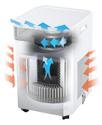
“The complexities of today’s world require solutions of greater sophistication and creativity than ever before”


Our role is to provide the vital controlled environments, of our clients, with comprehensive solutions, testing regimes and performance requirements.
• HEPA Testing
• Clean Room Validation
• Isolation Rooms
• Surgical Suites
• IAQ Assessments
• Filtration Assessments
• Biological Cabinet Testing
• Fume and Extraction Hood Testing

Our role is to provide expert solutions in post-damage event scenarios, developing strategies and recovery plans through comprehensive contaminant assessments and management.
• Mould Impact Assessments
• Escape of Liquid Assessments
• Fire, Soot and Char Assessments
• Asbestos Assessments
• Bacterial Assessments
• Chemical Contamination Assessments

Our role is to provide our clients with best practice risk-based solutions to effectively manage health and hygiene hazards within the workplace and community.
• Hazard Identification and Quantification
• Hazardous Chemicals
• Hygiene Management Systems
• Corporate Health and Hygiene Risk Management
• Incident Investigation
• Fitness for work
Introduction
Adrian Michaels FM Asset Management / BGIS
The health care industry must play a vital role in achieving net zero emissions and mitigating the effects of climate change. There are many challenges present when it comes to achieving net zero in healthcare however there are also practical steps that organisations can quickly adopt to meet them.
Net zero is a state of balance between the amount of greenhouse gas produced and the amount removed from the atmosphere (Energy Savings Trust 2021). Achieving net zero represents the most critical step in addressing climate change and reducing greenhouse gas emissions to levels that the planet can sustain. Furthermore, by curbing emissions and stabilising the climate, we can assist communities and ecosystems in adapting to these changes by lessening the severity of their impacts. Together, we can address this shared challenge and construct a more sustainable future for everyone.
There is an increasing need to achieve net zero emissions within the health care industry. Firstly, the greenhouse gas
(GHG) emissions footprint of the Australian health care industry is significant, measuring 7% of our national total with a large portion (63%) of that total coming from the hospital and pharmaceutical sectors (Malik, Lenzen, McAlister, et al. 2018). Secondly climate change poses a significant threat to public health due to increased frequency of direct impacts such as heat stress and fires, water inundations, and storms, and indirect effects including malnutrition from crop failures, and altered infectious disease patterns. As custodians of health and well-being, the health care sector has an opportunity to lead by example in adopting sustainable practices which will also have the flow-on benefit of reducing climate change-based health issues. Finally, the numerous strategies and technologies employed to attain net zero emissions, including energy-efficient buildings and renewable energy sources, can enhance operational efficiency and yield cost savings for health care facilities over time.
Another driver to work towards net zero in health care relates to new Australian Sustainability Reporting Standards (ASRS) being introduced by the Australian Government later this year. A large focus of these standards will be on the disclosure of climate-based risks and opportunities that may affect a company’s financial performance.
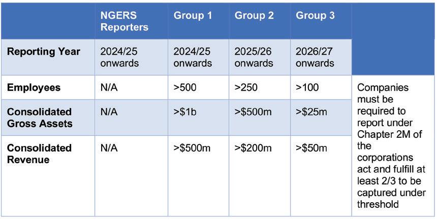
Risks relating to the potential negative effects of climate change are categorised as either physical risks or transition risks and opportunities relating to the potential positive effects arising from climate change include issues such as increased demand for related products
and services. The ASRS requirements will cover four main reporting components including:
• Governance
• Strategy
• Risk Management
• Metrics and Targets
The standards will be introduced under a phased approach, initially capturing Australia’s largest health care companies from 2024/25 then expanding to include all other (proposed) groups from 2027-28 reporting year onwards (see table below). Companies will be expected to disclose this information within their existing annual financial reports being provided to ASIC, usually required within four months after the end of the financial year in alignment with section 319 of the Corporations Act 2001.
challenges in achieving net zero in health care
There are significant challenges faced by the health care industry in achieving net zero. These include:
• Extremely high consumption of resources such as electricity, water and materials
• High waste output
• Infrastructure and technology issues
• Financial constraints
• Regulatory barriers
• Very large supply chains that contribute significant emissions, and
• Behavioural and cultural barriers.
Hospitals and similar facilities are highly energy-intensive due to their large size, continuous operation, and the significant energy demands of medical equipment and HVAC systems. Many of these buildings are very inefficient when it comes to energy usage. A government report (DCCEEW 2012) showed public hospitals consumed over half of public-sector energy
in most Australian states and territories in 2012 with this figure remaining similar in 2022.
Infrastructure and technology upgrades can be complex and costly. Many large-scale projects require thorough planning and co-ordination to minimise disruption to patient care. Planning for new technologies is also critical to guarantee interoperability between different systems and ensure staff awareness and training is adequate.
Introducing new data collection and reporting practices for net zero can introduce new challenges across the organisations. Availability and accuracy of data is the biggest issue when starting a reporting regime, followed by issues such as: availability of internal resources and systems, data privacy concerns and educating and training staff to deal with new complex issues.
opportunities to achieve net zero in health care
The first step is to prepare your carbon inventory; using available data, to estimate the carbon footprint of your organisation. There are several industry and government resources that provide templates and it wise to speak with industry professionals that can guide you through the process. This is the most crucial stage as it will identify your scopes and be the base line for future reporting. When developing you carbon inventory it is important to define whether it applies to Scope 1, 2 or 3 emissions.
Although 2050 is typically chosen as the target year for many net zero commitments it is important to set interim targets along the way to enable tracking of performance. Many organisations set intermediate targets around 2030, 2035 etc.
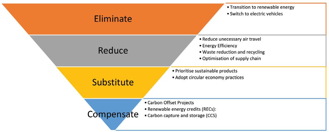

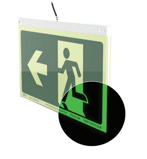




Step 3 – Determine reductions required to achieve targets
When planning your net zero journey, it is important to identify when each of the actions will be undertaken to achieve the target goals, this is very important as it will likely be dependent on available funds and resources to complete the projects. These need to be aligned with the target and target years outlined in Step 2.
Step 4 – Prepare and implement a net zero / decarbonisation strategy
It’s critical that health care organisations have a clear strategy around achieving net zero. The strategy should be aligned with the organisation’s long-term goals and corporate objectives and include clear achievable targets that are endorsed at the board level or equivalent. The net zero strategy should be able to summarise the goals and objectives of the organisation but also be detailed enough to identify emissions reduction opportunities that are ambitious, evidence-based and sufficiently detailed so they can be assessed for cost-effectiveness.
Step 5 – Identify opportunities for improvement
The health care sector should prioritise their GHG reduction activities in accordance with the carbon reduction hierarchy shown below. The elimination of GHG emissions should be prioritised first, followed by reduction (e.g. energy efficiency), then substitution (e.g. renewables, electrification), finally with compensation (e.g. offsets) used after all possible emissions reduction actions have been taken, to minimize eventual residual emissions.
Typical opportunities available to health care organisations include any of the following:
• Energy Efficiency
Building controls optimisation and re-commissioning
Sustainable building operations
Smart building control
HVAC upgrade
Lighting upgrade
• Solar (on-site electricity generation)
• Electrification
Electrification of services using natural gas such as domestic hot water, air conditioning heating & kitchens.
• Water efficiency
Reduce water consumption and wastewater
• Waste
Reduce waste & increase recycling rates. Several recent energy efficiency assessments undertaken by HFM highlighted specific issues for the health sector consider including:
• Using sub-metering to allow the wide range functional areas with these types of facilities to be monitored and analysed.
• The importance of configuring building controls to provide for the wide range of occupancy patterns within these facilities.
• The tendency for air conditioning, lighting and their control systems to be fragmented over time as refurbishments and additions occur without reference to a holistic approach leads to operational inefficiencies becoming embedded into business-as-usual operations.
• Rooftop solar power continues to offer excellent opportunities to offset grid energy emissions and costs.
• Insufficient planning for upgrade and replacement of aging plant and equipment increases the risk of replacement occurring under duress, resulting in like for like replacement and only incremental improvements in energy efficiency. The opportunity to take a holistic approach and delivering significant improvement is then missed for a substantial time.
The key to driving performance is accurate, near real time energy and emissions monitoring. Reporting aligned with emissions reporting frameworks such as the Carbon Disclosure Project (CDP) & Global Real Estate Sustainability Benchmark (GRESB), National Greenhouse & Energy Reporting (NGER), NABERS – Public Hospitals (Energy & Water) is critical. In recent years we have seen an increase in software and data analytics that assist in tracking this data. Some of the key data tracked includes:
• Net zero targets – emissions tracking and reporting
• Utility billing
• Stationary energy – liquid fuels
• Waste data
• Refrigerants
• Transport
• Supply chain
It is important that targets are stated, tracked and disclosed annually. Within the commercial property sector, it is now commonplace to see organisation stating their Environmental, Social, and Governance (ESG) performance.
By following a practical and methodical approach the health care sector can achieve significant decarbonisation in the future. With continued innovation and collaboration there is a positive outlook to achieving net zero within the sector.
1. Energy Savings Trust (EST). “What is net zero and how can we get there?”.2021. https://energysavingtrust.org.uk/what-is-net-zero-andhow-can-we-get-there/
2. Malik A, Lenzen M, McAlister S, et al. “The carbon footprint of Australian health care”. Lancet Planet Health 2018; 2: e27–e35.
3. Australian Sustainability Standards
4. Department of Climate Change and Energy Efficiency (DCCEEW). “Baseline energy consumption and greenhouse gas emissions – part 1”. Canberra: Commonwealth of Australia; 2012. Available from: https://www.energy.gov.au/sites/default/files/baseline-energyconsumption-part_1-report-2012.pdf

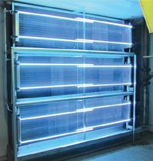
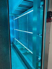




In our journey towards a sustainable future, innovation is enhancing electrical grids and power generation, making them more efficient and smarter, facilitating the integration of renewable energies. As electricity becomes greener, the transition to allelectric heating systems using heat pumps is key to achieving netzero emission targets.
Always focused on energy efficiency and environmental protection, MTA, further strengthens its commitment by adopting low GWP refrigerants such as Propane (R290) with a GWP of 3 and ODP of 0.
Coming soon, the iHCYGNUS N HP is MTA’s new airsource R290 heat pump with inverter compressor. Designed to reduce environmental impact, delivering high water temperatures with maximum efficiency and low noise operations makes this the ultimate sustainable solution. One unique unit for heating, cooling, and domestic hot water production.
For further details you can visit our website www.mtaau.com or contact us on 1300 304 177.
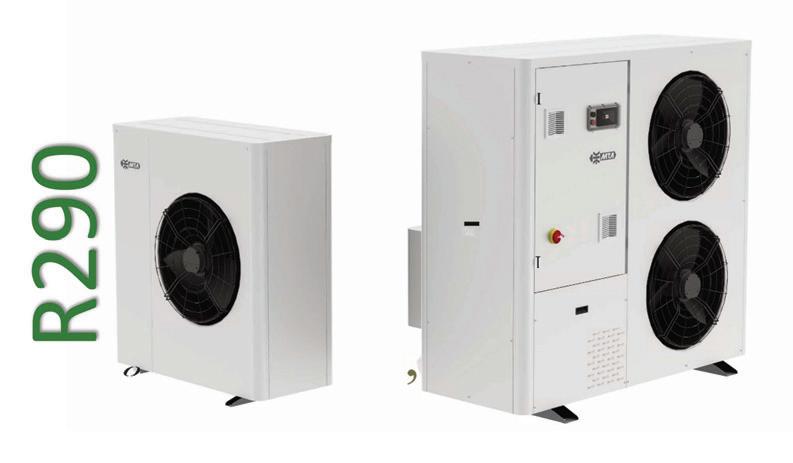


Control My Building is a trusted Building Automation System Integrator serving the Sydney region for over 8 years. We provide solutions for optimisation and control of Air Conditioning systems for commercial buildings, warehousing, retail, education and health care. We have extensive knowledge and experience in the supply, installation and commissioning of controls and monitoring of clean rooms, isolation rooms, PC2 labs, PC3 labs, theatres and other critical area.
We are trusted partners for Siemens, EasyIO and Distech Controls and working with our mechanical electrical team we can provide a turnkey solution for your needs. Our services include, but are not limited to, the following:
• Service and maintenance of the Siemens, EasyIO, Distech and Niagara products
• Supply, installation and commissioning of new BMS hardware including Siemens Desigo CC, EasyIO Niagara N4 and Distech Niagara N4
• Supply, installation and commissioning of variable speed drives
• Mechanical electrical works including supply and installation of mechanical services boards
• Preventative maintenance works of building automation equipment and VSD’s
Phone 0402 365 698 or visit www.controlmybuilding.com.au

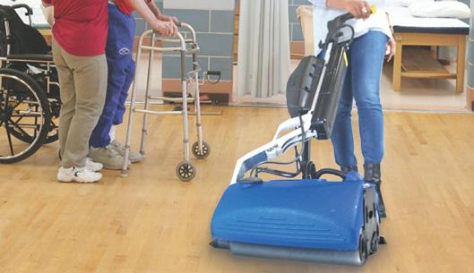
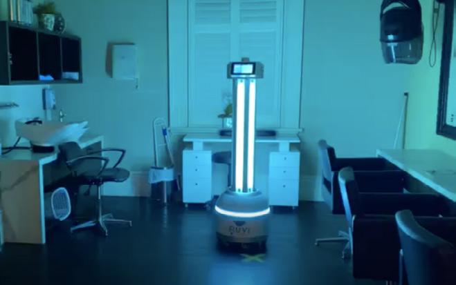






Gary Gilbert Business Development Manager Westco | Anixter
Local area networks (LANs) have historically been designed in a way that ensures all end devices are within 100 meters (m) of a telecommunications room (TRs) to comply with industry cabling standards. Now with the adoption of smart building technologies, more devices than ever are being connected to and powered via the network. Today’s LAN environments commonly encounter situations where a connected end device is located too far from the nearest TR to maintain the 100 m distance limitation.
While there are multiple standards-based options available to connect devices beyond 100 m, twisted-pair copper cabling is the preferred option due to less cost, material, and labor. However, there is confusion in the industry about the distances that twisted-pair copper cables can reliably support at various transmission speeds and remote powering levels. To strategically address scenarios where a device is located beyond 100 m with reduced risk, ICT professionals need to understand the pros and cons of the various options, technical factors involved, and key considerations surrounding testing to help them identify reality and navigate claims.
ANSI/TIA-568 cabling standards for commercial buildings define the minimum performance requirements for structured cabling to support a variety of applications (e.g., Ethernet, PoE, HDBase-T, DSL, etc.). These industry cabling standards are based on worst-case minimum performance of cabling system components, links, and channels to ensure an objective, realistic, and measurable basis for interoperability and competition in the marketplace. ANSI/TIA-568 cabling standards have long specified a 100 m distance limitation for horizontal twisted-pair copper cabling channels, which includes a 90 m permanent link with a total of 10 m of patch cable. Maintaining a fixed, universal horizontal channel length facilitates extrapolating performance parameters to support increasing transmission speeds. The 100 m distance limitation specified in industry cabling standards has therefore been carried over through generations of twisted-pair copper
cables, from Category 3 capable of supporting 10 Megabits per second (Mb/s) to Category 6A capable of supporting 10 Gigabits per second (Gb/s).
With emerging IoT and smart building initiatives, more devices in more spaces than ever need to connect to the network. To cover outdoor spaces, warehouses, parking garages, and other remote areas, it is extremely common for an enterprise facility or campus to require a surveillance camera, access control device, wireless access point, or other device in a location beyond 100 m from the nearest TR. To reduce cost and improve efficiency, many of these devices are also now digitally powered via remote powering technology like power over Ethernet (PoE) rather than connected to a traditional AC power circuit. Cabling standards-compliant options for connecting and powering devices beyond 100 m include adding a new TR, using a decentralized extender device, connecting the device with fiber optic cable and separately delivering power, or using a hybrid copperfiber optic cable to deliver data and power. Each of these standards-based options has its pros and cons.
One option for connecting devices beyond 100 m is to add another TR. This could be an actual room, or a mini TR housed within in a freestanding or wall-mounted cabinet. The benefits of adding another TR include compliance with industry cabling standards, centralized management, and the ability to support speeds up to 10 Gb/s and deliver up to 90 W of PoE. However, the cost of adding a new TR is virtually impossible to justify if only needed to support a few remote devices located beyond 100 m. Not only do TRs take up valuable real estate, but they require additional active equipment and associated power consumption, cooling, and maintenance.
Deploying an Ethernet extender device within the horizontal cable plant is another option for supporting remote devices.
Far less expensive than adding a TR, extender devices leverage existing twisted-pair copper cabling, and depending on the device, can support up to 10 Gb/s and up to 90 W of PoE. However, extender devices typically require local power, which adds expense. Locating an extender device out in the horizontal space also adds a remote point of failure and eliminates centralized management, which can make troubleshooting and maintenance more difficult, disruptive, and costly.
Another option for extending distance to devices in the LAN is to connect the device via fiber optic cabling. Per TIA standards, an OM3 or OM4 multimode fiber link can support speeds of 10 Gb/s to a distance of about 300 m or 1000 Mb/s to a distance of about 550 meters. While fiber is an ideal solution for these longer distances, the cost of fiber transmission equipment is difficult to justify for a few LAN devices located just 10 or 20 meters too far from a TR. Furthermore, end devices with a fiber input/output (I/O) port are limited in the marketplace. A media converter and copper patch cord is therefore often required to make the device connection. PoE media converters offer the benefit of delivering PoE power to the device but using fiber optic cabling with media conversion still requires the higher cost of fiber transmission equipment. Like an extender device, PoE media converters are also a remote point of failure that require power.
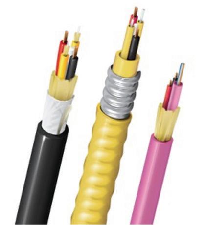
power source. Once deployed, if the conductor size is too small or the distance is too far to support the power requirements of the end device, the only options are to replace the cable, add additional copper conductors, or reduce the link length. This can significantly hinder moves, adds, and changes, as well as the ability to leverage the hybrid copper-fiber cable for future devices.
While not compliant with ANSI/TIA-568 cabling standards, the most costeffective option for connecting devices located beyond 100 m is to simply extend the distance of a twisted-pair copper cabling link. This approach requires no extra space, equipment, or points of failure.
Twisted-pair copper cables also support familiar modular RJ45 connectivity and installation practices—other than pulling the cable farther than 90 meters from the TR, the installation process for a longer link is no different than any other twistedpair copper cabling link. Using twisted-pair copper cabling also supports centralized management, facilitates troubleshooting and maintenance, and supports efficient remote power delivery via PoE directly from a PoE-enabled switch.
When comparing the various option for connecting a device located beyond 100 m from the closest TR, it’s clear to see that twisted-pair copper cable is the most appealing from a cost standpoint when the cost of design, material, power, labor, and maintenance are taken into account as shown in Figure 2.
Even if a device does include a fiber port for connecting it directly to the fiber network and does not require a media converter, the device will need to get power through some other means than PoE if local power is not available. One option is to use a hybrid copper-fiber cable that includes fiber for the data transmission and copper conductors for power delivery. The use of hybrid copper-fiber cable still requires more expensive fiber transmission equipment, as well as a Class 2 limited power source (LPS) to deliver the power. Note that Class 2 power delivered over hybrid copper-fiber cable is not PoE. While PoE is a type of Class 2 power, it is only supported by twisted-pair copper cabling.
When using hybrid copper-fiber cable, it is important to carefully select the size of the copper conductors, which typically ranges from 12 to 20 AWG. The gauge of the copper directly impacts how much power can be delivered over certain lengths. In addition, using Class 2 non-PoE power over hybrid copper-fiber cable requires careful planning and voltage drop calculations to ensure enough power to support a device based on its current draw and distance from the

While twisted-pair copper cabling is the most cost-effective and preferred choice for extending horizontal cabling distances beyond 100 m, there are several considerations. Because extending the distance of a twisted-pair copper cabling channel beyond 100 m is not compliant with ANSI/TIA-568 cabling standards, it is necessary to look at application standards instead.
Cabling standards define the minimum performance requirements for structured cabling links, channels, and components to support an application usually to 100 m with
the goal of ensuring interoperability between components from different manufacturers. Certification testing to cabling standards is performed at the time of installation, as often required by scope of work and to acquire warranty. Testing to cabling standards is conducted on cables that are not yet actively supporting an application, connected to a device, or transmitting data. Theoretically, cables that comply with cabling standards should ensure support for any application designed to be used with that specific type of cable to 100 m. In contrast, application standards look at the ability of specific applications to run on a link segment, regardless of the cabling components and the distance.
Length-dependent performance parameters like insertion loss, propagation delay, DC resistance, and signal-to-noise ratio (SNR) are closely tied to the ability of a link segment to support a specific application to a specific length.
• Insertion Loss—Measured in decibels (dB), insertion loss is the amount of energy that a signal loses as it travels down the cable. If the loss is too high, the signal may not be strong enough to be properly received or interpreted by the connected active equipment. The greater the distance a signal has to travel, the greater the insertion loss. Connection points within a link add to the overall insertion loss. Insertion loss also increases with frequency and temperature. That is why the maximum allowed insertion loss per cabling standards is higher for Category 6A specified to 500 MHz (42.8 dB) versus Category 6 at 250 MHz (31.1 dB), Category 5e at 100 MHz (21.0 dB), and so on. It is also why industry cabling standards specify a maximum ambient operating temperature of 20°C (68°F) for twisted-pair copper cabling and recommend reducing (de-rating) channel length for higher temperatures.
• Propagation Delay—In four-pair applications, propagation delay (i.e., the amount of time it takes for a signal to be received at the far end of a link), increases with length and can vary from one pair to another. Measured in nanoseconds (ns), if the difference between the pair with the least delay and the pair with the most delay is too high, it can cause bit errors that prevent proper data transmission. In video surveillance applications, too much propagation delay is often observed as a jittery picture.
• DC Resistance—DC resistance is a measurement of a conductor’s ability to resist the flow of electrical current. Measured in ohms (Ω), DC loop resistance is the DC resistance of two conductors in a pair looped (connected) at one end of the link. For PoE applications, DC loop resistance defines the ability to efficiently deliver power. According to IEEE PoE application standards, the channel DC loop resistance of a pair shall be 25 Ω or less. Exceeding DC loop resistance limitations has an adverse effect in the ability of a PoE system to deliver power and generates heat within twisted-pair copper cables, which
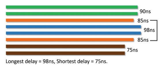
in turn increases insertion loss. For twisted-pair copper cable pairs carrying data in conjunction with PoE power, DC resistance of each conductor within the pair needs to be essentially equal. The difference in DC resistance between two conductors is referred to as DC unbalance. If the DC unbalance is too high, it can cause data signals to become distorted, causing bit errors that prevent proper data transmission.
• Signal-to-Noise Ratio (SNR)— SNR is a relative measure of the signal power compared to the noise power over a specific frequency range. Measured in dB (like insertion loss), the higher the ratio between the signal and the noise, the better the signal quality. SNR is directly related to insertion loss—lower insertion loss improves SNR, and because insertion loss increases with distance, SNR is therefore also impacted by the length of the cabling link. Too low of an SNR reduces the transmission speed supported or requires link length to be reduced.
Key Influencing Factors
Insertion loss, DC resistance, propagation delay skew, and SNR that affect the distance a twisted-pair copper cable can support for a given application are impacted by several influencing factors—from speed and PoE level, to cable construction and quality and a variety of design and installation variables. All of these factors are why there are currently no industry cabling standards for extending the distance of twisted-pair copper cables beyond 100 m.
• Transmission speed and level of PoE power—Faster transmission speeds operate at higher frequencies, which increases insertion loss. The amount of PoE power available at the end device also decreases with distance due to voltage drop. Therefore, the faster the speed and the higher the power, the less the distance that can be supported over twisted-pair copper cabling.
• Cable and patch cord construction—Insertion loss and DC resistance are largely dependent on the gauge of the conductors that comprise twisted-pair copper cables. The larger the gauge, the less the insertion loss and resistance. Additionally, stranded conductors, such as those used in patch cords, exhibit higher insertion loss than solid copper conductors. Shielding and even the dielectric material used in the cable’s insulation and jacket material can also impact insertion loss and DC resistance.
• Cable and patch cord quality—Inconsistent pair geometry and twist rates and variations in diameter, concentricity, contour, and smoothness of the copper conductors can cause DC resistance unbalance and propagation delay skew that impact distance capabilities. DC resistance is also a concern in low-quality and often counterfeit copper clad aluminum cables and patch cords. Aluminum exhibits more than 66% higher DC resistance than copper, which can easily exceed the 25 Ω limitation for PoE applications and also generate too much heat. Accordingly, copper clad aluminum cables are not compliant with industry cabling standards and do not meet UL safety listings per the NEC (Click HERE to learn more).
• Network topology—How devices are connected to the network (i.e., directly with modular plug-terminated links or via outlets and patch cords), and the total number of connectors in the channel impact insertion loss and distance capability. The more connections in the channel, the greater the insertion loss.
• Heat Rise and Temperature—The amount of heat generated by the flow of DC current in PoE applications, the overall ambient temperature, and the ability of the cable to dissipate heat can all create heat rise in twistedpair copper cabling. This increased heat increases insertion loss. Within bundles of cables carrying higher levels of PoE power, it is more difficult for heat to dissipate. Industry standards and the National Electrical Code (NEC®) address heat rise in cable bundles carrying DC current by limiting bundle size. For 100 m twisted-pair copper cabling channel lengths, industry cabling standards are specified at an ambient operating temperature of 20°C (68°F) and recommend reducing (derating) channel length for higher temperatures.
• Poor Workmanship—Improper installation practices such as exceeding cable bend radius, compressing or kinking cable, not consistently terminating all conductors, or not properly maintaining pair twist right up to the termination point can increase DC resistance unbalance and propagation delay skew that limit distance capabilities.
There are several IP-based network devices that operate at lower speeds of 1000 Mb/s or less and require lower levels of PoE power. Devices such as surveillance cameras, call boxes, access control panels, PoE lighting fixtures, time clock systems, intercom/paging systems, energy management systems, and environmental sensors and controls are examples of lowerspeed, lower-power devices that often need to be located beyond 100 m. For example, there may be the need to locate a surveillance camera out in the warehouse, an access control panel at the far end of factory, or an emergency call box in the parking garage. At lower speeds and lower levels of PoE power, performance factors such as insertion loss and voltage drop are less likely to impact distance capabilities.
In addition, most reputable manufacturers design quality twisted-pair copper cabling systems that exceed cabling standards and offer more headroom, including improved insertion loss, propagation delay, and DC resistance. While this helps ensure support for applications to 100 m regardless of installation variables and environmental factors, it has also allowed several reputable manufacturers to qualify certain twisted-pair copper cables to support a variety of low-speed, low-power applications to distances beyond 100 m. Many of these advanced cables are even promoted as offering extended distances for specific applications. In contrast, minimally compliant cables with no headroom are far less likely to support extended distances. In fact, minimally compliant cables are more prone to marginally pass or even fail at 100 m distances due to installation variables and environmental factors.
Unfortunately, there is much confusion in the industry about the distances that twisted-pair copper cables can reliably support at various transmission speeds and remote powering levels. Much of this confusion stems from some manufacturers claiming the ability to support extended distances for high-speed, high power applications based on inadequate approaches to testing and verifying performance at various lengths. The reality is that supporting transmission speeds of 10 Gb/s and higher level Type 3 (60 W) and Type 4 (90 W) PoE to extended distances is extremely challenging – even for reputable, innovative manufacturers. Applications that require these higher speeds and PoE levels, such as the emerging high-throughput Wi-Fi 6/6E deployments, are therefore not feasible over twisted-pair copper cable links that reach much beyond 100 m.
When considering the use of twisted-pair copper cabling to extend distances beyond 100 m, it’s important to carefully navigate the claims by verifying manufacturers’ technical specifications for their cables, understanding testing requirements, recognizing risks, and asking the right questions.
When selecting twisted-pair copper cables for distances beyond 100 m, it’s important to review manufacturer specifications and understand how the cables have been tested. Reputable manufacturers test their cabling systems to comply with the minimum performance requirements of cabling component standards. This ensures support for any application designed to run on that specific cable type (i.e., Category 5e, Category 6, Category 6A, etc.) to 100 m. Installers then field test the cable plant to cabling standards to ensure that installed links also meet the performance and distance requirements to support applications designed to run on the specific cable. However, compliance with cabling standards does not indicate whether the cables will support
applications beyond 100 m. This is where application testing comes in. As previously discussed, application standards look at the ability of specific applications to run on a link segment, regardless of the cabling components and the distance, and considers parameters such as insertion loss, propagation delay, DC resistance, and SNR.
Reputable cabling manufacturers conduct rigorous lab testing and third-party verification of distances based on IEEE application standards (i.e., Ethernet, PoE, etc.) and various conditions such as topology, ambient temperature, and end device requirements. They also conduct laboratory bit error rate (BER) testing using specific device network interface cards (NICs). BER testing sends actual Ethernet data packets at a specific speed in both directions to check for errors. It is through this comprehensive testing approach that many reputable manufacturers are able to warrant twisted-pair copper cables for specific applications and distances beyond 100 m.
Application testing can also be conducted in the field and is recommended for twisted-pair copper cables in channel lengths greater than 100 m. Application testing reduces risk by ensuring support for an application over a specific distance. BER testing can also be done in the field but unlike application testing, it evaluates a specific device over a specific distance and under specific conditions. In other words, BER testing is geared more for evaluating an engineered solution and can fail if any variables change, including the device, temperature, external noise, and other factors. Figure 4 shows the difference between cabling standards, application standards, and BER testing.
For anyone considering twisted-pair copper cabling to connect a device beyond 100 m, it’s important to understand that every device is unique. Equipment manufacturers design switch ports and devices to meet minimum requirements for successful transmission within application link segment limits, which is easily achieved with 100 m of cabling. However, performance can vary in each device’s ability to accommodate transmission irregularities associated with extended distances. That means that an extended distance link that successfully connects two specific devices may not function if one of the devices is changed. This is true even if using the same vendors’ equipment, but a different type of device.
The variability that occurs in extended-distance links introduces uncertainty, which is why application testing is so important—both in the lab via the cable manufacturer and in the field. If only BER testing was performed, swapping out devices and changing the conditions cannot guarantee performance, which eliminates the ability to future proof.
Given the wide range of variables that impact distance capabilities and various marketing claims in the industry, it’s important to ask the right questions when selecting twisted-

pair copper cables for extended-distance deployments. This is especially the case for vendors claiming that their cables can support higher transmission speeds and PoE levels to distances that appear too good to be true and/or are far beyond the specifications of trusted, reputable manufacturers. Adhering the following guidelines can significantly reduce risk:
1. Ask your cabling manufacturer what type of testing was conducted to determine the advertised distance capabilities for a specific application speed and level of PoE. Buyer beware if rigorous laboratory-based application testing and BER testing were not conducted. If only BER testing was conducted, understand that changing the device or a single variable may prevent the link from functioning. Make sure to also ask for any testing documentation as proof.
2. Find out if the cable is covered by warranty and for what distance, application, and PoE level, and what type of field testing is recommended and/or required to maintain that warranty. While most reputable manufacturers will a uphold warranty as long as the permanent link test passes for all application standardsbased parameters except for length, it is recommended to always check on specific warranty requirements for extended-distance deployments.
3. Request that the cabling manufacturers simulate your specific environment, equipment, and configuration to ensure it will function prior to installation. This is especially important for cabling manufacturers that can not produce adequate application testing results and/or do not
offer a warranty. If there is any uncertainty in the ability of a manufacturer’s cable to support an application and deliver the required level of PoE to a certain distance, it is better to look elsewhere or choose a standards-based solution for extending distance.
It wasn’t long ago that we saw cabling standards established, and now the industry simply wouldn’t operate without them. While industry standards do not currently address extendeddistance deployments due to all the variables, there is light at the end of the tunnel—we are seeing movement in creating extended distance standards, which will help eliminate confusion in the marketplace and prevent manufacturers from making marketing claims without the testing to back it up. Collaborative effort between several cable manufacturers, standards bodies, and distributors are already helping to establish verified methods of measurement that guarantee results and protect design intent for extended reach, standards-based installations. New single-pair Ethernet (SPE) standards that support low-speed 10 Mb/s devices to 1000 meters and PoE up to 13.6 W may also eventually address the need for greater distances in connecting sensors, actuators,

relays, and controllers used in building automation systems and some security deployments. For this to come fruition, equipment vendors will need to integrate SPE technology into their chipsets.
In the meantime, anyone looking to extend the distance of twisted-pair copper cabling beyond 100 m should talk to their cabling manufacturer and ask the right questions to verify performance before investing. If marketing claims are seemingly farfetched, look to reputable cable manufacturers that stand by empirical evidence and warranty their cables for applications and power levels to realistic distances. Consider that twisted-pair copper cables from even the most reputable and innovative manufacturers cannot typically support speeds of 1000 Mb/s or higher at the highest 90W Type 4 PoE much beyond 100 m due to physics. For lower-speed 100 Mb/s applications, which includes many types of devices, distances may reach significantly above 100 m, especially at lower levels of PoE. For many low-speed devices, using twistedpair copper cables from reputable manufacturers to extend distances beyond 100 m is risk free and highly cost effective. But at the end of the day, anyone looking to select twistedpair copper cabling systems for distances beyond 100 m should do their due diligence.

PPE Stations & Dispensers are the ultimate IPC solution with 100's of versatile combinations to enhance your infection control programs


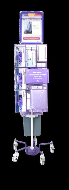
Quality products for funeral homes and mortuaries, designed and customised for the final journey.


500kg Mortuary Trolley
Electric over Hydraulic system, drive unit, Auto tray loading, electric body tray brake
500kg Ceiling Hoist
2 speed, 270º swivel, adjustable length straps ergonomic pendant, head strap, ceiling track system

Body trays and coffins, guide rails. Options: Front/ side loading, 3/4 Tier, fixed or mobile

Enhancing Patient Safety & Asset Reliability: How


CETEC, is a leading Australian consultancy with over 35 years of experience in Air and Water risk management. With a systems-based approach CETEC delivers bespoke solutions incorporating testing, reporting, gap analysis and project management. Backed by a NATA accreditation it is supported by local consultants in our many offices nationwide. Our water expertise focuses on risk management solutions for AS 5369 compliance, control of waterborne microbes such as legionella, and corrosion management to ensure safe water for every application.
CETEC has encountered water-related risks in both modern and older healthcare facilities. These risks span chemical species (organic and inorganic), biological, and other physical attributes. Most can be mitigated or eliminated through wellconsidered, often bespoke, design strategies.
Our process begins with evaluating the water source. Water risks vary significantly depending on the source and application. There is no universal water quality standard that fits all purposes; so, healthcare requirements often require on-site water treatment to ensure suitability. The services delivered in the facility also influence the risk profile of the water delivered to users and applications.
Good design entails a thorough understanding of the supplied water, considering Australia’s diverse sources— dams, rivers, desalination plants, groundwater, and rainwater. Variables such as disinfectant type, concentration, and efficacy must also be considered.
The reliability of water supply should be integrated into the design process. Factors such as excessive storage time and water temperature can impact disinfectant levels upon reaching the facility.
Water quality is a balance. For instance, excessively soft water can leach metals from components, while hard water may cause scaling and blockages in hydraulic systems. CETEC emphasizes factoring water chemistry and microbiology into the early design stages. Physical factors like turbidity can affect UV sterilization efficacy and sedimentation in pipes, which pose biofilm colonization risks. Installing a
purpose-designed water treatment plant can provide storage, adjust water quality, and maintain appropriate disinfectant levels.
CETEC has managed numerous projects incorporating bespoke water treatment systems, significantly improving hydraulic system management from microbiological, contaminant, and corrosion perspectives.
Microbiological control is predominantly achieved by maintaining proper disinfectant levels in cold water and adequate temperatures in heated water systems. Effective cold-water systems should ensure uniform disinfectant distribution, with strategies such as regular flushing of unused outlets. However, potential limitations of the flushing strategy include:
• Inadequate flow velocity in oversized or lengthy pipes which retain large volumes of stagnant water.
• Dead legs harbouring stagnant water and a reservoir of microbes
• High cold-water temperatures causing disinfectant loss, and microbial colonisation
• Low flow or stagnation in ring mains that are fed from both ends with no circulation
• Shared systems with stagnant lines
• Inadequate flushing plan for the outlets
• Low incoming disinfectant levels, or processes that remove the disinfectant
In systems with poorly distributed disinfectant, CETEC often recommends recirculating water from distal network points back to the process start, supplemented with additional dosing if necessary. New builds should incorporate these systems, minimizing spur line lengths and appropriately sizing piping. Removed lines should be terminated at the junction on the main.
Hot water systems should recirculate to the storage, maintaining 60°C to 70°C, with returns above 55°C, per AS 3500.4 standards. CETEC advises higher return temperatures to ensure pasteurization whenever the attached outlet is used. Maintaining high temperatures curtails microbial colonization risk.
Warm water systems are necessary to prevent scalding, but piping length should be minimal between the TMV and outlet. Having a high hot water temperature ensures that a

larger amount of disinfectant laden cold water is used in the TMV to lower the temperature resulting in some disinfectant protection of the warm water line. Some facilities have been designed with warm water circuits, which may not conform to enHealth Legionella Guidelines and AS 3500.4 standards, posing a significant Legionella colonization risk. Also, a single TMV servicing multiple outlets is discouraged due to the length of the warm water lines required and the resulting biofilm colonization risks.
CETEC’s bespoke approach typically involves a review of incoming water quality recommending appropriate treatment and storage systems, followed by a comprehensive review of water circuits. This typically involves returning a smaller water stream to maintain disinfectant flow throughout the facility. The return point and volume are optimized to sustain required disinfectant concentrations. Flushing of infrequently used outlets remains necessary but minimized.
Hot water circuits are generally designed to recirculate but must maintain the required return temperatures, ensured by
functional circulating pumps and adequate insulation. Short warm water lines are optimal.
Local treatment plants are usually installed to provide water of the appropriate quality in the sterilising department. These include the use of reverse osmosis plants (RO) with or without deionization to remove inorganic ions and endotoxin from the incoming potable water. However maintaining this water free of microbial growth and endotoxin level requires careful selection of plant with appropriate hydraulic design and cleaning regimes specific to the materials used in the plant.
Solutions for the water supplied for initial cleaning of surgical equipment have included dilution with RO water, however the effect of a more corrosive RO treated water should be considered.
The rinse water for reprocessing thermolabile endoscopes requires a bespoke approach as the requirement for TVC (total viable count) and the endotoxin parameter can be difficult to meet.
Water for Renal plants must be available at the quantity required, at all times that the facility is operating.
Corrosion risks in hydraulic systems arise if materials are unsuitable for the quality of water used. Water chemistry expertise is invaluable for system design and remediation. Material selection based on past use or cost is inadequate due to varied water sources, dissolved material content, microbiological risks, and potential disinfectant levels. Watermarked products do not guarantee corrosion resistance or non-susceptibility to leaching. Scaling indices will not predict all possible corrosion risks.
Purpose-designed water treatment plants with appropriate distribution strategies offer flexibility to adjust water properties, mitigating microbial, chemical and other corrosion risks and promoting extended operational life of the system.
Appropriate water quality and effective risk management involves a careful integration and prioritisation of many diverse elements. At CETEC, we adopt a system-based approach that not only aids in efficient facility design but also optimizes retrofits to significantly reduce water risks. Our bespoke solutions are tailored to address key aspects of microbiological control, system reliability, and corrosion prevention. With the backing of NATA accreditation and local offices, we guarantee unparalleled water safety and quality in healthcare environments, offering peace of mind through our strategies proven in many of our clients’ facilities.

There is a growing demand for products that can create comfortable indoor spaces while maintaining a healthy and productive working environment. At the same time, new government policies and the dramatic increase in energy costs have created a greater need for products and systems that utilise energy-efficient technologies.
Our next generation of Rickard VAV Diffusers provides occupants with optimised thermal comfort and are easier to install. These diffusers can operate through a BMS or Rickard standalone software, and reduce power consumption by lowering demand on the air handling system. The system can accommodate a single Rickard VAV diffuser or can be expanded to control thousands of networked VAV diffusers. Each Rickard diffuser is self-modulating, allowing for easy control of smaller zones and making them more comfortable for occupants. Combined with smart commissioning software, this VAV design enables substantial benefits.
Fantech Product Manager for Intelligent Ventilation Systems, Peter Henry, said the next generation of Rickard VAV diffusers has been redesigned for easier installation. “The new design simplifies commissioning, as each Rickard diffuser automatically zones when it is first powered,” he said. “ Additionally, all diffusers are now configured as masters, as it is generally preferable to monitor the temperature where each diffuser is installed. If any diffusers do need to be assigned as slaves, they can be easily changed using the Rickard MLM software.”
Rickard diffusers only allow the required amount of conditioned air to enter the space, determined by the temperature in the space and the set-point on the diffuser’s integrated sensors and wall thermostat when installed.
The set point on individual diffusers can be easily adjusted for personalised comfort control over the environment during any part of the day.
“These re-engineered diffusers help with commissioning on several levels,” explained Peter. “They are designed to be more reliable, with an all-powder coated metal construction, and the complexity of parts on the diffuser has been significantly reduced to streamline installation.”
A key benefit of Rickard VAV diffusers is their ability to reduce the demand on the fan system by providing only the required volume of hot or cold air to enter the conditioned space. If the air volume required reduces, the diffuser’s aperture size also reduces which creates additional pressure in the ductwork. This pressure signals to the air conditioning system to slow down, which in turn saves fan energy. If the air volume required increases, the diffuser’s aperture opens, allowing more conditioned air to enter the space.
Standard features now include a temperature sensor at the neck of every ceiling diffuser to monitor temperature at the outlet point before supply air enters the space. Plus, an onboard thermostat beneath the diffuser faceplate to accurately monitor the temperature within the space. This ensures consistent and customisable climate control for optimised thermal comfort in the building.
Peter added, “Occupancy sensors has also been made standard on every Rickard diffuser. When a room with occupancy sensing is vacant, the Rickard diffuser will automatically reduce the supply of air to that room, which can further reduce energy costs.”
For further information on the next generation of electronic Rickards VAV diffusers, contact Fantech on 1800 133 379.
Centigrade Medical Gases Pty Ltd specialises in Medical Gas and Laboratory gas Installation, break down repair, maintenance, and commissioning services. Our dedicated team of seven includes a manager, supervisor, four technicians, one apprentices, and administrative support. We play a vital role in ensuring the functionality and efficiency of Medical Gases systems, particularly in
industries like healthcare, university and pharmaceuticals that rely on controlled environments.
Our mission is to be leading the charge in healthcare innovation, focusing on the critical role of medical gas and laboratory systems. We’re committed to delivering tailored, high-quality solutions that support patient care and enhance medical procedures.
Visit www.centigrade.com.au or www.centigrade.com.au/medical-industrial-gases/
KAESER compressors and the compressed air they generate are used in a multitude of applications. However, the fact that compressor exhaust heat can be harnessed often remains forgotten. This opportunity saves energy and costs, while also reducing the CO² footprint.
100% of the drive energy supplied to a compressor is converted into heat. This heat could simply be conveyed away, however, there are plenty of ways to make use of this readily available energy source.
The simplest, most efficient method is to use the compressor heat directly. That is, air ducting directs the heat to neighbouring rooms or buildings.
In addition to providing space heating, hot compressor air can be used for applications such as drying processes, generating hot air curtains or preheating burner air for heating systems. Compressor
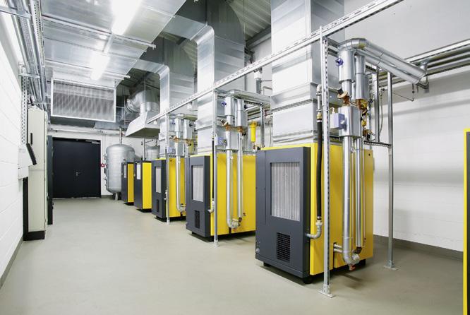
exhaust heat can also be used to supply hot water heating and service water systems.
For more information about KAESER heat recovery : https://au.kaeser.com/products/rotary-screw-compressors/heatrecovery/
Neo-natal wards? Oncology wards? Burns units? These patients suffer high consequences for respiratory infections, yet HEPA filtration standards are not generally applied.
Why? Because conventional HEPA filters lead to massive increases in costs, energy and emissions.
But that’s a problem that has now been solved. PlasmaShield provides HEPA standard decontamination - plus deodorisation and disinfection – yet avoids the increase in costs, energy and emissions.

Your engineering team can learn more at https://plasmashield.com.au/


Established in 2006, Building Services Recruitment Australia (BSRA) has extensive experience recruiting for hospitals and across the healthcare industry.
Specialising across Facilities Management hard services, we recruit Project Directors, Construction & Engineering Managers, Project Managers, Project & Technical Engineers, Contract Managers & Administrators, Commissioning Managers, Asset Managers & Reliability Engineers, Energy Engineers, Quantity Surveyors, Essential Services Managers, Auditors and Facilities Management Specialists.
We offer both permanent placement and short-term labour hire solutions servicing commercial and government clients at federal, state, and local levels.
Visit the Building Services Recruitment Australia Website at https://www.bsra.com.au/
Having a clean and hygienic environment for residents and patients is paramount for a successful Healthcare business. You can clean all you like, but it can be difficult to get rid of those bad smells coming from the bathroom floor drain and the last thing you want is the smell being what is remembered about your Healthcare facilities.
Using harsh and nasty chemicals is a short term and costly solution. The simple, easy, cost effective and environmentally friendly solution is Drain Mate® How it works
Drain Mate® is a one way floor drain that fits easily into your existing standard 100 mm (4 inches) floor drain. Drain Mate’s unique self-closing trap door lets waste and water through, but keeps smells, pests, noise and overflow out.
Design and manufacture
Designed, invented, and made in Australia, Drain Mate® is made from quality ABS plastic, and is 100% recyclable. Drain Mate® has also been subjected to testing by a recognised testing laboratory for Australian Standards and has been granted Level 2 Certification and complies with approved specifications WMTS-040:2022 (License: 023117). Drain Mate® is easily installed; no plumber required and attaches to your existing floor drain grate cover using one of our four supplied washers and attachment screw. There is also no need for any additives for Drain Mate® to function correctly and is easily removed for cleaning.
Where it is used
Drain Mate® has been installed in many, many bathrooms throughout Australia, both residential and commercial, providing an immediate solution for drain smells and pests.

Drain Mate® can be installed anywhere there is a 100 mm floor drain, including homes, apartments, hotels and motels, restaurants, hospitals and healthcare facilities and schools.
More information
For further information on Drain Mate®, visit our website www.aussiedrainmate.com.au for a demonstration video, installation slide show, where and how to buy Drain Mate® There is also an FAQ section on the website that can answer your questions about the manufacture Drain Mate®; fitting, operation, and maintenance of Drain Mate® .
You can also simply contact Mark on 0400 193 821 to discuss how Drain Mate® can solve your 100 mm floor drain problems.

