
1 Project
–
ENGINEERING
TECHNOLOGY
THESIS
USE DEVELOPMENT Z
BY MR.
CHANDRASHEKHAR PATIL
THESIS GUIDE PRINCIPAL DEAN PROF. PRIYANKA CHOUGULE DR.SANTOSH CHEDE PROF. R. G. SAWANT HEAD OF DEPARTMENT PROF.
JADHAV
1
Thesis Synopsis D.Y.PATIL COLLEGE OF
AND
SHIVAJI UNIVERSITY KOLHAPUR
MIXED
SUBMITTED
ADITYA
FINAL YEAR.PART II
I. S.
D.Y.PATIL COLLEGE OF ENGG & TECH DEPARTMENT OF ARCHTTECTURE SHIVAJI UNIVERSITY KOLHAPUR CERTIFICATE
This is to certify that Mr. Aditya Chandrashekhar Patil has duly submitted the project Report with drawings entitled
MIXED USE DEVELOPMENT AT MUMBAI
In the Department of Architecture in partial fulfilment of the requirement of The Bachelor of Architecture Degree course of Shivaji University, Kolhapur 2019 2020 and is a benefited work of the student and has been completed The same under the supervision and guidance of Prof. Priyanka Chougule
Date: 27th September 2020
Place: KOLHAPUR
THESIS GUIDE PRINCIPAL DEAN
PROF. PRIYANKA CHOUGULE DR.SANTOSH CHEDE PROF. R. G. SAWANT
HEAD OF DEPARTMENT PROF. I. S. JADHAV
Project 1 – Thesis Synopsis
2
ACKNOWLEDGEMENT
As I come to the completion of my thesis, I realize that a lot of it would not have been possible without the help, support and encouragement given to me, by those, to whom I feel greatly indebted to.
Today, as I submit my thesis report on the topic “MIXED USE DEVELOPMENT, MUMBAI”, I take this opportunity to express my heartfelt gratitude to all those who were behind me in the completion of my thesis.
I convey my sincere gratitude to my guide, and teacher, Prof. Priyanka Chougule, Department of Architecture, for her constant support, guidance and understanding throughout my thesis.
I am thankful to Prof. R.G. Sawant, Dean of the Department of Architecture and Prof. I. S. Jadhav, Head of the Department of Architecture for having inspired me through her kindness and knowledge.
I am grateful to all the teachers and the non teaching staff for availing me all the facilities for successfully accomplishing this thesis and helping me during all the stages of my work.
I also thank my friends and classmates, who have always been there to support me.
I would like to thank my parents, and my entire family, for always being there to encourage me to move forward, with their love, support and prayers.
MR. Aditya Chandrashekhar Patil
3 Project
1 – Thesis Synopsis
INDEX
4
Project 1 – Thesis Synopsis
Sr. No. Chapters Page No. 1. SYNOPSIS INTRODUCTION AIM NEED OBJECTIVES SCOPE LIMITATIONS 5 2. LITERATURE STUDY 12 3. CASE STUDIES BLUE RIDGE LINKED HYBRID SONY CENTER INFOSYS HYDERABAD CAPITAL BUILDING 36 4. SITE ANALYSIS 89 5. DESIGN DEVELOPMENT 105 6. DRAWINGS 113
CHAPTER I
SYNOPSIS
Mixed Use development at Mumbai
5 Project 1 – Thesis Synopsis
MIXED USE DEVELOPMENT AT MUMBAI Introduction
Mixed Use Development
The Sustainable Urbanism typology is based on the principle of multi functionality. The term Multifunctionality denotes the ability of a large system to perform many functions. In this thesis, functions are urban services which are different types of activities in urban area (housing, industry, health care, trade, education, etc.). This thesis aims to study Multifunctionality as a phenomenon of urban environment.
Mixed use development is the practice of allowing more than one type of use in a building or set of buildings. In planning terms, this can mean some combination of residential, commercial, industrial, office, institutional or other land uses. This tends to create shorter distance between work, residence and recreation and goes a long way to enhance the livelihood of the inhabitants.
Functions, mixed use buildings can perform, include : office, residential, serviced apartments, hotel, retail, exhibition, casino, etc. According to the degree of their development, these functions can be divided into 3 main types: dominating, additional and accompanying.
The true environment forming role can be seen only when you thoroughly analyses how these large scale buildings have been integrated into the urban environment, especially at the level of its connection to pedestrian and traffic flows. It is very important that the building, which includes many functions and services, does not become an unassailable fortress where housing is available only for the tenants, offices for the employees and a hotel for its guests. Thus, a reasonable balance between the isolation and openness is required.
I would like to stress that a proper integration of mixed use buildings will allow to create a convenient and comfortable living environment and to improve environmental and economic status of existing cities.
6 Project 1 – Thesis Synopsis
In the Eighties of 20 century, A.E. Gutnov (a Soviet architect and a theoretician of architecture and urbanism) created a term Urban layout, saying that it was a relatively separate, functionally connected area of spatial environment, within which a set of basic types of social activity, resulting from the present level of society development, is performed. He stressed that the basis of an urban layout was a framework, which defined the spatial form of the modern city and had an ability for growth and transformation. A.E. Gutnov also emphasized the degree of a city's communication characteristics meaning the intensity of its territory development and its connection with the efficiency of location and spacing as a value measured by time spent on traveling around the city because of basic social necessities.
The major earlier statements about the necessity of an urban environment multi functional development sounded mostly as criticism of cities territorial zoning. Recent studies, however, see the framework of the city in a new light as there is an urgent need for spatial concentration of urban realm in vertical direction. There is an active search for a modern innovative concept of a compact city with new types of tall buildings, which are developed as integrated mini cities providing high density vertical development. Here, we find it important to emphasize that high density vertical development will be able to satisfy the issues of any urban settlement.
Types of mixed use campus
Vertical mixed use building
Combo of different users in the same building.
Horizontal mixed use sites
Single use buildings on district parcels in a range of land uses within one planned development project.
Mixed use walkable areas
Combination of both the vertical and horizontal mix of uses in an area within an approximately 10 minute walking distance to core activities.
7
Project 1 – Thesis Synopsis
Aim
To design a Mixed use development at BKC, Mumbai with innovative, green and sustainable principles.
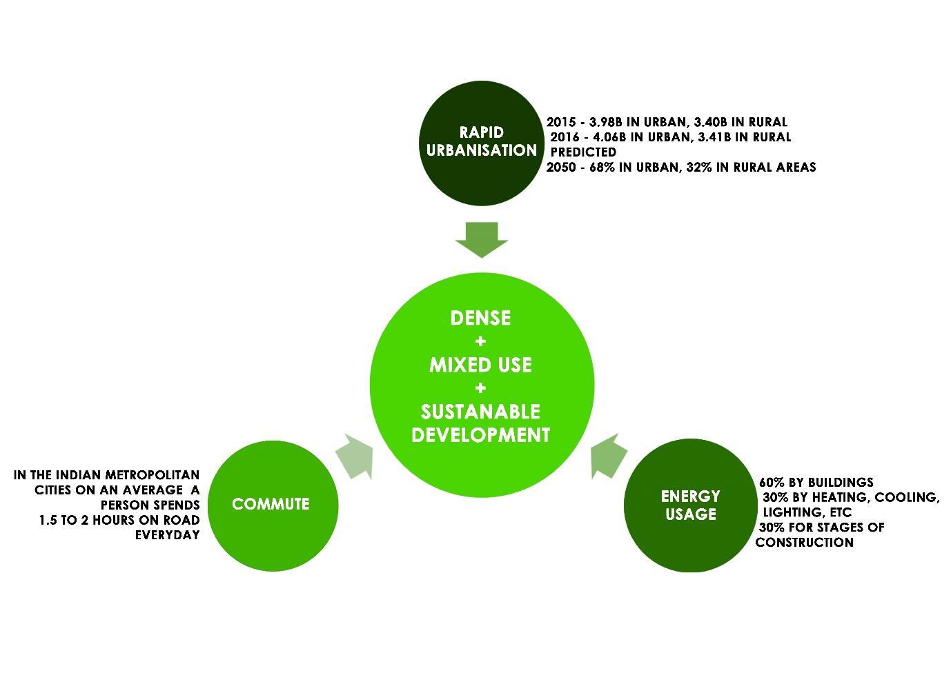
Need
● Increasing demand for business and residences
● Increase in travel time between amenities, workspaces, living areas, etc.
● Scarcity of land in urban areas
● Economic growth
● Technological advancement
● Innovation in structural system
8 Project 1 – Thesis Synopsis
Objectives
● To study how architecture contributes to the development of a city.
● To design a building which provides most of the living necessities in a single Development site, and to reduce the travelling time.
● To keep the balance between isolation and openness of building.
● To design a building which can inspire and catalyse the mixed use vertical urbanization.
● To get better and maximum use of land.
● Priority to sustainability, sustainable materials, functional requirements in building while integrating services to it.
● Lesser energy usage and carbon footprint using innovative energy Strategies.
● Designing a self sustaining building.
Scope
● Analysis and incorporation of urban habitat, urban issues, challenges of modern Society.
● Analysing and using new construction techniques, technology.
● Study and introduction of new energy strategies, sustainability techniques, Etc.
● Study of effect of a single architecture on urban sprawl and urban context.
● Proposal of a mixed use building prototype for specific climatic context.
9 Project
1 – Thesis Synopsis
● Cost factor may be more
Limitations
Case studies
Live case studies
Tidel park, Taramani, Chennai Bhikaji cama place, New Delhi City centre salt lake, Kolkata
Net case studies Linked hybrid, Beijing, China Shanghai tower, China
References
● Mixed use development in high rise context Papers (Elena M. Generalova1, Viktor P. Generalov1, Anna A. Kuznetsova1, and Oksana N. Bobkova1
● The tall building reference book (edited by Dave Parkar, Antony Wood)
● CTBUH (Council on tall buildings and urban habitat)
10 Project
–
1
Thesis Synopsis
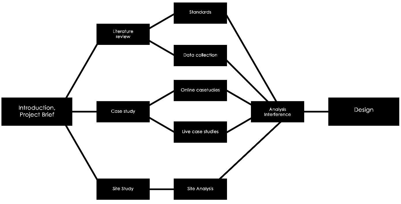
11 Project 1 – Thesis Synopsis Methodology Introduction Need Aim Objectives Scope Limitations Data Collection Case Study Site Selection, Analysis Design Process Report Writing
CHAPTER II
LITERATURE STUDY
12 Project 1 – Thesis Synopsis
Google leases 1 lakh sq ft office space in
Mumbai'sBKC
The total tenure of the lease is nine years and the contract includes a clause to cover 15% rental escalation every three years.
By Kallash Babar, ET Bureau I, 09.56 AM 1ST
MUMBAI: Internet giant Google Inc has picked up over 1 lakh sq ft office space in First International Financial Centre (FIFC) Tower, partly owned by the US private equity major Blackstone Group, in Mumbai's secondary business district Bandra Kurla Complex (BKC) through a long term lease, said two persons with direct knowledge of the development.
The office space spread over two floors in FIFC will attract monthly lease rental of Rs 275 per sq ft. The total tenure of the lease is nine years and the contract includes a clause to cover 15% rental escalation every three years.
"The lease transaction was concluded nearly a month ago. The fit outs are being planned now as Google is looking to shift into the new and bigger office as early as possible," said one of the persons mentioned above.
Google has a total of four offices in India, including its country headquarters in Hyderabad. In Mumbai, its current office spread over 20,000 sq ft is located at BKC's North Avenue Maker Maxity and the company is in the process of shifting from this complex to the five times bigger office in FIFC.
ET's separate email queries to Google, Blackstone and transaction advisor CBRE South Asia remained unanswered till the time of going to press.
The 12 storey FIFC Tower counts global companies, including Oracle and McKinsey & Company, as other key occupiers, while part owner Citigroup occupies a total of six floors. Citibank's India headquarters is housed in this tower.
Around 3 lakh sq ft, or nearly half of the 6.57 lakh sq ft building, is owned by global banking major Citibank Group.
Last year, Blackstone Group along with its partner Panchshil Realty, acquired over 3.60 lakh sq ft spread over six floors in this tower for about Rs 850 crore.
13 Project 1 – Thesis Synopsis The
Dec
economic times
11, 2018
The tower was developed by a consortium of US based investors including funds affiliated with Starwood Capital Group, India Property Fund sponsored by The Chatterjee Group & Vornado Realty Trust and Urban Infrastructure Real Estate Fund. These investors were holding the property through a consortium company, Earnest Trading Private Ltd (ETPL)
The US private equity major, according to media reports, is also in talks to acquire two office buildings in BKC, including Adani Realty's Inspire BKC and Radius Developers' One BKC in separate transactions for about Rs 1,900 crore and Rs 2,300 crore, respectively.
Interestingly, in one of the recent large lease transactions in BKC, Swiss multinational pharmaceutical major Novartis' India arm had picked up over 1 lakh sq ft of office space in Inspire BKC last year.
In early 2012; global banking major Citigroup had acquired around 3 lakh sq ft office space in this building for Rs 985 crore in the largest property deal then. Two Citigroup entities Citibank NA and Citigroup Global Markets had signed the deal then to acquire entire six floors of the 12 story FIFC Tower.
In 2013; software maker Oracle India had inked a nine year lease deal for 50,000 sq ft of office space in the building. US technology company Apple has also leased around 12,000 sq ft office space in it.
14 Project
1 – Thesis Synopsis
To create more space for jobs in Mumbai, FSI for offices doubled
28 April, 2018
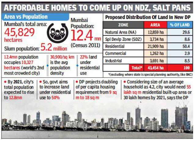
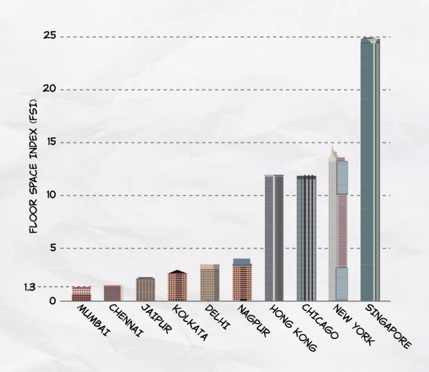
MUMBAI: Incentives for redevelopment of private buildings and doubling the buildable area for commercial space are among the key features of Mumbai's new Development Plan, which will replace the 1991 DP. Jointly addressing a press conference at Mantralaya on Wednesday, urban development Mumbai city secretary Nitin Kareer, municipal commissioner Ajoy Mehta and housing secretary Sanjay Kumar said the objective underlying the DP is to create eight million jobs in the new knowledge economy and 10 lakh affordable homes under “Pradhan Mantri Awaas Yojnaa” in metropolis struggling to cope with demands of population growth. Builders constructing commercial offices anywhere in the city will now get a floor space index of 5 compared to existing 2.5. FSI is the ratio of builtup area to the size of the plot. With barely any vacant land left for construction, planners are also banking on redevelopment to do the trick. In the island city, floor space index (FSI) of 3 will now be allowed for private residential societies and not just for redevelopment of old and dilapidated cessed buildings. Residential FSI in suburbs will however remain at 2.5. This comes in the wake of long years of discussion among planners on ways to "repopulate" the island city where census 2011 showed a 7 8% drop in population. Beneficiaries of the enhanced FSI regime will include builders controlling vacant mill plots in central Mumbai. FSI for such plots is currently a little over 2. For redevelopment of housing societies, DP offers 15% additional FSI free of cost. This, according to Kareer, will translate into "one extra room for each flat owner". State plans higher FSI near Metro stations, transport hubs
15 Project 1 – Thesis Synopsis The
economic times
Officials said they are hopeful that the new DP will be implemented to a large extent given the construction incentives. The rising population of the city and the low index of per capita housing Mumbai has an average of 30,900 people per square km, making it the second most over crowded city after Dhaka are among reasons cited for promoting redevelopment and providing higher FSI.
Reintroducing the Transit Oriented Development, the government plans to offer higher FSI near Metro interchanges, metro/railway stations and other transport hubs. Builders redeveloping Mhada properties like old and dilapidated buildings in the island city will now require consent of only 51% of tenants instead of 70% at present. This will be applicable to cluster redevelopment projects too. Special provisions will be framed for redevelopment of Gaothans, Koliwadas and Adivasi padas too. Similarly, new rules will be framed to enable redevelopment of buildings in the airport funnel zone. Shishir Baijal, chairman and MD, Knight Frank India said, "Significant increase in FSI for residential development, particularly in south Mumbai, and the unprecedented fillip for commercial development would bring much needed stability in the real estate market." Yomesh Rao, member, Practising Engineers, Architects, Town Planners said that by allowing 405 sq feet tenements for mill workers, government has also laid the ground for a minimum size for tenements in all categories
The article - -E3S Web of Conferences 33, 01021 (2018)
16
Project 1 – Thesis Synopsis
Elena M. Generalova1,*, Viktor P. Generalov1, Anna A. Kuznetsova1, and Oksana N. Bobkova1 Samara State Technical University, Institute of Architecture and Civil Engineering, 443001, Samara, Molodogvardeyskaya St, 194, Russia
Mixed Use development in High rise Context
Introduction
Massive world urbanization is accompanied by an alarming tendency for urban sprawl of city areas. Leading specialists in architecture, urban planning, economics, sociology, ecology, etc. are worried about it and try to find new, more rational urban planning and space planning solutions to meet the challenges of modern society. In these circumstances, the concept of «sustainable vertical urbanism» based on finding a totally new typology of tall buildings seems appropriate and develops rapidly. This typology is based on the principle of multi functionality. The term «multifunctionality» denotes the ability of a large system to perform many functions. In this paper, «functions» are urban services which are different types of activities in urban area (housing, industry, health care, trade, education, etc.). «Multifunctionality» as a phenomenon of urban environment has been studied by many researchers.
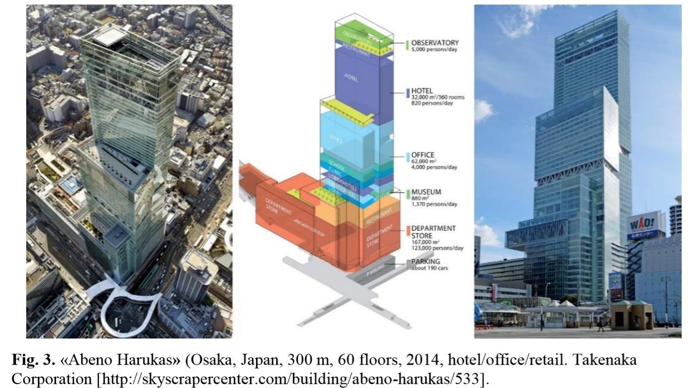
«Abeno Harukas», a complex built in Osaka in 2014, is considered to be the world's only building of this scale (300 m high), located directly above a train station (the Abenobashi Station). This train station, «Kintetsu», is located on the second floor, its capacity exceeding 70000 passengers per day. The complex is a real high rise vertical city with a maximum capacity of 110 000 people. It has 60 floors and 5 underground levels with various functions: a terminal station, a department store, an art museum, offices, a hotel, an observatory, a clinic, a school, parking spaces, etc. The department store occupies sixteen floors two underground levels and 14 floors above ground. The art museum is located on the sixteenth floor. There is a wide variety of works, including the Western and modern art, in it. The observation deck «Harukas 300» (Observatory) is one of the main attractions of this skyscraper, it is located on the 58 60 floors and holds a garden and an open air café. The internal volume of the building is filled with free public spaces that are also involved in the ventilation system and heat transfer of the whole construction. A stepped shape of the building allowed to create additional public green areas at different levels. The building construction is integrated with several technologies aimed at reducing emissions of carbon dioxide into the atmosphere, an innovative technology of urban biogas system for the building being among them. The tower is connected with the existing urban realm through public pedestrian bridges, built on different floors
17 Project 1 – Thesis Synopsis
Singapore complex «Marina One» (see fig. 5) will also make a significant contribution to the formation of a new typology of tall buildings after its completion. It is a high density, mixed use building complex in the heart of a new financial district. The basis of its concept is turning Singapore into a «Garden City». This concept is implemented through the creation of internal public space fringed by office buildings and housing accommodations, as well as a podium with shopping and entertainment function. It is the largest public Plaza in the Central Business District) which is supplemented by green areas at different levels of the complex. The perimeter formed by the buildings is not completely closed. The towers have a porous structure, which provides good air circulation, ensures natural ventilation and sustains a comfortable internal climate. Environmental sustainability and energy efficiency are achieved though introducing a variety of technologies: external sun protection devices and high performance glazing, centrally provided recycled water for toilet flushing, rainwater harvesting system, photovoltaic cells, and more. The complex is connected to the four lines of the Metro (MRT) and bus terminals.
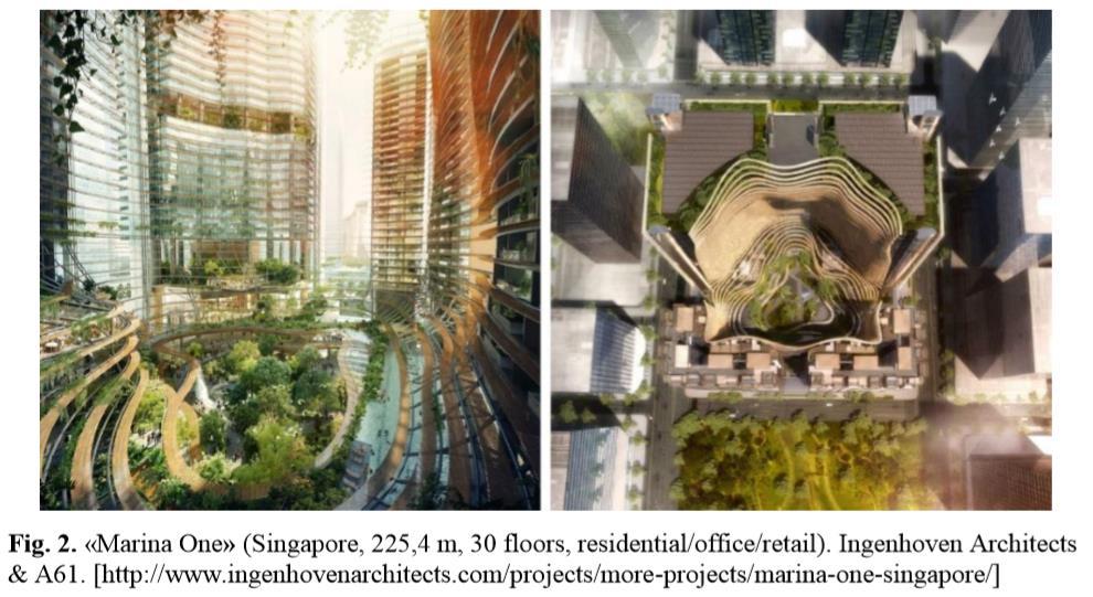
A complex
Hangzhou, 250.0 m, 60 fl.) is one of a few sites which are not that tall, with its unique space planning
18 Project 1 – Thesis Synopsis
named «Raffles City Tower Hotel Hangzhou» (China, City
decision. The building is in its final stages of construction and incorporates retail, offices, housing and hotel facilities. This project consists of two tall intertwining twin towers at the podium and a three storey underground parking. According to the designers, its characteristic feature is a close interconnection of the landscape aspect with the urban context (see Fig. 4). The project involves a huge amount of technical and engineering features that are implemented while using digital engineering through building information modelling, virtual construction planning and simulation

Conclusions
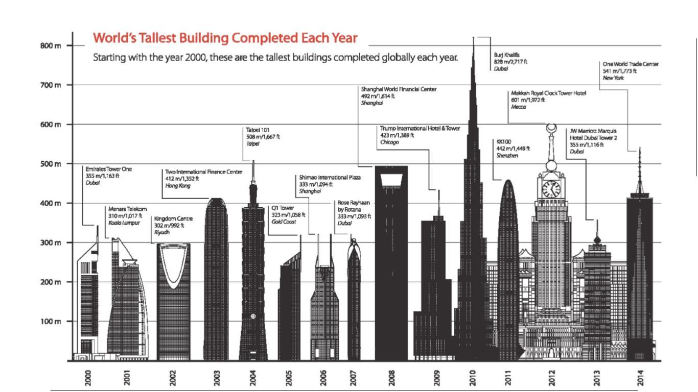
Summarizing the results of the analysis, it should be noted that the typology of mixed use tall buildings is being actively developing. This development is aimed at searching a modern interpretation of the concept of the vertical city, where people can live, work and relax. Even though today among mixed use tall buildings three buildings have surpass the mark of 600 m and there are 47 buildings above 300 m high, we can confidently say that «a race in the vertical direction» is not a philosophical basis of design concepts discussed above and implemented in the unique complexes under analysis. The most important criteria for the quality of these buildings architecture are the following approaches, techniques and methods of their integration into the urban environment: town planning; space planning; engineering; technological; integration through transport infrastructure; integration through the creation of public spaces and pedestrian links with surrounding buildings; because of a reasonable balance between the «isolation» and «openness» of different functional areas within buildings, etc. In conclusion, we would like to stress that a proper integration of mixed use tall buildings will allow to create a convenient and comfortable living environment and to improve environmental and economic status of existing cities.
Project 1 – Thesis Synopsis
19
ASHRAE DESIGN GUIDE FOR TALL, SUPERTALL, AND MEGATALL BUILDING SYSTEMS
 PETER SIMMONDS
CHAPTER 2
Architectural Design
ARCHITECTURAL CONSIDERATIONS
Although clearly the architect must respond to many of the real estate considerations outlined previously, there are concerns, which are primarily architectural in nature, to which the architect must respond that require input from other members of the design team. This guide addresses design issues for tall commercial buildings, which are very often mixed use, consisting sometimes of low level retail, office floors, residential floors, and hotel floors. As buildings get taller, there are different climatic effects which vary over the height of a building. The façade becomes important, not only because of the building size, but also because of how it responds to ambient conditions and contributes to the building’s heating and cooling loads. The façade also contributes to daylight harvesting.
It is commonplace to talk about a tall building’s design life (or at least those of its critical constituent parts) as being 25, 50, or 100 years. This is somewhat ridiculous, given
20 Project 1 – Thesis Synopsis
that there has never been a tall building of 656 ft (200 m) or greater dismantled at the end of its design life, (other than the events of 9/11) and some of them are now coming perilously close to, and beyond, this milestone. Recladding in the conventional sense is enormously expensive and wasteful of materials
ENERGY STRATEGIES
The fundamental strategy is to minimize energy usage, resource consumption, and plant space. Several factors affect this strategy, including the following:
• Minimization of solar energy gain to occupied areas through the façade/envelope
• Use of daylight to minimize lighting, and reduction of lighting when levels rise above the required level
• Maximizing re use of 60% or more of the building energy use
• Minimize fan and pump energy use, possibly by floor by floor service
• Utilization, if possible, of wind driven ventilation and cooling, as well as passive technologies.
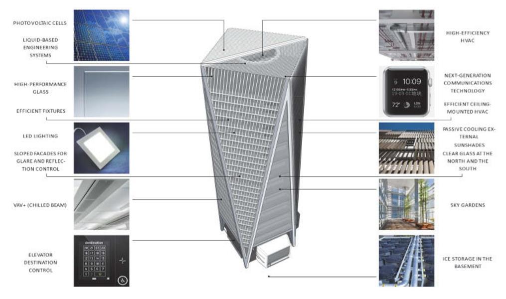
• Low energy terminal devices on occupied floors
• Allowing indoor temperature and humidity to fluctuate within comfort limits
21
Project 1 – Thesis Synopsis
Core Location
Most tall commercial buildings are designed with a center core that provides the maximum flexibility in the architectural subdivision of the floor. This is particularly true in the case of a multiple tenant floor. In addition, the use of a center core allows for the potential to improve the distribution of air conditioning ducts, because they can be extended to the floor from both sides of the core. This both reduces their size and shortens their length. The center core also offers structural advantages, with the stiff core providing a means to resist wind loads. A center core can also simplify the construction of the building in that it forms a central spine for the building with radial construction being added in all four directions, which can be accomplished more efficiently than if construction were more limited in how it could proceed. In some cases, (with small floors or with a building that is located against an existing building party wall), a side core will be designed for a building. As is discussed in Chapter 6, this can offer opportunities for introducing outdoor air directly to the floor if floor by floor airconditioning units are planned for the building. In buildings with very large floor plates, multiple cores may be necessary to reduce the travel distance to stairs or toilets.A cost disadvantage of multiple cores is the potential need for additional elevators.
SERVICE CORES
The position of service cores is important in any building but even more so in tall buildings. The core can be used for structural support and is also related to the building exterior, as most often ventilation air supply and exhaust systems are routed to and from the exterior to the core, where most mechanical rooms are situated. There are three types of commonly used cores:
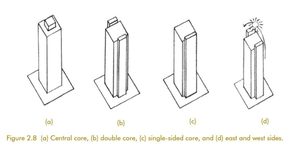
• Central core.
• Double core
• Single sided core
In locations where the climate is hot or hot and humid, it is suggested that the core(s) be located on the east and west facades to insulate the interior zones from the ambient conditions. There are studies that show that cooling loads have been kept at a minimum when using a double core configuration with glazing on the north south and south façade
22 Project
–
1
Thesis Synopsis
and cores on the east and west facades. The same designs can be applied in temperate climates.
Core Components
As a minimum, the core must incorporate the following entities:
• Fire stairs
• Vertical transportation elements, which is an arrangement of elevators and possibly escalators, including both passenger elevators and one or more service or freight elevators.
• Restrooms for both the male and female population and with provision to meet the Americans with DisabilitiesAct (ADA) requirements for both sexes
• Electrical closets
• Communication closets for multiple telecommunication providers.
• Local fan rooms (if floor by floor air conditioning equipment is the selected approach for the project) or large supply air and return air shafts (if central fan rooms are the selected approach for the project)
• Shaft space for other HVAC risers, beyond those for the local fan rooms or the supply and return ducts for the central fan rooms, such as toilet exhaust, general exhaust or dedicated smoke exhaust risers, and possibly kitchen exhaust risers
• Space for risers for the piping of the HVAC system and plumbing system as well as riser space for electrical distribution cable and the building management and fire alarm systems distribution cabling
STRUCTURAL COORDINATION
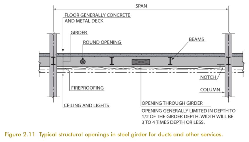
The structural engineer must make his selection of the structural design and floor slab system for a project with the active involvement of the mechanical, electrical, and fire protection (sprinkler) members of the design team, because the structural systems must be fully integrated with the ductwork, the HVAC piping (if any), the lighting, the electrical distribution system, and the sprinkler piping. This integration of the structural, mechanical, and electrical designs will determine the space requirements between the top of the ceiling and the bottom of structural slab of the floor above, which will be the starting point of the next floor. Most, but not all, tall commercial buildings in the United States have a steel structure rather than reinforced concrete.
The reasons for the use of steel include the following:
• Careful scheduling of the contractors will allow structural steel to be designed and ordered in advance of the final completion of architectural and mechanical, electrical,
Project 1 – Thesis Synopsis
23
and plumbing designs. This facilitates fast track construction, which allows the steel to be erected as soon as the foundations are complete, with a resultant reduction in the total construction time of the building.
• Structural steel construction is more readily and economically adapted to the long span, column free space desired by interior space designers and occupants, thus allowing for more flexible space designs and, in the case of a developer building, a potential increase in the building’s marketability.
• Structural steel construction provides the flexibility to alter the capacity or configuration of the structure to handle changes in loading by reframing or reinforcing the structural steel so that future occupant requirements may be accommodated. Such changes could be required by the introduction of floor to floor communicating stairs, elevators, dumbwaiters, or by the necessity to increase the load capacity of portions of a floor to support compact files, libraries, telecommunications equipment, or mainframe computer components.
• Structural steel will result in a lighter construction than would be the case with reinforced concrete construction. This allows savings in the cost of the foundations. The reduction in weight will also lower the seismic forces that the building will experience.
• The temporary shoring of a concrete floor for some time after the casting of a concrete floor is not required in structural steel construction. This allows the other construction trades to commence their work earlier.
The structural design of the building core presents challenges to the structural engineer because the core is usually designed to resist a large part of the wind and seismic forces to which the building will be exposed. This design requirement can be achieved by introducing bracingor deep girders ora combination of bracingand girders between columnsat the edge of the core. This is where the supply and return ductwork leave or enter the shaft or the local floor by floor fan room. It is also the location where the ducts are at their maximum dimension and where extra height will be required for fire dampers where they exit a rated shaft.
CONCLUSIONS CONCERNING FLOOR-TO-FLOOR HEIGHT
24
Project 1 – Thesis Synopsis
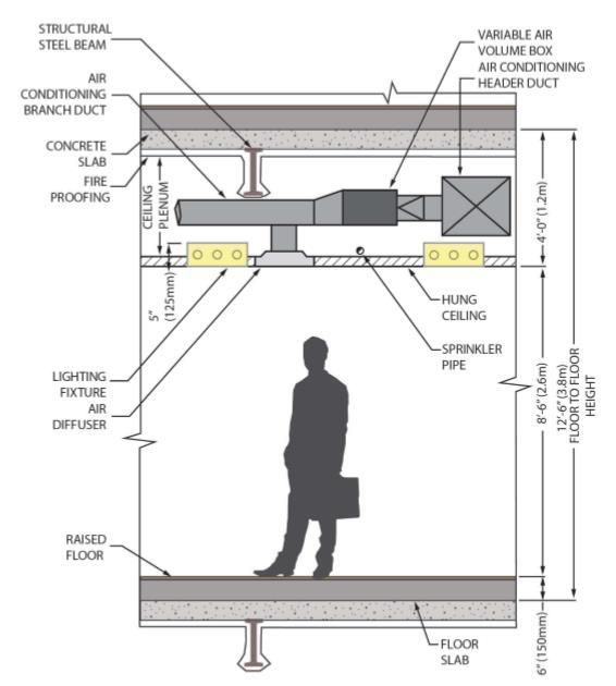
The floor to floor height required to meet the needs of a tall commercial office building with general office occupancy can usually be effected with a floor to floor height of 12 ft, 6 in . to 13 ft, 6 in. (3.8 to 4.1 m). This floor to floor height is achieved, for example, with the dimensions shown in Figure 2.16. The space from the bottom of the ceiling to the bottom of the slab of the floor above is 4 ft, 0 in. (1.2 m). This 4 ft, 0 in. (1.2 m) space would contain the lighting fixtures, ducts, sprinkler piping, and structural steel system supporting the slab. An increase (or decrease) in any of the elements shown in this figure will result in an increase (or decrease) in the floor to floor height. These conclusions do not include special areas in buildings such as data centers, trading floors, or dining facilities. A data center or trading floor will require a raised floor of as much as 24 to 30 in. (600 to 750 mm). Trading floors are normally open, partitionless spaces and very much call for a floor to ceiling height in excess of 9 ft (2.75 m) to allow line of sight communication between traders in various areas of the floor.1 This brief overview is intended to highlight the issues involved in determining the floorto floor height, a significant determination that has a major impact on the building cost because of the effect it has on the area and cost of the exterior wall of the building and the other vertical elements in the building. Accordingly, the entire design team must focus considerable effort on reducing the floor to floor height to a practical minimum for any tall commercial office building.
Facade
This guide addresses design issues for tall commercial buildings, which are very often mixed use, consisting sometimes of low level retail, office floors, residential floors, and hotel floors. Additionally, the matters discussed and the recommendations and comments that are developed, with various modifications, can be applied to other project types within the built environment. As buildings get taller, there are different climatic effects which vary over the height of a building. The façade becomes important, not only because of the building size, but also because of how it responds to ambient conditions and contributes to the building’s heating and cooling loads. The façade also contributes to daylight harvesting.
25 Project
–
1
Thesis Synopsis
That’s why a design guide like this is so important. There is so much research, so much unrealized potential in both passive and active systems operable façades, dynamic façades, energy generating façades, vertically vegetative façades, evapotranspirative façades, etc. that embrace, rather than resist, natural environmental conditions.
Though the building orientation is normally set by the available real estate and the architectural design, the tall building HVAC designer must remember to consider increased or decreased infiltration rates and solar loads affected by the planned building orientation. This can be especially important for megatall and supertall buildings, because infiltration from wind loads may be significant for very tall buildings, particularly for sites that may not have adjacent buildings or landscape that mitigates high winds. Existing (adjacent) buildings can provide significant shading for a newly constructed tall building. Though an adjacent tall building can reduce the peak and annual cooling load on the
FAÇADE SYSTEMS
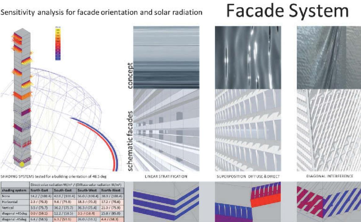
A high performance façade design is essential to minimize the solar cooling load and allow for efficient performance of air conditioning systems while enhancing indoor comfort and maintaining views. In general, the façade (building envelope and glazing) performs several functions:
• Protection from external environment of wind and rain
• Insulation of heat in summer and cold in winter • Reduction of solar radiation transmission
• Elimination of glare
Project 1 – Thesis Synopsis
26
• Minimizing infiltration and exfiltration
• Controlling levels of daylight
• Providing daylight beyond perimeter zone
• Aesthetics
• Easy to clean and maintain
• Allowing occupants to control their environment
• Provision of natural ventilation
• Mitigation of exterior to interior sound transmission
• Accommodation of daylighting design strategies to minimize electricity demand for lighting and reduce associated cooling loads
• Security considerations, especially and lower floors
• Blast design, especially at lower floors
• Impact resistant design in high wind areas as predicted by future climate modeling
The façade should be designed to minimize the solar gain to 10% to 20% of the incident radiation. Methods that can be used to achieve these levels include minimizing window area, ventilating the glazing, and/or articulation of the façade (e.g., placing the windows at a forward angle).
A double skin façade (as shown in Figure 3.2) could be used with fan coil, chilled ceiling, and chilled beam cooling systems and would have the return air directed to the floor of the perimeter and up between exterior and interior windows. The characteristics of the design are as follows:
• Reduction of solar transmission to 10% to 15%
• Outdoor air supplied at high level
• Return air through internal layer in which solar shades are located
• Solar shades and daylight level can be automatic or controlled by occupants
• The heated return air can be used to preheat ventilation (outdoor) air
• Minimal use of internal space
27
Project 1 – Thesis Synopsis
CLIMATE AND THE ATMOSPHERE
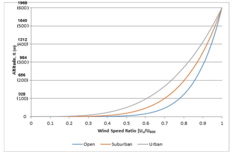
The design tall buildings has historically relied on ground measurements for climate data.In some cases, the climate information at grade has been extra polated upwards. However, as buildings have become taller the need for elevation specific meteorological data is becoming more important. This is especially relevant when the balance between sustainability and cost depends on good climate data to correctly size the HVAC equipment. The climate at 328 ft (100 m) above grade is not thesameas2000 ft (600 m). However, rarely does the design of the upper level of the building capitalize on that difference. Further, wind conditions at the top of a tall building are different. If sufficient data are known about this difference, It can be accounted for the design.
THEORETICAL DISCUSSION OF STACK EFFECT

28 Project 1 – Thesis Synopsis
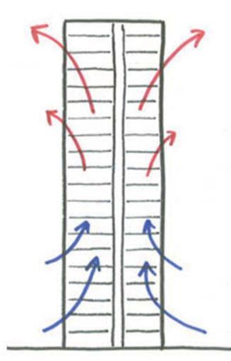
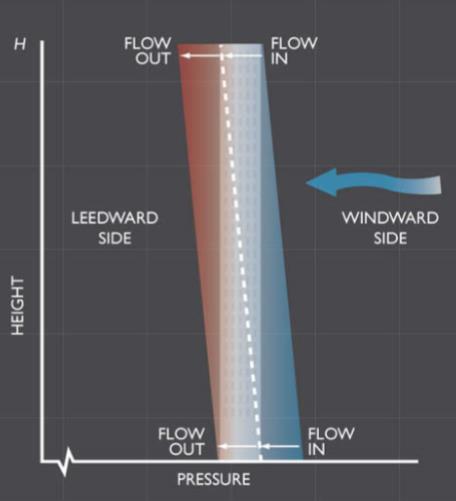
The ASHRAE discussion allows the calculation of the theoretical total stack effect for alternative temperature differences between the building and the area outside the building. It also points out that there is a neutral pressure level (NPL) in any building. This is the point at which the interior and exterior pressures are equal for a specific building at a given temperature differential The location of the neutral pressure level in any building is governed by the actual building, the permeability of its exterior wall, the internal partitions, as well as the construction and permeability of stairs and the shafts, including the elevator shafts and shafts for ducts and pipes that are provided in the building. Also influencing the neutral pressure level are the air conditioning systems themselves, with exhaust systems tending to raise the neutral pressure level in the building (thereby increasing the portion of the total pressure differential experienced at the base of the building).Any excess of outdoor air over exhaust air in supply air conditioning systems tends to lower the neutral pressure level in the building (thereby decreasing the portion of the total pressure differential experienced at the base of the building).
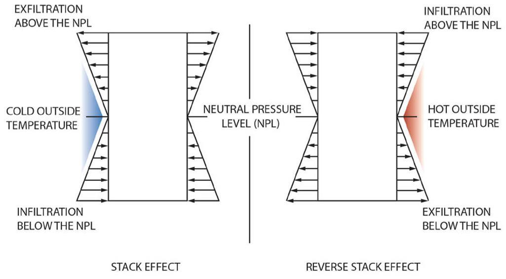
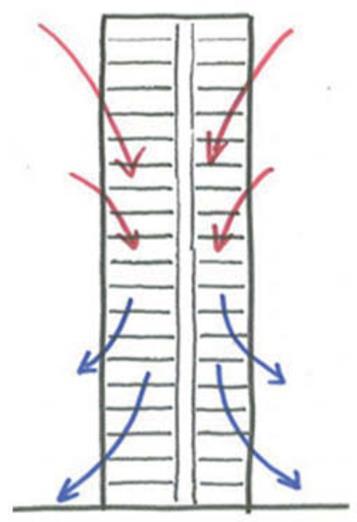
The neutral pressure level is the point in the building elevation where air neither enters nor leaves the building. The vertical movement of the air within the building will occur in the shafts and stairs in the building as well as any other openings that exist at the slab edge or in vertical piping sleeves at various locations that are less than perfectly sealed. The figure also indicates that the movement of air into and out of the building increases as the distance from the neutral pressure level increases.
29 Project
1 – Thesis Synopsis
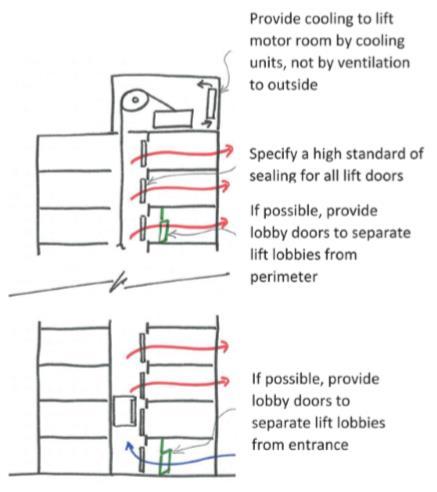
The elevator shafts are a large capacity route for air up through the building, and many of the elevators may reach the top of the building.Airflow though these elevator shafts should be reduced, and they should be separated from the accommodation using lobbies. In Moscow, two lobby doors are required between elevators and accommodation to promote segregation. Leakage to the outside environment can be avoided by mechanically rather than naturally cooling the elevator motor room.The sealing around the elevator doors should also have a high standard (target 0.6458 ft2 [0.06 m2]) leakage area round the door), taken from the British Standard for stair and elevator shaft pressurization.

30 Project 1 – Thesis Synopsis
Energy Modeling and Authentication
Nearly all new buildings are required to comply with energy codes, and therefore energy performance calculations are critical. This chapter looks at specifics associated with modeling tall buildings and compliance with various energy codes. It also provides information on the energy use index (EUI) of tall buildings and the expectations when designing and modeling such intricate buildings and systems. It is useful to look at implications of HVAC design of tall building in a broader range of climates, particularly warmer and more humid regions, in which much construction has occurred in the past and will occur in the forthcoming decade.
TALL BUILDING ENERGY CONSUMPTION
Energy simulation can provide the architect and client with information regarding the massing of the building and the orientation to improve its thermal and natural daylight capabilities. This information would also guide the preliminary energy goals for the building. This is usually determined byASHRAE/IESNA Standard 90.1, Energy Standard for Buildings Except Low Rise Residential, and other applicable standards and codes. Setting goals also helps outline possibilities in providing efficient building design solutions that consume less carbon than the standards or codes allow.A preliminary report should include any relevant solutions or possibilities for the building and its systems. The report should also remove any nonplayers, minimizing the alternatives so as not to tax the available budget. With the relevant simulation programs, guidance can be provided at an early stage on, for example, glass types and systems. The next plan as the project develops is to analyze the buildings’ performance using simulation programs (usually DOE 2 [LBNL 2005]). Once the base line has been determined, energy conservation measures can be assessed. When the base line and alternatives have been developed, probably the most difficult stage emerges: obtaining costs for the different alternatives from the contractor. Should a quantity surveyor be employed, this will simplify matters but not necessarily provide a usable solution.
Vertical Transportation
Every tall building will require a vertical transportation system.The vertical transportation system will always include elevators and may include escalators. Escalators, when included, will meet the limited and special needs that may develop in a building, to allow the efficient transferring of people from an entrance level to a main lobby that exists on the floor above the entrance level. Escalators are also frequently included to move large volumes of people to cafeteria levels if they are located below the entrance lobby level. In addition, escalators will be required if a sky lobby with double deck elevators, discussed later in this chapter, is part of the design for a building. In most tall buildings, escalators will not be required. The selection
Project 1 – Thesis Synopsis
31
of the elevators, including their arrangement within the core, is of critical importance to the architect.While there are rules of thumb, discussed later, that will indicate, for concept design purposes, the number of elevators required based on the area or diversified population in a building, the application of these rules of thumb is not appropriate in the actual design of a tall commercial building due to the multiple arrangements and types of elevators available and the inherent complexity of the possible solutions that can be used in the actual design. The need for an independent, experienced elevator consultant is a matter that must be understood by the developer who is putting together the design team. Once a building is finished with a given arrangementofelevators,itisnotpossibletosignificantlyalterorimprovetheperformance ofthe system that has been installed. Except for minor tweaking, it cannot be changed insofar as the arrangement, the number of cabs, and the floors that are served by each cab are concerned.
SKY LOBBY CONCEPT
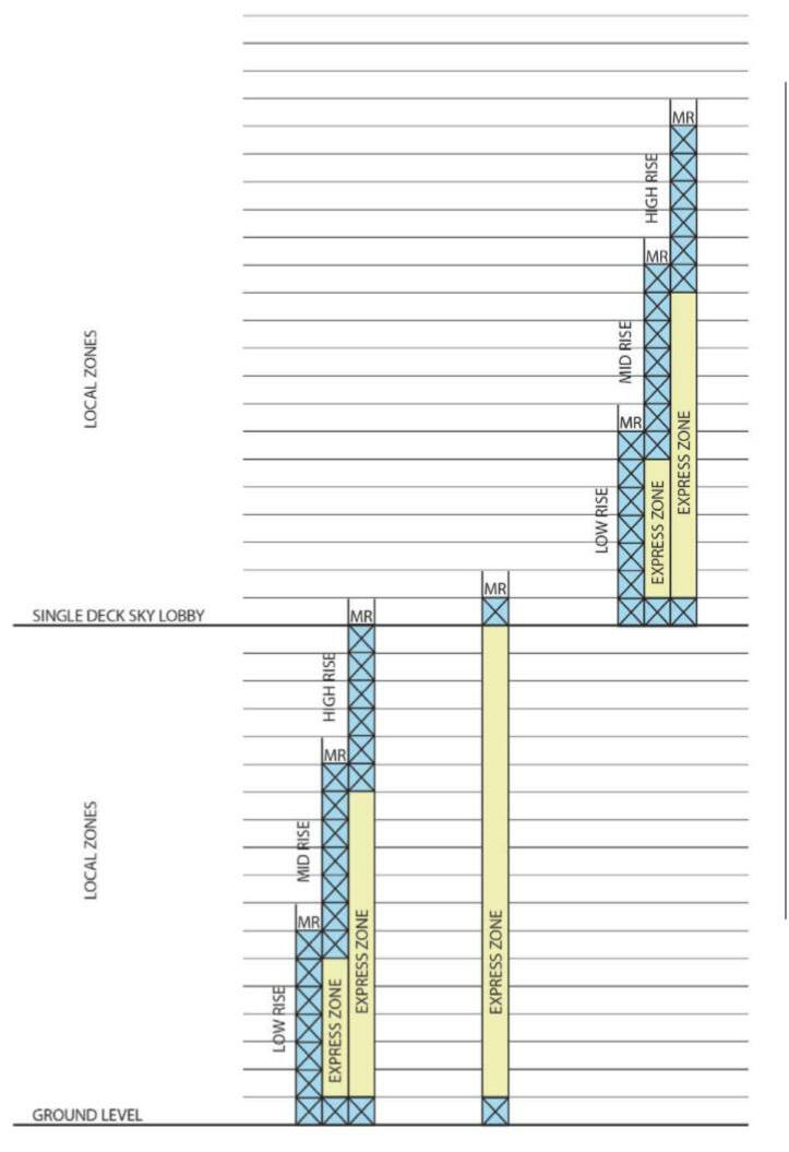
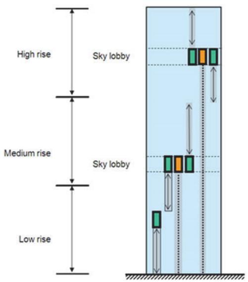
In the sky lobby concept, high speed, high capacity shuttle cars transport passengers from the entrance level to a sky lobby located at the point where the passengers transfer to a second bank of elevators that serve the local floors above the sky lobby. Figure 11.1 shows in cross section an arrangement of elevators for a building with a single sky lobby.The lower half of the building is served by local elevators configured with low rise, mid rise, and high rise groupings. An express shuttle is available to take building occupants to a single level sky lobby where they will have a second arrangement of low rise, mid rise, and high rise local elevators. This configuration effectively has two standard buildings one on top of the other. This process in a supertall building of 80 or 90 stories or more could be repeated with passengers being express carried to a second sky lobby from the entrance level where they transfer to the bank of elevators that serve the floors they are going to in the building. In this case, the result would be a building that, in effect, would resemble three
Project 1 – Thesis Synopsis
32
standard buildings being stacked one on top of the other, each of the buildings having its own independent local elevator system served from the entrance level by the express shuttle elevators.
DOUBLE DECK ELEVATORS
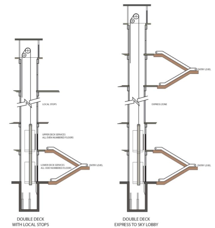
An alternative to the sky lobby that has found application in tall buildings is a double deck elevator. In this alternative, a dramatic reduction in the area required by the elevator shafts in the building core is possible. Each elevator is two cabs high and each cab serves every other floor. Initially upon departure from the main lobby, one serves all of the even number floors, the other every odd number floor. The two floors at the entrance level are connected by escalators to allow passengers access to the cabs serving their desired destination floors. After the elevator makes its first stop in response to a “landing” call, the operational system changes and allows either cab to serve an even or odd numbered floor. This results is a system where the two elevator cabs use a single hoistway, which in turn results in a more efficient core design for the project, because the number of elevator shafts is reduced.This benefit is obtained through a substantial premium in the cost of the elevators. Figure 11.3 shows in cross section the doubledeck arrangement in a building with local floor stops.
33 Project
–
1
Thesis Synopsis
Why tall buildings?
Three Generations of High Rise Buildings
Since the first appearance of high rise buildings, there has been a transformation in their design and construction. This has culminated in glass, steel, and concrete structures in the international and postmodernist styles of architecture prevalent today. The following information, adapted largely from High Rise/Fire and Life Safety 37 by the late John T. O’Hagan, former fire commissioner and chief of the New York City Fire Department, describes three generations of high rise buildings in the United States since their inception.
First Generation - The exterior walls of these buildings consisted of stone or brick, although sometimes cast iron was added for decorative purposes. The columns were constructed of cast iron, often unprotected; steel and wrought iron was used for the beams; and the floors were made of wood. “ In a fire, the floors tend to collapse, and the iron frame loses strength and implodes. ” Elevator shafts were often unenclosed. The only means of escape from a floor was through a single stairway usually protected at each level by a metal plated wooden door. There were no standards for the protection of steel used in the construction of these high rises.
Second Generation - “ The second generation of tall buildings, which includes the Metropolitan Life Building (1909), the Woolworth Building (1913), and the Empire State Building (1931), are frame structures, in which a skeleton of welded or riveted steel columns and beams, often encased in concrete, runs through the entire building. This type of construction makes for an extremely strong structure, but not such attractive floor space. The interiors are full of heavy, load bearing columns and walls. ” As Brannigan described them, Pre World War II buildings were universally of steel framed construction. Floor construction and fireproofing of steel were often of concrete or tile, both good heat sinks and slow to transmit heat to the floor above. The construction was heavy but no feasible alternative existed. Relatively small floor areas were dictated by the need for natural light and air. Advertisements for the RCA Building in New York proclaimed, “ no desk any farther than 35 feet from a window. ” This limited both the fire load and the number of occupants. The typical office was quite spartan, though executive suites and eating clubs often were paneled with huge quantities of wood. Nevertheless, most fire loads were low.
Each floor was a well segregated fire area in these buildings. Wall construction was frequently of wet masonry, joined to the floor so that there was an inherent firestop at the floor line. Masonry in the spandrel area (the space between the top of one window and the bottom of another) was adequate to restrict outside extension. In these buildings vertical shafts were enclosed in solid masonry with openings protected with proper enclosures. Fire department standpipes of adequate capacity
34 Project 1 – Thesis Synopsis
were usually provided. These were wet and immediately pressurized by gravity from a tank in the building.
Exterior fire tower stairways with an atmospheric break between the building and the stairway, the finest escape device available, were provided in many of the buildings. Such a stairway can be compared to an enclosed tower located away from the building which is reached by a bridge open to the weather, so that smoke cannot pollute the tower.
Windows could be opened in buildings of this era. This provided local ventilation and relief from smoke migrating from the fire. The windows leaked, often like sieves, therefore there was no substantial stack effect. In this generation of buildings, developments such as the following occurred :
● The use of noncombustible construction materials that reduced the possibility of the collapse of structural members during a fire.
● The inclusion of assemblies rated for a particular fire resistance. The enclosure of vertical shafts with protected openings.
● The use of compartmentation.
Third Generation - Buildings constructed from after World War II until today make up the most recent generation of high rise buildings. Within this generation there are those of steel framed construction ( core construction and tube construction ), reinforced concrete construction, and steel framed reinforced concrete construction.
Project 1 – Thesis Synopsis
35
CHAPTER III
CASE STUDIES
Mixed Use development at Mumbai
36 Project 1 – Thesis Synopsis
BLUE RIDGE
Live case study
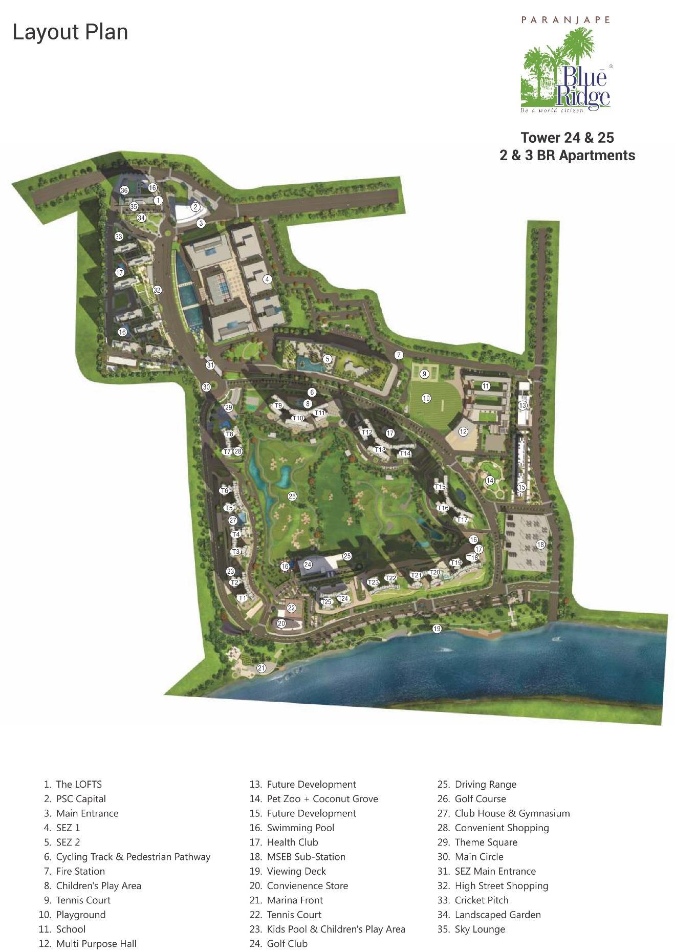
Architect AVA architects Designed in 2007 Built in 2018 and ongoing Built up Area 148 acre Location Hinjewadi, Pune
37 Project
1 – Thesis Synopsis
Introduction
AVA enabling worked with Arcplus, China (formerly ECADI) to create an outline masterplan for the Blue Ridge Township at Hinjewadi, Pune. The process included specific objectives and procedures that promoted design quality, and a robust design strategy. Architects were able to match the promoter's vision. Blue Ridge is an exciting mixed use scheme which has played a major part in transforming the area. It provides in one township community, health and commercial facilities, IT sector, offices together with residential apartments.
The new IT hub of Pune Blue Ridge consists of a Special Economic Zone (SEZ) and residential luxury that is unparallel. The Blue Ridge SEZ will cater to the new age IT/ITES industries and offer work and leisure facilities that are unheard of. Also It is a township that blends the best in residential housing with the best commercial space on offer.
Location
Hinjewadi, Pune, India. Blue Ridge town is located along Mula river. It is located in west side of Pune city but officially outside the city limits. Nearby villages are Hinjewadi, Maan, Mahalunge, Marunji
Spaces
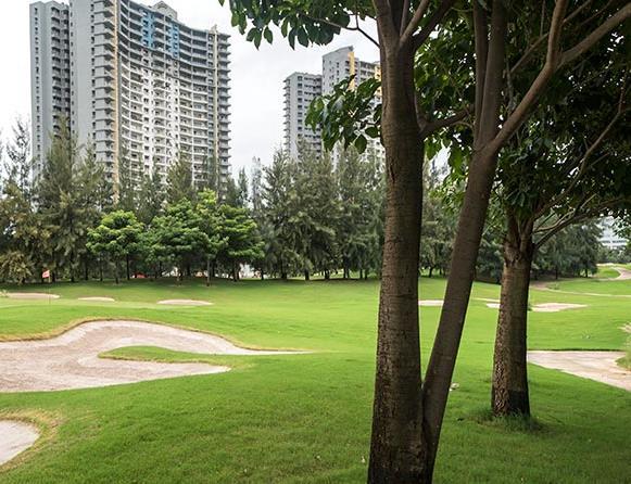
Blue Ridge is located in Hinjewadi. The total site area is 138 acre. The apartments have range of 1, 2, 3, 4 and 5 BHK apartments and duplexes set in 25 storey high towers. There are total 31 buildings of apartments. The multiplex and mall is in one building and height of building is 24.0 m. The school is an international school with height of 18.0 m. It has the 9 hole golf course. The river side is developed as an entertainment zone. It contain garden, play area, restaurant, etc.
38 Project 1 – Thesis Synopsis
The project master planning evolved with twenty seven residential towers ranging from 80 to 100 meters tall built around a golf course and facing the river. A school and adjoining I.T. Park enables residents and children to walk to school and work respectively. A Shopping Centre and township office complete the scheme.
Township amenities
Shopping
Polyclinic
Theme Square
Tennis court
Jogging track
Barbeque zone
Meditation place
Golf course
Ambulance with paramedics
Coconut groove
Pet Zoo
Blue Ridge public school
Football/Cricket ground
Multipurpose hall/Badminton court
Sector amenities
Open lawn area with landscape garden
Membership to Blue Ridge Golf Club having(Swimming pool, multipurpose hall and fitness center)
Kids corner
(*payment terms and condition of Blue Ridge golf club are applicable)
Society office
Building amenities
Multilevel car parking
CCTV camera
Smart lighting solution for living and master bedroom
Video intercom facility
Garbage chute
Elevator
39
Project 1 – Thesis Synopsis
Piped Gas system
Generator backup to elevator, water pumps, common light and 1kVA every flat
Specifications
Flooring and dado work
Vitrified tiles of 800x800mm for Living, Dining, Kitchen and Bedrooms
Floor tiles of 300x300mm for toilets
Dado tiles in toilet up to lintel level
Dato tiles above cooking platform up to lintel level Kitchen
Kitchen
Black Granite kitchen platform with stainless steel sink S.S. Sink make
Modular Kitchen with provision for dish washer modular kitchen make
Doors
Main Door Flush door with laminate on both sides
Laminate
Door
All internal door with flush door with laminate finish on both sides
Laminate
Powder coated aluminium sliding door shutter with glass
Electrical and plumbing
Concealed wiring with modular switches
Concealed plumbing with C.P. plumbing fixtures
Sanitary fittings
Electrical and plumbing provisions for water heater and electrical provision for exhaust fan in all toilets
Electrical and plumbing provisions for water purification and electrical provision for exhaust fan in kitchen
TV and telephone points in living room and all bedrooms
AC electrical points in living and all Bedrooms
Windows
Powder coated aluminium sliding window
40
Project 1 – Thesis Synopsis
Paintings and finishes
All walls excepts balcony, toilet and dry balcony will have gypsum punning and plastic emulsion paint Paint
1 – Thesis Synopsis
41
Project
42 Project
–
1
Thesis Synopsis

43
44 Project
–
1
Thesis Synopsis

45 Project
–
1
Thesis Synopsis
LINKED HYBRID
Net case study
Architect Steven Holl
Structural Engineer
Nordenson and Associates Designed in 2003 2005 Built in 2005 2009 Built up Area 220,000 m2 Location Beijing, China
46
Project 1 – Thesis Synopsis
Introduction
The urgent need for housing in a country with high population densities like China, exacerbated by a booming economy and population displacement, especially from the dam area of the Yangtze River (Yang Tse Kiang), let little space and time to design creatively.
Peking (Beijing), with more than 17.4 million inhabitants and a growing middle class eager to change its Mao era homes with new departments, has been in the last decade as a whole neighbourhoods of lower house, houses with patios in old streets and alleys known as hutong, have given way to new housing blocks, alone or in closed groups which have moved most middle income families, with the limited financial means Chinese or foreign makers to restore or modernize old boxes patio.
In this climate, with the design and development of complex Linked Hybrid, Steven Holl Architects has created a new and good concept of flats come.
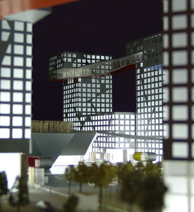
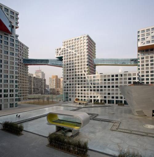
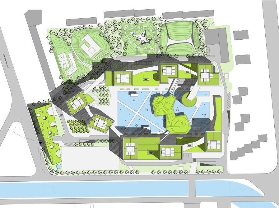
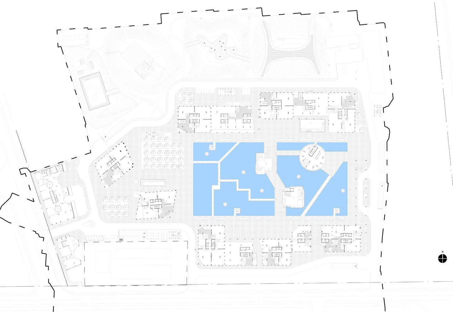
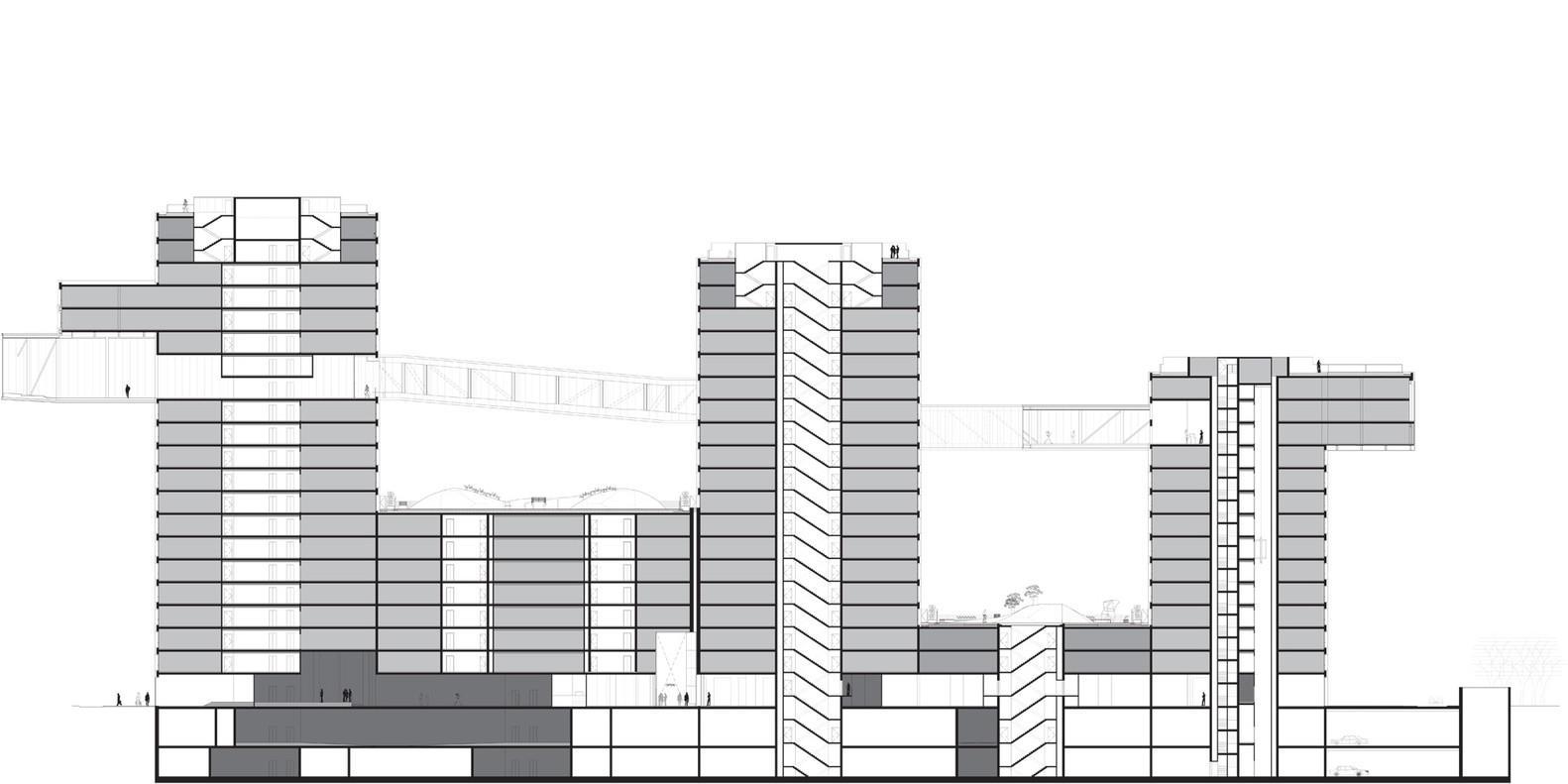
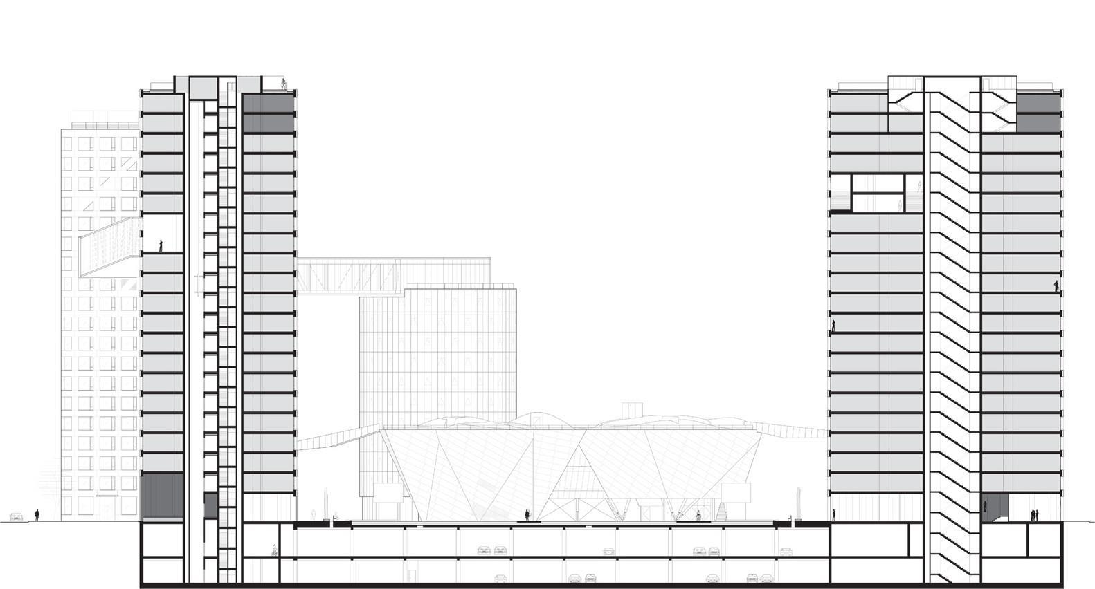
With an area of 220,000 square meters housing complex consists of eight towers linked by eight bridges and also hosting a variety of public services.
Location
The resort is located along the perimeter of the ancient city of Beijing, at the foot of the Second Ring Road of Beijing, the city now has six, and 15 minutes walk from a subway station. Between the late 50’s and 60 Mao Zedong area earmarked for industrial use, so to build this modern green building did not have to bring down any house, only one factory. “I would not work on a project that requires people to be moved,” said Holl.
47 Project 1 – Thesis Synopsis
Concept
This “city within a city”, with numerous streets around, above and across multiple spatial layers, is one of its main objectives the concept of “public space within an urban environment, and can support all activities and programs for the daily lives of over 2500 people.
Holl is the Linked Hybrid as a “city within a city” and says it represents “a change of value” in the design of tall buildings. “This is not to be high,” he says, “is about being sustainable and making connections with the urban context.”
Spaces
To counter the current trends of urban development in China, the resort creates a new model of urban space, opening and inviting the public from all angles. The entire complex is an urban space in three dimensions in which both buildings are in the basement, at ground level or on it, they merge and fuse into one body.
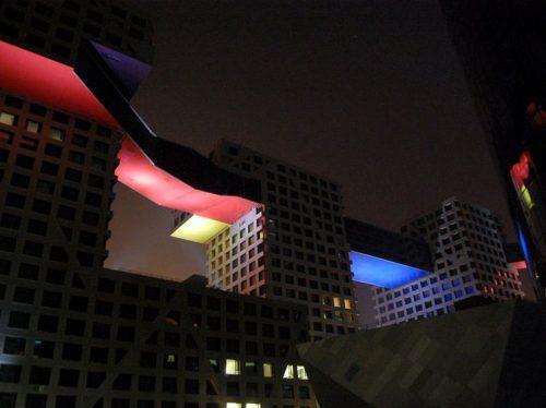
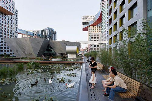
Has 644 apartments, commercial and recreational facilities open to the public green area, movie, nursery, school, parking and a hotel.
Ground floor and intermediate levels
The ground floor offers a number of passages open to all persons, residents or visitors. These tickets guarantee a micro urban scale with shops surrounding the central reflective big pond. All public functions of the ground floor including a restaurant, entrance to the hotel, Montessori school, kindergarten, and cinema among others, have connections with
48 Project 1 – Thesis Synopsis
surrounding green spaces which in turn goes into the building. The elevator moves like a cut “jump” to another set of tickets at a higher level.
At the middle level of the lower buildings, green roofs offer quiet spaces for recreation.
Apartments
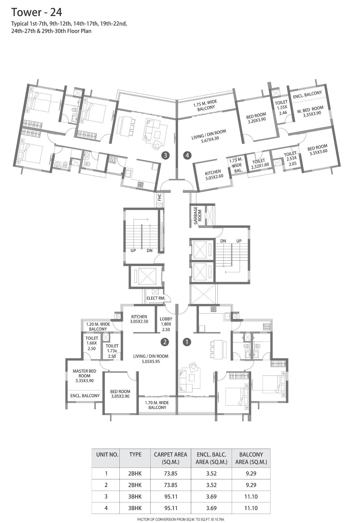
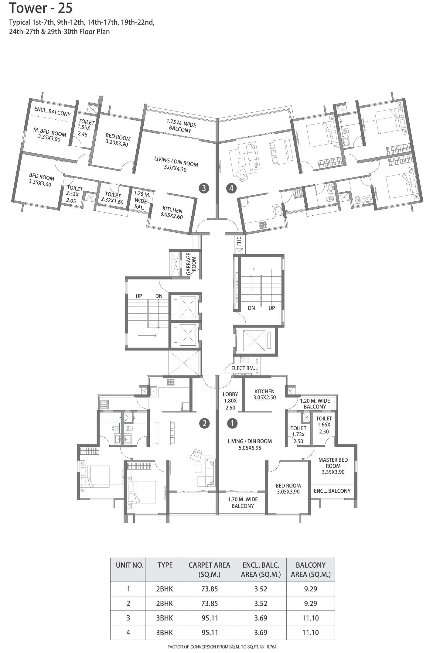
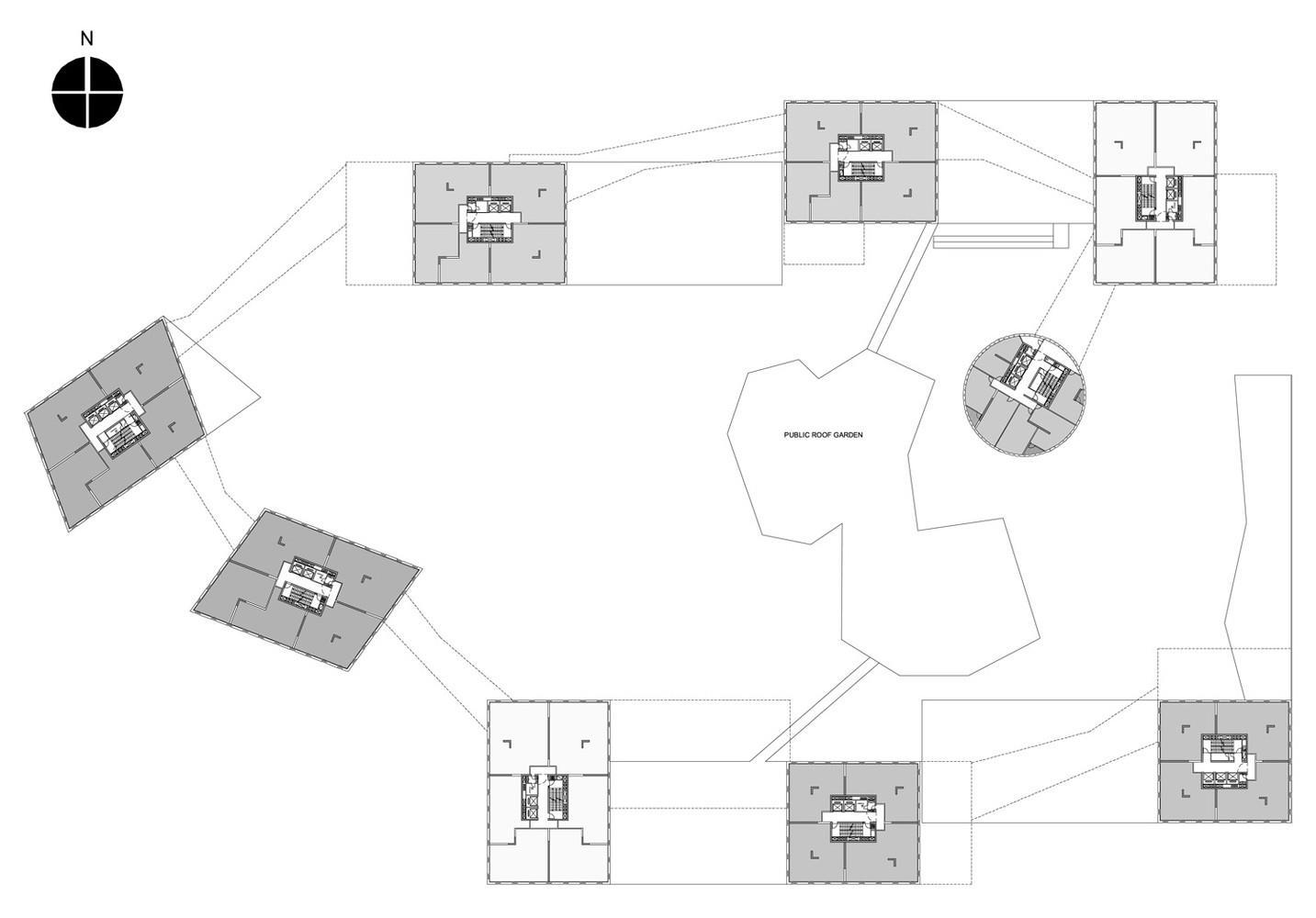
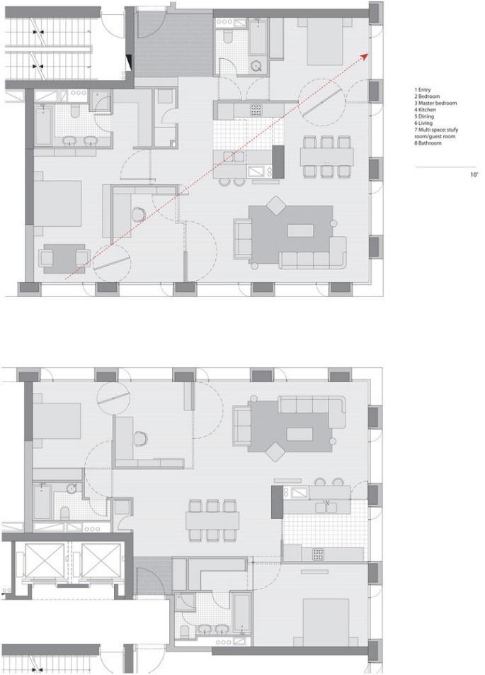
Four apartments occupy each floor, so every unit is installed in its own quadrant and has views in two directions. Typical units range in size from 74 to 150 square meters and one to three bedroom. The absence of columns in their environment allows various uses.
The windows open on two fronts allowing cross ventilation, but the buildings also provide mechanical ventilation and radiant cooling.
Upper Level
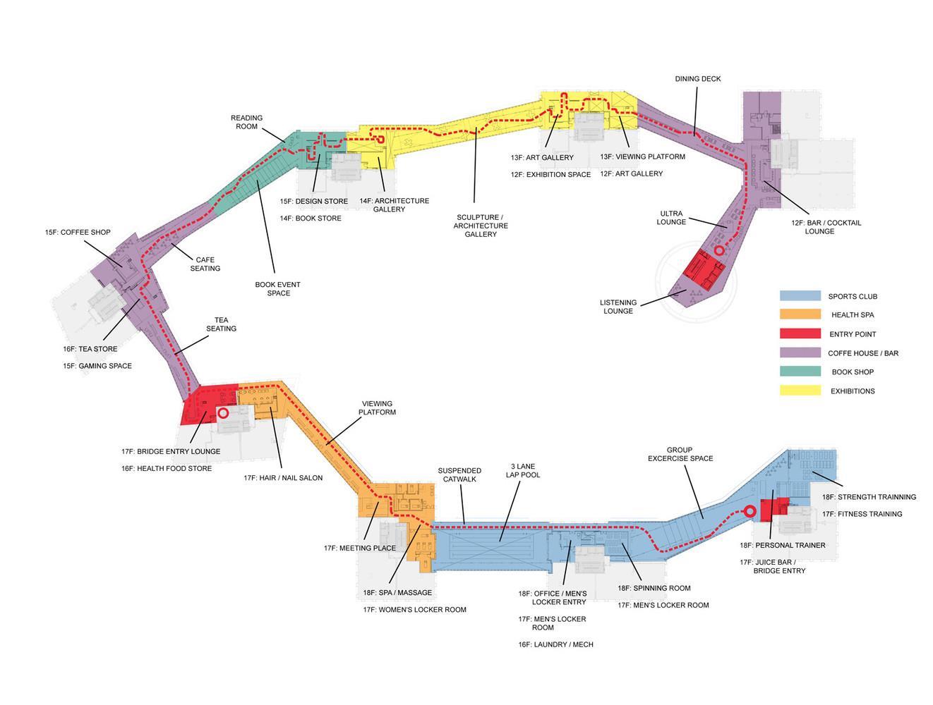
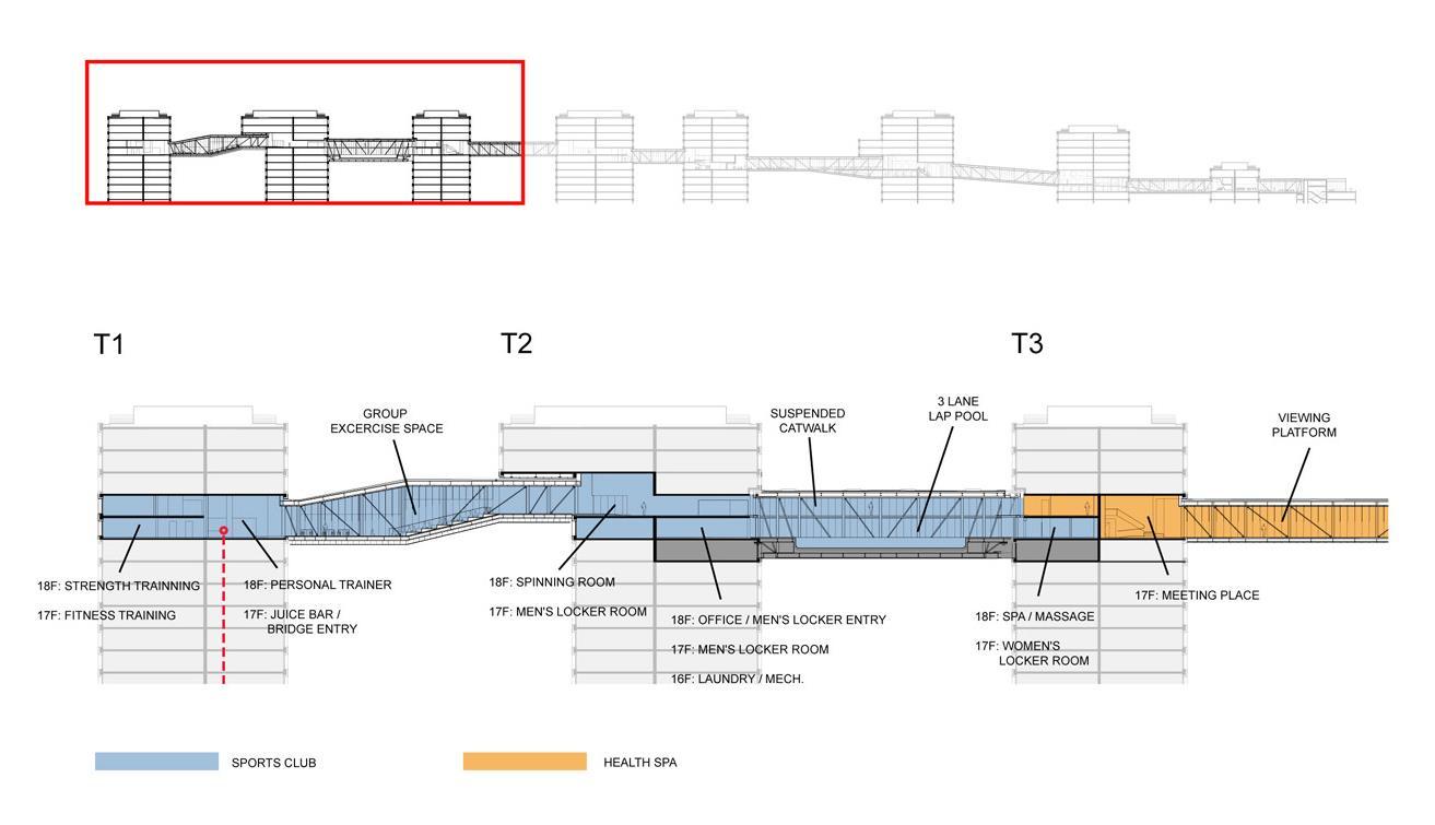
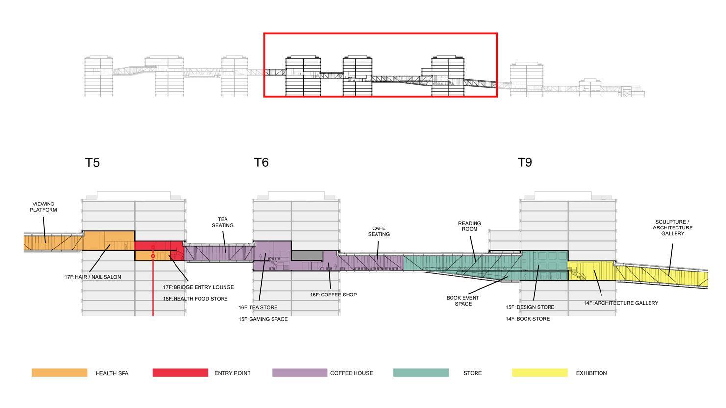
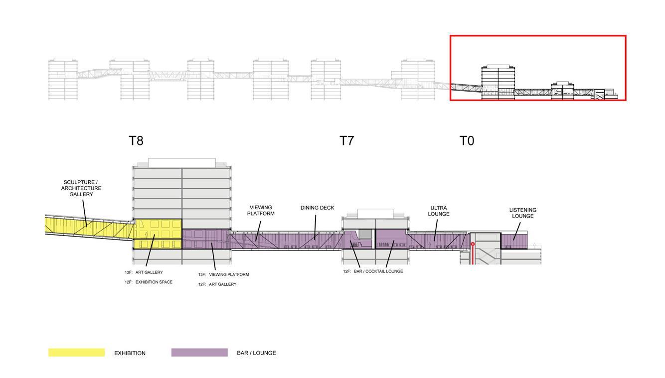
From level 12 to 18 a series of covered bridges and multi function pool, a gym, a café, a gallery, an auditorium and a mini hall connecting the eight residential towers and for the hotel, offering spectacular views over the city. At the top of the eight residential towers gardens that serve as a roof insulation are connected to the attic.
Structure
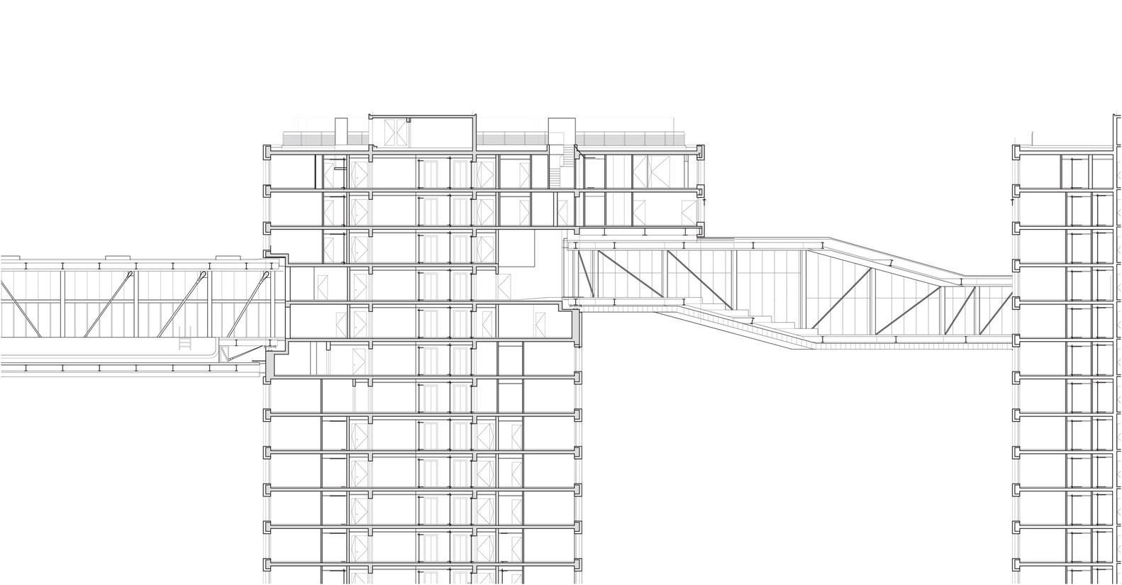
In collaboration with structural engineers and the Chinese Academy of Building Research, Holl’s team has raised the eight towers hormibón exoskeletons that allow you to eliminate interior columns in the apartments. As a result the building envelope is the structure, a scheme that designers expressed in diagonal lines that reflect “the seismic forces” on the facades.
49 Project
–
1
Thesis Synopsis
Materials
Heating and cooling
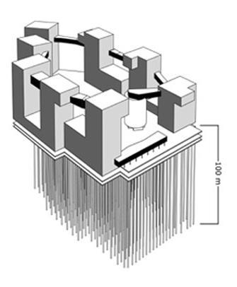
Six hundred and fifty five geothermal wells dug 100 meters deep, provide 5,600 kilowatt hours of energy annually in the summer and 3,700 kilowatt hours in winter, enough to handle the most complex heating and cooling, distributed through the concrete slabs of the departments. A security system is activated when more power is needed. No heating boilers or electrical air conditioners, making the Linked hybrid one of the largest green residential projects in the world.
Linked Hybrid makes use of a technique called displacement ventilation, in which air that is slightly below desired temperature in a room is released from the floor. The cooler air displaces the warmer air, causing it to be released from the room and resulting in a cooler overall space and a fresh breathing environment.
Water consumption
A plumbing system recycles waste water for irrigation of green areas, while the large central reflecting pool functions as a retention pond. With water becoming an increasingly precious good in Beijing, the Linked Hybrid objective is to reduce by 41% potable water use
Bridges
The emblematic icon of the project, glass and steel bridges, which vary in length between 20 and 60 meters were assembled on the ground and then hoisted into position. These bridges were mounted on large bearings that connect the towers, and allow them to move independently during an earthquake.
50 Project 1 – Thesis
Synopsis
Colour
The overhangs of the flats located on the top of the five towers are steel and as it has done in other projects, Holl introduced colour in the soffits of windows and on the bases of the elements cantilever bridges, membranes used polychromatic colours with Buddhist temples which uses the I Ching to determine the pattern. To emphasize the colours have been used MaxiWoody 150W metal halide with different type. s of optical, Super Spot, Spot and Flood.
51 Project
1 – Thesis Synopsis
52 Project
–
1
Thesis Synopsis
53 Project
–
1
Thesis Synopsis
54 Project
–
1
Thesis Synopsis
55 Project 1 – Thesis Synopsis

56 Project
–
1
Thesis Synopsis
57 Project
–
1
Thesis Synopsis
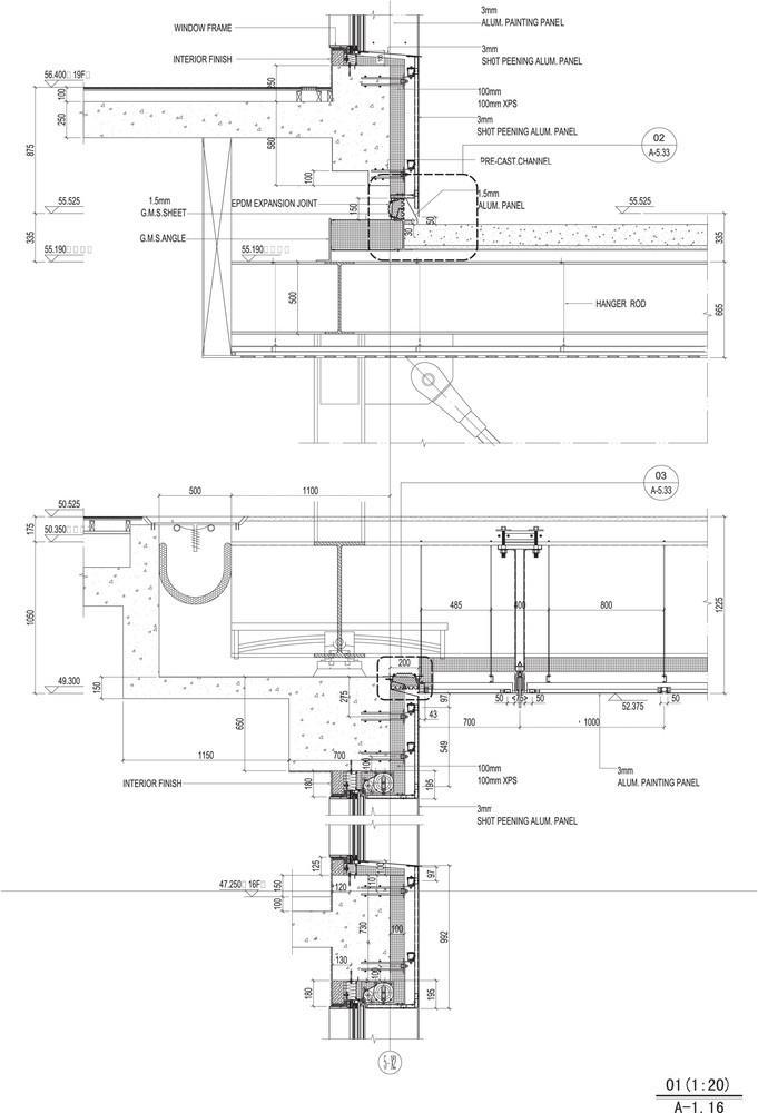
58 Project
–
1
Thesis Synopsis
Net case study
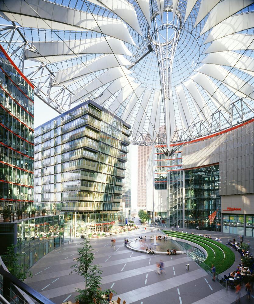
SONY CENTER, BERLIN
Architect Helmut Jahn
Designed in 1996 Built in 2000 Built up Area 35000 sq.m Location Berlin, Germany
59 Project
1 – Thesis Synopsis
Introduction
Unique in its concept and distribution, this building was not conceived by its creators as a separate building in the city but as a fundamental part of your body. One of the effects sought in this creative project was that upon entering the property the visitor had the feeling remain within the city but with a virtual tap where you can breathe freely and transit activity of the Berlin population. This effect makes well made set a unique construction that blurs the boundaries between public and private space in a modern city.
Location
The Sony Center is located in the historic heart of Berlin at Potsdamer Platz district of Mitte.
Concept
According to Helmut Jahn: “In the reconstruction of Berlin, the Sony Center represents a new vision of order and technique. The brightness, both natural and artificial, is the essence of design.
The Sony Center is bright, not illuminated. The facades of glass and the roof material act as moderators of both the daylight and the artificial. With its characteristics of transparency, reflection and refraction of light, there is a constantly changing images and effects of both day and night, affecting not only the appearance but also maximizing comfort and minimizing the use of energy resources. ”
The Sony Center is a “Kulturform”, a new form of culture for a millennium in which the high and serious business of entertainment is a real challenge in the art of classical music, theater and painting.
Description
Integrating the lounge and breakfast room in the old Kaiser Hotel Esplanade, the architects retained in the new construction, the European
60
Project 1 – Thesis Synopsis
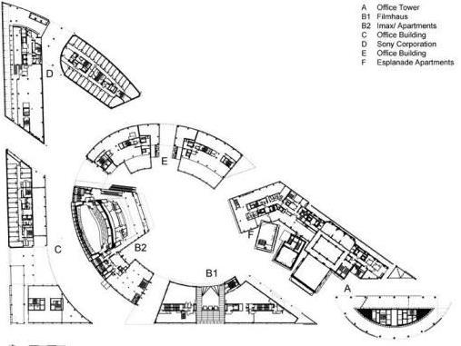
headquarters of Sony consists of seven buildings surrounding a central courtyard with a roof of canvas.
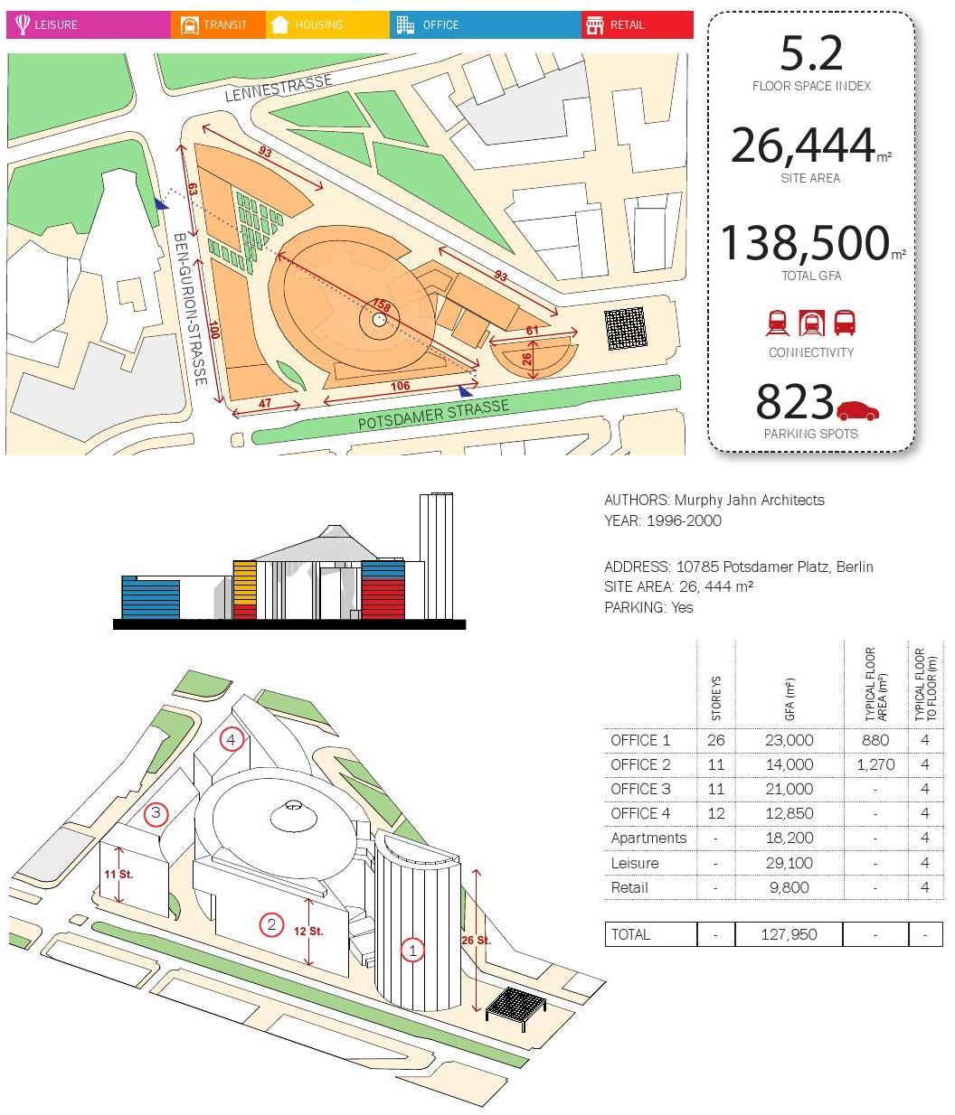
Designed and built by the firm of Murphy Jahn Architects, on behalf of the Corporation which lends its name to the work, the Sony Center occupies an area of approximately 26,500 square meters, the size equivalent to four football fields professionals, and 132,000 square meters construction.
With the exception of the building facing the Potsdamer Platz and reaches higher altitudes, the other seven did not exceed 8 or 10 floors
Spaces
The complex is composed of seven individual buildings with walls shaped like a corrugated iron in the form of interwoven sections and surfaces. In the interior of the building are shared offices, departments, major cinemas in which each year celebrates the Festival “Berlinale”, restaurants, a museum of fine arts and of course the European headquarters of the firm Sony.
• Forum
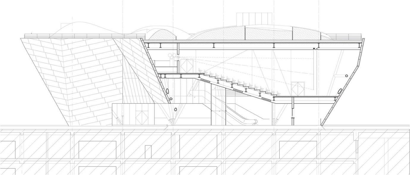
A striking element of this complex is the oval shaped public space that develops in the center of it, the “Forum” or atrium. As public space, it communicates with the surrounding streets through walkways leading to the square occupied by cafes and restaurants, including its famous dome of stretched canvas.
• Tower of Glass
Bahn Tower is the tallest building on the Potsdamer Platz with 103 meters high. This tower with its semi circular glass facade on the full Sony Center on the square and is closer to the east.
• Residential area
The facade of the residential area that opens Bellevuestrasse. It is suspended on a steel bridge, and it highlights the former neo baroque
Project 1 – Thesis Synopsis
61
facade of the former Esplanade Hotel, the only part preserved from before the war.
The residential component in Sony Center is comprised of 60 rental units and 134 condominium apartments.
The rental units range from 38 square meters and the 149, with radiant slab and a spectacular view of the complex and the city.
The 134 condominium units built above the historic former Hotel Esplanade, which creates a fantastic restored entrance lobby to the building. The units range from 62 square meters to 230 meters square.
It wanted to integrate the new planes from the former hotel rooms, as “architectural monument”, but his inability to move them was chosen.
The transfer of one of these rooms, the former kaiser’s camera with a weight of 1,300 tons, was made on a pneumatic mattress that moved 70 meters. In the former kaiser room, a restaurant today.
Two walls of the breakfast room were kept in their original place, but the roof, floor and two walls had to be moved and were placed across the esplanade.
Structure
With a triangular excavation depth of 15.50 meters of the project covers an area of 20,500 square meters.
The mooring structure consisted of the excavation walls diaphragm, whose base is formed by a soft blanket of concrete mulch, at a depth of 30 meters and the installation of 25,000 square meters with 1770 motherboard piles to resist the weight and forces transmitted from the upper levels of the building.
• Cupola
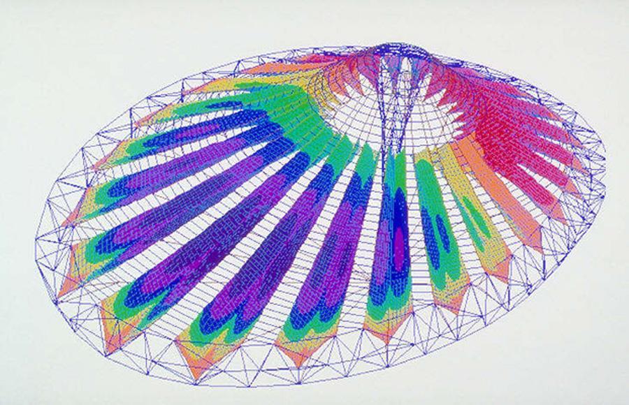
The dome covering the central square is a spectacular piece of engineering, consisting of metal rings that tighten pieces textile membrane, strap shaped,
Project 1 – Thesis Synopsis
62
with a horizontal circular metal structure combined with pieces of laminated glass, which the crown top of the dome
Tensors long cables from the bottom to the center of the dome, and the structure formed by large rings were attached to the buildings that surround it.
It is a prestressed cable structures that create a network of support for a flight out of neck and suspended from a ring in a round beam.
Covered area: 5250 square meters
Length: 102 meters Width: 77 meters
While visually charged lightness, the approximate weight of the structure is 920 tons and is considered the largest of its kind anywhere in the world.
Materials
Steel and glass predominate in all the buildings in the complex, creating an attractive contrast with the characteristic stone buildings in the district of Mitte.
The translucent material of the dome is laminated glass which is combined with webbing fabric allowing the passage of natural light and air circulation.
In the construction of the dome have also used hybrid materials, cables, PTFE coated aluminium and glass, PTFE is a material similar to polyethylene.
Light is an essential part of the overall design as it contracted to the effects of light at the Parisian artist, lighting specialist, Yann Kersalé. Transparency and variety of effects during all times of day make it a patchwork of light and technology with a self produced to save the maximum use of resources.
Roof
It was important to the architect Helmut Jahn that a roof should cover the plaza like an umbrella. The forum was not meant to be sealed, nor should it disconnect users from an outdoor experience.
Project 1 – Thesis Synopsis
63
The exceptional glass membrane roof rests on a ring beam weighing 500t. The alternating application of glass and fabric on a cable structure spans 102m. Structurally, the roof resembles a bicycle wheel in a horizontal position with a hanging central 42m long king post, creating a column free plaza.
Prior to the detailed design of the roof, Arup conducted an environmental study that used wind tunnel tests, dynamic thermal modelling and computational fluid dynamics analysis to assess comfort levels within the Forum space.
The forum roof is unique in its design, urban context, scale and structural use of materials.
Daylight study
Arup performed a daylight study using computer simulations. The Berlin building department needed rigorous technical proof that the plaza roof would meet Germany’s strict daylight requirements for the many offices and apartments that faced the plaza under the roof.
The challenge was to precisely model the complex passage of natural light through the roof and by inter reflection into the offices and apartments. Daylight levels in individual rooms had to be predicted and compared with the code requirements.
Arup met the challenge by applying innovative ray tracing computer techniques to support established daylighting design experience. Our engineers developed a methodology that determined light levels in a few key rooms, from which conclusions could be drawn on the conditions in all other rooms in each building.
A highly detailed 3D computer simulation was built, including the complex geometry of the roof and physically accurate modelling of the transmission and reflection of light from the roof and building facades.
The structural system
A continuous ring beam was placed along the edge of a tilted cut through the hyberbolic cone, resembling the rim in a bicycle wheel.
The two top chords of the triangulated ring beam follow the surface of the hyberbolic cone. The ring beam is elliptical in plan with spans of 102m in the main axis and 78m in the minor axis.
A 42.5m long kingpost was arranged in the tilted axle in the bicycle wheel. Two radial layers of cables connect the top and the bottom of the kingpost
Project 1 – Thesis Synopsis
64
with the ringbeam. The top layer ridge and the valley cables create the folded surface of the roof. The bottom layer of the cables, the kingpost cables, suspends the kingpost over the forum.
The whole system is pre stressed to stabilise the surface created out of cables, fabric and glass. The ring beam is supported vertically at seven points on the top of the roofs of the buildings surrounding the forum. Horizontally, the support configuration is structurally determined to avoid locking any forces from the roof into the buildings or vice versa.
Arup provided structural and environmental engineering, wind tunneling, performed computational fluid dynamic analysis and daylight studies.
65
Project 1 – Thesis Synopsis


66 Project
1 – Thesis Synopsis
67 Project
–
‘
1
Thesis Synopsis
68 Project
–
1
Thesis Synopsis
Net case study
INFOSYS, HYDERABAD
Architect Sundaram Architects Pvt Ltd
Structural Engineer
Nordenson and Associates Designed in 2009 Built in 2015 Site area 64,804.92 sqm Built up Area 24,730 sqm
Location Hyderabad, India
69 Project
1 – Thesis Synopsis
Introduction
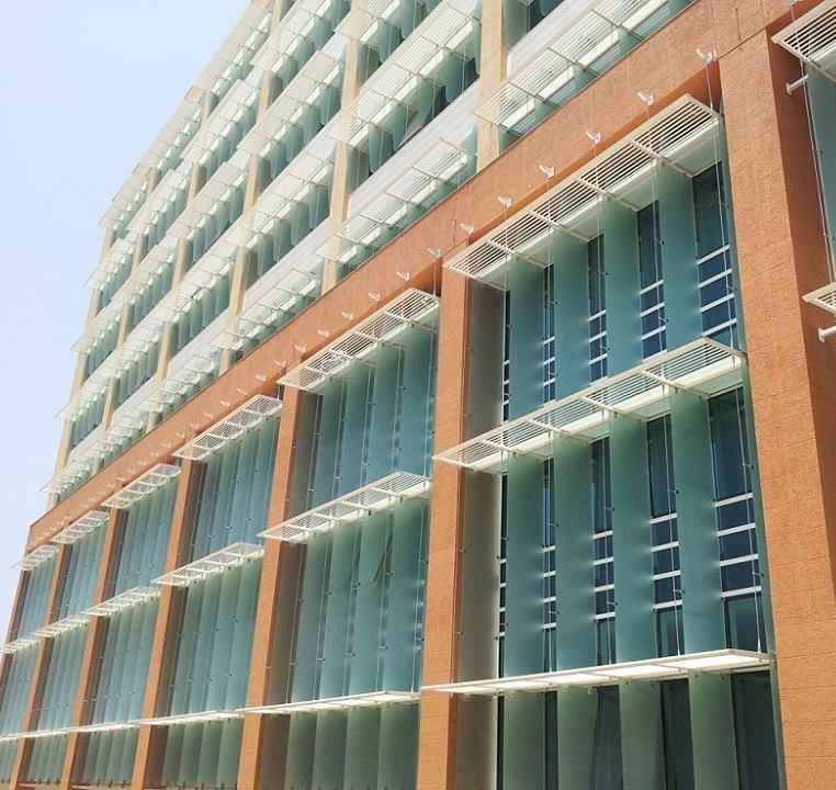
Infosys, a global Consulting and Technology leader, has been awarded the LEED (Leadership in Energy and Environmental Design) India 'Platinum' rating by Indian Green Building Council (IGBC) for its Software Development Block 1 (SDB 1) at its Pocharam campus in Hyderabad, India. LEED Green Building Rating System is a nationally and internationally accepted benchmark for design, construction and operation of high performance green buildings.
The SDB 1 uses the innovative Radiant cooling technology the first in a commercial building in India, setting out higher standards for energy efficiency in building systems design. It has been built keeping in mind a holistic approach to sustainability in five key areas, including sustainable site development, water savings, energy efficiency, materials selection and indoor environmental quality. This is the fourth Infosys building that has won a Platinum rating, taking the total Platinum certified building area at Infosys to over 1 million sq. ft.
Given the high standards in terms of building design achieved at the SDB1 in Hyderabad, it has now been showcased in the 'Best Practices Guide for High Performance Indian Office Buildings' by Lawrence Berkeley National Lab, a U.S. Department of Energy (DoE) National Laboratory. Researchers from Technical University of Braunschweig, Germany have also acknowledged the high energy efficiency and comfort parameters in this building after detailed monitoring and study.
Location
Pocharam, Hyderabad
Area spread over 447 acres, with a seating capacity of 16,000 employees and will be built with a total investment of Rs 1,250 crore.
Building design
Orientation
The longer axis of the building is oriented on the East West axis in order to reduce solar heat gain
Window
Split window with daylight panel (upper glass) and vision panel (lower glass) Wall
70 Project
–
1
Thesis Synopsis
Light shelves in wood panels topped with white reflectors to protect occupants from direct light
Roof
Light coloured ceilings reflect light and reduce the contrast in brightness
WWR
Less than 38%
Daylighting
78.54% of living areas / Daylight hour energy savings: 158 kWh
Artificial Lighting System
Reduced with light shelves, floor planes and reduced WWR
Active Cooling System
Conventional Cooling/ Efficiency: 0.6 KW/TR Radiant Cooling / Efficiency: 0.45 KW/TR Energy consumption for Conventional Cooling: 440000 units/ Radiant Cooling: 269000 units Energy Index for Conventional Cooling: 38.7 kWH/sqm, Radiant Cooling: 25.7 kWH/sqm Radiant Cooling consumes 30% less energy than conventional cooling
Form
form test
Sustainable features
The following strategies were adopted to reduce the impact of the proposed building on natural environment: Sustainable site planning:
• Existing trees were preserved and native trees were planted on site
• Excavation and construction started after the monsoon season to prevent soil erosion and soil runoff from the site
• Top soil was preserved and reused during the construction period for landscaping
• Construction activities were confined to pre designated areas
Project 1 – Thesis Synopsis
71
Reduction in water consumption (compared to GRIHA benchmark):
• Reduction in building water consumption by use of low flow fixtures: 56%
• Water recycled and reused within the complex: 78%
• Reduction in landscape water consumption by planting native species of trees and shrubs and by using efficient irrigation systems: 53%
Passive architectural design strategies adopted in the building:
• The building’s longer axis is oriented on the East West axis in order to reduce solar heat gain
• 78.54% of living areas are day lit and window to wall ratio restricted to less than 38% to reduce solar heat gain inside the building
• Natural ventilation induced in the building
Reduction in energy consumption (compared to GRIHA benchmark) while maintaining occupant comfort:
• For achieving visual comfort
Energy efficient artificial lighting design is compliant with ECBC recommendations
Occupancy sensors in rooms to reduce energy consumption
External shading and efficient glazing to reduce solar heat gain and have glare free daylight have been installed
• For achieving thermal comfort
Building envelope is ECBC compliant, which helps reduce cooling loads in AC spaces and meets thermal comfort levels in non AC spaces
Radiant cooling technology has been installed
External shading and light shelves to cut glare and reduce solar heat gain
Project 1 – Thesis Synopsis
72
Renewable energy technologies installed on site:
• Installed capacity of Solar energy: 44 KWp
Use of low energy/green materials:
• Use of ceramic tiles and carpets with recycled content
• Use of low energy material for internal partitions, panelling, false ceiling, and in built furniture
Key features of this Platinum rated building include:
Water Efficiency: A 48% reduction in overall water consumption has been achieved in the building through the use of efficient plumbing fixtures and by water recycling. 100% of waste water from the campus will be treated on site, helping in the reduction of potable water consumption.
Energy Efficiency: The building is 40% more efficient than the globally accepted ASHRAE standard. This has been achieved through an efficient building envelope including high performance glazing and adequate shading, radiant cooling system, efficient chillers, pumps and fans, efficient lighting system and smart building automation.
Day lighting: Over 90% of the office space has natural light, reducing the need for artificial lighting during daytime. The design includes light shelves along all windows to ensure that the natural light travels as deep into the building as possible.
Efficient Material Selection and Management: Recycled materials account for 18% of the total value of materials in the building; these include aluminum, glass, steel, plywood and tiles among others. 38% of the total project material by cost was manufactured regionally thereby reducing pollution due to transportation.
Air conditioned area: 17,338 sqm
Non Air conditioned area: 7,392 sqm
Energy consumption reduction: 56% reduction from GRIHA benchmark
73
Project 1 – Thesis Synopsis
Water consumption reduction: 56% reduction from GRIHA benchmark
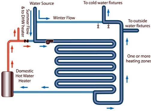
EPI : 51.85 kWh/Sqm/year
Occupancy hours : 8.5 hrs/day
Renewable energy installed on site : 44 KWp
GRIHA rating : 5 Stars
Project 1 – Thesis Synopsis
74
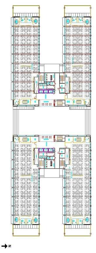
75 Project
–
1
Thesis Synopsis
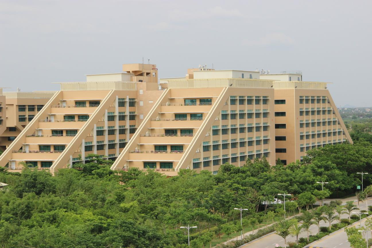
76 Project
–
1
Thesis Synopsis
THE CAPITAL BUILDING, MUMBAI
Live case study
Architect Ar. James Law Designed in 2008 Built in 2012 Built up Area 93000 sqft Location BKC, Mumbai
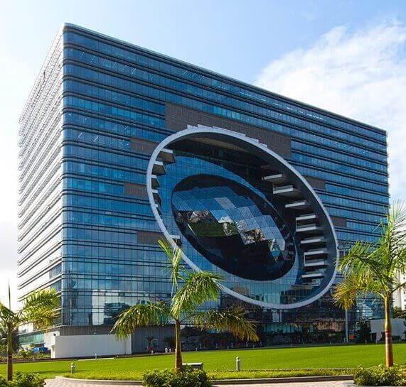
77 Project
–
1
Thesis Synopsis
Introduction
The huge structural steel frame with diamond shaped, and green plants flanking outdoor terraces, guarantees a unique look on its facade, offering a fantastic view of the region of Mumbai. With its bold and innovative structure, “The Capital” deliberately reveals his calm, attractive and elegance. This is an extremely difficult task to develop a concept of revolutionary design for an office building with AAA rating which in turn achieves over 80% efficiency simultaneously. The building earned the LEED Gold Certification for its core and shell, together with the system for collecting rainwater.
Location
The Capital is one of the most recent projects of the architect, is part of Bandra Kurla Complex (BKC), new financial center of the city, in the suburban areas of Bandra and Kurla, in South Bombay. With a number of offices made on a commercial podium of retail stores, the complex is a slender tower with sinuous lines and an interesting and different profile within the environment of Bombay (Mumbai), the most populous city in the India Bombay, named locally Mumbai (pronounced / mʊmbaɪ /; Marathi: मुंबई, Mumbai, AFI: mʊmbaɪ), is the capital of the federal state of Maharashtra in India. In Spanish, the use of the name Bombay is still very common and some impartial journalistic style and the Royal Spanish Academy, recommend to continue using it, since the change of the official name affects local languages but not Spanish exonyms.
Concept
Comprehensive sustainable concept of form and function have inspired the design of the building and its urban context as never before in India.
Cybertecture
The “Cybertecture” is the ultimate expression of innovative art married with functional needs, taking into consideration the environment and humanity.
This is the philosophy of the architect James Law, a combination of innovation and technology with the urban fabric of a conscious and environmentally sustainable manner.
78 Project 1 – Thesis Synopsis
The purpose of Law is the creation of high tech buildings that are healthy and ecologically balanced environment to live, lock or play.
Spaces
Located in the heart of BKC, new financial nerve center of Mumbai, The Capital is a development that has become iconic, a building that has a cutting edge and contemporary facade eternal, while the interiors have a rich color palette and textures.
Built to the innovative idea of Cybertecture fuses modern architectural and technological concepts to create something extremely marked and imaginative. From the top of a valley architectural modeling, the financial center welcomes visitors with an atrium that rises 10 levels and ends up falling in the large lobby of 743m2, with 3 height levels featuring cafés, bars and high end restaurants or other more affordable, while “egg” of the facade, as well as becoming an idiosyncratic symbol of progress, offers a magnificent view of the park and city.
MediaticFacade
The large oval shape in front of the building, not only serves to identify it as a construction out of the ordinary, but inside has a large LED screen media communication providing shade which hangs inward while news projected that the public is on the outside.
The entrance lobby is defined with a large green canopy that increases the only aspect of the building. The green garden is developed throughout the building with natural indoor waterfalls that help to cool the air.
The Capital has art systems and facilities such as automated parking, a gym, spacious and modern toilets on all floors and equipped offices more high tech devices, with varying surfaces and adapted to the requirements of customers.
SmartParking
One innovation in the design of the building is the smart parking system. Using internet and a card system, occupants can enter the system and order your car from the office to have it in the door and shorten waiting time. The parking lot for 700 vehicles.
Structure
79 Project
–
1
Thesis Synopsis
The main materials used in the super structure are reinforced concrete, steel and reinforced glass.
The buildings which designs James Law are smarts, efficient and make their contribution to the planet. The extensive use of computer simulations has an important role to play in the design of these buildings, able to withstand the challenges that are faced. The Mirror Cybertecture and Cybertecture Nodal Points are some of the significant innovations of the architect.
Integrating technology enables energy efficient buildings, which change as they change vital parameters of the building to adapt to real time data.
Enclosure
There are three main features in the building envelope.
Stepped facade
On the west elevation amazing tiered green facade and glass is created. The facade is stepped while each floor is supported by columns and cantilevers whose features make the building itself acts as a shading device.
Egg
An egg shaped structure is the masterpiece that is inscribed inside the lobby to the sky (sky lobby) on the east elevation, natural waterfalls and greenery on both sides that enhance the cooling effect of the atrium. Bright LED stripes on the facade projecting not only act as a multimedia device, but also play a role sunscreen.
Coating
Systems adopting internal and external coating PVDF which is easily maintained and are resistant to UV rays.
Materials
The 18 floors of the building were made with high technology, setting new standards for sustainable office buildings thanks to the striking elliptical element in its glass facade. It is equipped with modern surveillance systems and intelligent integrated throughout the building. Its design ensures reduced costs lifecycle and improves staff productivity.
80
Project 1 – Thesis Synopsis
The innovative design of the building’s skin, with integrated intelligent environmental technologies and high isolation dual front transparent glass optimizes the overall energy efficiency by approximately 80 % compared to conventional office buildings, due to the maximum simultaneous use of daylight, fresh optimized air management and treatment of wastewater and stormwater sewer without creating.
PVDF coating on the outside glazing minimizes UV and make the front easier to maintain, while the ceiling diffusers reflect natural light in the atrium reaching the lowest level of the podium, reducing demand for lighting.
A point in the atrium cooling reduces the cooling load, while opening windows in the offices promote natural ventilation. Natural waterfalls and greenery in the atrium also help improve the natural cooling effect.
Health services equipped with innovative technology GROHE offer the highest level of sustainability, efficiency and design on each floor.
The building has 16 high speed elevators and two service, equipped with a Compass System to optimize the waiting time considering the active traffic at all times.
81 Project
1 – Thesis Synopsis
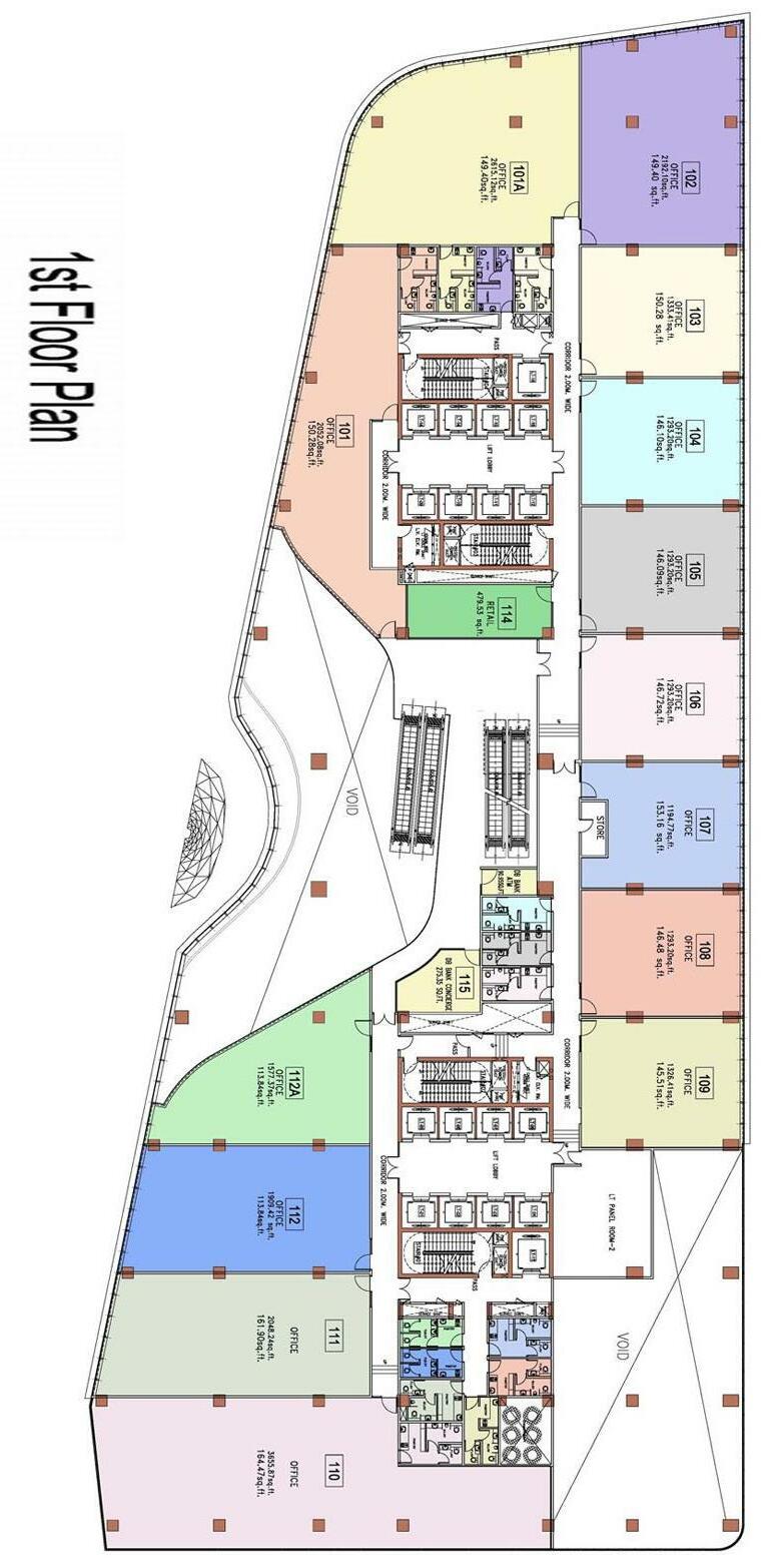
82 Project
–
1
Thesis Synopsis
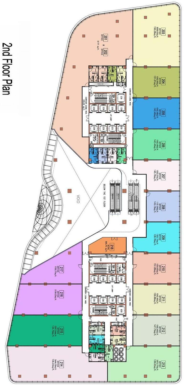
83 Project
1 – Thesis Synopsis
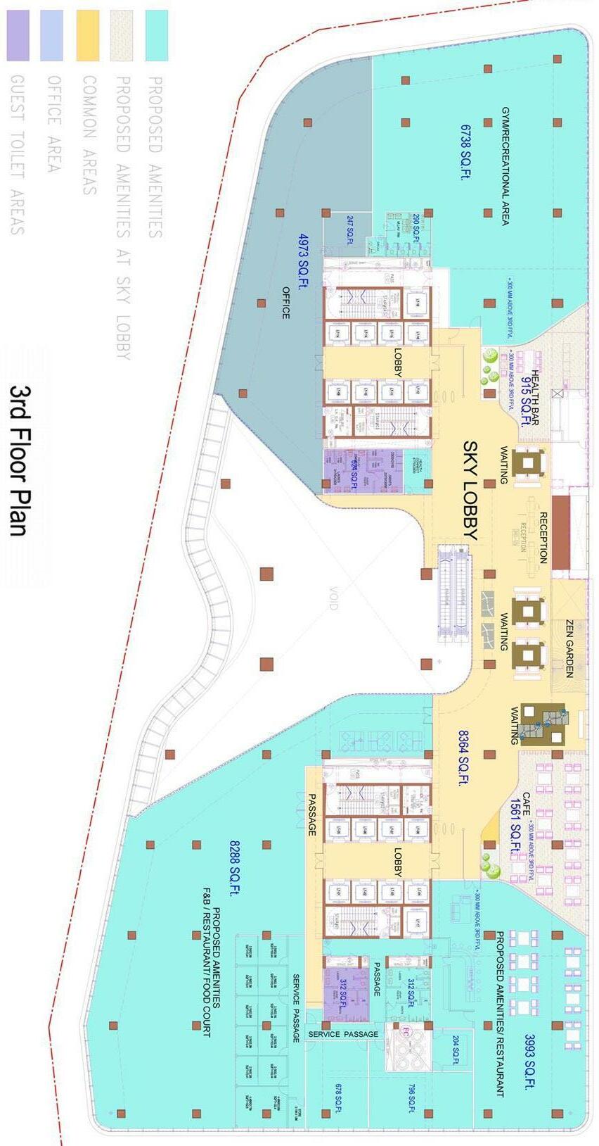
84
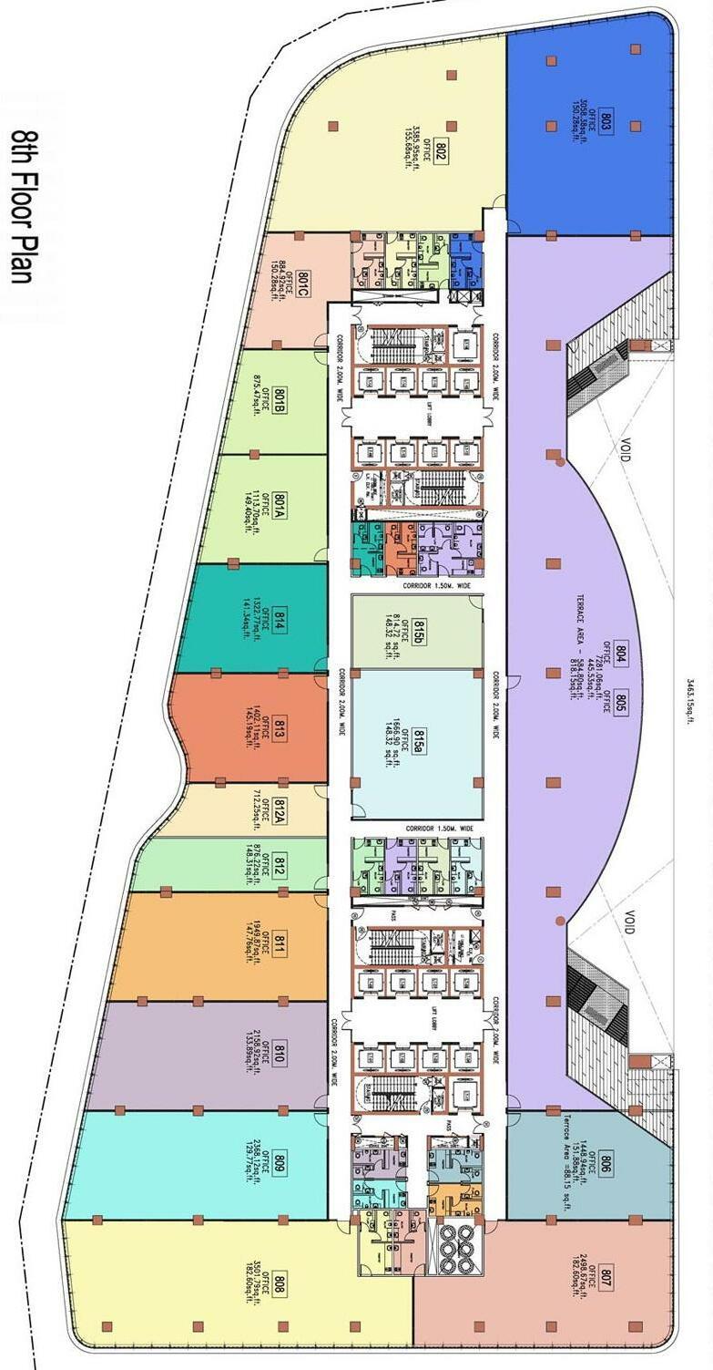
85 Project
1 – Thesis Synopsis
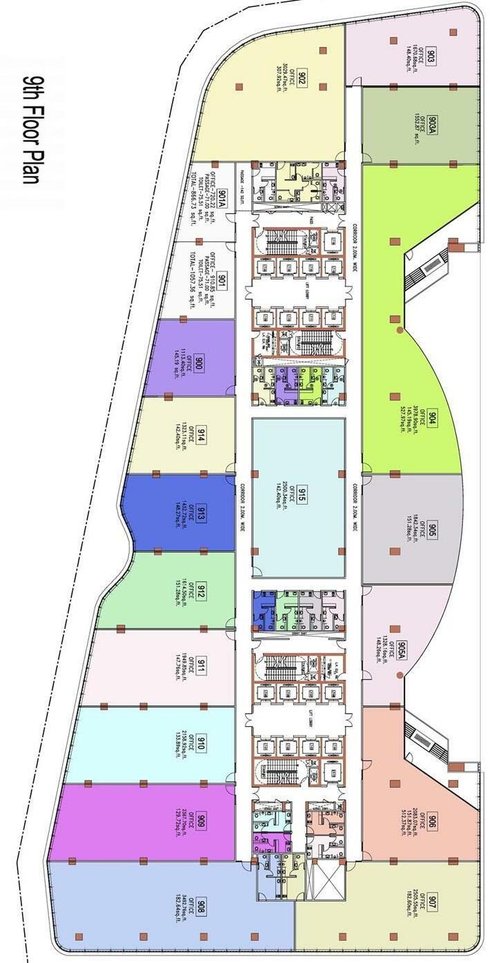
86
Project 1 – Thesis Synopsis
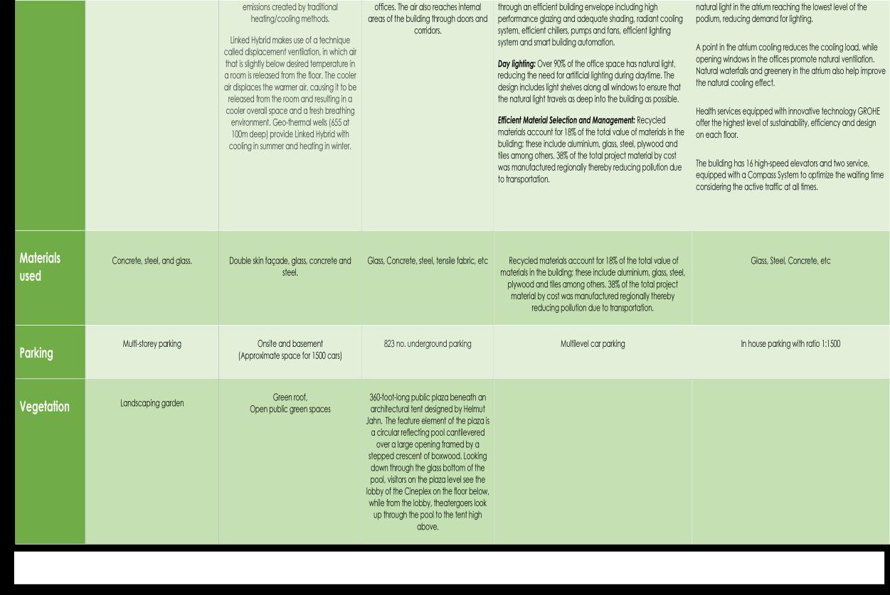

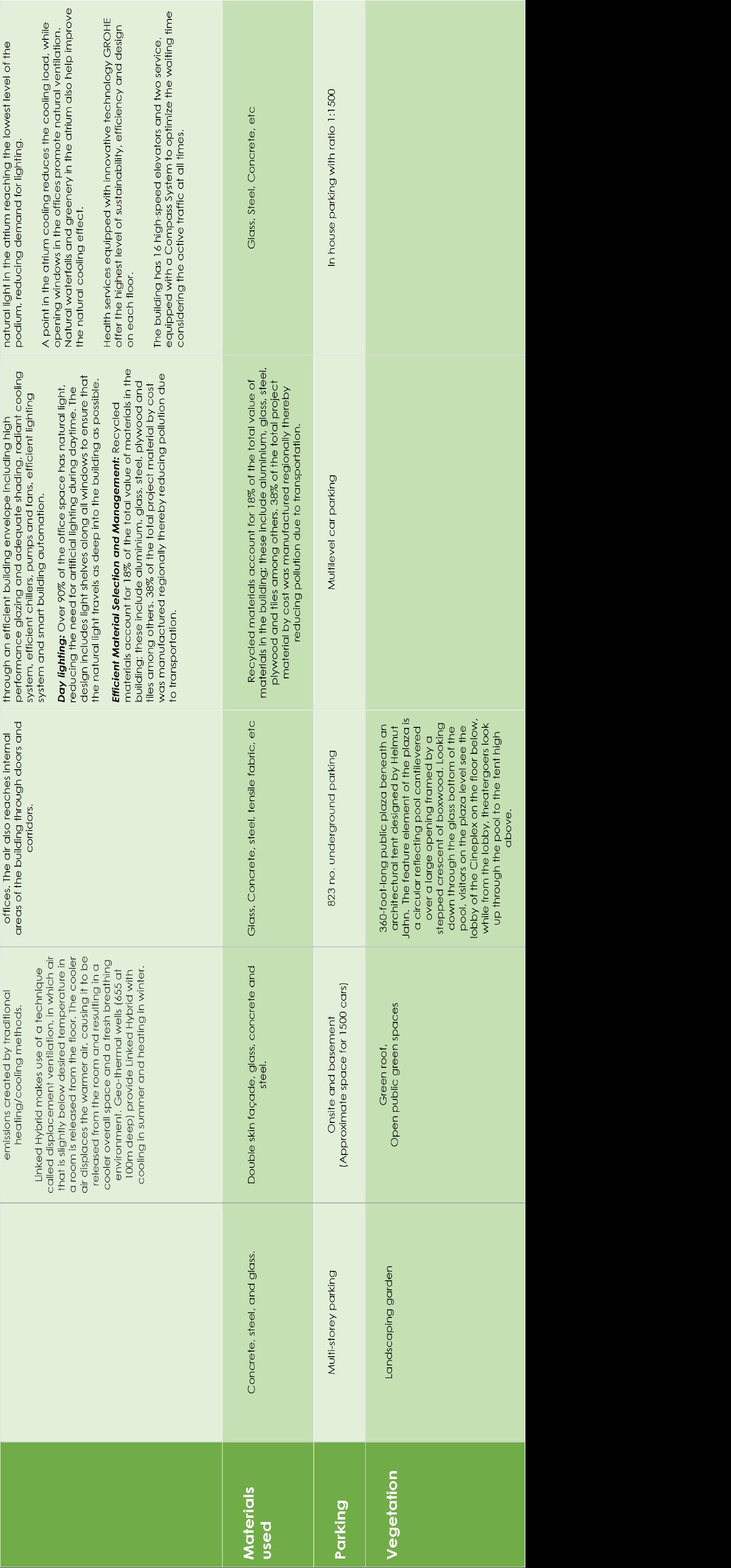
CHAPTER IV
SITE ANALYSIS
89 Project 1 – Thesis Synopsis
Criteria for site selection
'Scarcity of land in fast growing city.
Rapid growth of population in urban communities therefore constant pressure of the limited land area affected the evolution of building.
Horizontal development gets restricted due to less space & then vertical growth is the ultimate option available.
Restriction of random expansion in major cities adjacent to agriculture land. Innovation in structural system.
Expensive land process.
The high cost of setting up infrastructure for new cities.
Site selection
Why India?
India, officially the Republic of India is a country in South Asia. It is the seventh largest country by area, the second most populous country with over 1.2 billion people, and the most populous democracy in the world. India is a federal constitutional republic governed under a parliamentary system consisting of 29 states and 7 union territories.
Why Maharashtra?
The state of Maharashtra is the second highest populated state of India. These people have origin from different communities and religion. The identity of Maharashtra as a culturally diverse state is because of such differences. Diversity in the culture because of the geographical presentation and historical values of the state. Some of the oldest known religions of the country have their existence in the state.
90 Project 1 – Thesis Synopsis
Why Mumbai?
Mumbai, the capital of Maharashtra, has a land area of 603.4 km². It has a population of about 21.64 million for Mumbai. The population in Mumbai is growing at a rate of 1.13% per annum which is greater than the national growth rate of 1.08%. Most cities in the developing countries are urbanizing at a very fast rate. India Statistical Service states that “The country is urbanizing at an increasing rate By 2025, the overall India’s population is expected to reach approximately 1.396 billion of that number, Mumbai is projected to increase from approximately 26.38 million. With a population density of 21,000 per km², and a growth rate of 1.13% per annum, Mumbai has highest density, compared to other cities with similar geographic and economic characteristics like Delhi, Tokyo, Shanghai and New York.
From the comparative analysis of the three cities; Mumbai, Tokyo, Shanghai, New York and Delhi it can be deduced that Mumbai has a highest population density. Mumbai suffers serious congestion (human and vehicular), urban sprawl, housing shortages, sanitation and infrastructural problems. If Mumbai is to accommodate this increased population it must have a comprehensive and long term plan to manage the population growth and the accompanying strain on city services including housing, infrastructure, education and health to name a few.

91 Project
–
1
Thesis Synopsis
Mumbai’s urban problem of human and vehicular congestion, pollution, environmental degradation and infrastructural inadequacies is not due to overpopulation but inappropriate planning as stated earlier.
There can be two approaches or schools of thought to these urban issues.
1. Direction of traffic (human and vehicular) out of Mumbai, through the creation of sustainable Satellite Towns. An example of this is the city of Navi Mumbai, South of Mumbai.
2. Densification of Mumbai through,
urban re planning and structuring.
Multi Storey Structures to satisfy area requirement.
Mixed used building and development.
Why Bandra Kurla Complex?
The Bandra Kurla Complex is a planned commercial complex in the suburbs of the Indian city of Mumbai. It is expected to de congest southern Mumbai and seed new areas of planned commercial real estate in the metro politan region.
About Bandra Kurla Complex
Bandra Kurla Complex is the premier preferred Central Business District, in India. The land is the most valuable real estate of Mumbai. The goal was to enhance the area to create a vibrant and pleasant CBD in the very heart of Mumbai where people would return, to conduct business, to work and to entertain. Also the proposal of Google campus with the leased land area of 1 lakh sqft.
1 – Thesis Synopsis
92
Project
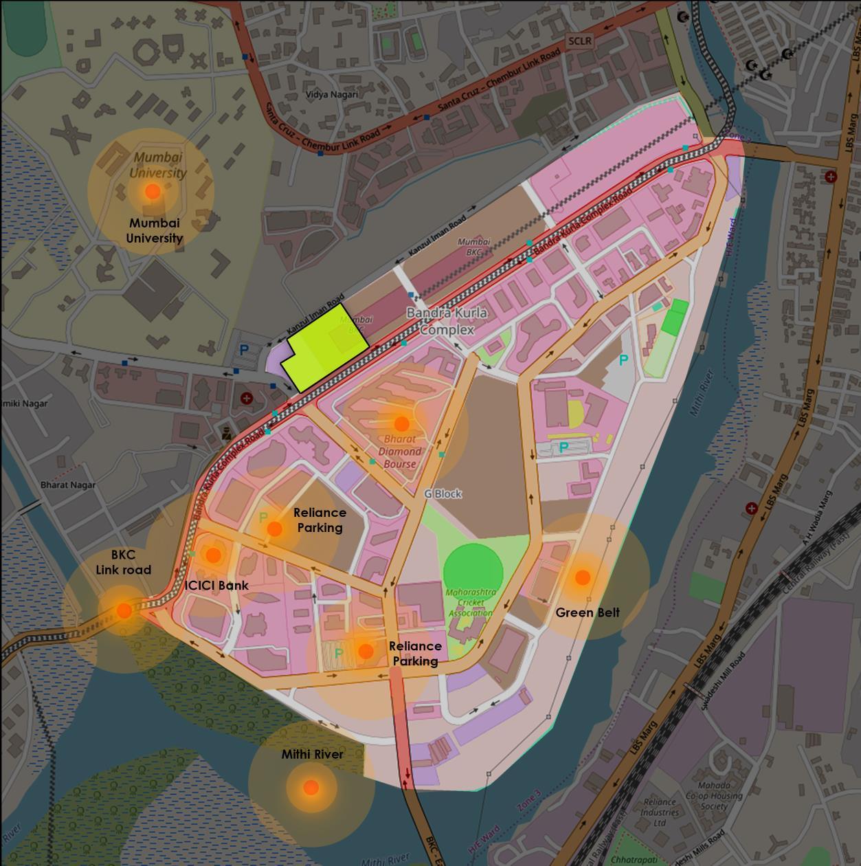
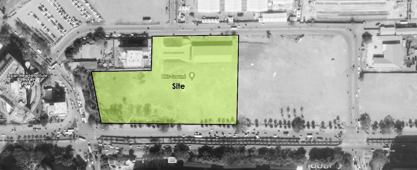
93 Project
1 – Thesis Synopsis
Location
Site is Located in G block of Bandra Kurla complex the international finance & busi ness centre of Mumbai. Mumbai is located on the western seacoast of India on the Arabian Sea at 18°53" N to 19° 16" N latitude and 72° E to 72°59' E longitude.
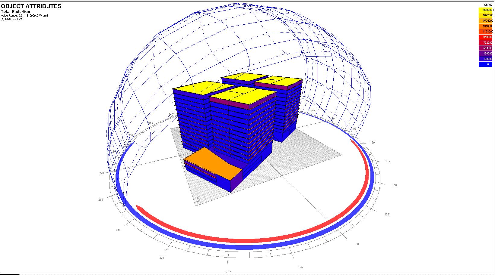
From these lands, the MMRDA was aiming to generate a revenue of Rs 3,000 crore, which was supposed to be used in big infrastructure projects, like Metro corridors, IT’s or . The MMRDA has reserved a rate of Rs 3.44 lakh per sq m on built up area.
Legal information
Ownership MMRDA
Future urban development According to DCR the site is proposed for IFSC commercial use.
Geography
The city The city of Mumbai is situated on India's west coast, on the Arabian Sea, roughly 500 km south of the Tropic of Cancer. Originally, the city
94 Project
1 – Thesis Synopsis
rested upon seven small islands. These islands are now connected to one another by reclaimed land.
Climatic conditions
The Climate of Mumbai is a tropical wet and dry climate. Climate can be best described as moderately hot with high level of humidity. Its coastal nature and tropical location ensures temperatures won't fluctuate much throughout the year.
Temperature
The mean maximum average temperatures in about 32 °C in summer and 30 °C in winter, while the average minimums are 25 °C in summer and 20.5 °C in winter.
Rainfall
Average rainfall is 242.2 cm (95.35 inches).
Project 1 – Thesis Synopsis

95
Humidity

The relative humidity typically ranges from 33% (comfortable) to 95% (very humid) over the course of the year, rarely dropping below 20% (dry) and reaching as high as 100% (very humid).
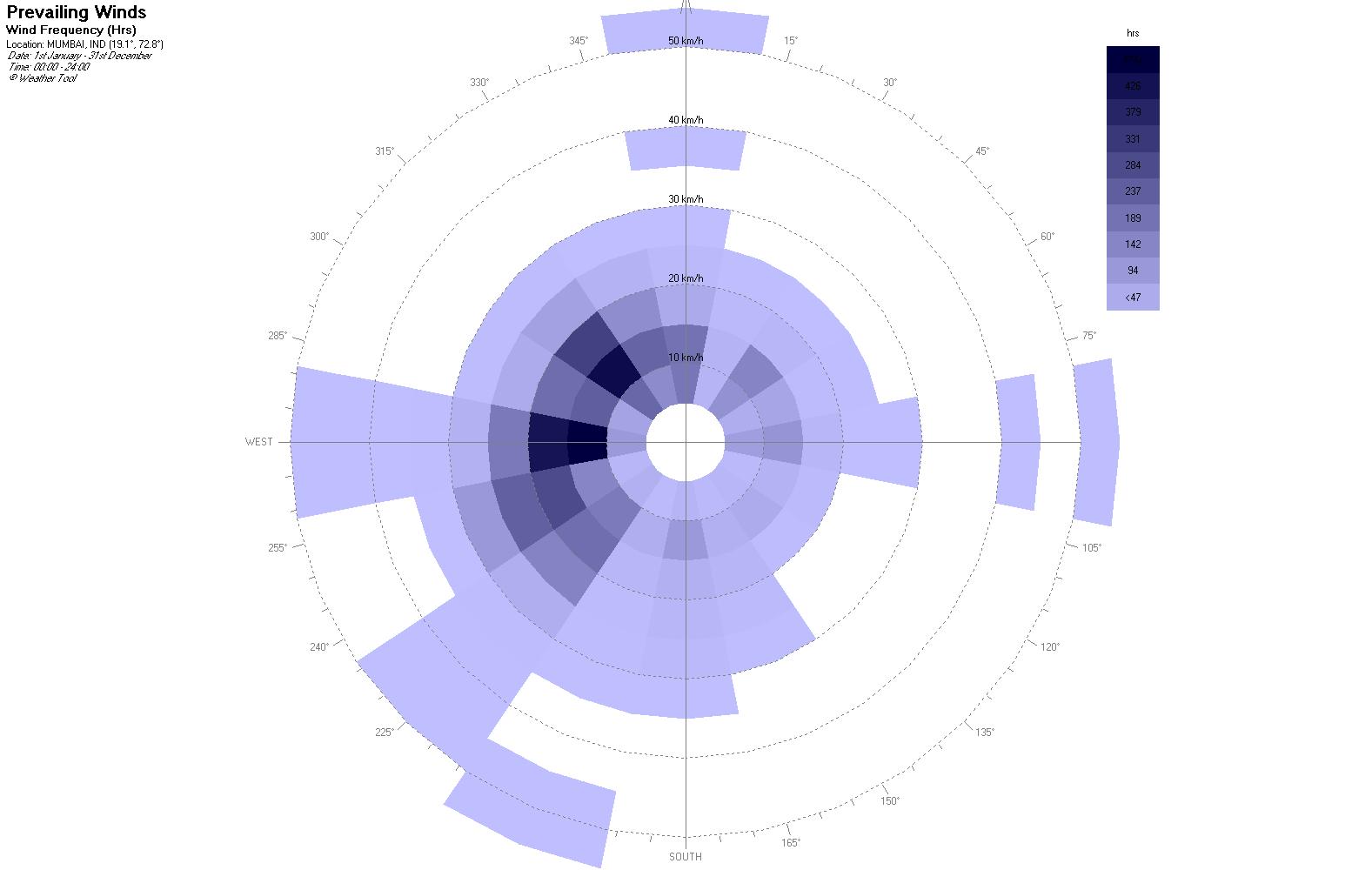
96 Project 1 – Thesis Synopsis
Wind direction
The wind is most often out of the west (36% of the time),North west (20%), south west (13% of the time), and north west (11% of the time). The wind is least often out of the south east (3% of the time), south (4% of the time), and north (5% of the time). Wind Directions over the Entire Year.
Population
Population of Mumbai in 2011 is 12,442,373; of which male and female art 6,715,931 and 5,726,442 respectively. Al though Mumbai city has population of 12,442,373; its urban metropolitan population is 18,394,912 of which 9,872,271 are males and 8,522.641 are females.
Economy
Mumbai is India's largest city (by population) and is the financial and commercial capital of the country as it generates 6.16% of the total GDP.
Land use
About 42% of the land area of the plan is earmarked for commercial use and 14 per cent for housing. One of the important features of the area is preservation of large open spaces surrounding various public centres.
Neighbourhood Context
Modem iconic Contemporary buildings are surrounded to the site. Maximum glass facade is used with modem techniques in construction. Innovation in structural system. Site is surrounded by commercial building. BKC houses a number of commercial buildings including Jammu & Kashmir Bank National Business Centre, National Stock Exchange, SEBI, NABARD Head Office, IL&FS, Asian Heart Institute, Dow Chemicals, ICICI Bank, Ci tibank, Dena Bank, Bank of Baroda, State Bank of India, Bank of India, Bharat Diamond Bourse, It also is home to the Mumbai Cricket Association's cricket ground and the United States Mumbai Consulate.
97 Project
–
1
Thesis Synopsis
Zoning and size
The site is located in the G block of Bandra Kurla complex, surrounded by roads on both the front and back side with road width of 45 m and 24m respectively. Total site area is 26,720 sqm with an FSI of 4 for commercial and 3 for residential. According to MMRDA building regulations the setback requirenments are 15m on front and 12m on the rear side.
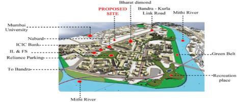
Accessibility
Worli Sea link 5.8 kms.
Chhatrapati Shivaji International Airport 12.00 kms
Western Express Highway 3.00kms
Eastern Express Highway 9.30kms
Railway Station Sandra Marshall Railway station 1.00kms. Sandra Railway Station 1.00km Sandra Terminus Railway Station I.00km Khar rail way station 2.00km.
Vegetation
98 Project 1 – Thesis Synopsis
South side has vegetation along with 45.00 m wide road side. the 3.00 m pathway adjacent to the road is shaded with the tree from both side . Height of the trees are 4.00m to 6.00m. Creating shades on pathways as well as road side parking.
Soil type
The soil type is marshy land
Drainage
In 1977, the MMRDA was appointed as the Special Planning Authority for planning and development of this complex. It covers 370 ha. area of once low lying land on either side of the Mithi River, Vakola Nalla and Mahim Creek. The area had poor surface drainage and was severely affected by pollution in the Mahim Creek. The channelization of 6.0 Km of the length of the Mithi River from Mahim causeway to CST Road Bridge and its tributary Vakolla Nalla was undertaken since 1980's to improve water carrying capacity and reduce pollution. Following the floods of 2005, further widening and deepening took place along with improvement of bed gradient.
Site justification
Bandra Kurla Complex is a planned business district in Bandra, India. It is the most prominent commercial hub in Maharashtra after Mumbai's Nariman Point and Cuffe Parade
According to MMRDA, the complex is the first of a series of "growth centres" created to "arrest further concentration" of offices and commercial activities in South Mumbai.
BKC has aided to decongest the CBD in South Mumbai while seeding new areas of planned commercial real estate in the metropolitan region.
Site is surrounded by major activity areas like public transport & commercial areas.
Site is selected such that it has visual connectivity from the adjacent major street, economic
growth is more.
Best suited for business setup or expansion.
Well connected to airport and railway stations.
Project 1 – Thesis Synopsis
99
BKC Project features
Bandra Kurla Complex (BKC) is one of the key areas for which MMRDA is the "Special Planning Authority". Today, the complex enjoys a status that is similar to that of Nariman Point. The complex is already providing more than two lakh jobs and is a perfect solution to absorb future growth of offices and commercial activities successfully. The complex has showcased tremendous growth in the changing times and the development of 'E' block is noteworthy.
The Authority has developed 19 hectares of land with the presence of prominent institutions such as the Reserve Bank of India, Income Tax, Sales Tax, Provident Fund and many other corporate and commercial establishments. Together, these buildings offer an office space as large as 1,17,000 sq. mtrs., potential enough to accommodate thousands of jobs. This meticulously planned complex also showcases a City Park which is regularly thronged with people.
Currently, the BKC also hosts 30 kilometres cycle track and corporate headquarters of MNCs. Several companies operate from BKC. The complex has staff quarters, club, 5 Star Hotels, Convention Complex, Diamond Bourse and hospitals apart from offices.
Geography
The Mumbai Metropolitan Region lies to the west of the Sahyadri hill range and is part of the North Konkan region. It broadly lies between the rivers Tansa in the north and Patalganga in the south. The south western boundary extends beyond the Patalganga River and includes the town of Alibag and Pen, thus including parts of the Tehsils of Alibag and Pen. On the west, the MMR is bounded by the Arabian Sea; on the south east, it extends to the foothills of the Sahyadris and in the north east, its extent is contiguous with the administrative boundaries of Bhiwandi, Kalyan and Ambernath Tehsils. The geography of the region is a significant determinant of urbanization in MMR. The MMR is largely a low land, though not plain. A series of north south trending
100 Project
1 – Thesis Synopsis
hill ridges bring significant local elevational variation; though the average elevation of most areas is below 100 metres above sea level (refer Map no. 3). The significant geographical features of the region include hills, rivers, lowlands and a long coastline, which in turn determine the nature of land uses prevalent in the region. The MMR is typical of the Deccan Basaltic terrain with flat topped mountains bordering a low lying coastal region traversed by five rivers. The above features are described briefly as under:
a. Hills: These include the Matheran Ridge, the Panvel Mumbra Ridge, the Bhiwandi Gotara Ridge, the Bhatsai Hills, the Tungar Hills complex, the Kanheri Ridge, the Trombay Hills, the Uttan Hills, the Karnala Hill Ridge, the Kankeshwar and the Bhal Man hills;
b. Rivers: MMR is a water resource rich region fed by five rivers and a network of creeks and tributaries. The major rivers that flow within the MMR are the 135 km long Ulhas river and its tributaries, the Bhatsai and Kalu, all of which flow towards the western coast. Other rivers include the Tansa and Vaitarna which flow in the North and the Patalganga, Panvel, Balganga, Bhogeshwari, Amba and Bhogwati rivers in the South. All these rivers ultimately drain into the Arabian Sea through a number of creeks. The Vaitarna and Tansa rivers drain out through the Vaitarna creek; the Ulhas River drains out through the Vasai and Thane creeks; the Patalganga, Balganga and Bhogeshwari, and Amba rivers drain through the Dharamtar creek while the Panvel River drains out through the Panvel creek.
c. Lowlands: These include the Patalganga valley, the upper Ulhas valley, the eastern lowlands that lie between the Bhatsai in north and Ulhas in south, the lower Ulhas valley or the Kalyan basin, the Vasai lowlands, the Bhiwandi lowlands, the Salsette lowlands, the Thane creek lowlands, the Uran lowlands or the Patalganga estuary and the Mumbai islands.
d. Coastline: The MMR has a long coastline of nearly 270 km which is punctuated by several creeks, of which the Thane, Panvel, Versova, Manori and Vasai creeks are the larger ones. Several large bays and sandy beaches are also present along the coast between the creeks and jutting headlands. The northern coastal belt between Vasai and Arnala is marked by beautiful beaches and horticultural plantations while the southern coastal belt between Rewas and Alibag is scenic with beaches, palm groves and paddy fields. The Gorai and Juhu beaches in Salsette and the Dadar and Chowpatty beaches
101 Project
1 – Thesis Synopsis
in Mumbai Island are the main beaches in the region. Backbay and Mahim bay are significant bays in Greater Mumbai. The coast is also marked by the presence of several off shore islands, of which Karanja Island, Butcher Island and Elephanta (Gharapuri) Island are the major ones. Greater Mumbai’s Salsette and Mumbai Island were also formed as a result of silting and reclamation of seven smaller original islands over the last few centuries. The lowlands between the hills have historically been used for paddy cultivation, except for the coastal areas which were marshy with salt pans while the hills have forest cover.
Geology and Soils
a. Soils: Basaltic lava flows of the upper Cretaceous to the lower Eocene age underlie most of MMR, which largely falls in the Deccan lava country. Shallow alluvium formations of recent age occur as narrow stretches along the major rivers in the region. Soils in MMR are largely derived from Deccan Trap or basalt, which is volcanic in origin. They are of two types medium to deep black and reddish in colour. The basaltic flows are horizontally bedded forming step like terraces and are more or less uniform. The soil in Mumbai is slightly different from the rest of MMR and the types of rocks found here include various types of basalts, rhyolites, trachytes, volcanic breccias, ash beds, diorites and inter trappean beds. The Thane area is largely made up of basalt volcanic breccias and tachytylic basalts, intruded by numerous basaltic and doleritic dykes. The southern parts of MMR, viz. Panvel, Uran, Pen Khopoli, is dominated by both compact and amygdaloidal basalt, which are intruded by a number of dykes and some areas have the presence of soil overburden of 5 to 8 m depth.
b. Minerals: There are no minerals of economic importance in the region with the exception of bauxite deposits in Tungar hill ranges. The basalt found in the region is a good construction material that can be used for a variety of purposes including masonry, roadworks or concrete aggregate. Fine grained trachytes, brownish pink or greenish in colour, found only around Mumbai (Malad, Uttan, Dongri) are used extensively for building material. Quarrying activity on an extensive scale is witnessed currently in the region, especially in Thane district.
c. Geological Features: The following important geological features are observed in the region: i) The hot springs in northern MMR at Vajreshwari, Akloli
102 Project
1 – Thesis Synopsis
and Ganeshpuri. The waters are largely saline containing sodium, calcium, chloride and sulphates, and the temperature ranges between 42 55 degrees Celsius, ii) The hexagonal basaltic columns at Gilbert Hill in Andheri, Greater Mumbai, of about 27 metres height, iii) The pillow lavas at Sewri, iv) The frog beds (intra trappean beds of scientific value) at Worli hills, Greater Mumbai, which give clues regarding the age of the Deccan traps v) The raised beaches of Manori, which indicate vertical movement of continents or the recession of oceanic waters.
d. Seismic Activity: MMR lies in a seismically active zone classified Zone III, which means that an earthquake of up to magnitude 6.5 on the Richter scale may be expected. The Deccan area was largely believed to be an earthquake free zone until the major Koyna earthquake of 1967 occurred. Since then, the region has experienced several quakes at regular intervals.
Climate
The climate of MMR can be described as warm and humid. MMR receives ample rainfall from the south western monsoons during the wet monsoon season between June and September every year. The annual rainfall ranges between 180 cm 248 cm. The monsoons are followed by three short cooler winter months between December and February. The rest of the months are hot.
Temperature: Typically, January is the coldest month of the year with May being the warmest, in accordance with the course of the sun. During the monsoons, the temperature is nearly uniform at around 27 degrees Celsius. In October, the temperature rises before beginning to fall gradually reaching its minimum in January.
Wind: The normal seasonal prevailing wind direction during the dry season is west north west except during the monsoons when it is south west. During December, the wind direction fluctuates between west north west and east north east. There is considerable diurnal and seasonal variation though there is little fluctuation in the velocity in the dry season. The winds are light and variable at 8 kmph during the dry season and reach a peak of around 13 kmph during the monsoon. Southern parts of MMR have higher wind velocities at around 10 kmph during the dry season peaking to about 25 kmph during the
1 – Thesis Synopsis
103
Project
wet season. Squalls are common during the monsoon and accompanied by gusty winds.
Monsoons: The south western monsoons generally arrive in the Mumbai area during the second week of June and continue till late September. The average rainfall in the region is over 2000 mm, with the coastal areas receiving much less rain than the interior plains typically, though they receive the first onslaught of the rains. Due to local topographical conditions, Matheran which is situated at 760 m above MSL receives the highest rainfall in the region.
Climate Variation: Though typically the climate of Mumbai and its surrounds are termed as equable with no large seasonal fluctuations of temperature, (due to the proximity to the sea and the relatively large amount of humidity in the atmosphere), over the years, however, with increasing urbanization, there are variations in the climate. Studies in the long term trends of rainfall reveal a significant increase in monsoon rains for Mumbai between 1901 2000, significant reduction in wind speeds (59 per cent) along with significant changes in frequencies of occurrence of warmer days (maximum temperatures above certain threshold) and colder days (minimum temperatures below certain threshold).
1 – Thesis Synopsis
104
Project
CHAPTER V
DESIGN DEVELOPMENT
105 Project 1 – Thesis Synopsis
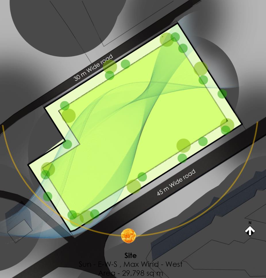
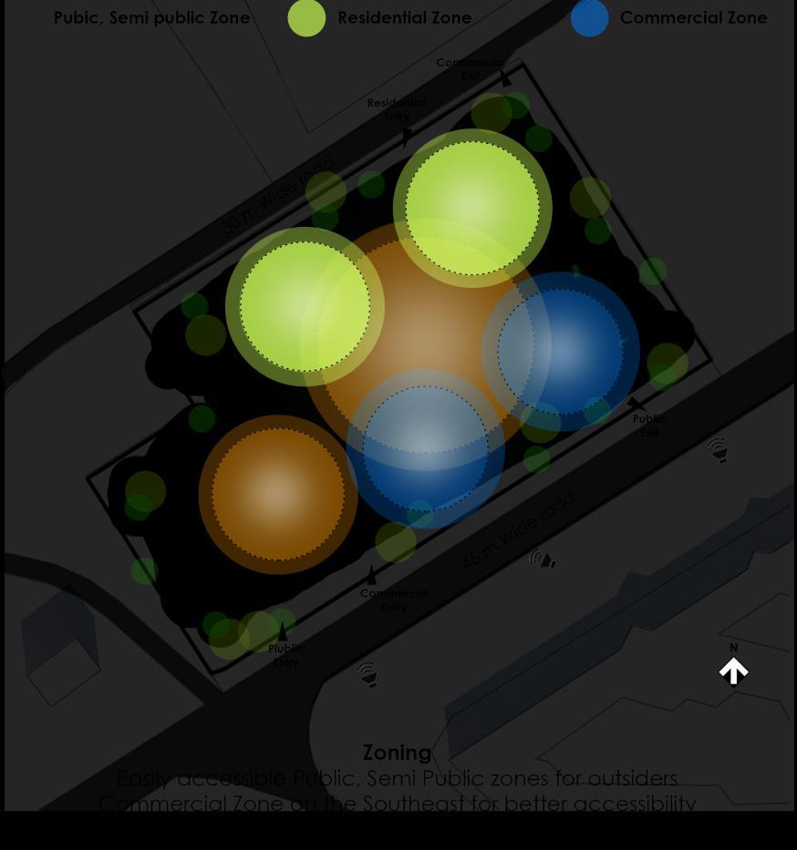
106 Project
1 – Thesis Synopsis
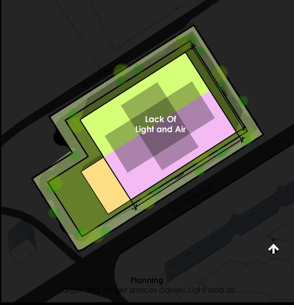
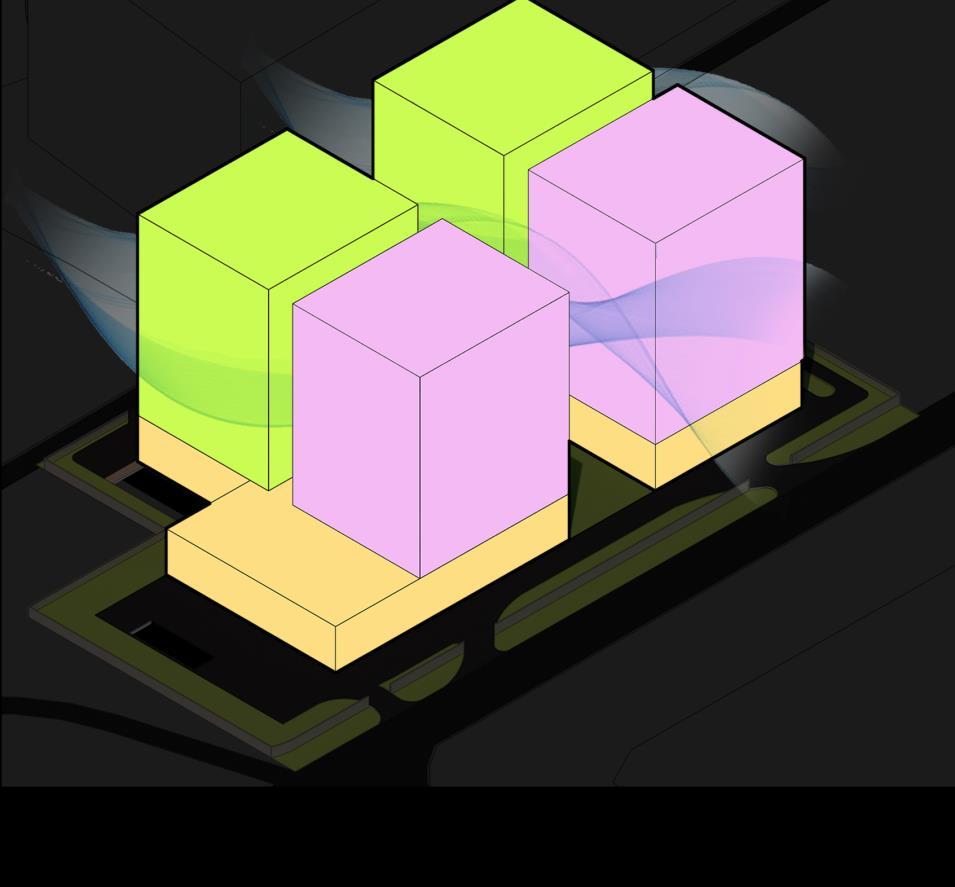
107 Project
1 – Thesis Synopsis
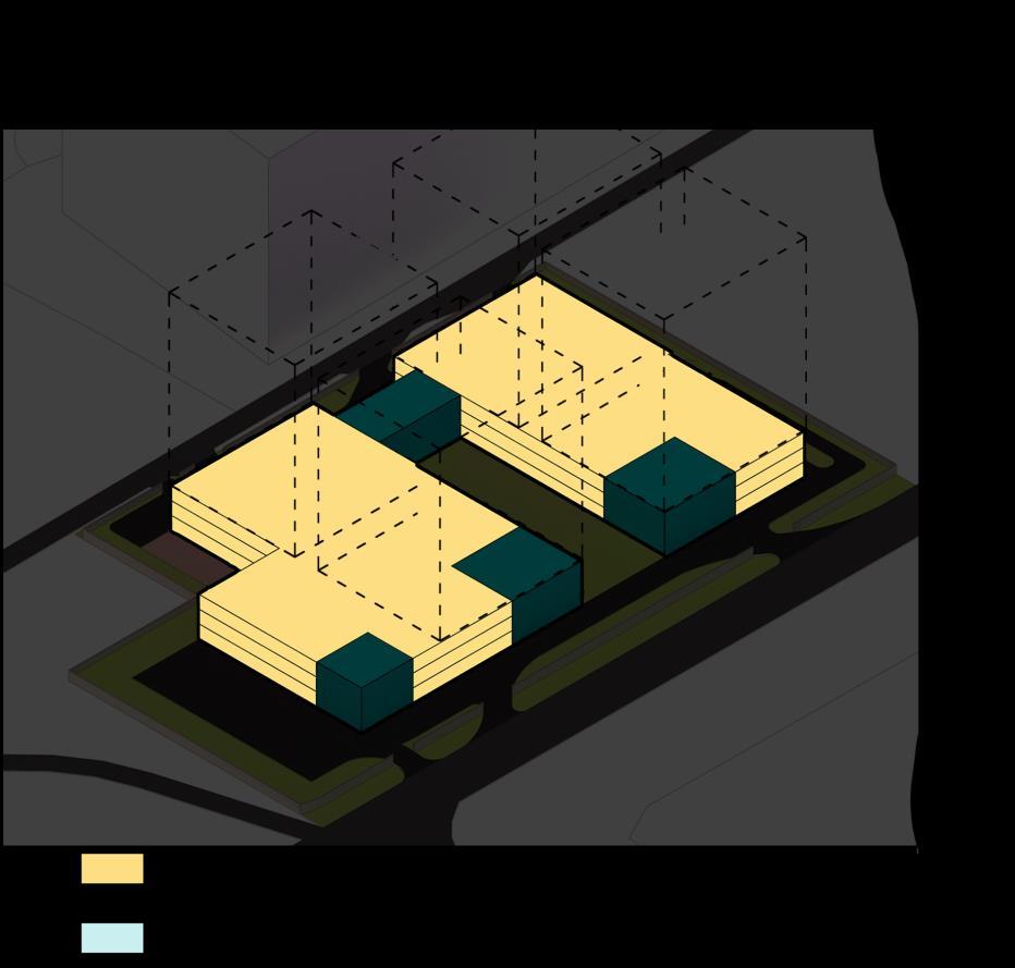
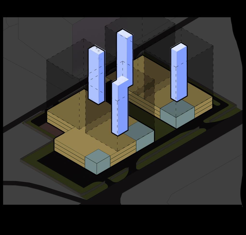
108 Project
–
1
Thesis Synopsis
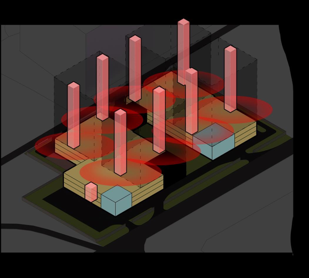
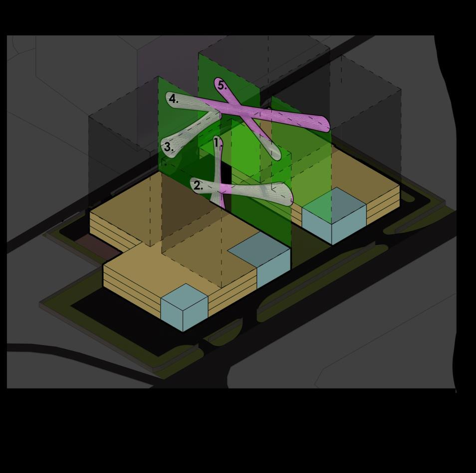
109 Project
–
1
Thesis Synopsis
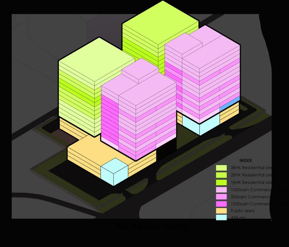
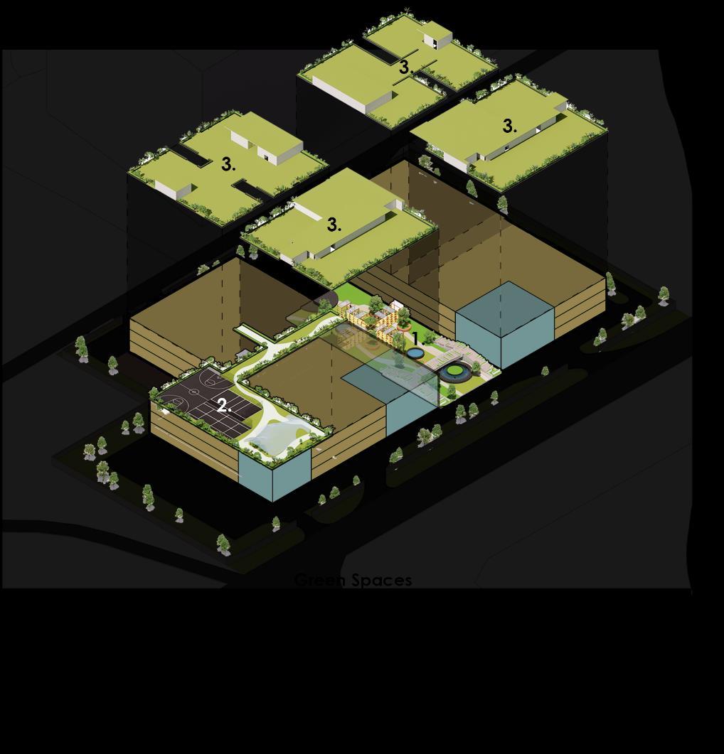
110 Project
–
1
Thesis Synopsis
Shading and Facade design
The Site is inclined at 30° to the east west axis. Thus the surafce will be exposed to the direct sun radiation. To reduce heat gain the shading devices like Cantiliver slabs and Green facade is used. The Industrial Perforated sheet with R value = and U value = is used.
Nature in the space
Visual Connection with Nature. Views of the sky gardens are accessible from nearly every Functional space; abundant indoor plantings and water features. Non Visual Connection with Nature. Odors from indoor plants; sounds of birds and insects attracted by native plants.
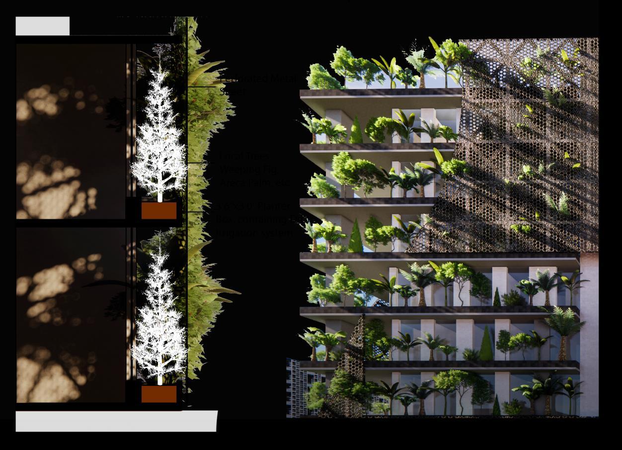
Non Rhythmic Sensory Stimuli. The wind rustling through trees on planted sky gardens; birdsongs.
Access to Thermal & Airflow Variability. Cool air flow from thewater features both inside and outside.
Presence of Water. Abundant water features incorporated into sky gardens,etc. Dynamic & Diffuse Light. Dappled light through the tree canopy & perforated sheet Connection with Natural Systems. Opportunities to observe interactions between birds, insects, and plants.
111 Project 1 – Thesis Synopsis
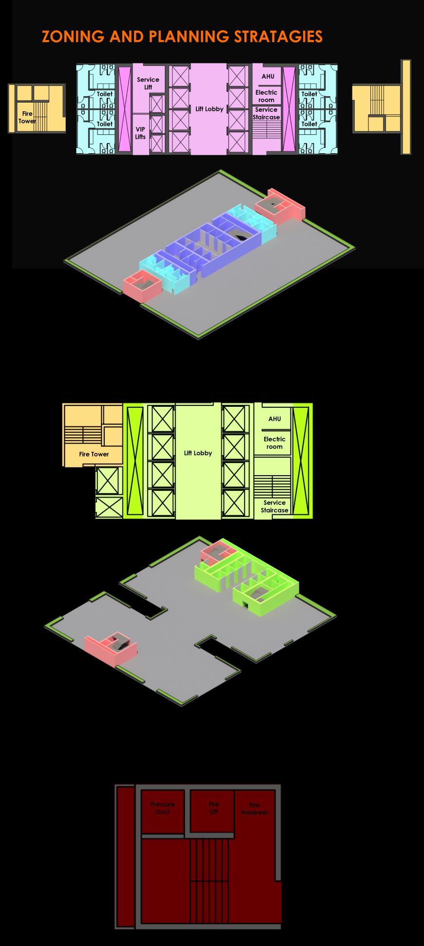
112 Project
1 – Thesis Synopsis
CHAPTER IV
THE DESIGN
113 Project 1 – Thesis Synopsis
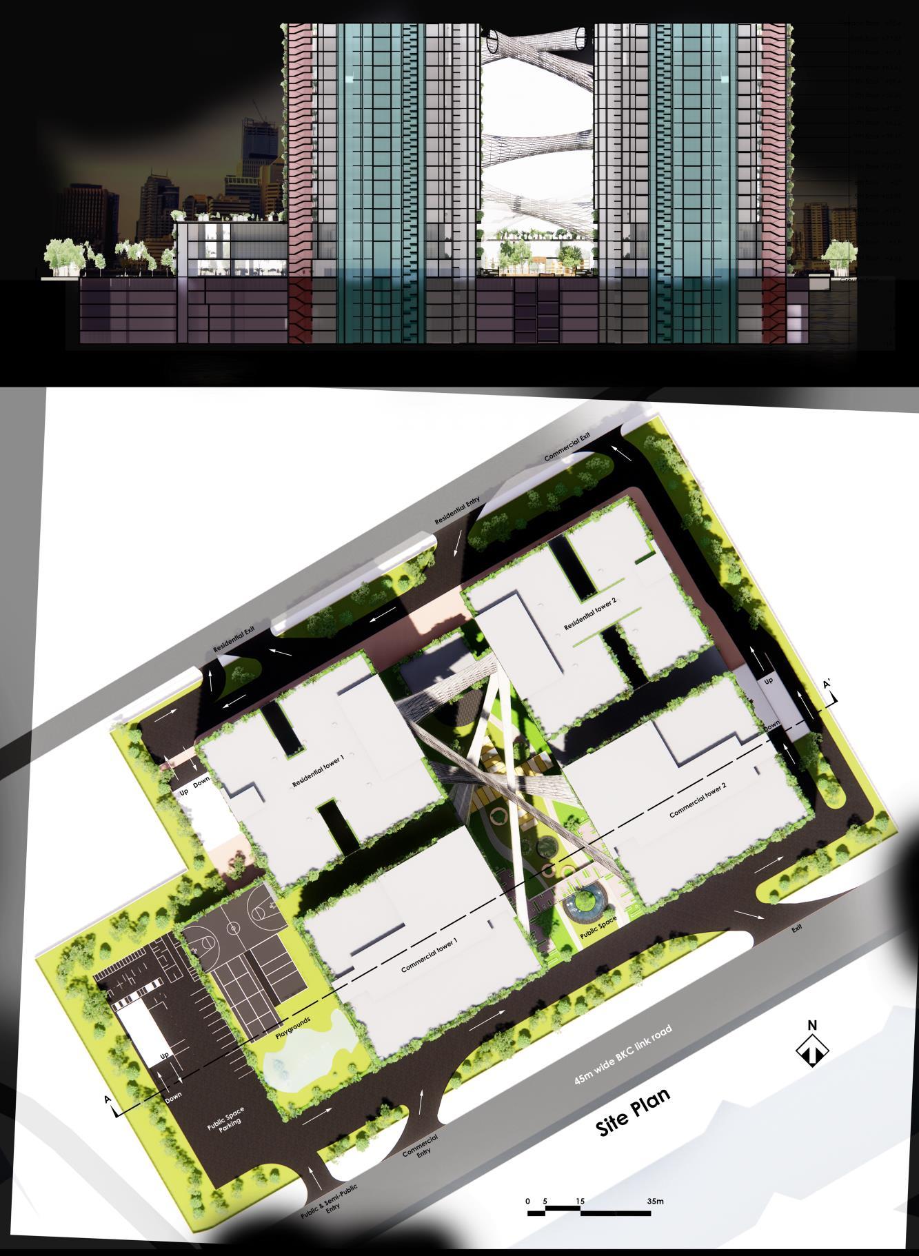
114 Project
1 – Thesis Synopsis
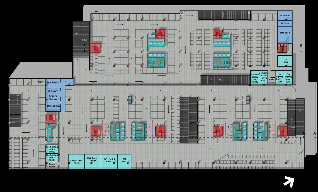
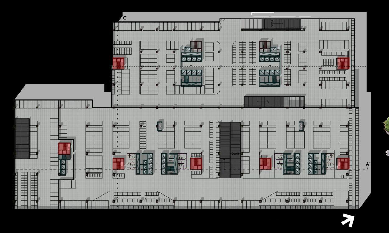
115 Project
–
1
Thesis Synopsis
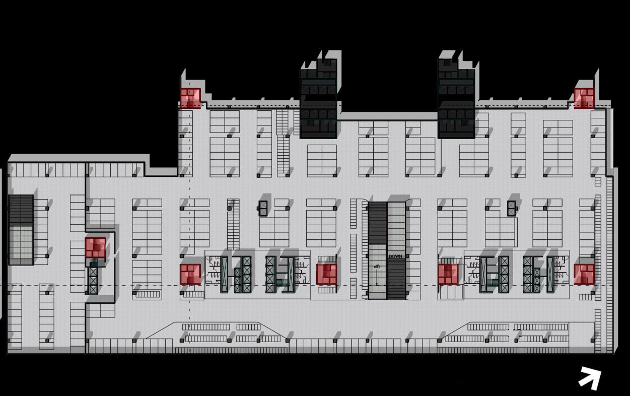
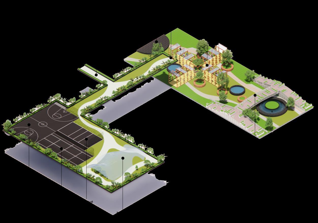
116 Project
–
1
Thesis Synopsis
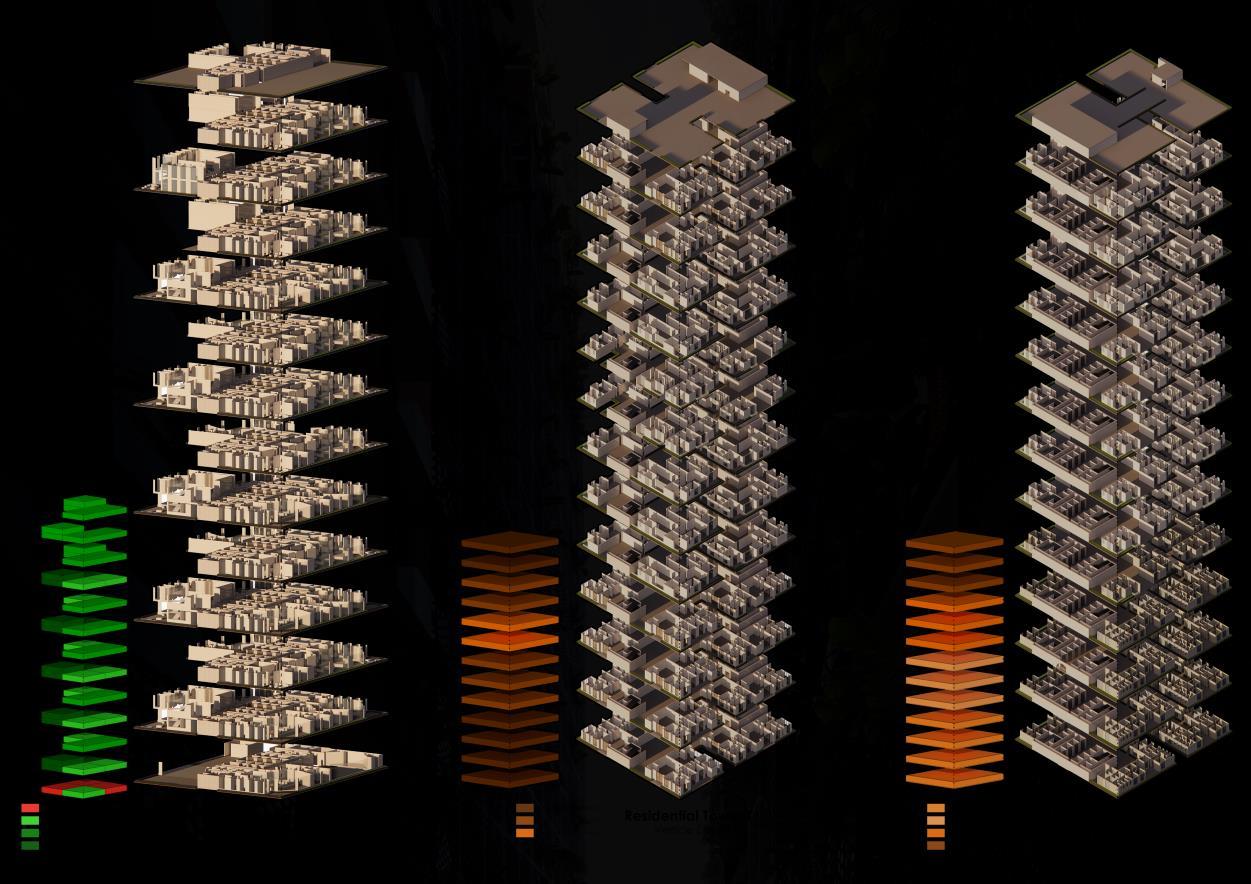

117 Project
1 – Thesis Synopsis
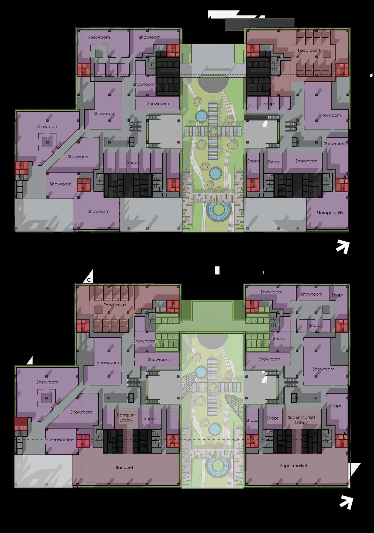
118 Project
1 – Thesis Synopsis
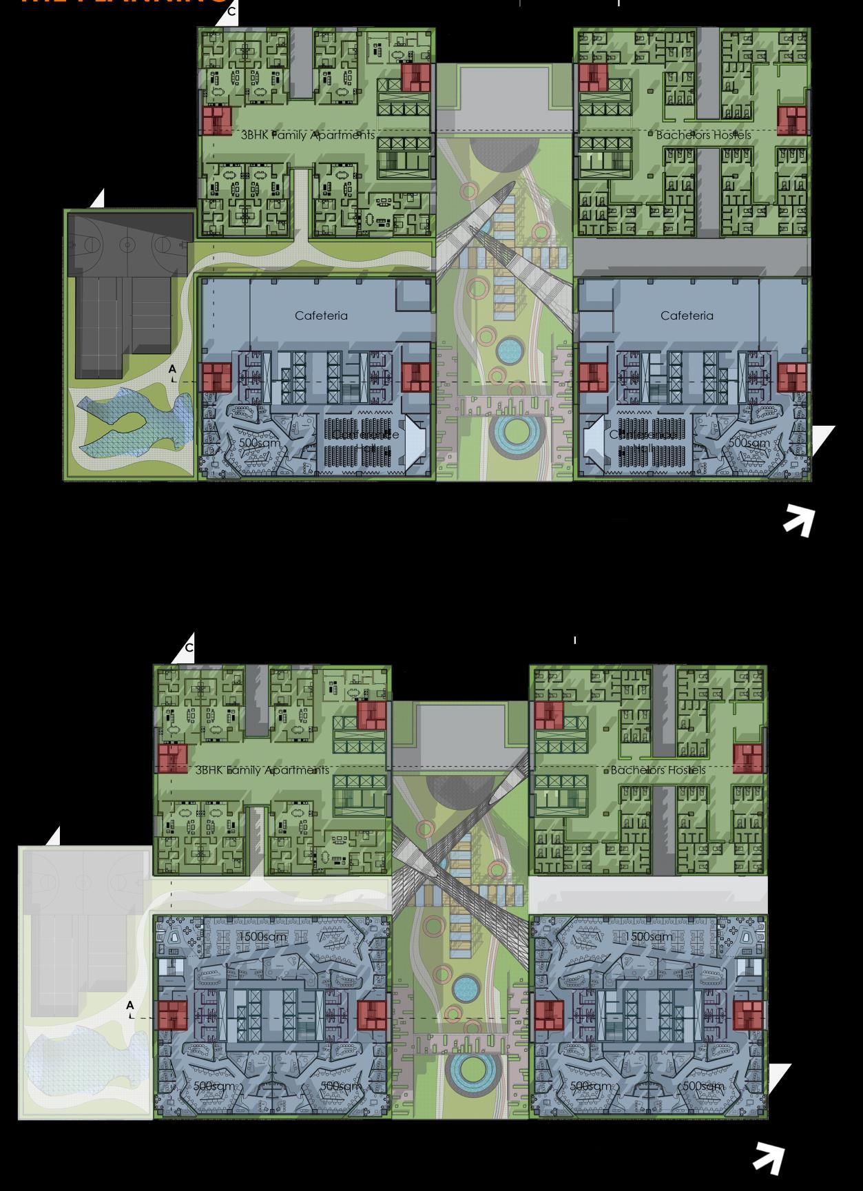
119 Project
1 – Thesis Synopsis
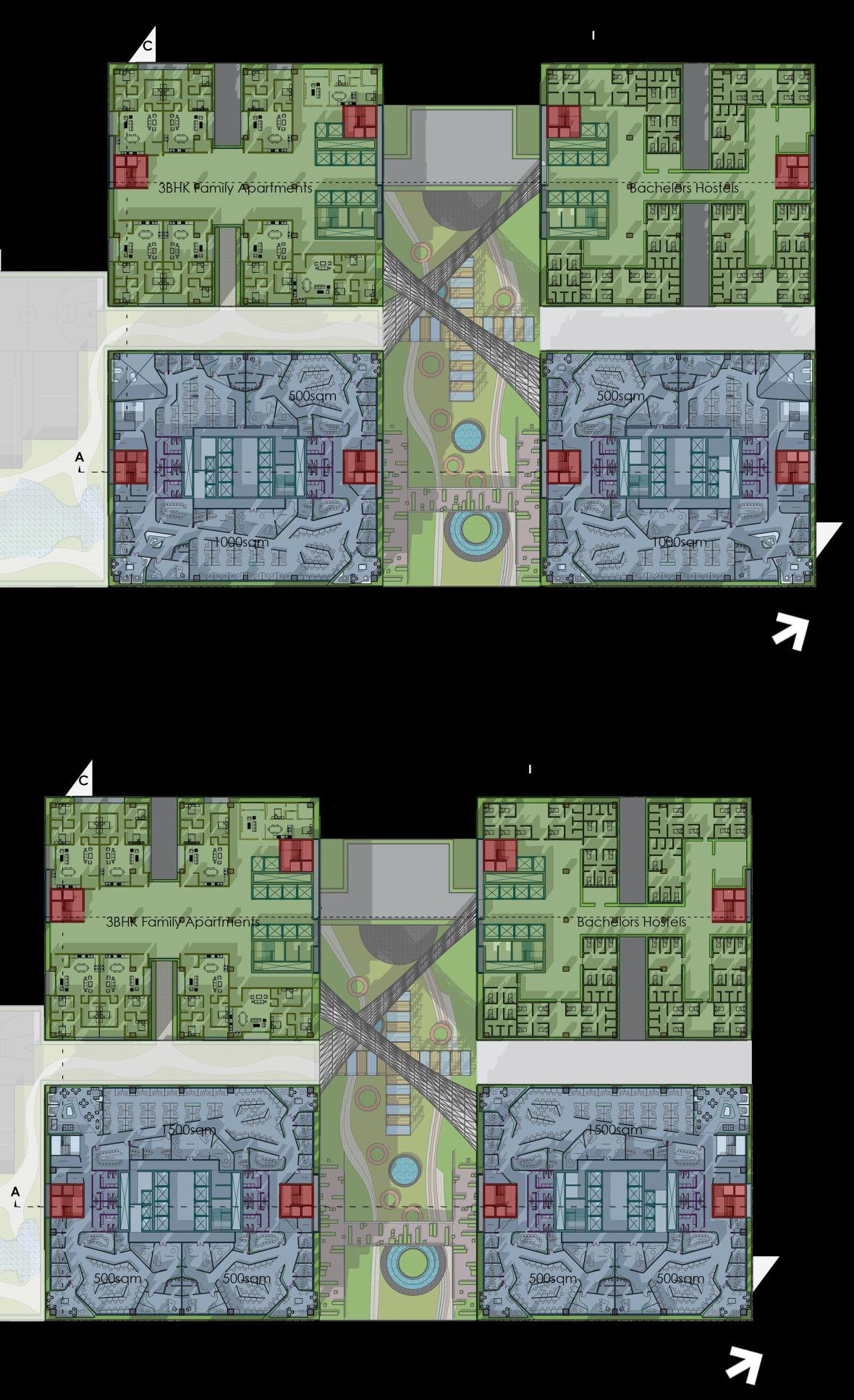
120 Project
1 – Thesis Synopsis

121
Project 1 – Thesis Synopsis
1 – Thesis Synopsis
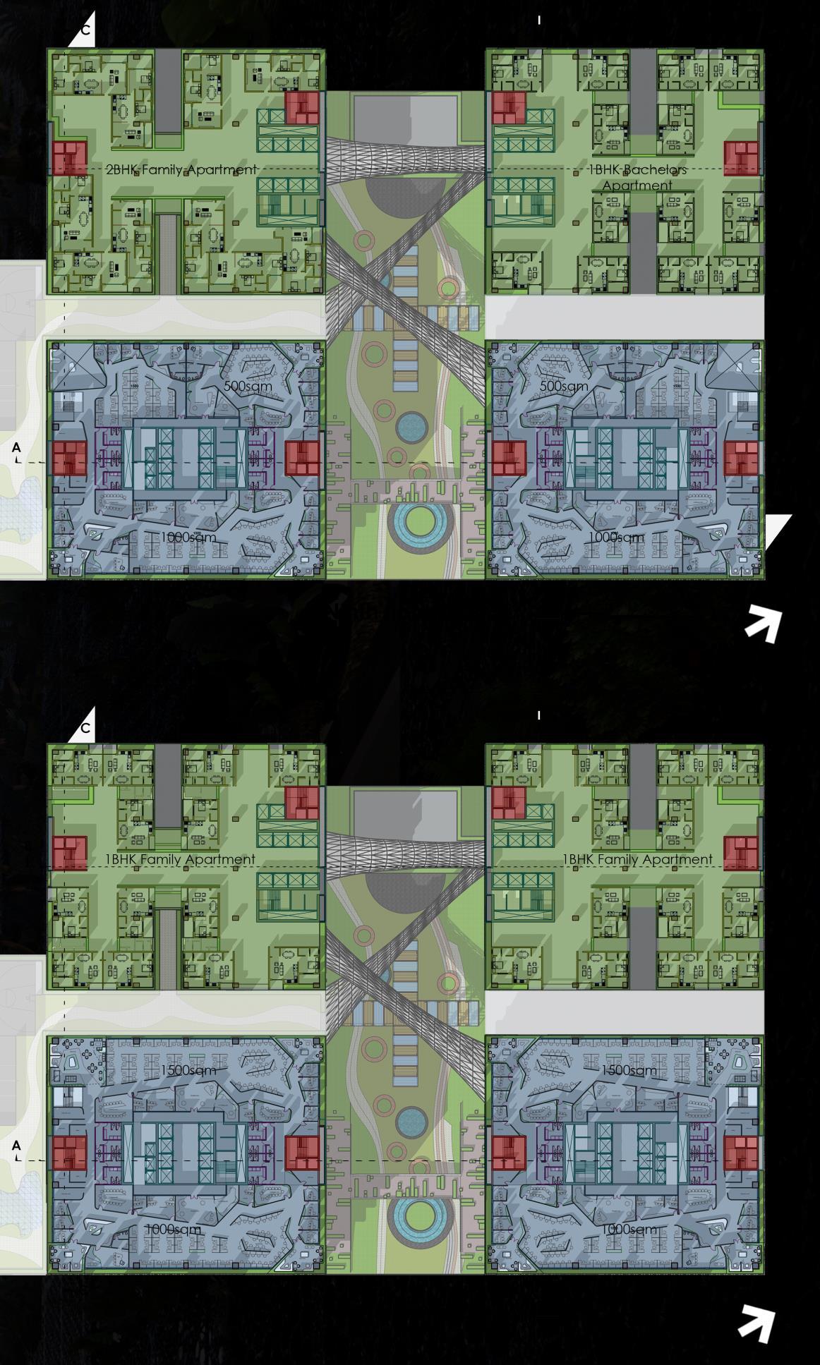
122
Project
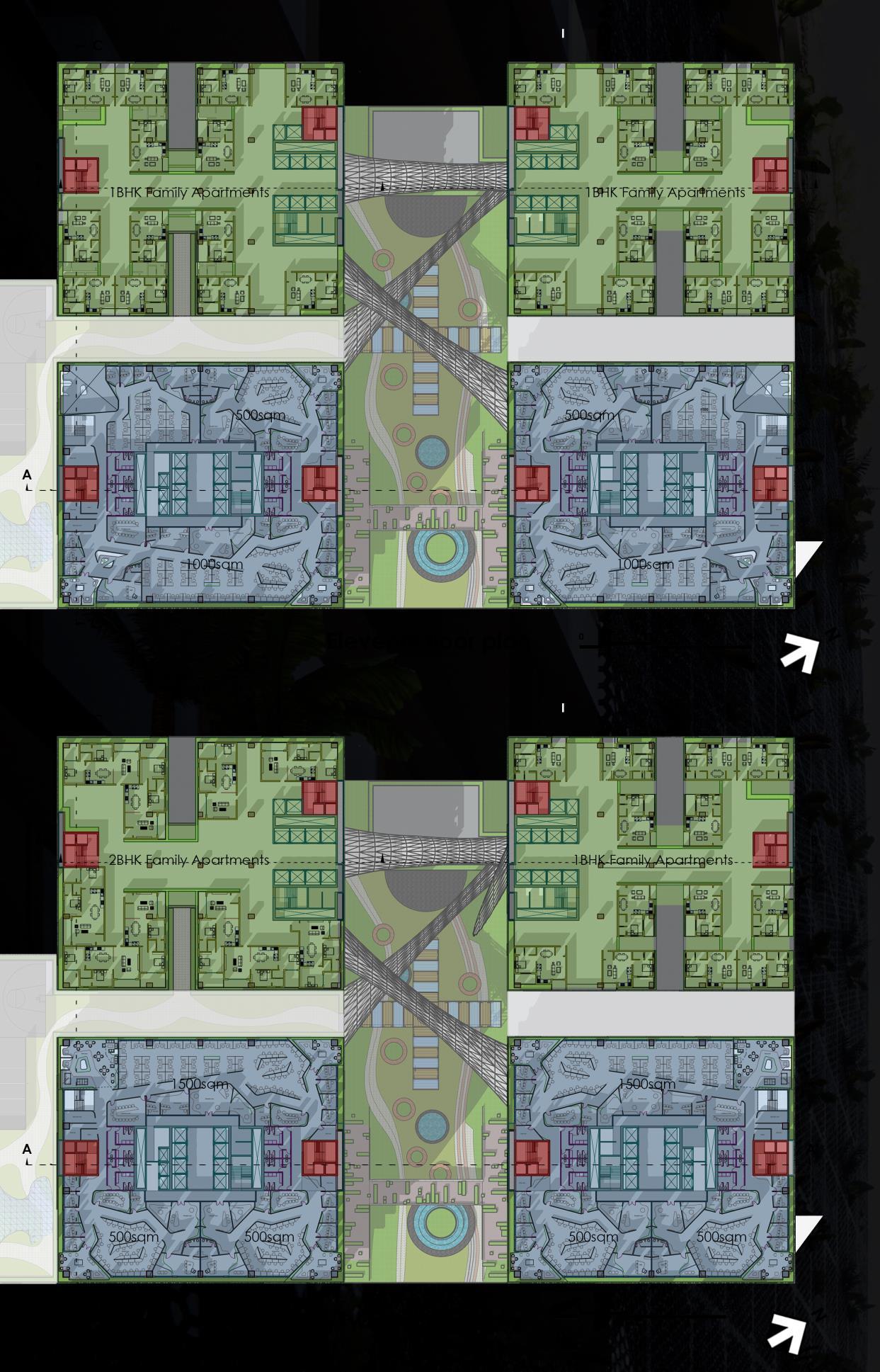
123
Project 1 – Thesis Synopsis
Synopsis
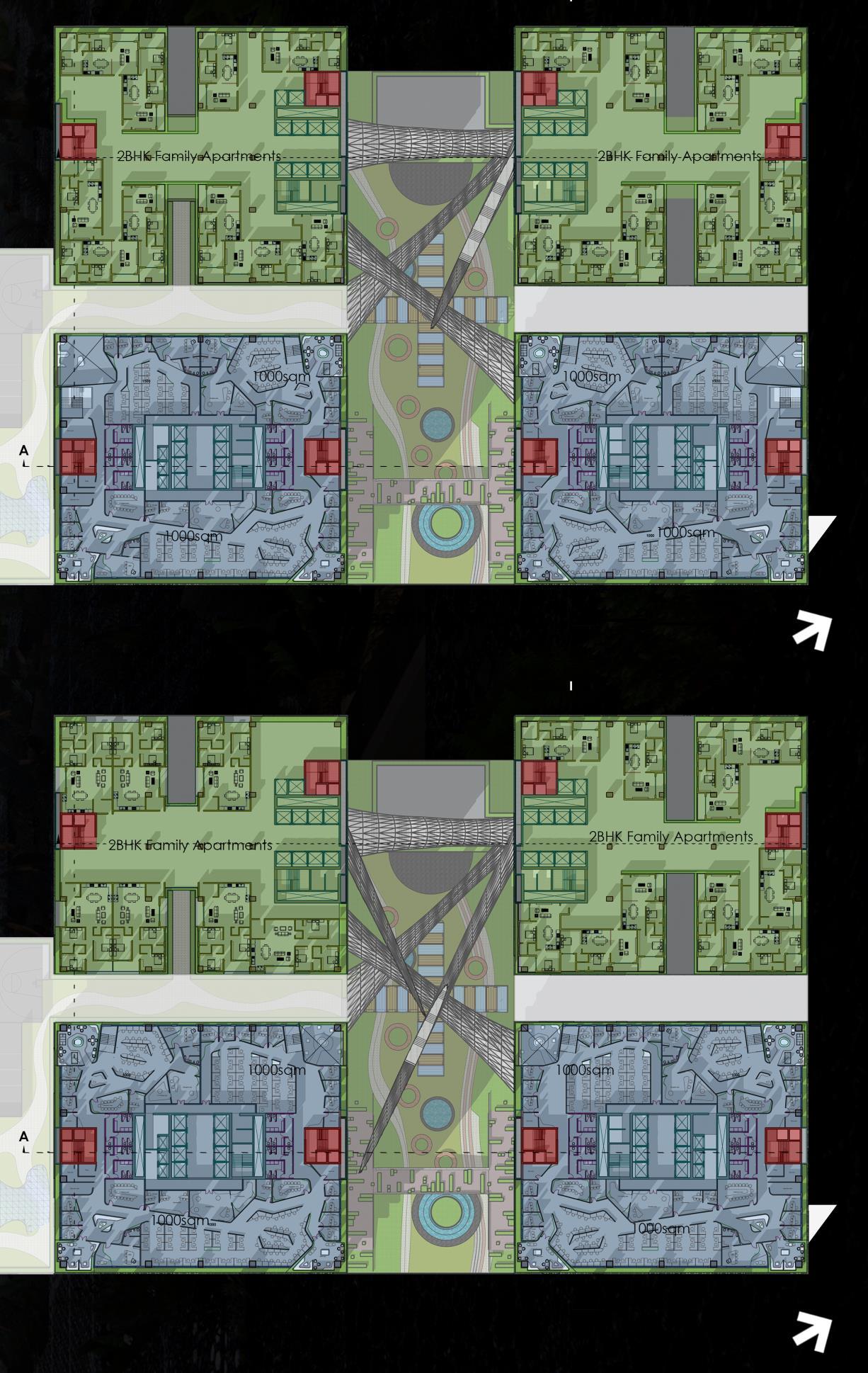
124
Project 1 – Thesis
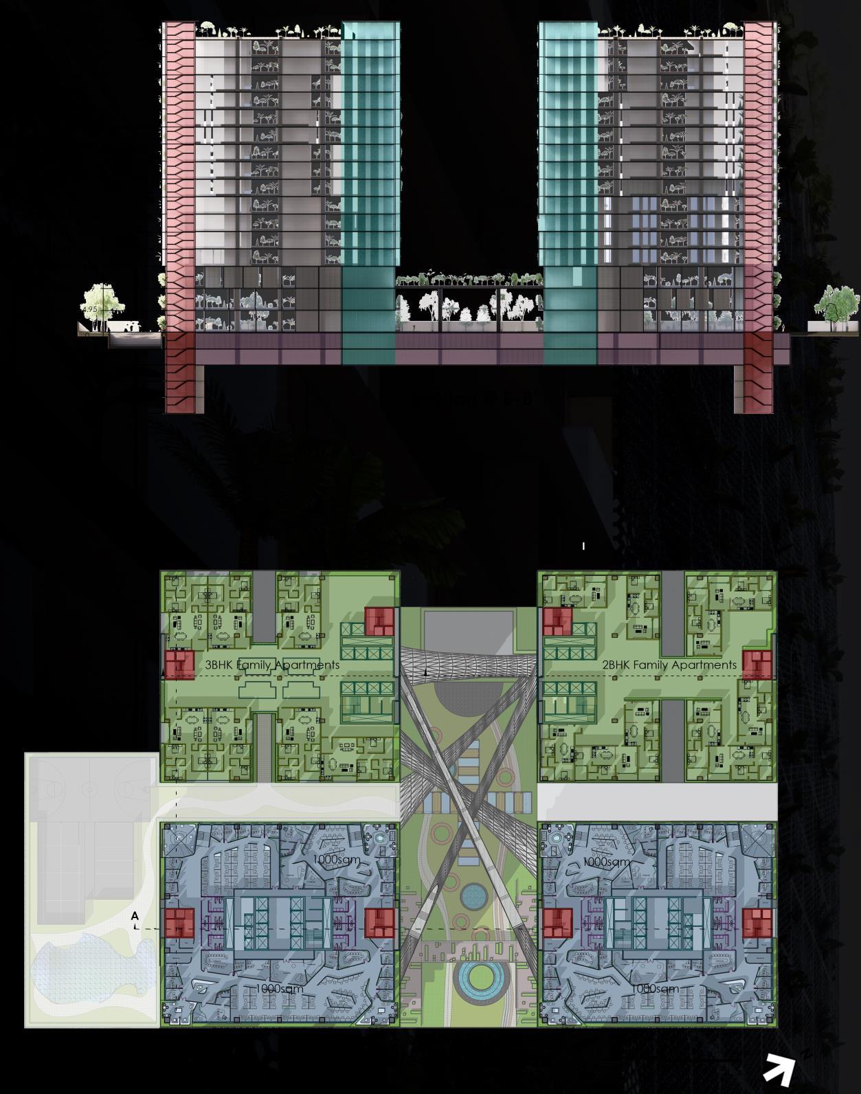
125 Project
–
1
Thesis Synopsis
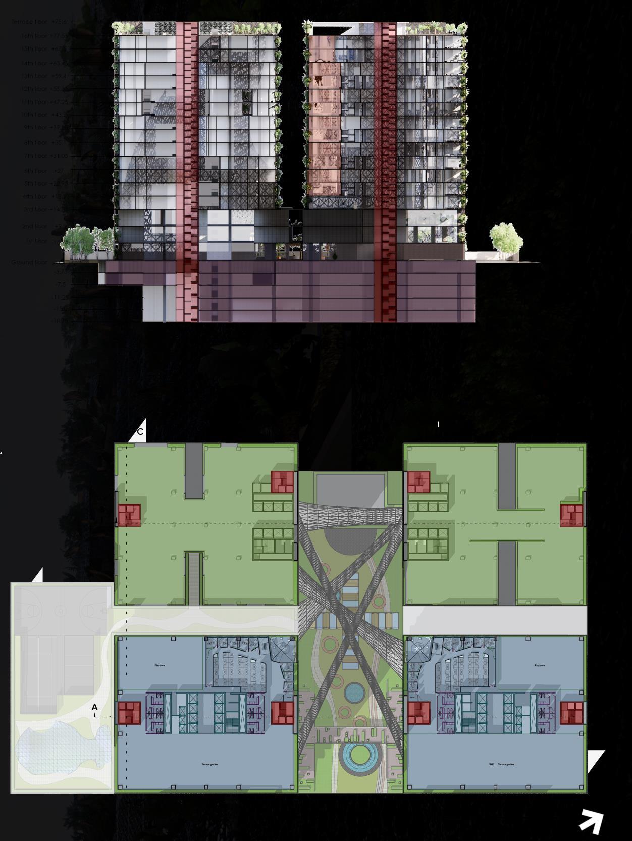
126 Project
–
1
Thesis Synopsis

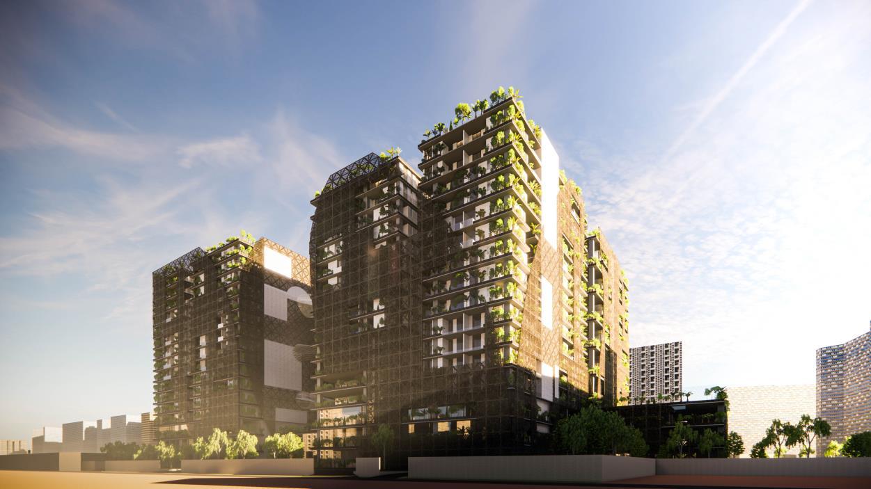
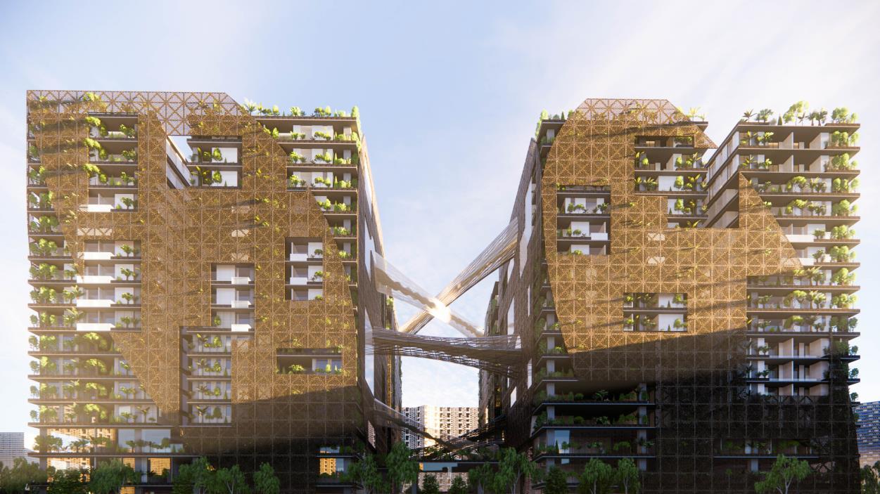
127 Project
1 – Thesis Synopsis
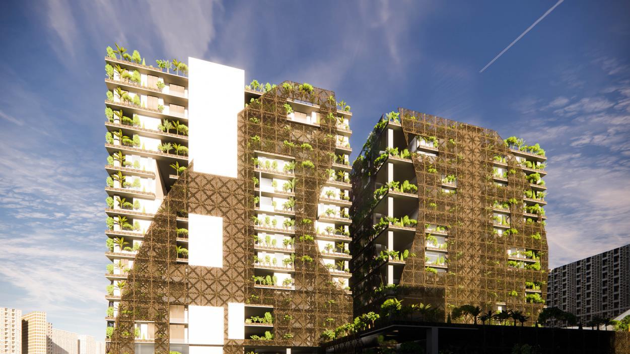
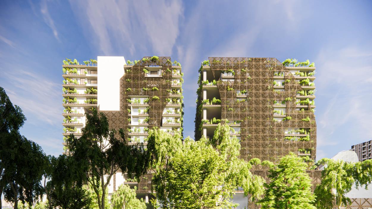
128 Project
1 – Thesis Synopsis
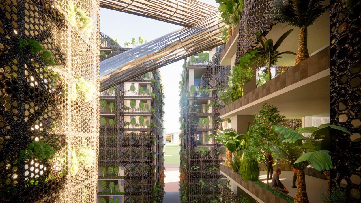
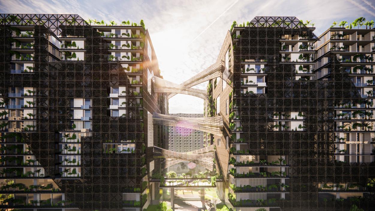
129
Project 1 – Thesis Synopsis
Synopsis

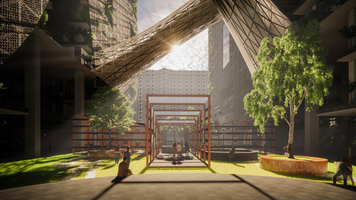
130
Project 1 – Thesis
Synopsis
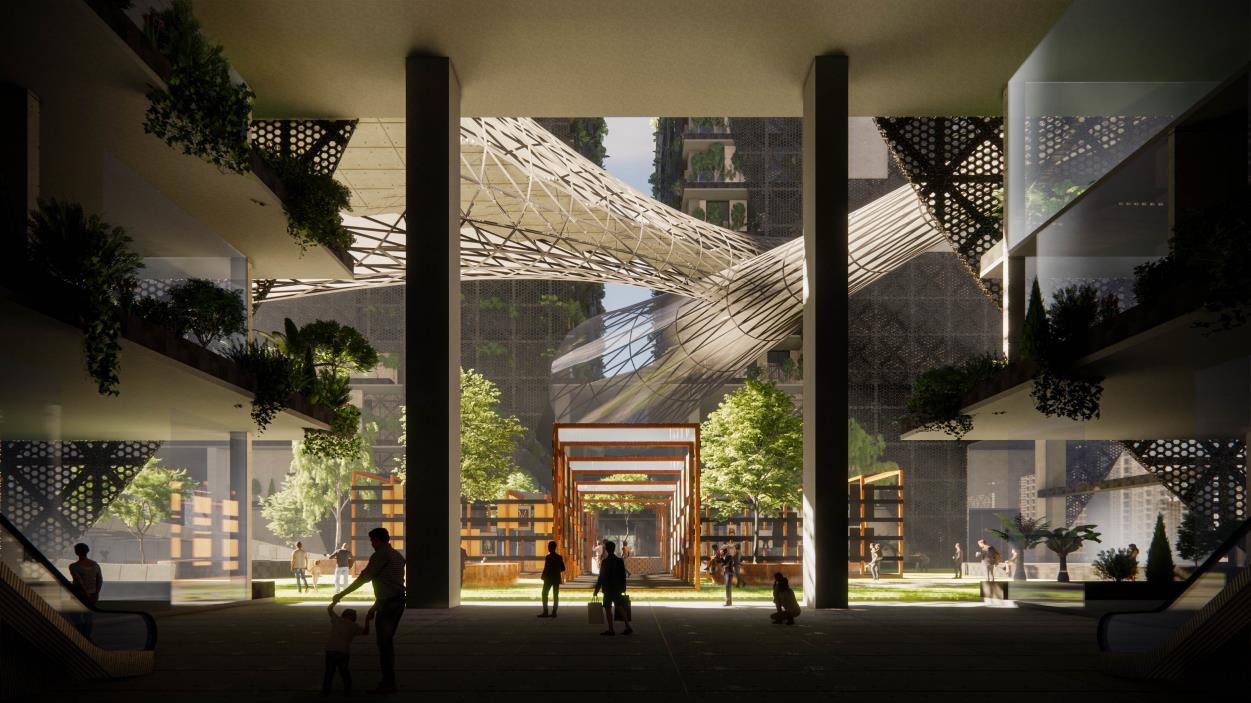
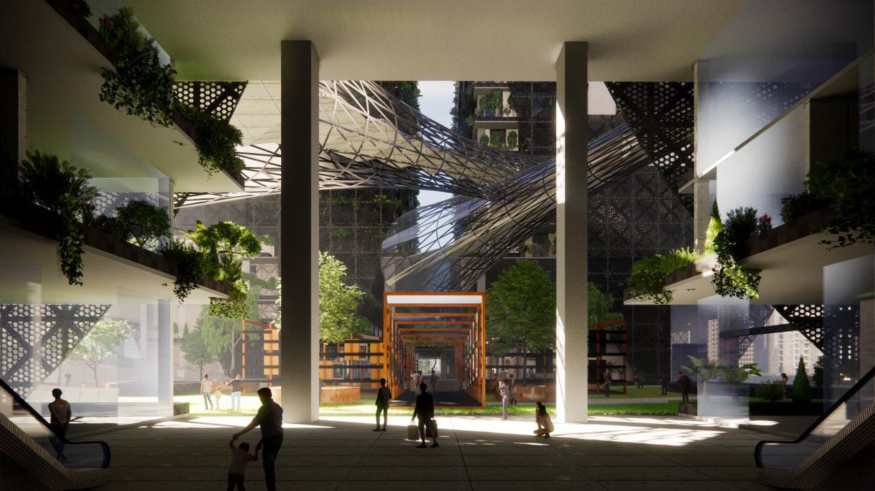
131
Project 1 – Thesis
Synopsis
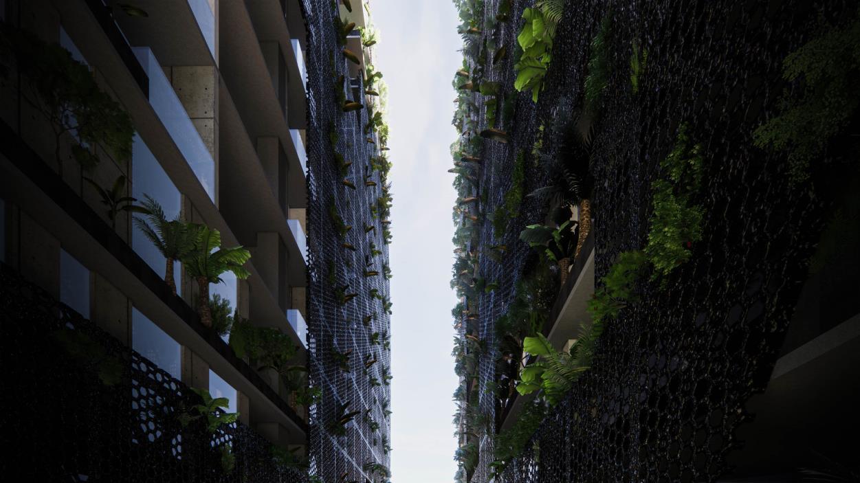
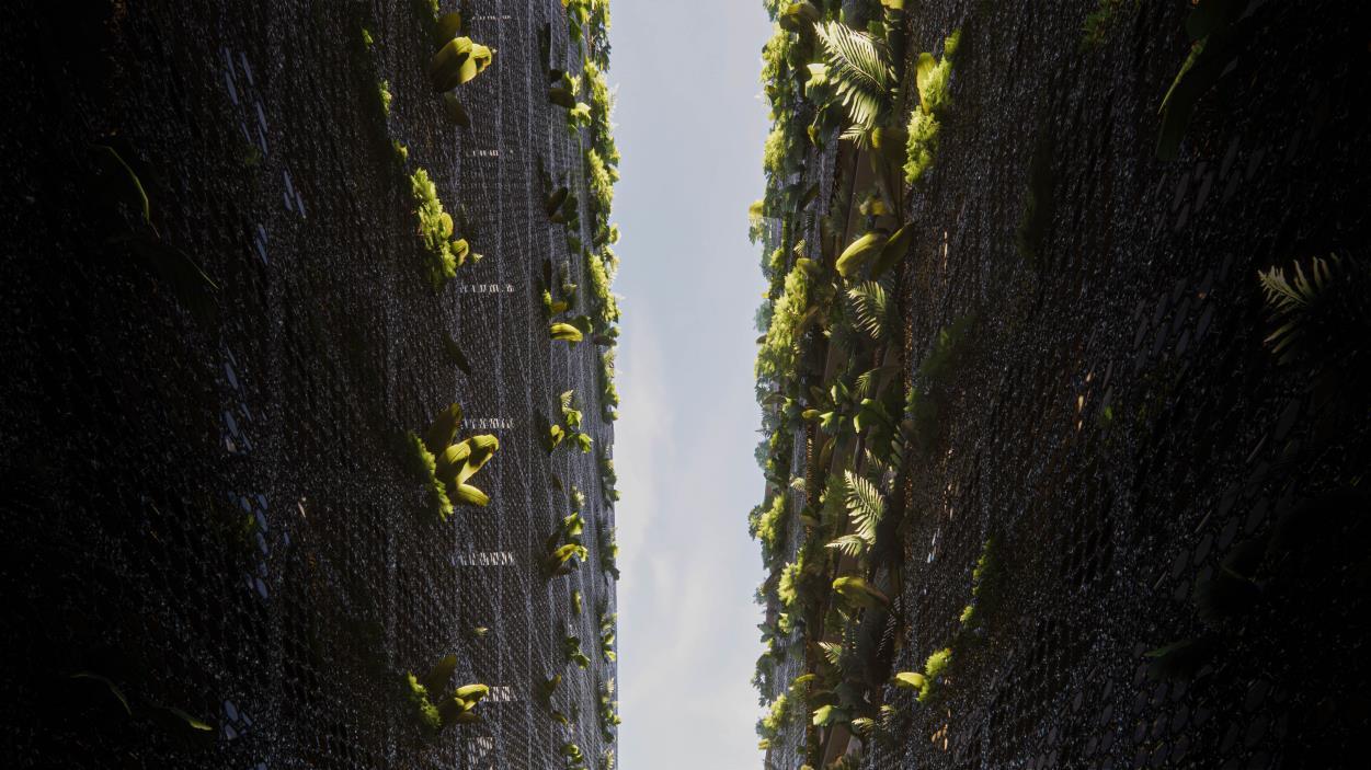
132
Project 1 – Thesis
Synopsis
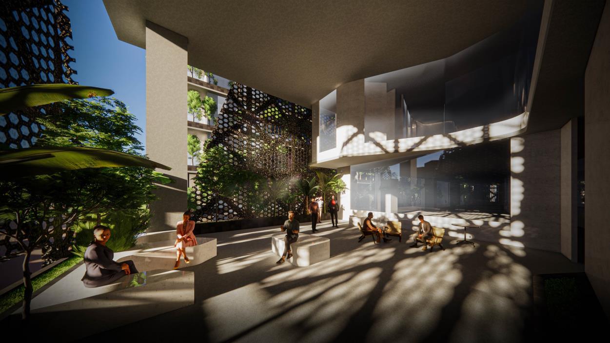
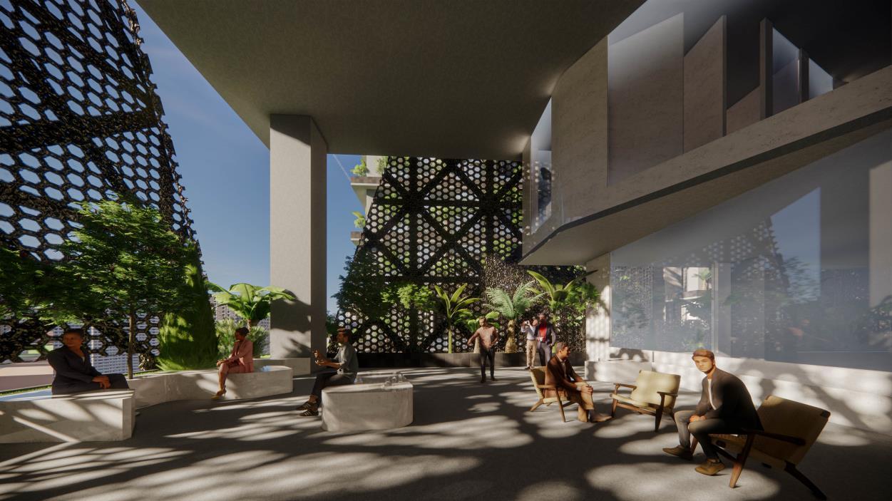
133
Project 1 – Thesis
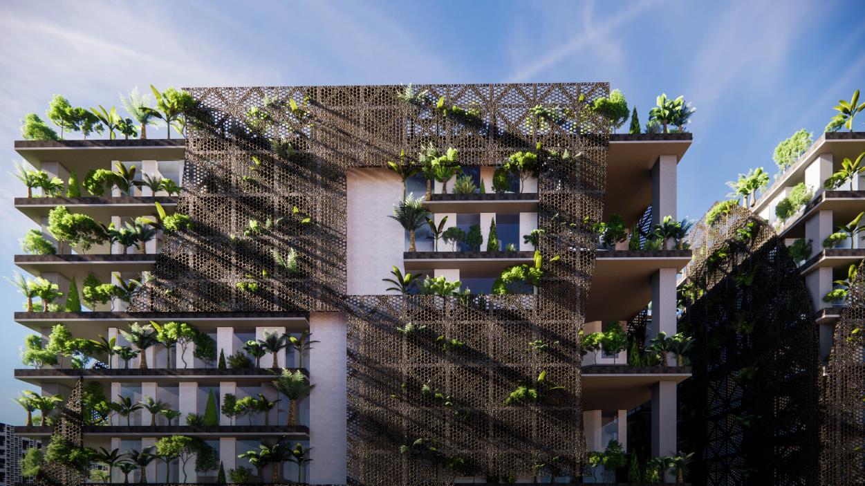
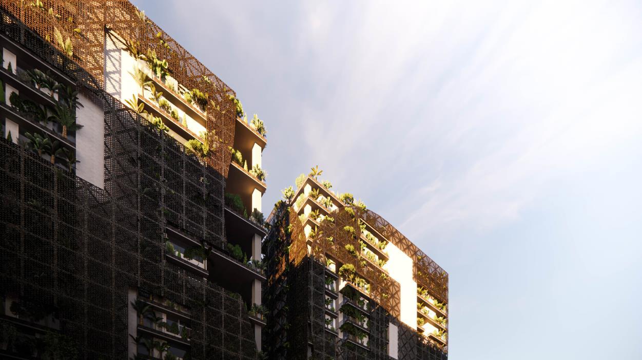
134 Project
–
1
Thesis Synopsis
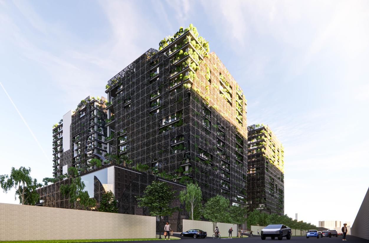
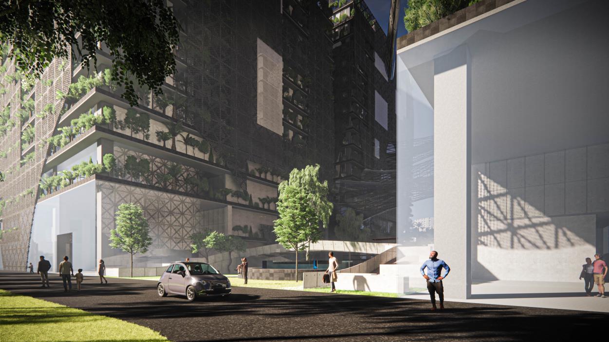
135 Project
–
1
Thesis Synopsis
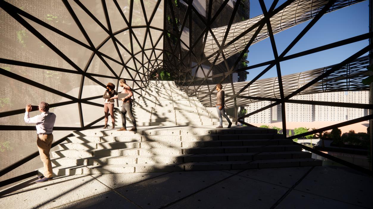
136 Project 1 – Thesis
Synopsis


 PETER SIMMONDS


