13 minute read
AIRAH News
COME TOGETHER
Can leading businesses and institutions across the HVAC&R spectrum join forces to create new climate and energy solutions? The Innovation Hub for Affordable Heating and Cooling is banking on it.
Advertisement
Air conditioning and refrigeration accounts for almost a quarter of all electricity generated in Australia. It is responsible for about 12 per cent of Australia’s CO2 emissions, and makes up about half of peak electricity demand across different parts of the electricity network. In view of this, the Innovation Hub for Affordable Heating and Cooling (i-Hub) was created to bring about a step change in our industry. The idea is to create a common platform on which leading businesses and institutions can discuss and adopt an integrated approach to developing more affordable heating and cooling solutions.
GETTING CONNECTED
The initiative is led by AIRAH in conjunction with the CSIRO, Queensland University of Technology, the University of Melbourne and the University of Wollongong and supported by the Australian Renewable Energy Agency (ARENA).
The i-Hub brings together leading universities, researchers, consultants, building owners and equipment manufacturers to create a connected R&D community in Australia. The aim is to support the HVAC&R industry with knowledge dissemination, skills-development and capacity-building. HVAC&R industry’s transition to a low-emissions future, stimulating jobs growth, and showcasing HVAC&R innovation in buildings.
“The i-Hub project brings a uniquely concerted effort from the HVAC&R and property industries to use the design and operation of air conditioning services as a tool for supporting onsite and local grid renewables,” says AIRAH CEO Tony Gleeson, M.AIRAH.
“Through the deferral of HVAC&R loads – during renewable energy supply shortages – and the use of HVAC&R loads as a ‘productive source of demand’ during periods of excess supply, this project will increase the value of onsite renewable energy production and increase the fraction of building energy that can be economically provided by onsite renewable energy.”
INNOVATION PLATFORMS
The i-Hub project is made up of three interlinked initiatives. They are the Smart Building Data Clearing House, Living laboratories – Green Proving Grounds, and Integrated Design Studios. Their role is to support the HVAC&R industry with knowledge dissemination, skills-development and capacity-building. Each of the initiatives has a clearly defined scope and agenda.
The i-Hub Data Clearing House was developed to support Australian innovation in the area of smart controls and the digitalisation of buildings.
The Living Laboratories aim to provide real-world validation of technologies that integrate onsite renewable energy and HVAC loads to improve the value of renewable energy in front of major building portfolio owners.
With a view to facilitate integrated design in the industry, the i-Hub Integrated Design Studio aims to explore its development between architects, engineers, and clients in a project environment.
TECHNOLOGICAL BET
At a time when rising electricity costs are putting enormous pressure on Australian consumers and businesses – a problem made worse by COVID-19 – initiatives like the i-Hub are betting on technology to reverse the trend.
The i-Hub reflects the strong desire to support Australian innovation in delivering better energy efficiency and minimising peak demand. The project also aims to deliver innovative solutions that have renewable energy and building efficiency at their core.
Stark as the current energy and climate challenges are, new market opportunities abound for smart energy and energy-efficient products and services.
The i-Hub is working to assist the HVAC&R industry’s transition towards a low-emissions future. In so doing, it is strengthening Australia’s position to lead the global market for smart and zero-energy buildings. ■
IT’S A BLAST
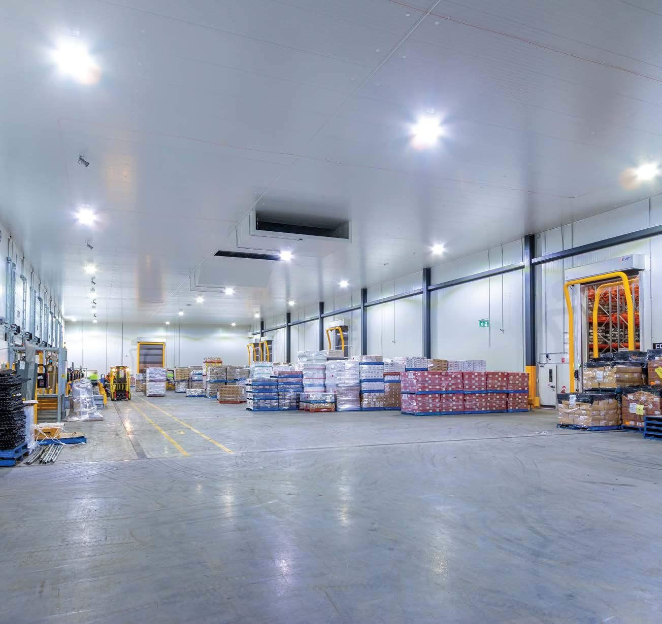
Through the adoption of an innovative, centralised low-charge NH3 solution, significant energy savings are being realised by a major Victorian logistics operator at its new cold store facility in Melbourne’s west.
Located in Truganina in Melbourne’s outer west, this new refrigerated warehouse facility is the result of a decision by the operator to consolidate three existing facilities into one.
It presented an opportunity for the third-party logistics (3PL) operator to move away from traditional air-cooled HFC and CFC systems, and consider a future-proof, energy-efficient alternative for its new facility.
Having not operated a facility refrigerated by ammonia, the operator was introduced to the concept of a centralised low-charge NH3 (ammonia) refrigeration system by Scantec Refrigeration Technologies. featuring blast freezers served by the same type of refrigeration plant.
After this inspection, and considering the estimated energy cost savings of about $40,000 per month, reductions in maintenance costs and a five-year payback period, a decision to proceed was made in mid-2019.
The new Truganina refrigerated warehouse facility has been designed to incorporate a blast freezing facility within the refrigerated storage space. It includes rack blast freezing for carton-packaged meat. When not in use, the rack can be used for pallet storage also. incorporates “cold lake” air distribution and automatic ambient air defrost.
The system services a freezer store, a dual-duty chiller/freezer and an ante room. The latter serves as a space that minimises infiltration into the freezer room(s) and enables marshalling of products during receipt and despatch.
The refrigeration plant employs insulated coolers where the coils and fans are contained within insulated air handling units (AHUs).
These insulated coolers are mounted in the ceiling space above the ante room, with access for all maintenance and repairs to the air coolers (evaporators) taking place outside the refrigerated spaces.
LESSONS FROM THE REFRIGERATION DESIGN ENGINEER
According to Scantec Refrigeration Technologies managing director Stefan Jensen, F.AIRAH, there are many challenges associated with the selection of refrigeration systems in the refrigerated warehouse sector.
He offers a few lessons that can be learned from the Truganina project.
BEST PRACTICE
“There is a total lack of best-practice energy performance benchmarking for refrigerated warehouses in Australia,” he says.
“Building occupants, contractors, developers, landlords, consultants, and construction companies therefore have no tool(s) and/or standards with which a qualitative assessment of refrigeration systems can be performed prior to installation. This usually leads to the lowest capital cost option(s) being accepted. This was prevented in this case.”
ENERGY EFFICIENCY VITAL
“It is in the commercial interest of the facility owner/ landlord to ensure that a refrigeration plant with the highest level of energy efficiency is installed even though that entity may not be responsible for energy consumption costs,” says Jensen. “This is the case because an energy-efficient refrigeration plant adds value and assists in tenant retention.”
SUMS STACK UP
“Based on the recorded energy performance of this new facility, there is evidence emerging that the difference in energy costs between this and a typical low-efficiency neighbouring facility will pay for a complete replacement plant every four to five years,” says Jensen. “What this means is that for building occupants who lack capital, but have a past track record of being able to fund excessive energy costs, a finance option for an energy-efficient replacement plant concept that has a track record may be within reach.”
COLD LAKE
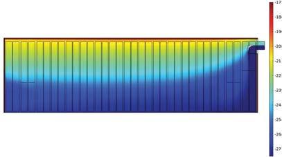
The “cold lake” air-distribution concept employed by Scantec Refrigeration Technologies at Truganina relies on the differences in density between relatively cool and relatively warmer air. “In any refrigerated warehouse, it is the circulating airstream that cools the space,” says Jensen. “The airstream does this by warming up slightly as it circulates throughout the facility. As the air warms, the density reduces, and the air seeks to rise towards the ceiling of the facility without requiring any mechanical assistance to do so.”
From there, the air returns to the evaporator (air cooler) return, is refrigerated again and returned to the room.
This is in contrast to the conventional air-distribution method, which injects relatively cold air at high level into the refrigerated space, forcing the airstream to more or less do the opposite of what it naturally seeks to do when used as the cooling agent cooling the warehouse.
The above visualisation depicts typical temperature distribution for the freezer store inside elevation.
“There are certain dimensional criteria that the warehouse needs to satisfy to achieve the most optimal outcome,” says Jensen.
Firstly, a certain length-over-height ratio range needs to be satisfied to avoid the use of auxiliary fans. Secondly, there needs to be space below the racking for the refrigerated air to distribute evenly throughout the facility.
“Because air distribution relies more on air density differences as opposed to mechanical work,” Jensen says, “fan power is reduced and ducting within the refrigerated facility is eliminated.”
In addition, structural loads are positioned close to walls, and refrigerant pipelines in the ceiling cavity above the freezer(s) are eliminated, as are all condensation risks.
AMBIENT AIR DEFROST
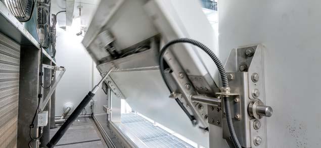
Defrost is carried out by means of automatic motorised shutters. During defrost the cooling coil is isolated from the refrigerated warehouse on the air side, while ambient air is circulated through the cooling coil, causing it to defrost. This minimises heat ingress into the freezer during defrost.
The use of dry expansion refrigerant feed and the employment of evaporator materials with high thermal conductivities create a faster defrost cycle. The reason for this? Air coolers contain significantly less refrigerant at the commencement of the defrost, and warm up faster.
In the event of a refrigerant leak, the air cooler is forced into defrost mode. This prevents leaked refrigerant from entering the refrigerated space.
Any ammonia exposure risk in the freezer(s) is further mitigated by the inherently lower operating refrigerant inventory in the air coolers of low-charge NH3 refrigerated systems. The operating evaporator refrigerant inventory is typically 30–50 times lower than conventional liquid overfeed ammonia plant. The overall plant inventory is typically four to five times lower.
At Truganina, the total refrigerant inventory is about 475kg. This is below the threshold that classifies the site as a Dangerous Goods Storage facility. “If the facility has been serviced by a conventional liquid overfeed refrigeration plant, the ammonia inventory would have been 2,000 to 2,500kg,” Jensen says. The operating refrigerant inventory in all air coolers combined is about 25kg – up to 40 times lower than conventional liquid-overfeed systems. “The significantly lower refrigerant inventories in the air coolers and in the plant as a whole, contribute to an installation that is safer than conventional plant with liquid overfeed,” Jensen says.
ENERGY SAVINGS
Well known for its work in the design of NH3 refrigeration systems across a variety of sectors from Far North Queensland to Western Australia, Scantec Refrigeration Technologies has collected sufficient data to accurately compare the energy efficiency that this type of plant offers against other plant concepts. “The superior energy efficiency is the key feature that delivers above-average returns on investment,” Jensen says.
This is evidenced by the green dots in the graph below, that represent a number of centralised low-charge NH3 plants. In some cases, energy
Energy use [kWh/m3 -yr]
120
100
Lismore (DX Ammonia with(DX Ammonia with screw compressors) screw compressors)
5 5 ASHREA Guide for Sustainable Refrigerated FacilitiesASHREA Guide for Sustainable Refrigerated Facilities
Scantec Refrigeration Technologies – Scantec Refrigeration Technologies – DX AmmoniaDX Ammonia
Scantec Refrigeration Technologies – Two Stage Liquid RecirculateScantec Refrigeration Technologies – Two Stage Liquid Recirculated d
Power (Scantec Refrigeration Technologies – Power (Scantec Refrigeration Technologies – DX Ammonia)DX Ammonia)
60 Melbourne Melbourne (Transcritical (Transcritical CO2)CO2)
4 4
1 1
40 T TamworTamworth th 8 8
10 10
3 3
PerthPerth Banks meadowBanks meadow w M Melbourn Melbourne e 20 Townsville Gillman Townsville Gillman e man n (DX Ammonia) Yatala (DX Ammonia) YatalaY SRT SRT 9 9 9 2 2
6 6
SRT SRT 7 7
9 9 S SRT SRT 6 6
S SRT SRT 3 3 S SRT SRT 4 4
T Trade StreetTrade Street ICCL Malaysia (estimated)ICCL Malaysia (estimated) S SRT SRT 8 8
S SRT SRT 5 5
7 7
SRT SRT 2 2 S SRT SRT 1 1
consumption levels are several times lower than the conventional systems also featured in the graph.
According to Jensen, it is also evident that there is a greater level of predictability associated with the specific energy consumption (SEC) of centralised low-charge NH3 plant.
“The SEC values on the vertical axis are recorded in kWh/m3/year,” Jensen says, “where the volume in m3 refers to refrigerated volume.”
Other benefits of this installation type include the use of all stainless steel pipelines and stainless steel condenser, the elimination of ammonia pumps, and avoiding most of the liquefied refrigerant management problems associated with extensive periods of low loads and/or automatic re-start after power failures.
WINDOW OF OPPORTUNITY
One of the major challenges associated with the Truganina installation was the relatively narrow window of opportunity for insulated cooler installation. This relied on accurate installation programming to eliminate any installation delays. Additionally, the interface between the insulated cooler discharge and the freezer wall required acute attention to detail, both in design and installation. This helped avoid condensation issues, air leaks and expansion/ contraction damage.
Fortunately, with the bulk of the refrigeration work at Truganina already completed prior to the COVID-19 pandemic, the impact of Melbourne’s city-wide lockdown on the project was moderate.
COMMISSIONED AND OPERATING
Commissioning of the centralised low-charge NH3 refrigeration system commenced in late September 2020.
Despite some minor issues in association with the commissioning of the control of the automatic defrost flaps on the insulated coolers, the end-user was able to move their first pallets into the new facility in late November 2020.
To date, the system’s energy consumption is in line with expectations. ■
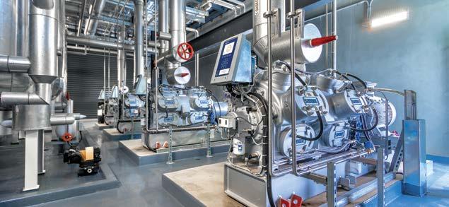
Centralised low-charge NH3 engine room holding less than 500kg of ammonia.
LOCATION, LOCATION
In designing the centralised low-charge NH3 refrigeration system at Truganina, Scantec Refrigeration Technologies elected to locate all air coolers (evaporators) outside the refrigerated space.
As well as simplifying maintenance, this design is able to utilise the ceiling space often available above ante rooms, which have lower ceiling heights than freezer rooms.
The location of the air coolers outside the refrigerated space also reduces noise levels, improves operator safety, simplified the refrigerant pipework design and installation, eliminated any protrusions or obstructions within the refrigerated warehouse and improved refrigerant leak management.
Defrost and emergency ammonia venting are carried out by means of automatic motorised shutters.
COMPARING AMMONIA
The below chart provides a comparison between a typical centralised low-charge NH3 refrigeration plant and a range of other refrigeration plant concepts.
The small green star represents a Brisbane refrigerated storage facility serviced by a low-charge NH3 plant, commissioned in 2020. The remaining dots represent facilities owned and operated by one US-based entity specialising in refrigerated storage.
140
120
Two stage NH3
Two stage NH3 Two stage NH3
Two stage NH3
Plot area
80
60
40
20
0 Two stage NH3 Two stage NH3
Subcritical CO2/NH3
Two stage NH3 Two stage NH3
Single stage NH3 Single stage NH3
Two stage NH3 Two stage NH3 Subcritical CO2/NH3 Subcritical CO2/NH3
Subcritical CO2/NH3 Two stage NH3 Two stage NH3 Two stage NH3 Subcritical CO2/NH3
Two stage NH3 NH3 DX
NH3 DX Two stage NH3 Two stage NH3 Two stage NH3 Two stage NH3
Subcritical CO2/NH3
Subcritical CO2/NH3 NH3 DX Subcritical CO2/NH3 Two stage NH3
Two stage NH3 Subcritical CO2/NH3
Single stage NH3 Subcritical CO2/NH3 Subcritical CO2/NH3
Transcritical CO2 Subcritical CO2/NH3
PROJECT AT A GLANCE
THE PERSONNEL
▲ Client: Unnamed major logistics company ▲ Controls: Allen Bradley ▲ Head contractor: CIP Constructions ▲ Refrigeration design engineer and contractor: Scantec Refrigeration
Technologies ▲ Refrigeration maintenance contractor:
Lucas Refrigeration
THE EQUIPMENT
▲ Air coolers: Thermofin ▲ Compressors: SABROE/Johnson Controls ▲ Condensers: Patkol Heataway ▲ Controls: Allen Bradley ▲ Cooling coils: Thermofin ▲ Evaporators: Thermofin ▲ Pipework: Scantec ▲ Sensors: HB Products, Danfoss and ECE Fast ▲ Valves: Danfoss ▲ VSDs: Danfoss
