
+971502883701


akhiljosephalex@gmail.com
https://www.linkedin.com/in/akhil-alex-943a61231/


+971502883701


akhiljosephalex@gmail.com
https://www.linkedin.com/in/akhil-alex-943a61231/

Internship - CallisonRTKL - [2022 - 2023]
An internship period of 6 months where I was tasked with BIM modelling, research, generating design ideations, working on diagrams, render corrections and design presentations
Internship - Aedas - [2022]

An internship period of 4 months where I was tasked with generating design ideations, axonometric diagrams/renders, and schematic plans.
Internship - Ar. Pradeep P Veetil - [2020]


Completed a project study of Ayurvedic Healthcare Facilities. Involved data collection and analysis translated into a booklet of standards.
Amity University Dubai [ 2018 - 2023 ]
Achieved my Bachelors of Architecture Degree with a CGPA of 9.54
The Emirates National School [ 2018 - 2018 ]
Completed all levels of primary and secondary education at this school.


LEED GREEN ASSOCIATE CERTIFICATION
Certification achieved after passing the LEED Green Associate Exam with a score of 196/200
Winner - Architectural Visualization Challenge [2022]
Secured 1st place in a render challenge organized by Upstairs; an architectural visualization platform on instagram.
Al Qasimi Research Grant - Research Assistant [2023 - Ongoing]
Part of the research team for a paper on the urban rehabilitation of Ras Al Kaimah lead by Arch. Amna Chaudry which won the funding from the Qasimi Foundation. The solutions prescribed is intended to be applied to the RAK fabric
arch.genic - Content Creator [2021 - present]

Established a growing instagram page dedicated to showcasing my work to the general public and establishing a strong social network of architects.
ELHAM (2019 - 2020) - Editorial team-member [2021]
Part of the graphic design team for ELHAM 2019 - 2020; a curated book of selected architecture student projects at Amity University Dubai.
SOFTWARE SKILLS


Pioneer_1 is a Mars habitat simulation facility located in the desert, serving as a prototype for potential Martian architecture. Its purpose is to provide astronauts and space researchers in the U.A.E. with a venue for conducting simulation missions, studying materials and construction methods for Mars, and exploring the effects of long-term space travel on the human mind. Additionally, it acts as a hub for academics, professionals, and Mars enthusiasts. The innovative approaches employed in this design, particularly in terms of efficient construction and flexible interior layouts, can also be applied to terrestrial housing and low-energy development, creating a broader impact on design practices.
Project Type: Academic (2023)



Built up Area: 25,000 sqm
Location: Mleiha, Sharjah, UAE
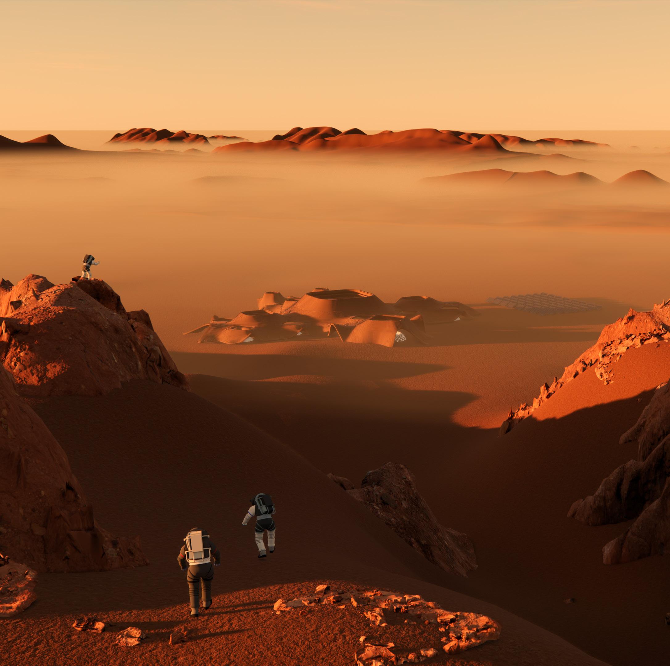 A render showing the view of the Mars desert research facility from the fossil rock mountains of the Mleiha desert located in Sharjah U.A.E

Major motorways
Secondary roads
Access to the site is granted via a existing sand road
The site has prominent terrain features with a contour interval of 50m close the Fossil Rock relief
Protected natural area
Military base
Residential zone

THE SITE
The site is relatively remote with settlements popping up only within a 3km radius of the proposed site boundary
The 3km radius area immediately surrounding the site has sparse density with low lying building masses
SOLAR
The site is left bare and open to the harsh desert sun all throughout the year with minimal shading
The location of the fossil rock formations provides scenic Martian like views perfect for a simulation site
WIND ANALYSIS
The program composition of the proposed Mars Analogue Science Centre


In this diagram, the solid lines indicate that the construction method in question addresses the constraint very well and a dashed line indicates that the issue is not addressed very well. The form is obtained by analysing the constraints posed

The end of stage - 1 of the form exploration exercise was marked by the selection of the double shell and pod construction techniques. The idea was to combine the two to make the most of their benefits. Therefore, the Centre itself would be composed of a protective exterior shell with deployable pods located within the protected space.
Stage - II was focused on determining the ideal shape of the habitats and their construction methodology. This was done by filtering the most adopted building shapes with high priority constraints
This diagram showcases the comparative analysis between the four construction methods; weighing up the benefits of each against the other. Ultimately the double shell and pods seemed to have the most benefits
With the data gathered from the previous two stages the form exploration began with various iterations exhausted unit the final forms were finalised with the area matrix
 STAGE - I
STAGE





The centre is divided into 3 zones as per the use case they are the Research zone, Education zone and the Administration zone. The research zone reserved for the scientists and astronauts. This area provides the facilities to perform tests, conduct studies and simulate Mars missions. It consists of the habitat pod, the farms, the research offices and labs. The education zone is reserved for the public; a place where the professionals can share and pass the knowledge down to the community through spaces such as the events pod, the exhibition pod and workshop pods.


The administration zone is reserved for private companies who have vested interest in space exploration and Mars colonization. This area consists of rentable office pods arranged around community gardens or bio pods. At the centre of these 3 zones sits the main bio pod which serves as the interconnection between the 3 zones. The bio domes allow for people to connect, gather and further bolster the trickle down effect of knowledge. These domes have hydroponic gardens scaling up their walls with spiral ramp providing access and views to each garden level.

Essentially an ETFE panel that’s filled with running water to ensure light passage & radiation protection at the same time

Piping systems that run cold or hot water through the interior shell and floor thus ensuring temperature control within the Hab
Achieved through the integration of a winding 3D printed staircase that sits in between the inner and outer shell
This membrane helps maintain the pressure within the pod and is deployed on-site. Its folded and brought in one piece.
Provides structural support for the inner floor plates and provides cavities for the piping. The shell is completely 3D printed

A series of clamp foundation pierce into the ground. This foundation doesn’t require much digging to take place.
Holds the ETFE membrane in place. Basically serving as an exoskeleton. Its 3D printed but is flanked with openings for views.
Allows for multiple uses to take place within a single space. They have different uses on either side and can be moved around.
The Habitat Pod regulates interior temperatures via a network of pipes that pass through the internal shell and floors. These pipes run hot or cold water through the internal skin thus cooling the interior air via convection and thermal transfer. The are another set of pipes which also help transfer waste water to the recycling unit located in the ground floor.

The exterior shell tethers and holds the internal ETFE membrane in place via cables. This helps prevent energy wastage when it comes to pressurising the hab. The hab has cut outs on the floor to allow for light to reach all parts of the hab. The skylight at the top is made using a water filled ETFE panel and protective glass covering. The water helps filter out UV radiation whilst allowing light in


 Entry/Storage Floor


The exterior and interior shell of the habitat pods are 3D printed with same material used for the exterior protective shell with the only difference being the thickness of the printed walls. Since the pods were situated in a "Cave" they couldn’t be so closed off and should allow maximum light to enter into the interior spaces. There was also the concern of material efficiency and structural support as well. Hence the shell adopts a distorted voronoi pattern to achieve a high level of porosity for light whilst being sturdy and using less material
The portable and movable bed/workstation allows for varied uses on the upper floor. Even the washroom is designed to be a transportable unit that can deployed easily. The station itself is not movable


Farms are situated in between the research pods for close adjacency. They have line of crops that are taken care of by a robotic arm. Humidifier units are also provided
Smaller Pods such as the workshop and Research office Pods can be fabricated using an inflatable dome which can be folded, packaged, and brought on-site easily.
EVENTS POD


 Consists of a central stage around which the stepped seating is arranged. The bottom portion of the seating units are used for support spaces such as green rooms, washrooms, storage, changing rooms etc in order to save space
A shot of the Events Pod


The Exhibition, Lab and Events Pods share similar fabrication techniques and hence a similar architectural language. Given that these are large-span spaces the exoskeleton design had to be robust yet material efficient. Hence it takes the shape of a 3D printed cross lattice dome that holds the pressure-containing ETFE membranes in place. The layout of the exhibition pod is centered around a skylit exhibition space that’s exposed to the outdoor conditions which usually contains the big exhibit. The rest of the exhibits revolve around this
They have an architectural language similar to that of the Research Habitation Pods. The difference is that it’s a single-shell system with a membrane layer as opposed to a double-shell system. The exterior shell is designed in a manner to provides adequate structural support whilst maximizing views to the surrounding region. The interiors of the office follows an open plan layout when it comes to the work areas themselves. The only stationary units are the washrooms, storage, executive unit and a meeting room with a central meeting space
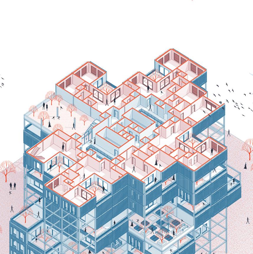


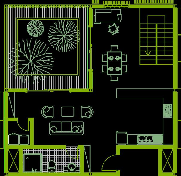
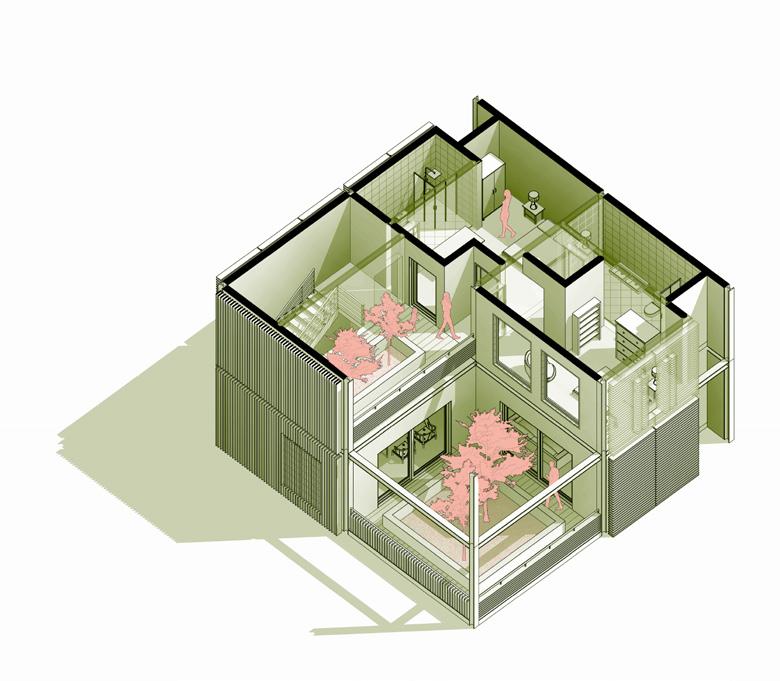
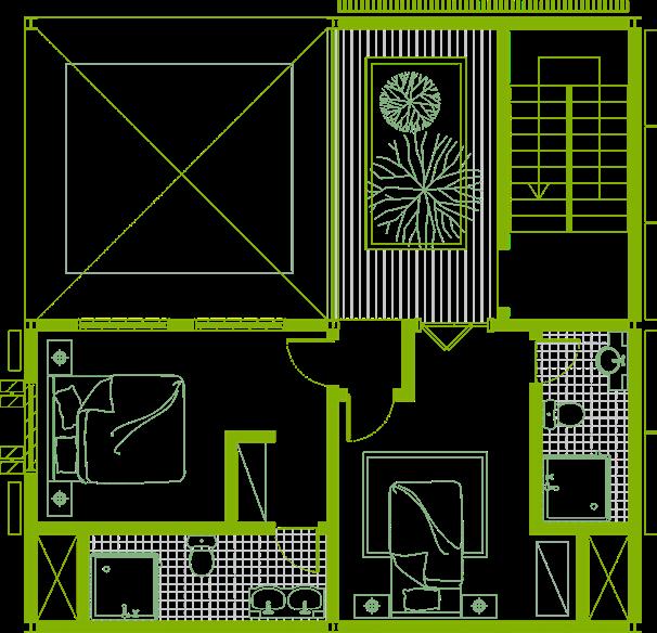
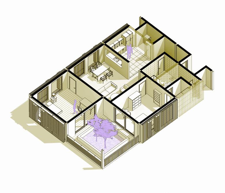
The brief stipulated the creation of a dense social housing complex within the periphery of the discovery gardens residential zone in Dubai. The main intent behind the design proposal was to create a social housing scheme that satisfied the client, the user, and the architect by creating modular and repetitive units that could be arranged in any fashion to create unique floor plates and ultimately diverse building blocks. The units, although repetitive, did allow for diversity through their nature of expandability as well as the provision of large free terraces or "backyards" that could set the stage for self-expression from each resident. The expandable nature of the unit ensured that the apartment grew with its residents hence cementing the idea of home.
Project Type: Academic (2021)


Built up Area: 112,000 sqm
Location: Discovery Gardens, Dubai, U.A.E
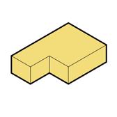
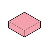
THE MODULES

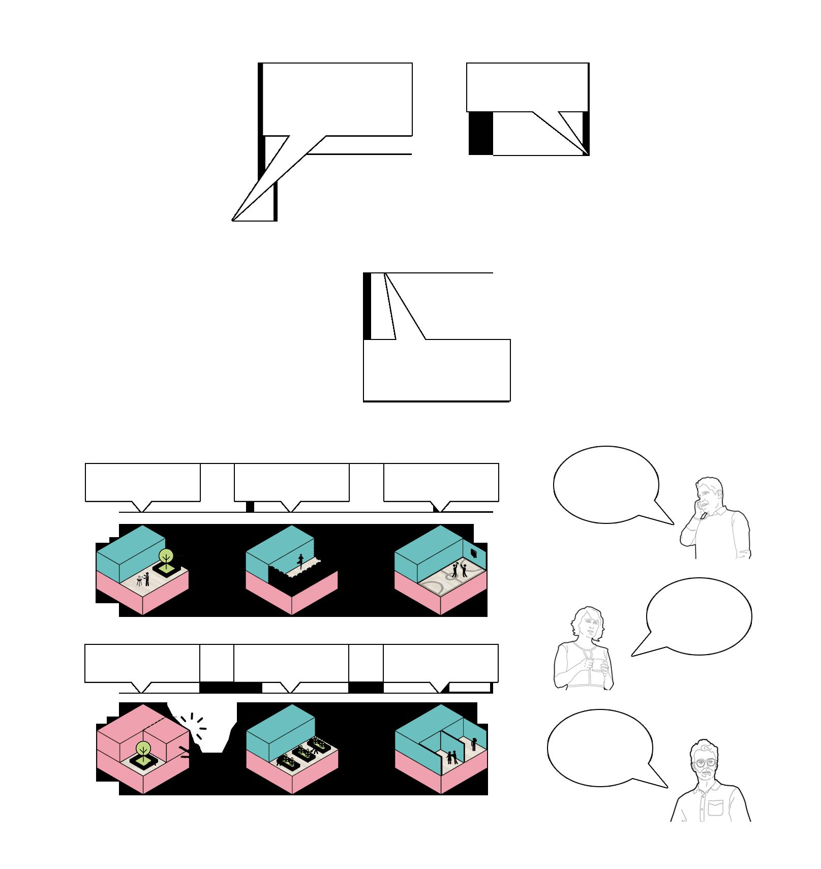
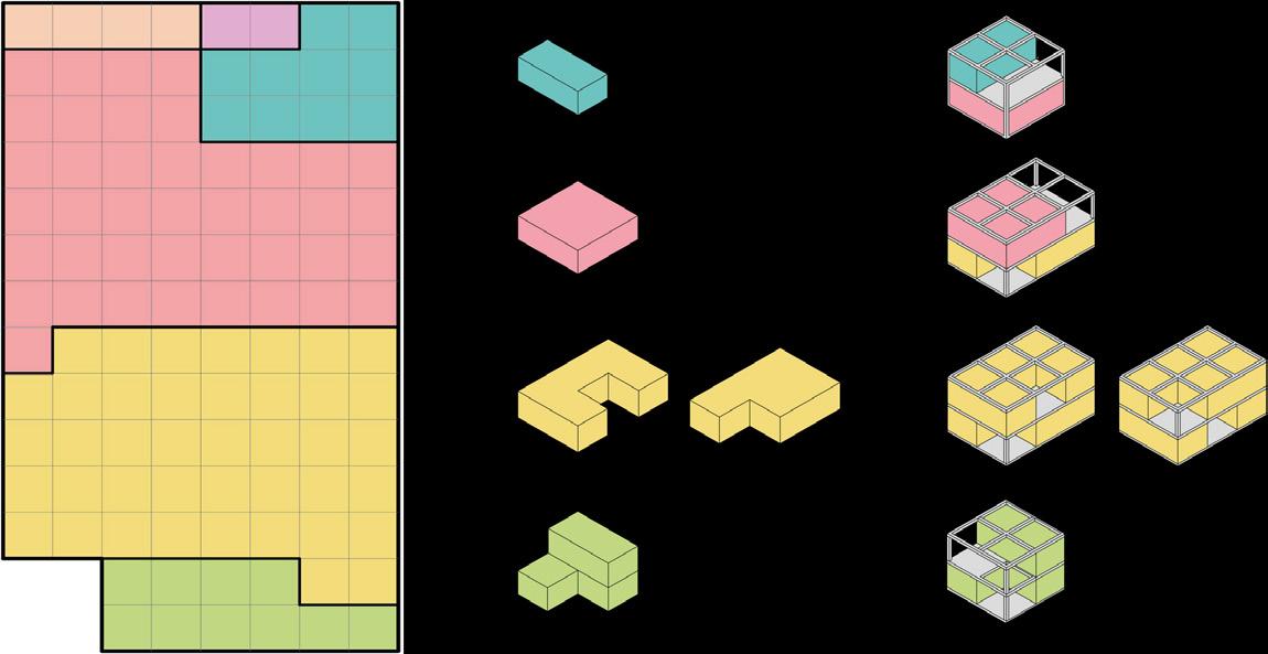
There was a need to provide large free terraces to the users without the terrace eating up the rented out space
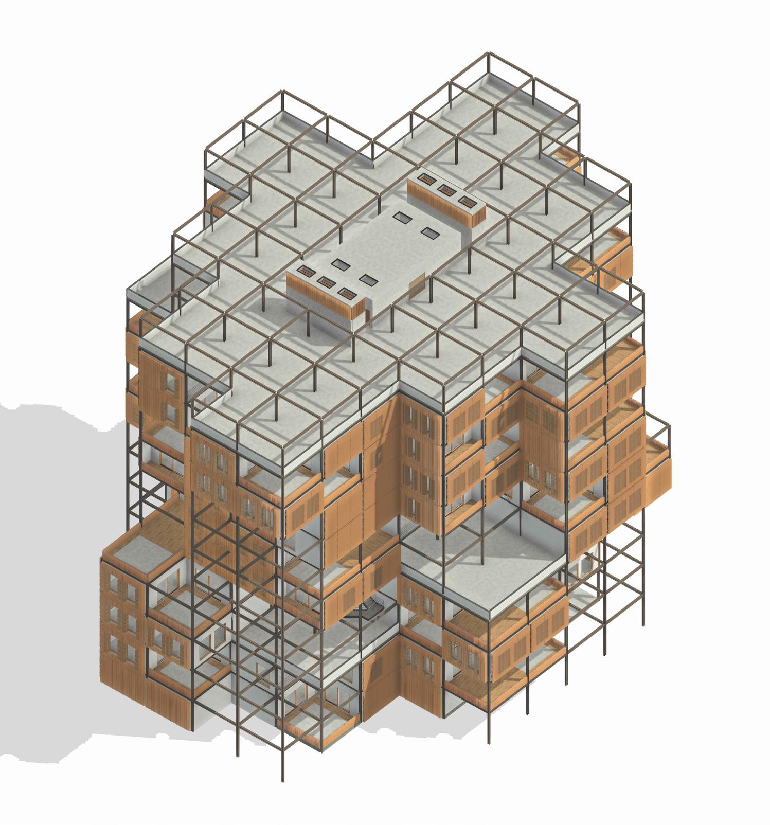
The module is stacked one upon each other to make building fabrication easier
The top modules are exchanged with each other to create a prominent area difference between top and bottom.

FREE TERRACES !
This allows for creation a large terraces due to the area difference which acts a backyard for each module
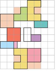
50 SQM STUDIO 100 SQM 1BHKVARIATION AT APARTMENT FLOOR LEVELS.
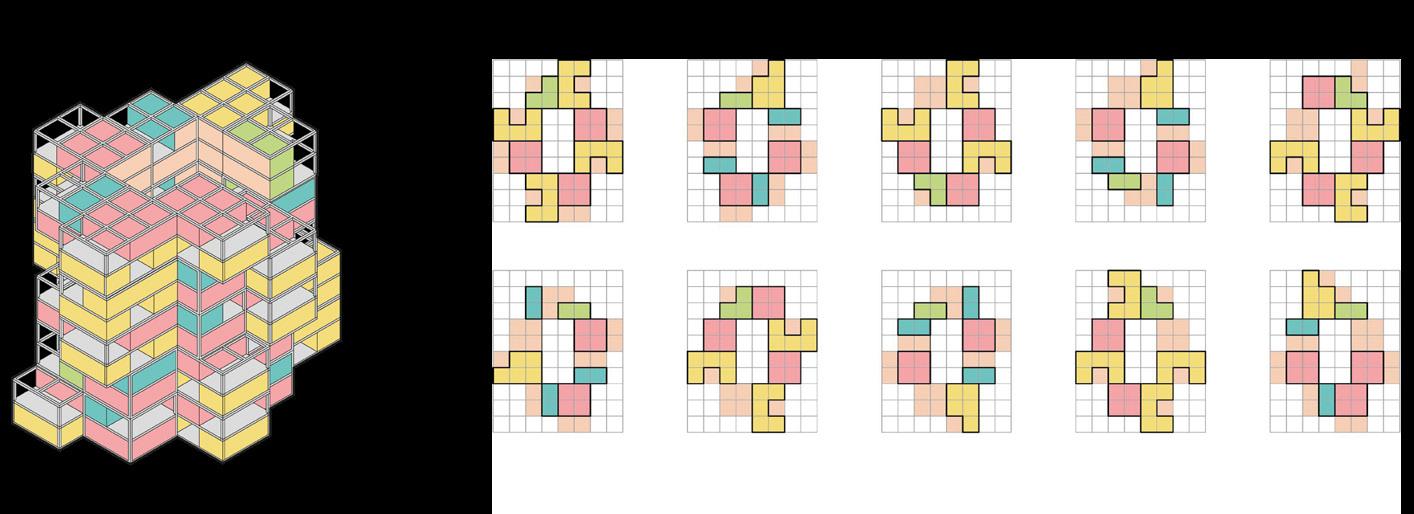
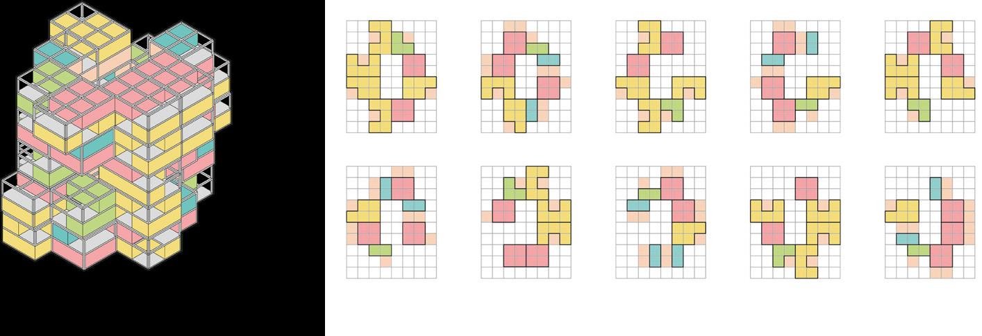
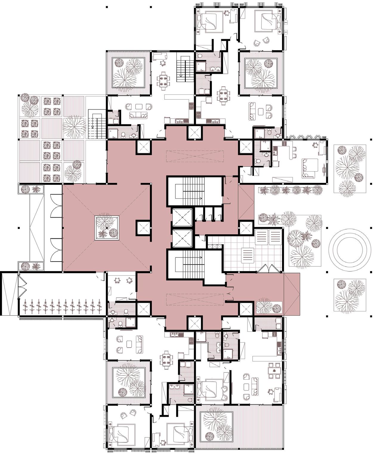
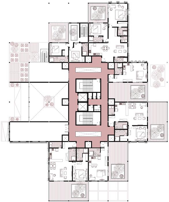
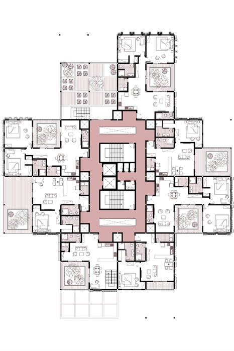
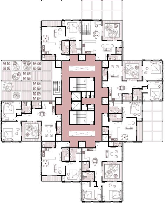
The new modules are arranged at every floor to ensure that no two floors are alike. This ensures variation and uniqueness to a usually repetitive floor plan.

VARIATION AT BUILDING SCALE.
The stacking creates varied buildings using repetitive modules.
STACKING FOR VIEWS + LIGHT + VENTILATION.
These floor plates are then arranged to ensure the provision of free terraces thus allowing for good visibility,
THE CLIENT


Modular & Repetitive apartment?
Great! Cheaper to fabricate!
Large terraces and expandable apartments?
Love it !
THE USER ARCHITECT

Non monotonous buildings with a distinctive architectural identity !
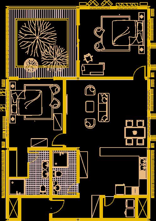
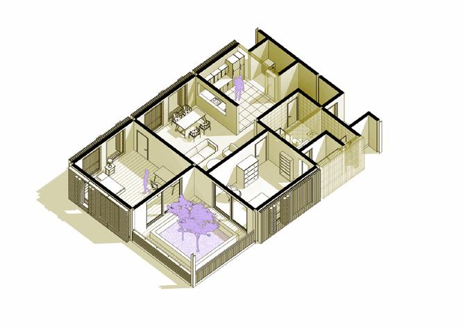
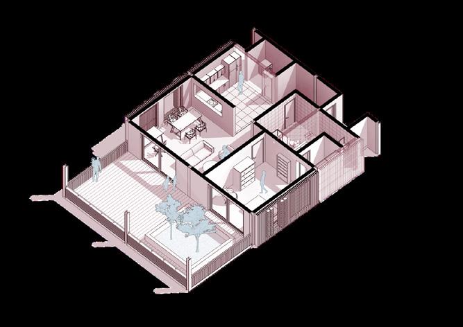
 The standard Terrace mode includes wide spaces and vegetation.
The terraces can be converted to introverted terraces for privacy.
Terraces can be converted into minature play spaces for the kids.
The terraces can be used up for expansion of the apartment itself.
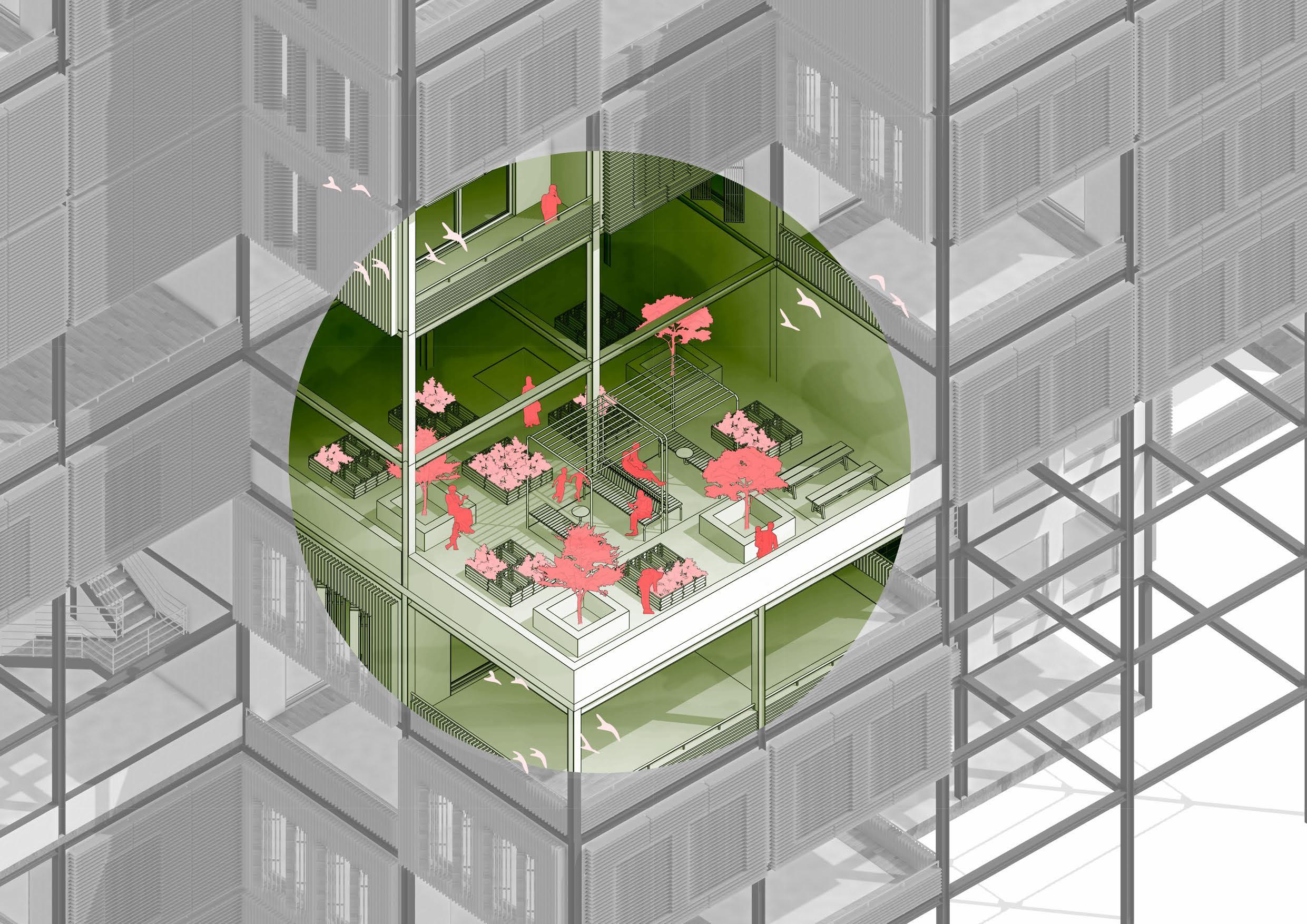
The terraces can be converted into a makeshift urban garden space.
The large terraces can be further subdivided for privacy among users




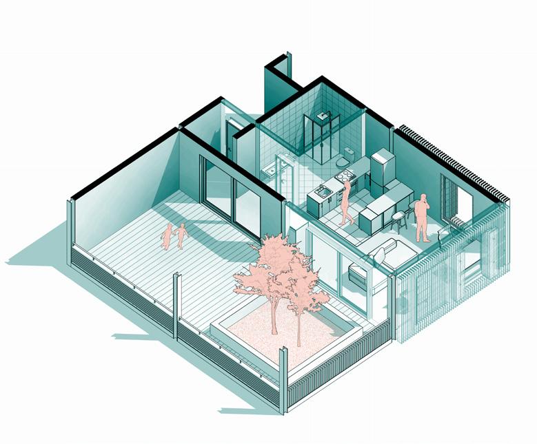


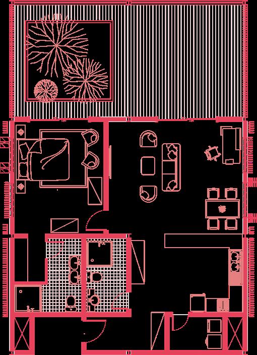


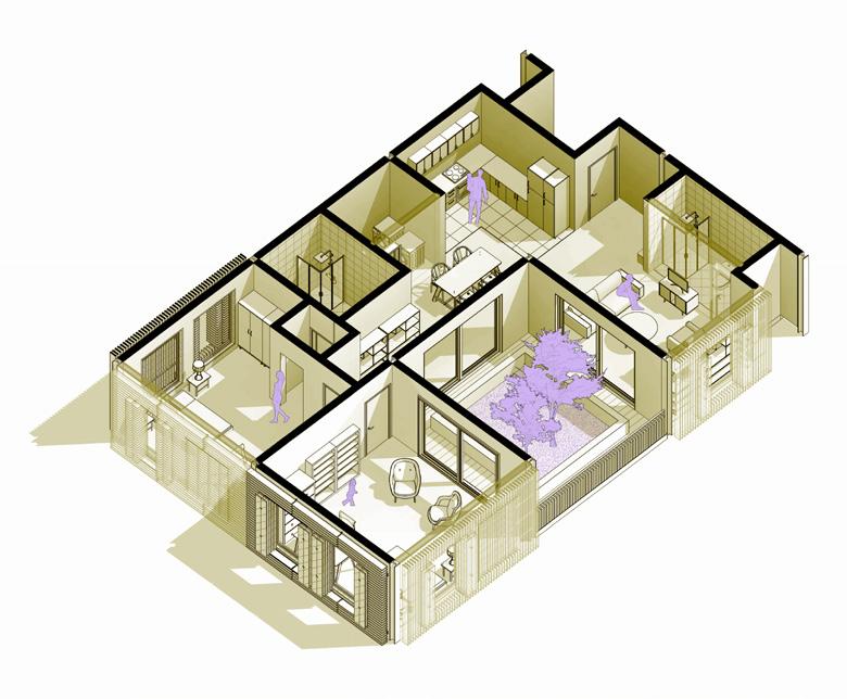


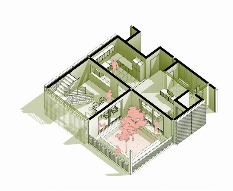














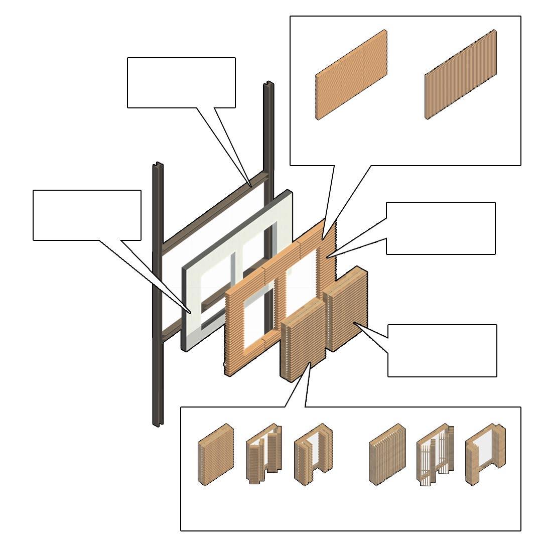
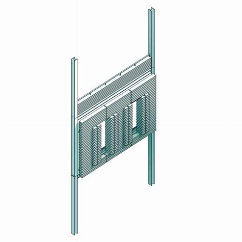
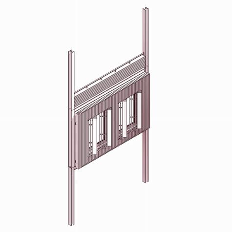
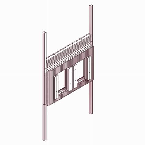
PREFAB EXTERIOR WALLS
STRUCTURAL STEEL FRAMING
N/S
The void spaces become leisure at these smaller office
E/W


The void spaces become leisure at these smaller office
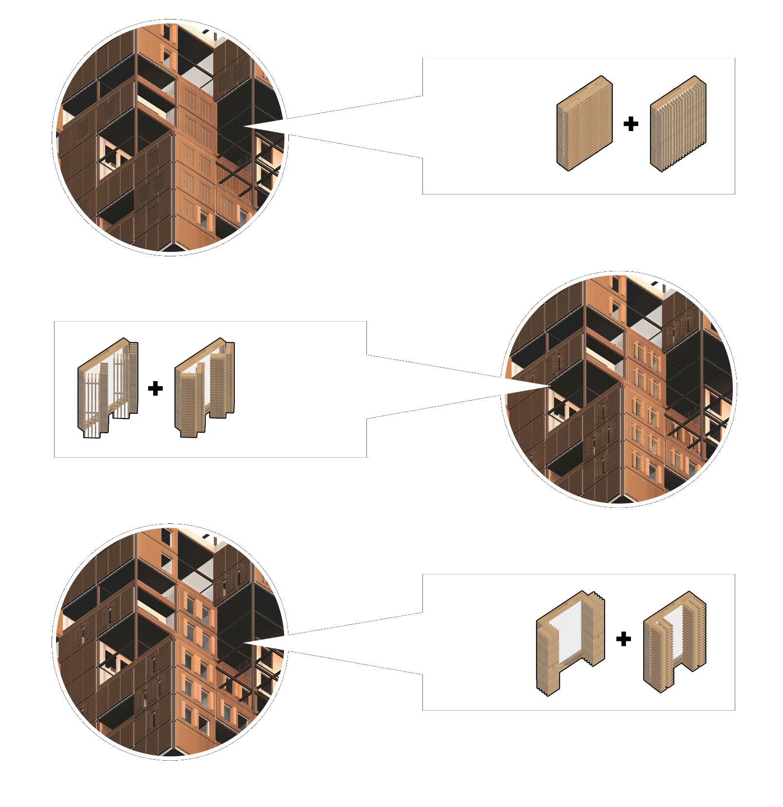
LOUVERED DOUBLE FACADE
AUTOMATED LOUVEREDWINDOW


The void spaces become leisure at these smaller office
The void spaces become leisure at these smaller office
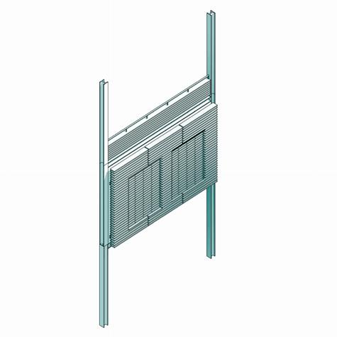
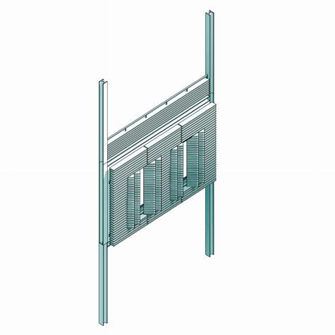
PARTIAL SUN EXPOSURE MODE
MAXIMUM SUN EXPOSURE MODE
INDIRECT SUN EXPOSURE MODE








COMMUNITY GARDENS FOR EVERY TWO FLOORS!



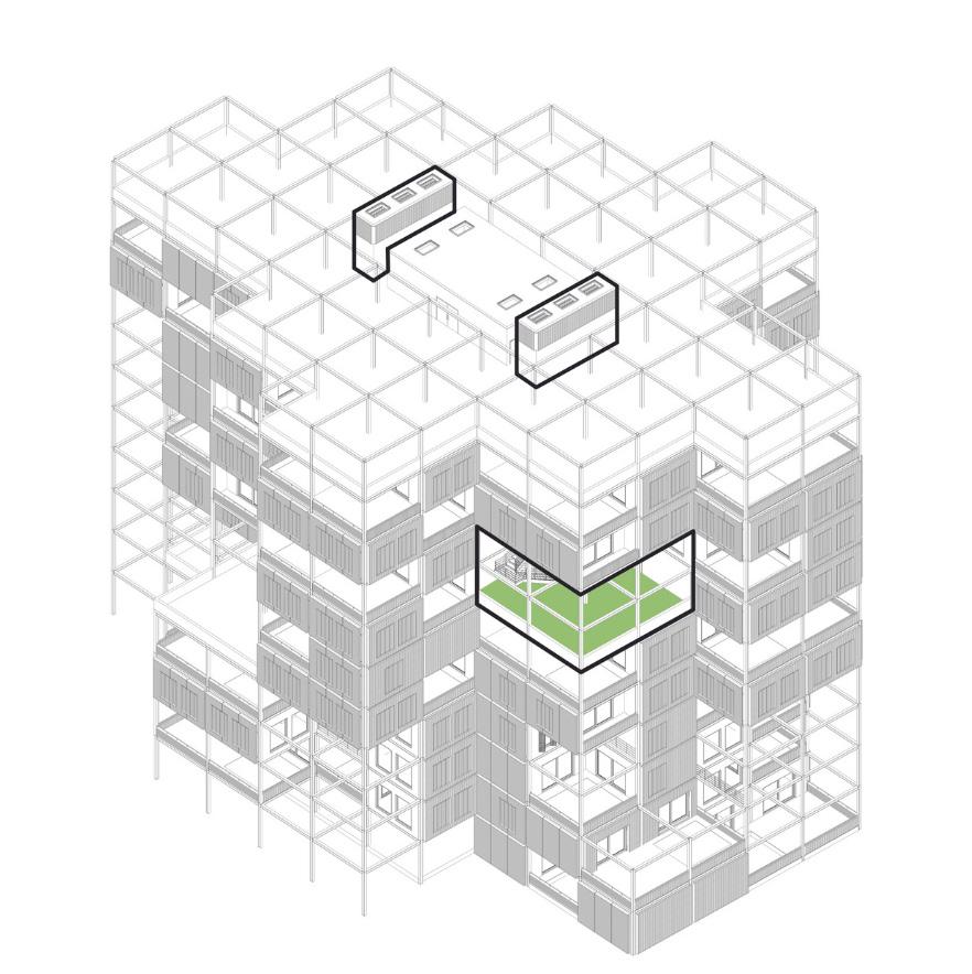


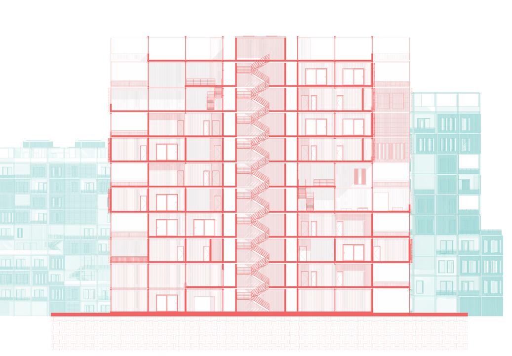
The tops of wind towers heat up, causing a stack effect. Heat is able to rise to the top of the wind towers and expel naturally, which in turn pulls the surrounding air through the voids to cool the inner circulation spaces naturally.

The building has voids cut through the facade and into the building interiors. Located on every elevation of the building, these voids double as communal terraces, allowing efficient capture of prevailing winds to ventilate and cool spaces naturally.


These voids also serve as large light shelves bouncing the sunlight into the interior circulations spaces. Add to that the natural light obtained from the skylights on the roof ensures that the interior corridors are always day lit.






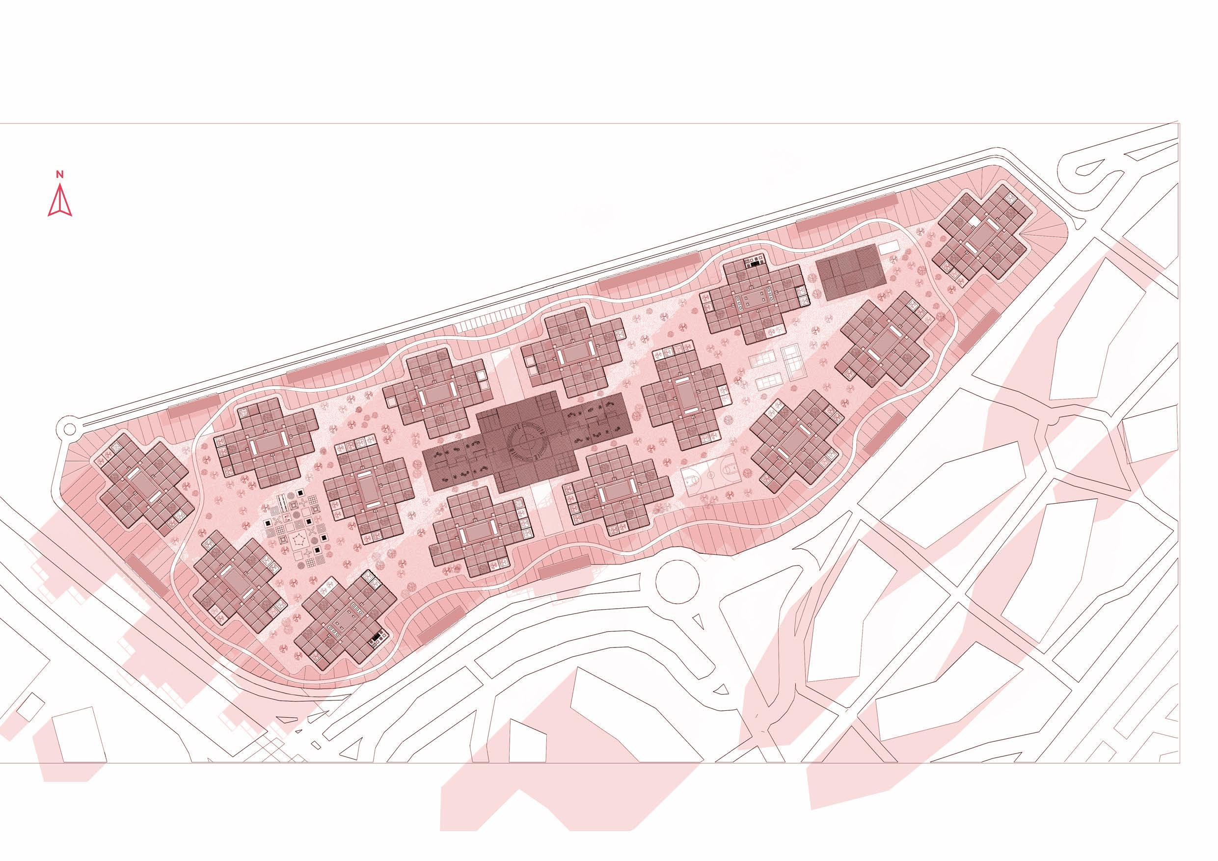
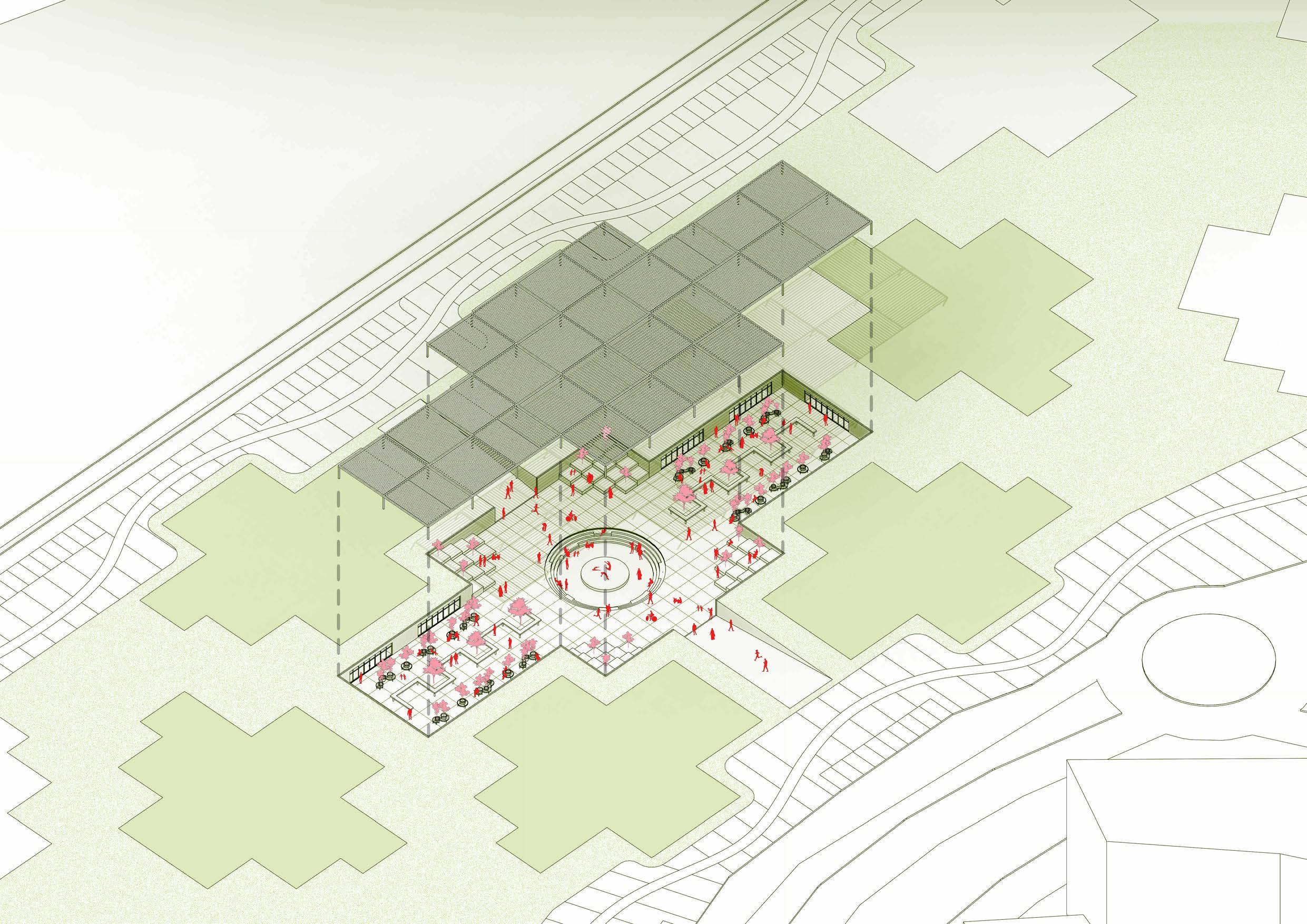
RUNNING TRACK + WALKWAY CHILDREN’S PLAY AREA



 TENNIS + VOLLEYBALL COURT
BASKETBALL COURT


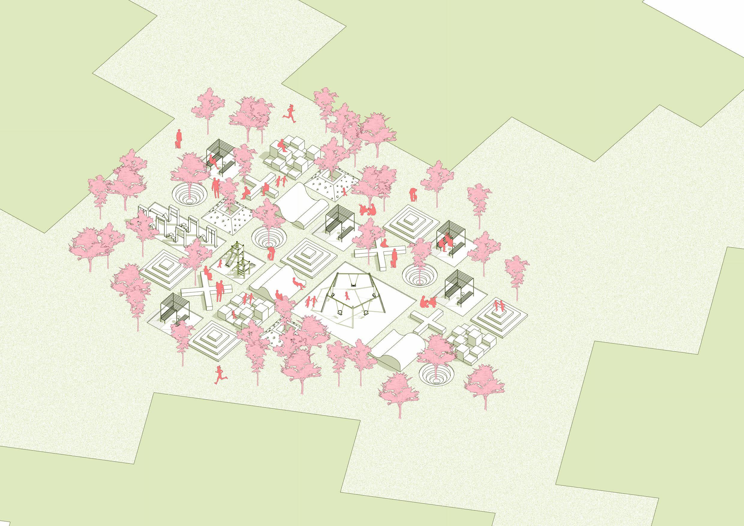
The children’s play area of the residential complex follows a grid of playful and interactive landscapes



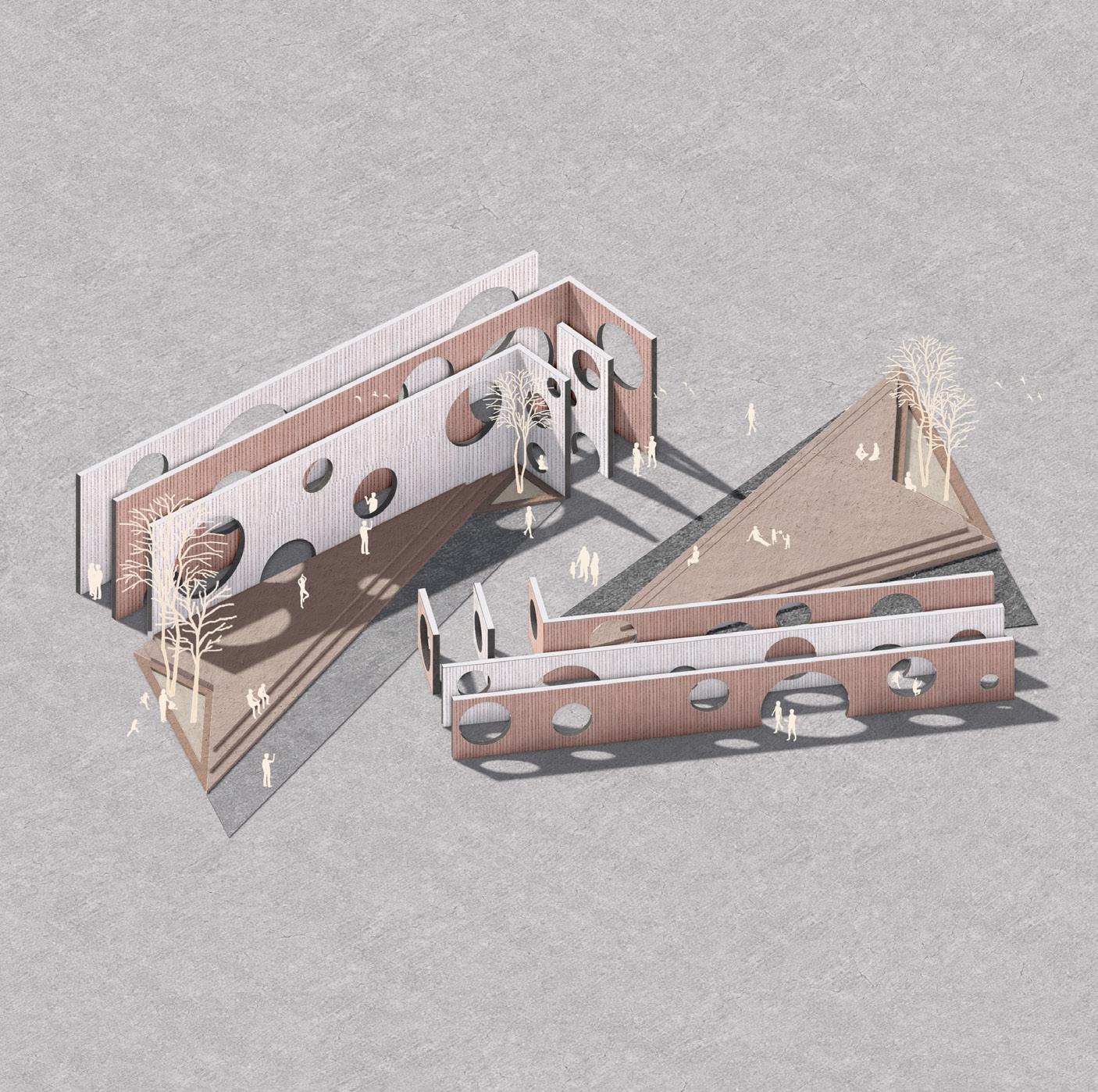



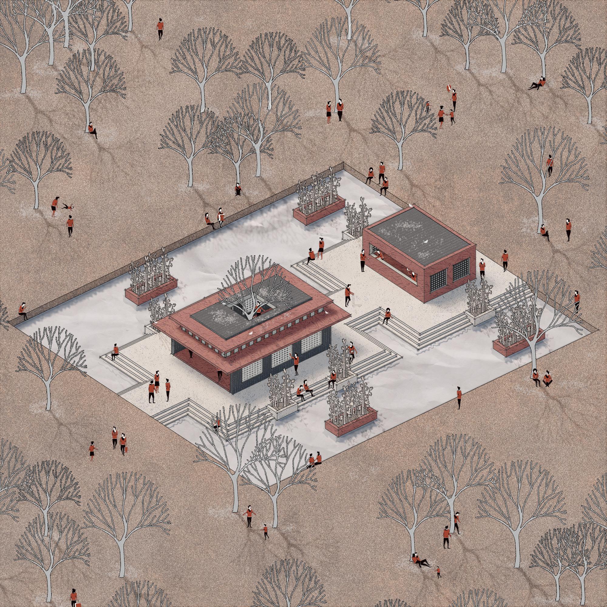
A post digital render of my early academic design work made as part of my instagram page called arch.genic.


