“Tree of Life” Institute
Studio 3.2. Anastasia Marinescu Atelier CPU[ai]

3.1 RECAP
The 3.1 STUDIO project delivered an initial proposal of the design. The primary creative drive constituted of incorporating green environments on site to connect the community with nature while focusing at the same time on the users’ general state of wellbeing (including areas for mental health and physiotherapy).The proposal consisted of a building with two levels, offering unobstructed views of the surrounding at the top floor. Taking an analogue approach in the previous studio offered me a better understanding of the site’s dimensions and challenges and finding solutions to overcome them.
The primary design with its qualities showcased through drawings presents numerous complications from structural strategies to environmental implications.
STRUCTURAL ANALYSIS: improvement of primary structure with further analysis on supporting schemes for the cantilevers, research of cladding systems to lower solar gains.
ZERO CARBON FUTURES MATERIALITY: additional research on materials for a sustainable design proposal focusing on thermal comfort and environmental impacts.
INSTITUTES’ IDENTITY: redesigning of buildings’ tree style centre column according to structural applicability

LANDSCAPE DEVELOPMENT: integrating a new approach to create a unique ecosystem for the design.
ENVIRONMENTAL STRATEGIES: further development of water collection and reutilisation systems, inclusion of green roof and photovoltaic panels to lower the carbon footprint and environmental impact.
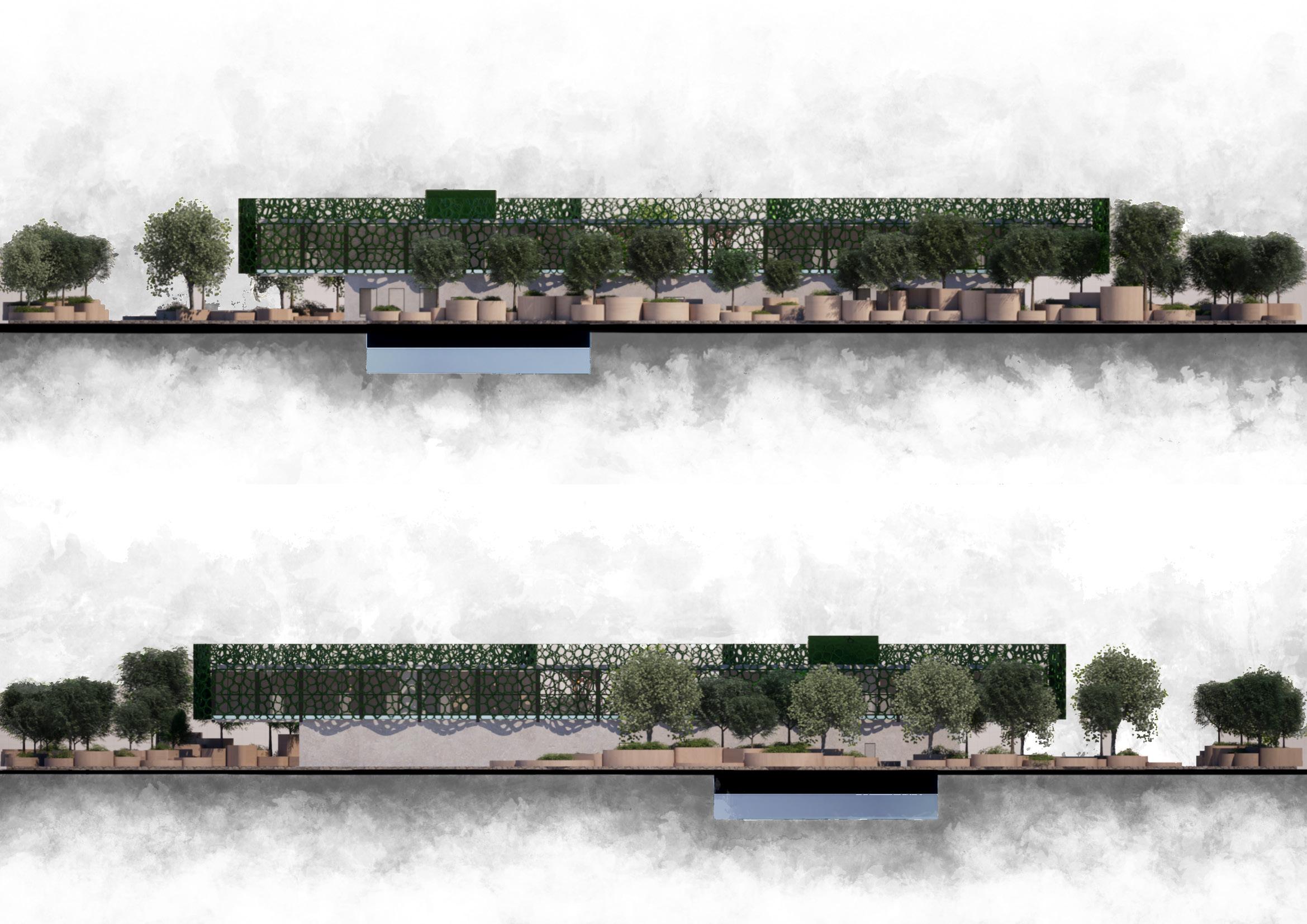
Initial building elevations at 1:200 with first structural proposal
The Sectioned Two Point Perspectives aims to depict the spatial relationship and continuity between the interior and the exterior.
“Tree of Life” philosophy symbolises life, growth, connection, and unity by representing how everything in the universe is interconnected and how all forms are rooted in the same essence. In the context of the built environment, the philosophy merges the natural and human-made environments in a harmonious and sustainable way. The proposal intents to strengthen the bond between nature, humans, and their well-being by following the philosophy’s principles through a generative and biophilic design strategy.
The “Tree of Life” Institute finds itself in the centre of Manchester’s student community. It pursues the journey of integrating biodiversity while focusing on the individuals’ general state of well-being. Starting from an analytical approach, my design develops into a sanctuary boosting connectivity between users, environment, and architecture. The Institute preserves a linear character empowering the interconnection of programmes through vegetation.
The future analysis in this part of studio aims to further develop the programme throughout the building. By modifying the room positions and dimensions, The Institute will deliver its intentions of integrating vegetation with physiotherapy, mental health, and study spaces. By incorporating study areas throughout the design, students are able to directly interact with professionals and patients and further develop their skills.
In studio 3.2 I intent to improve the structural character of The Institute. In the previous proposal the design lacked derivability on terms of structural support. In this part I would like to focus on constructability of the primary structure and what techniques are required to deliver the cantilevered areas. I will also focus on developing the building’s identity through structural design while engaging with sustainable strategies for delivering a project with minimal impact on the surrounding environment.
MuCEM MUSEUM MARSEILLE - RUDY RICCIOTTI
The MuCEM Museum by Rudy Ricciotti is renowned for its striking façade systems, innovative materiality, and connection with the Mediterranean Sea. The architect employed a unique façade system by playing with filigree concrete panels to generate various patterns. The patterns aim to improve the overall energy efficiency of the building by providing shading and filtering natural lightning thus lowering the solar gains. Rudy Ricciotti to deliver the unique character of the museum used a ultra-high performance fibre-reinforced concrete (UHPFRC), a material made of sand, cement, water and steel with high strength and durability allowing thinner and lighter structural elements. The façade is formed of prefabricated panels allowing precise manufacturing and faster construction. Overall the MuCEM Museum presents a visually captivating and functional façade which lights up during the night to boost its direct connection with the sea.
 The diagrams on this page show the connection between the organic facade and the concrete columns, and the relationship between the facade and the other structural elements
VORONOI FACADE DEVELOPMENT
VORONOI DIAGRAMS are mathematical representations that divide given areas into regions based on proximity to a set of points. The diagrams have a significant application in various fields including computer science, biology, physics, and geography. In terms of biology, Voronoi Diagrams are used to analyse the arrangement of cells in tissues both human (and organs) and plants. These diagrams play a key role in understanding the spatial organisation of cells and providing valuable insights of biological processes at cellular levels. Voronoi Patterns have a vast implication in architecture too and are frequently used for cladding systems or design elements. The diagrams below depict Voronoi Patterns in human and plant cells and they show the similarity between their structure and presentation.
The script below presents the Grasshopper functions required to generate Voronoi diagrams on rectangular surfaces by including the number of attractor points. To reproduce the textures from the tissue Voronoi diagrams the script includes the fillet function allowing the elements to be curved.
Grasshopper Script used for generating the facade
Voronoi Façade iterations testing various set numbers and the geometry distribution on the building. Similarly with MuCEM Museum, the facade created using Voronoi aims to provide shading, filter natural lightning and improve the overall energy efficiency.
 Human Neuronal Connections
Human Tissue Cells
Human Blood Veins Relation Human Red Blood Cells
Vegetal Multipllying Cells
Voronoi Diagrams generated by the script
ENVIRONMENTAL IMPACT
To better understand the requirements and environmental performances of the spaces designed on the top floor I tested multiple iterations of facades. The analysis helped in choosing the most optimum façade based on internal thermal comfort and solar gains throughout the year. The facades below were generated using the Voronoi function in Grasshopper. The tests were conducted using Grasshopper functions such as LadyBug and HoneyBee. Each result helped in choosing the right geometry for the cladding and the proposals were compared between themselves and with the fully glazed case. Prototypes tested based on the number of attraction points used in the Voronoi script
Test 1: HoneyBee
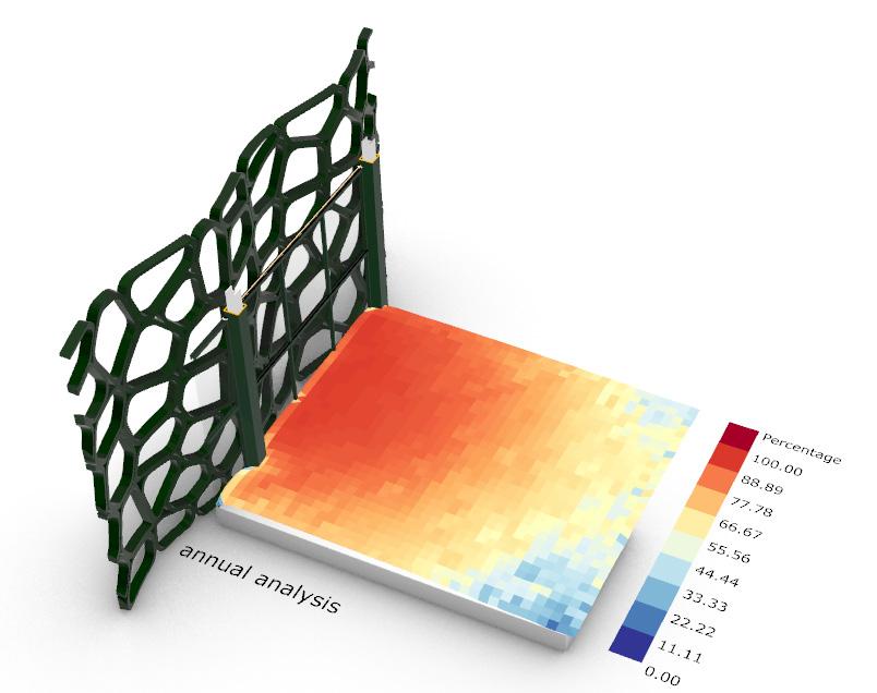
The diagrams present solar gain distribution on the floor, the percentage of solar gain for each part of the space and shaded areas annually. A higher percentage of direct sun indicates a great risk of overheating.


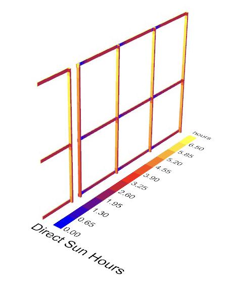


Test 2: LadyBug Winter
Diagrams show the quantity of direct sunlight during winter. Because of the surface’s curved character, the amount of sun hours is distributed differently for each prototype. A high amount of direct sun hours leads to passive heating generating thermal control with minimum mechanical ventilation.
Test 3: LadyBug Summer
This test takes the same approach as the previous one but during summer In this case high amount of direct sun on the façade results in overheating, thus leading to increased cooling loads and mechanical appliances with high energy consumption.
Conclusions
In this scenario the building is fully glazed with no protection to direct sunlight. This case as seen in the diagrams on the left side performance the worst compared with the other prototypes. The areas are prone to overheating and gaining massive amounts of solar energy throughout the whole year. Being fully glazed this case permits unobstructed views of the exterior and natural lightning all year round.
The first façade prototype bade on Voronoi is formed from 100 attractor points generating large geometries spread randomly on the given surface. Compared with the initial scenarios, this case lowers the overall solar gain of the slab and creates shadowed areas. During summer, the façade has the worst performance from all the prototypes, getting the most solar gains, thus requiring further mechanical ventilation. Contrary, this case one of the best performance during winter.
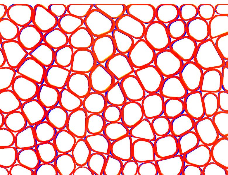


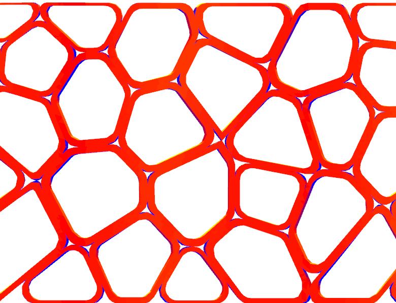


This iteration is formed of 2000 attractor points on the surface and showcases a better performance compared with the previous situation. The Voronoi 200 proposal sees a decrease in overall solar gains and generates more thermal comfort for the area. The testing shows a small increase in the amount of shadowed areas and increased direct sun hours during summer.




The Voronoi 3000 prototype is a further improvement of the previous case. The façade manages to significantly lower the quantity of thermal mass, having the most affected areas on a small segment near the glazing. During winter the façade has a lower performance gaining less direct sun thus minimising the effect of natural heating. On the other hand, in summer the façade efficiency is higher reducing the solar gain.
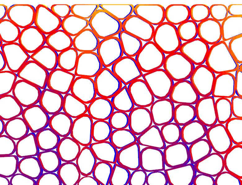
The last iteration includes the most geometries on the surface. The increased number of geometries resulted in smaller elements which lowered the amount of solar gain thus creating areas not affected by direct sun. This prototype has the overall best performance in all the test conducted. It aims to achieve thermal comfort during wintertime and lower as much as possible the need of air conditioning systems in summer. The pattern also creates intriguing shadows building up the

 Voronoi 1000
Voronoi 2000
Voronoi 3000
Voronoi 4000
Based on the environmental performance of the tested facades the most effective prototype for thermal comfort, solar gain and shadows control is the one depicted in figure 3.

COLUMN IDENTITY AND FUNCTIONALITY
Testing the identity of the central piece through analogue and digital techniques.
The exploded axonometry aims to depict the relationship between each structural element in the central interior garden space. The organic columns mimicking tree trunks provide users with a sense of a natural garden through architectural and structural planning. Integrating timber design elements for planting and seating enhances the biophilic design approach and creates an area that boosts biodiversity and connection between users and the environment

The initial proposal was for a central singular column located in the heart of the design. Due of the large spanning areas the analysis of new structural grids for load distribution was required.
Based on the diagrams above showcasing the structural grids and on the engaging discussions with structural engineers throughout the year, the most effective way to deliver my proposal was by incorporating four columns to evenly distribute the dead loads
The chosen columns have an intricate organic design created using parametric programmes. Their slim silhouettes require further support strategies and elements as seen in the detail sections and plans below
INTERIOR VIEW
Atrium space designed for interior garden with unobstructed views of the exterior thus generating the connection between the interior and exterior and offering natural lightning not only from the floor to ceiling glazing but also from the column openings. The area aims to further connect the users with nature by surrounding them with vegetation areas and allowing them to further develop the biodiversity of the space

MASTERPLAN INTERVENTION
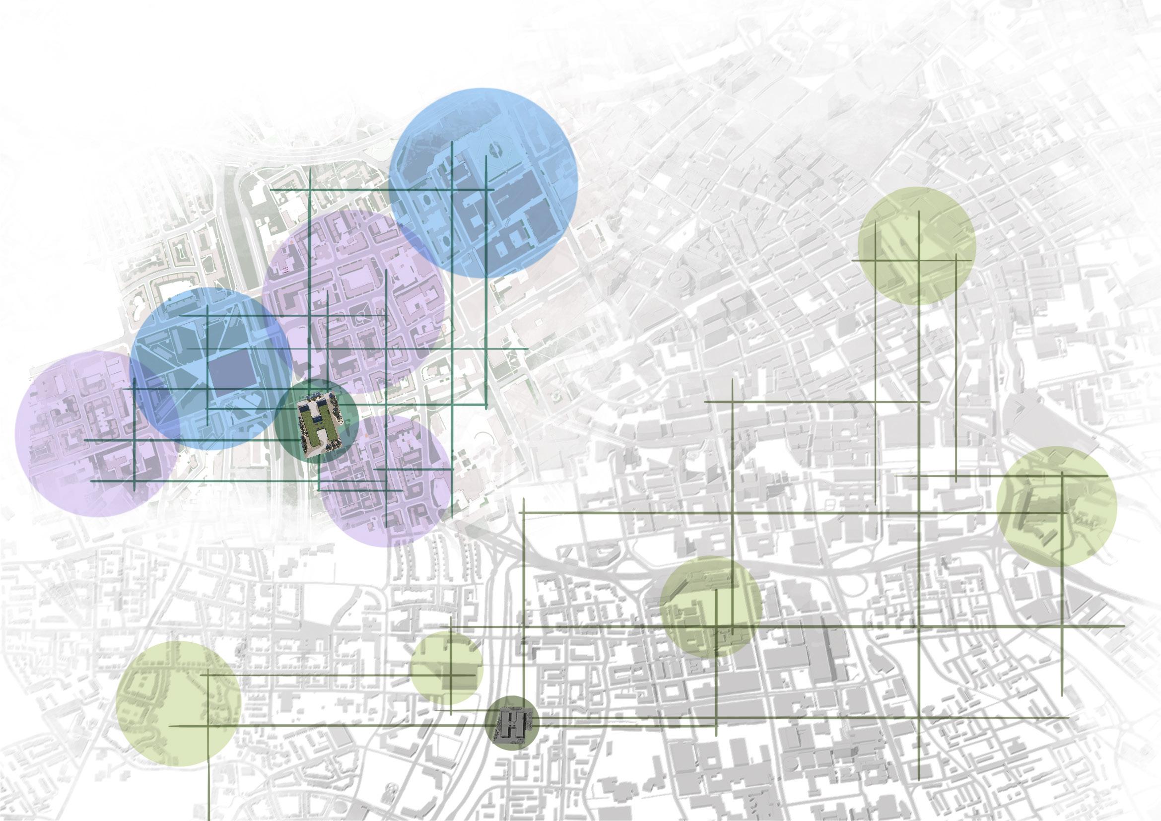
The “Tree of Life” Institute aims to connect and bring people together as well as to become an asset for the Hulme community. The project intents to create a connection between the two MMU Campuses (The Birley Centre and the MMU Main Campus). Located between the two campuses, The Institute creates an opportunity for students at different courses to interact in the study areas. Additionally, the project aims to bring green environments in Manchester’s centre. Following a biophilic approach of designing, the “Tree of Life” Institute boosts biodiversity and intents to become the unique community garden of the area.
Diagrams show Hulme Area and Manchester context
MMU Campus Locations
Residential Areas
“Tree of Life” Institute
Connections with the Institute
Green areas in Manchester
“Tree of Life” Institute
Connections with the Institute
LANDSCAPE INTERVENTION
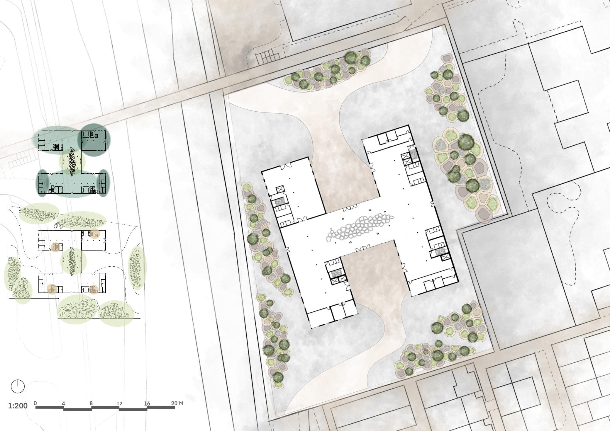
The landscape strategy focuses on generating multiple green spaces surrounding the building while creating more access points on the site conveyed in the green areas. This approach is accomplished by integrating circular timber structures designed for various purposes such as: tree planting, small vegetation with flowers and seating areas. To build up the character of the building each landscape element has different heights and geometries generated by Voronoi using Grasshopper.
 The diagrams below showcase the various purposes of the timber structures proposed for landscaping.
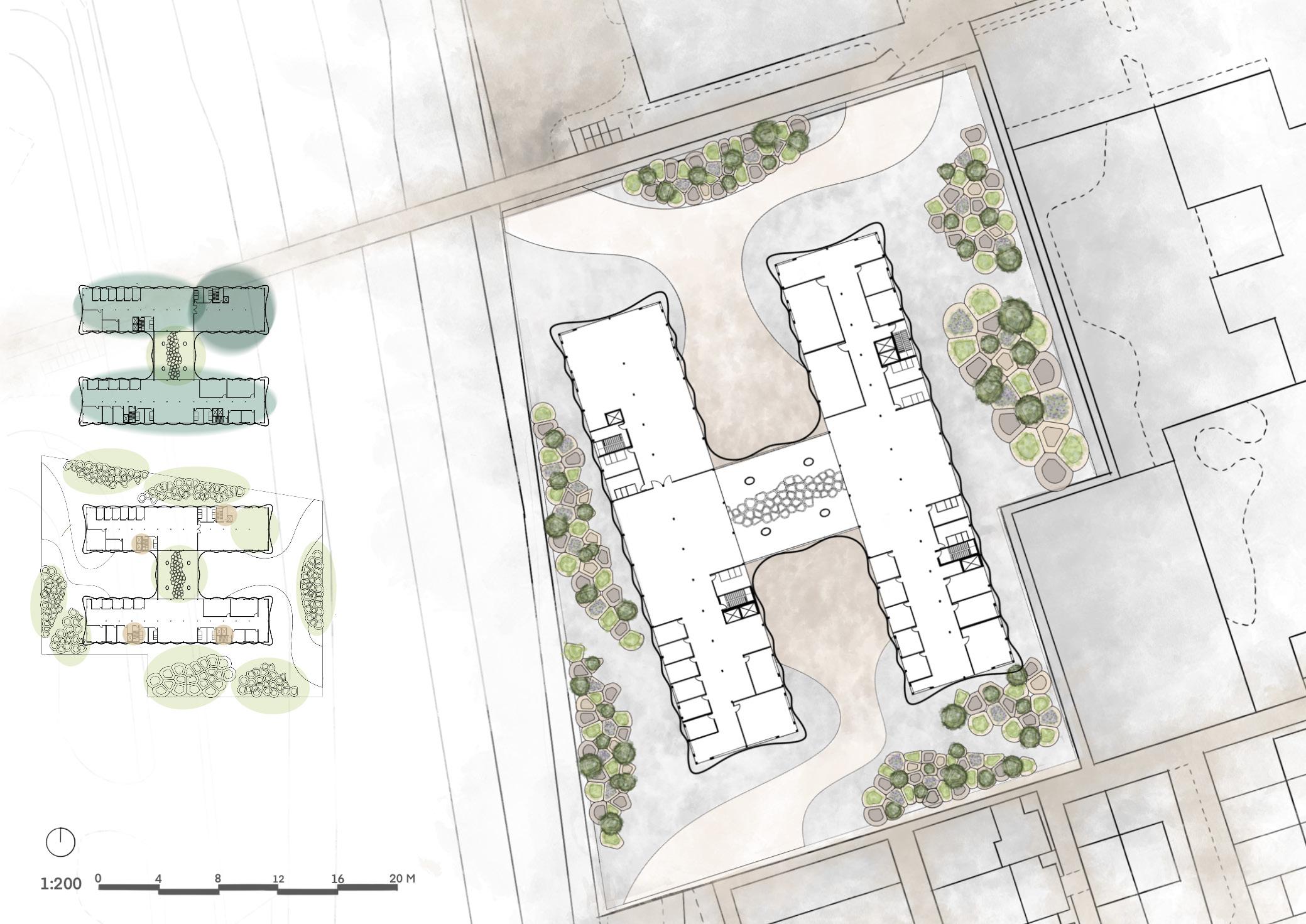
GROUND FLOOR GA PLAN
1. Group Study Area
2. Staff Spaces
3. Interior Garden
4. Reception and Waiting Area
5. Group Speech Therapy (10 people)
6. Individual Speech Therapy
7. Staff Resting Area
8. Staff Changing Rooms
9. Storage Spaces
Green Spaces
Circulation
Public Spaces
Private Spaces
1. 2.FIRST FLOOR GA PLAN
CONSTRUCTION SEQUENCE


The “Tree of Life” Institute takes the approach of minimal construction carbon emissions. Following the RIBA work plan, the concept tackles all the stages mentioned with more consideration in the initial steps for more analysis on the site conditions and structural strategies. The low impact on the environment is generated by having most of the structural elements prefabricated and transported on site. The primary structure of the building consists of the circulation shafts. the steel structure beams, columns, and trusses and the organic parametric columns connecting the two areas of the building. The diagrams below show the construction sequence of the Institute.

 1. Pouring the foundation and excavating the basement used for internal mechanical services.
2. Setting the structural circulation and elevators shafts
3. Including the primary structure of the building made of steel columns beams and trusses.
4. Adding the parametric designed columns to connect the two sides of the building.
5. Including the internal walls and floor finishes
6. Placing the roof and the glazing systems for each floor
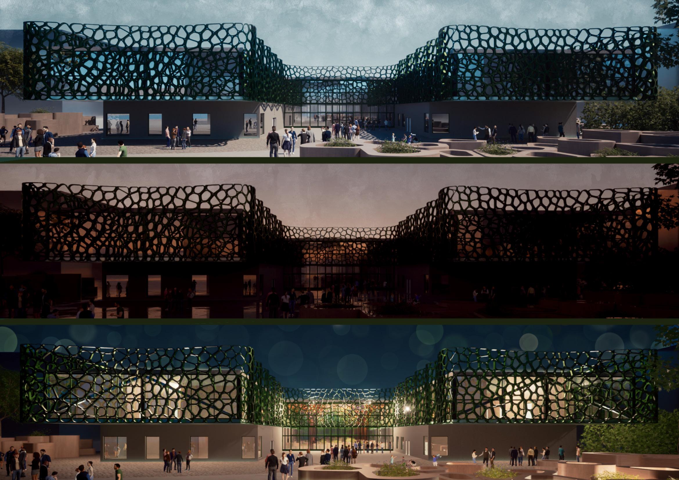
7. Assembling on site the prefabricated solar control façade and building up the identity of the building
8. Implementing the landscape strategy by adding the proposed timber elements designed for multipurpose usage: plantation or seating.
9. Planting the trees and medicinal shrubs aiming to develop the biodiversity of the site and contribute to the proposal’s character.
BUILDING REGULATIONS
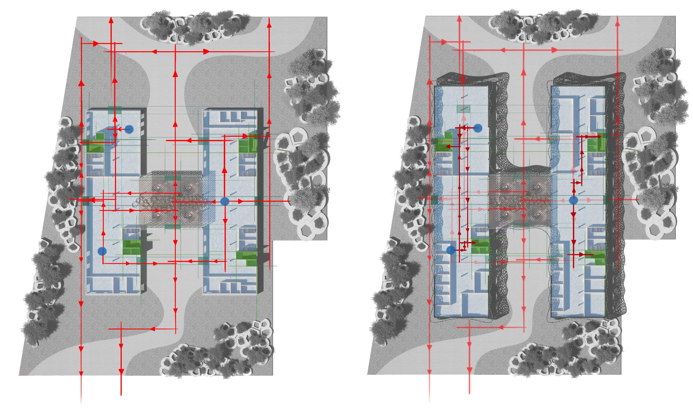
Under UK Building Regulations Part B, escape routes in non-dwelling buildings should be designed to ensure the safe and swift evacuation of individuals in case of emergency. The regulations state that the maximum distance from a point (with unobstructed views) to the closest exit should be maximum 18m The institute designed could be divided in four areas, each of them offering at least one exit. This decision was made to offer multiple exits for all the users. The diagrams below showcase each possible route a person could take to exit the building and the site. The circulation shafts were strategically positioned for optimal escape. Each circulation shaft throughout the building is placed near an exit. In the design of the circulation shafts fire resistant materials were used (such as concrete and, doors designed for fire protection) and the stairs have 1000mm width to accommodate as many users as possible. In the case of an emergency the main entrances of the building could be used as fire exits.
USERS’ EXPERIENCE
The programmatic areas of the institute are connected through the central atrium. The atrium is considered the heart of the institute and represents the main attraction where functionality meets vegetation and aesthetics. On the top floor the space is designed to enhance human interactions while offering unobstructed views of the structural character of the building.

USERS’ EXPERIENCE
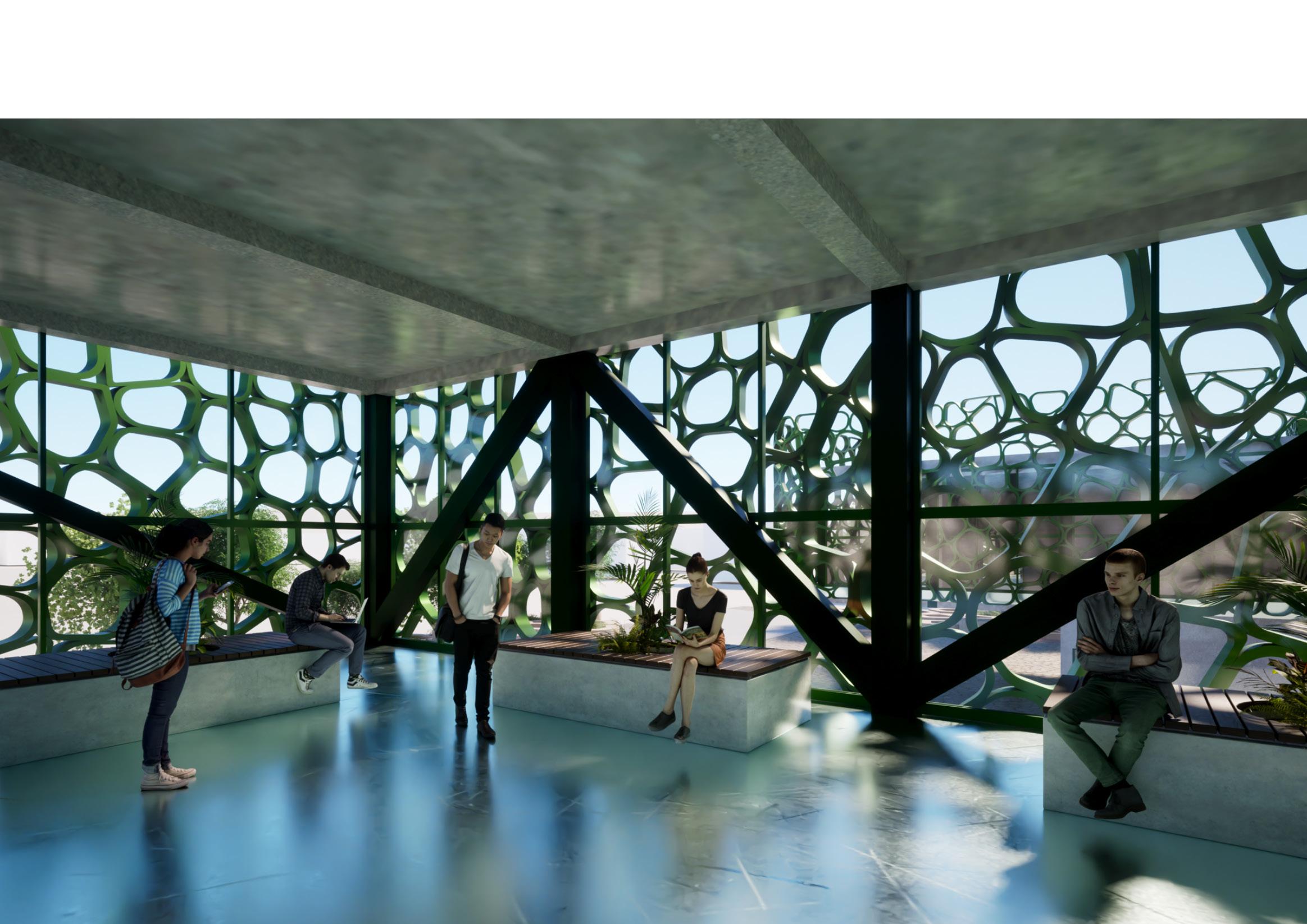
The study areas were designed to encourage engagement between students. The open space area is fully glazed and offers unrestricted views of the surrounding environment. The study area becomes a safe space for students to interact with their peers while learning in an environment surrounded by vegetation


CONNECTING USERS WITH THE ENVIRONMENT
Medical plants: lavander, chamomile
Following the “Tree of Life” philosophy the proposal aims to strengthen the bond between nature, humans, and their wellbeing. The landscape strategy proposed permits users to interact with the environment and help enhancing the biodiversity of the Institute. Community members are invited to take part in planting medicinal flowers and shrubs Diagram showing user helping the process of planting

MATERAIL SELECTION AND STRUCTURAL ANALYSIS
In 3.1 one of the main problems of the proposal was the steel structure that spans at and has cantilevers on each side. To find the right structure for my the areas. Based on the discussions I had with the trusses on the areas which are throughout the building.
The exploded axonometry on the right side of the page shows each layer of the building. The layers presented aim to offer a better understanding of the primary and secondary structural elements. From the axonometric view a better understanding of the connection of the layers and the materials used is offered.


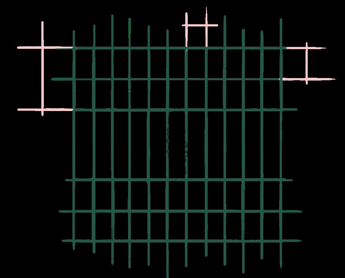
Based on the right structural elements for distributing the load vertically throughout the building, the structural grid of the concept was created. Having a linear building, the grid is overall symmetrical and permits a better understanding of the spaces and simultaneously helping in distributing the load.

When selecting the materials for my design proposal I focused on materials with long lifespans, low maintenance, high thermal conductivity, fire resistance and acoustic properties. Having the primary structure made of stainless steel and concrete, increased the environment impact of my building, thus by using sustainable materials and systems such as green roofs, adaptive façade, Celotex insulation, double glazing and fibre cement panels helped in reducing the carbon footprint. At the same time the building ‘s structural elements are prefabricated and brought on site thus minimising the CO2 emissions during the construction process.

Sustainability analysis on Fibre cement panels from EQUITONE and how the material performs compared with others.


The fibre cement façade panels from Equitone offer the visual effect of rough, unpolished concrete and have high sustainable properties.
SHS coated dark green with bolted plates used for assemblying the façade




 Key – Numbers represents the numbers on page 8 for the RIBA guide
 Grey water collection tanks
Rain-water collection and filter tanks
1. Acoustic barrier
1. Acoustic barrier
2. Green Roof Strategy
3. Operable Windows
4. Photovoltaic Solar Panels
Natural buffer for external noise sources Natural buffer for external noise sources Boosts internal natural ventilation and lightning
Produce electricty from natural sources reducing the need of mechanical services
5. Perforated Façade System Lowers solar gains, increases thermal comfort and creates shadding for overlit areas
6. Vegetation Release CO2, boosts oxygen production
7. Rainwater Cllection Internal reuse and irrigation systems 8. Rainwater Reuse Irrigation systems for external and internal vegetation
9. Greywater System Filtration systems for reusing water throughout the building
Noice reduction, stormwater management, insulation and biodiversity


 Facade 3D Printing Process


