2 minute read
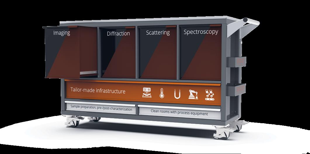
Imaging


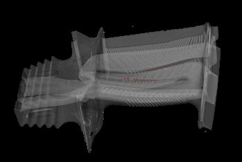
Neutron and Synchrotron CT –Two complementary non-destructive inspection methods
Continuous improvements in material properties and production processes in industry mean that more sophisticated analytic techniques are required. Imaging methods such as computed tomography (CT) provide a three-dimensional view of the interior of objects without destroying them. Neutron and synchrotron CT offer possibilities to examine samples with higher spatial resolution and high sample throughput in real time. The data thus obtained form the basis for further analysis options, as described on the right.
Technical details of neutron and synchrotron CT Selection of detailed information
Information
Field of view Spatial resolution Temporal resolution Energy range Wavelength Bandwidth Flux
Neutron CT
5 x 5 mm² – 400 x 400 mm² 8 – 150 µm 150 Hz in 2D 2.3 – 25 meV 1.8 – 6 Å 10 % ~ 107 – 108 cm–2 s–1
Synchrotron CT
0.3 x 0.4 mm² – 16.6 x 14 mm² 0.16 – 6.5 µm 20 Hz in 3D 8 – 45 keV 1.5 – 0.3 Å 0.02 % ~ 1014 cm–2 s–1
Imaging is used as a qualitative and quantitative measurement technique with the following analysis capabilities:
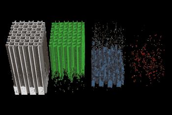

Material distribution analysis in 3D
– Visualization of the outer and inner structures and geometries of arbitrary and complex objects – Segmentation of the object into its individual components and materials
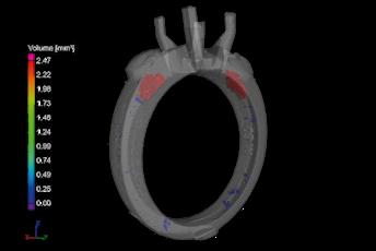
Defect and porosity analysis in 3D
– Visualization of pores, blowholes and inclusions inside arbitrary and complex objects – Quantitative information such as size, volume, shape and associated distributions – Determination of the total percentage of defects and porosity, and presentation of results in a histogram
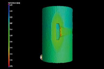
Wall thickness analysis in 3D
– Quantitative determination of the wall thicknesses of arbitrary and complex objects – Localization of areas with insufficient or excessive wall thicknesses or gaps
Nominal/actual comparison analysis in 3D
– Direct geometrical comparison of CT data with
CAD data of arbitrary and complex objects – Quantitative information regarding deviations in the dimensions of an object compared with its CAD drawing
Reverse Engineering
– Physical reconstruction of arbitrary and complex objects without knowledge of design data – Determination of external and internal object geometries – Creation of an STL file for subsequent reverse engineering to a CAD model


