Contents
Drawings

section number one


section number one
The proposed building is configured in a rectangular form with two internal courtyards which are connected via a central corridor consisting of a stair and lift core.
The building has three main points of entry, including a dedicated main entrance, urgent care entrance and back entrance. Upon entering the main lobby, the left-hand side of the ground floor consists of spaces for the general outpatients, specialist OP and audiology departments.
The right-hand side consist of the café, waiting area, radiology departments and connects into the urgent care zone. Lastly, the family health and support facilities are located towards the back end of the building and can be accessed via the central corridor between the courtyards or through the urgent care zone.
Patients and staff can access the first floor through either of the three circulation cores, depending on the proximity to their department.
The floor is arranged based on the departments, with staff and shared facilities located in the central corridor. The left-hand size is predominantly the inpatient ward space with direct access to a stair core and a smaller section dedicated to MIU.
The opposite side includes the orthoptics department, a larger rehabilitation area and chemotherapy aera which are connected to each other. The design is configured around the courtyards and central corridor to aid in zoning and segregating departments based on function for better patient and staff flows.
The roof can be accessed via the two vertical circulation cores located at the rear of the building. It houses the air handling units, substation pods and other mechanical facilities that are then accessed through the walkway PAMs (Premanufactured Assembly Modules). In addition to this, the lower half of the roof is comprised of PV panels to power the building with a sustainable source of energy and to contribute to minimising its carbon footprint.
Department Legend
Audiology
Bodies Transfer
Circulation
Diagnosis
Estates / Support

Family Health
General Outpatients
Reception / Waiting
Services
Specialist OP
Staff Facilities
Urgent


section number two
Personnel Flows
Patients and staff enter the building through one of two main access points: either the central front lobby, or urgent care lobby in the case of an emergency.

Circulation of patients inside the building is restricted to the central front stair and lifts.
This ensures that staff can circulate materials and bed bound patients through the lift and stair cores located at the back of the building.
The flow diagrams also illustrate staff only zones such as the ‘Estates / Support Circulation’, located next to Stair/ Lift Core 3.
Finally, the emergency exits highlighted allow for an efficient evacuation of patients and staff from both floors.

Legend
Emergency Exit Street Clothes
Patients

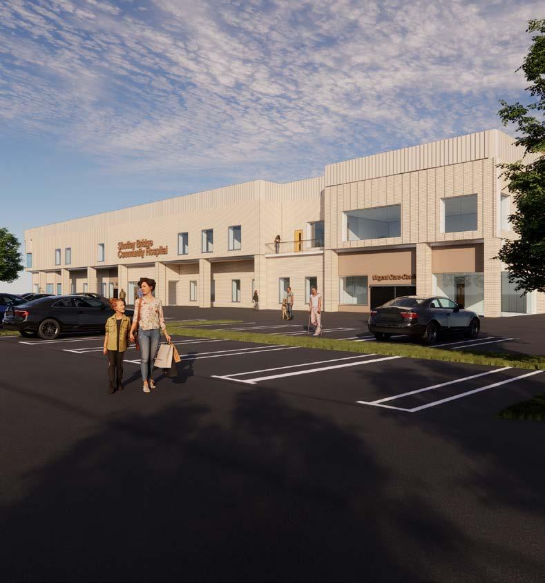
 Fig 2. 3 - Artist’s Impression #1
The two-storey building will sit at a height of 13.2 meters, with each storey having a floor to ceiling height of 2.7 meters. The FLEXI POD® structure will rest on a 340mm foundation slab.
The design provides structural zones and service voids at intervals to accommodate the internal mechanical fixtures, ductwork and steelwork needed at a later stage. The roof also includes a parapet and wooden louvers up to a height of 15.5 meters in order to enforce appropriate safety measures for employees that will require access to this level.

The façade uses a range of materials with a colour palette of primarily brown and cream. The walls are a combination of cream bricks and bronze metal panels with an anodised aluminium finish. The design uses a linear pattern throughout the externals and can be seen on walls that are split into panels.
This continues upwards to the roof level which houses a series of wooden louvres that ties into the linear language of design and minimalistic aesthetic. Glazed fixed and openable windows are used with an aluminium finish in areas that permit it, to aid in patient recovery and provide sufficient natural light for users.
FLEXI POD® is a hybrid solution of traditional build, comprising aspects of MMC for the shell and core, and an off site manufactured fit-out.
Off site products are manufactured at the Merit factories based in Northumberland.
FLEXI POD® can be developed with any client layout and finishes to create any style of building. The internal fit out is undertaken using manufactured PODs and PAMs using the Merit platform design.
Fig 3.1 - FLEXI POD® Concept Drawing

 Fig 3.2- Perspective Section
Fig 3.3 - Elevation A
Fig 3.4 - Elevation B


