11 minute read
Successful Inventions
Caravan chassis and running gear
In this feature on inventions that changed our world we look at the ball coupling, rubber torsion axles, lightweight chassis, and overrun braking systems. Next time we’ll look at four other chassis-related inventions
Caravan chassis and their running gear have advanced beyond recognition since the early days of the 20th century. The result has been a complete transformation in the way we produce and use our touring caravans, especially in Europe. Interestingly, most of these innovations have occurred in the last 40 years or so. Until then, the production of a touring caravan would begin with the construction of a chassis made from steel, probably welded together, and with leaf or coil springs for suspension. Shock absorbers would doubtless be non-existent, as would any means of stability control. Brakes, if fitted, would probably be electro-mechanical and subject to all sorts of issues. First though, we look at a device whose origins date back over 100 years.
The Ball Coupling
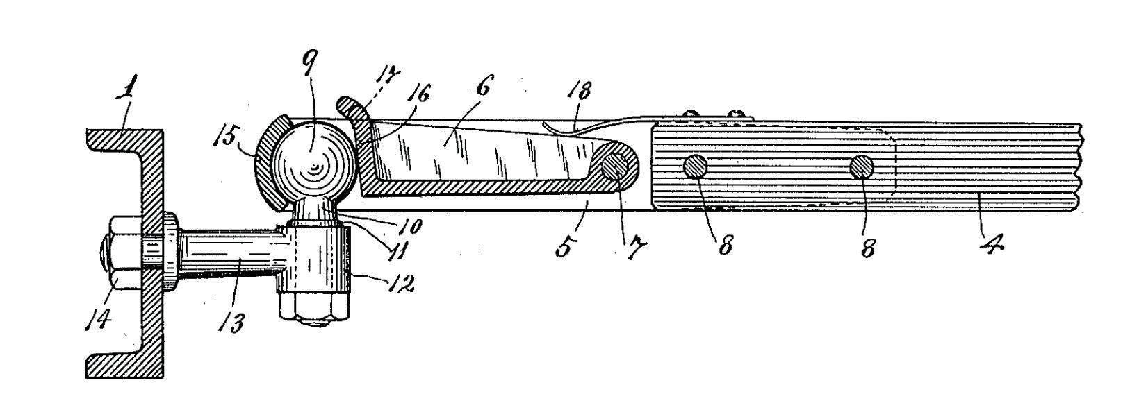
Virtually all caravans and travel trailers in production today use the ball coupling as a means of connecting to the tow vehicle. Such a coupling device first appeared in a US patent (no. 1,147,844) in July 1915. Messrs Milton and Alfred Brice described what they called their ‘pole coupling’ as an ‘extremely simple and highly efficient coupler especially adapted for use to connect the pole of a trailer cart to the rear portion of an automobile.’ As you can see it’s remarkably like the ball couplings we use today. Of course, improvements have been made in the 100 years or so since then. The first was a locking
American patent from 1915
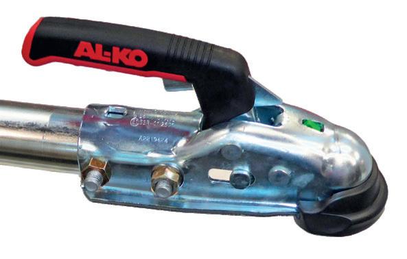
Left: This coupling head from AL-KO incorporates a friction stabiliser. We’ll look at them in more detail
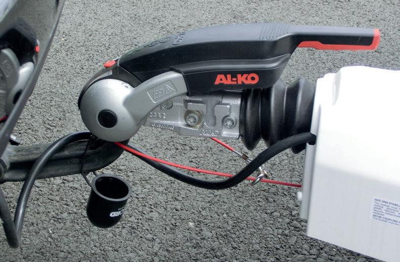
mechanism, introduced by the Brice’s a couple of years later, followed by a variety of sizes to accommodate a wide range of towing needs. In 1934 Franz Knobel, a founding family member of Westfalia Automotive was granted a German patent for a similar device. An update was granted to Westfalia in 1985 by the European patent office (EP0176825A1). It describes a coupling housing as ‘part of a hollow ball… engageable with a ball head attached to a towing vehicle. The ball socket can be locked in its engagement position relative to the hollow ball of the clutch housing.’ It’s fair to say that many patents for similar devices have been filed over the years but the principle of the ball coupling has remained the same. Today, coupling sizes vary by location. In the USA, the standard coupling size is 2” (50.8 mm), whereas in Europe and Australia the ISO standard 50 mm coupling is the norm. However, some countries, such as New Zealand, use 1-7/8” (47.6 mm) as the standard for their domestic trailers. Prior to the ball coupling the most common connection was the straightforward ‘pin and eye’ type still very much in use today. It’s simple and effective but does not provide the solid, play free, connection of a ball coupling.
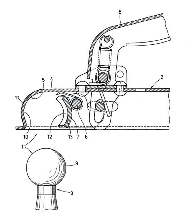
Above: German patent from 1934
Right: B&B hitch head from 1976 Above: modern hitch head from AL-KO

Right: old ‘pin and eye’ type coupling

Rubber Torsion Axles
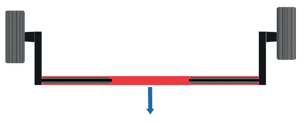
Rubber torsion axles contain rubber chords and a torsion tube within a square or hexagonal axle tube. The outer end of the torsion tube carries a radius arm and stub axle holding the brake drum and wheel. As the wheels move up and down the torsion tube rotates against the action of the rubber chords subjecting them to a shear force. This provides resistance to movement in the way that a spring might. The arrangement means the wheels can move independently from each other, absorbing shocks and giving a better ride than a beam axle would (where opposite wheels are connected by a single beam.) The rubbers also provide a degree of shock absorption, so separate shock absorbers are not always necessary. It’s not clear (to the author at least) when the rubber torsion axle was first invented but the device has revolutionised the world of trailers. One of the first adopters was Airstream who, in 1961, switched from leaf springs to an axle incorporating rubber torsion technology. The axle was known as the Dura Torque, manufactured by a company called Henschen Axle, now part of GKN. In 1967, AL-KO developed its own rubber suspension axle, based on a unique hexagonal axle tube rather than the square tube that had become common. It marked the start
Concentric square tubes and four rubber chords, as used by Dexter Axle, BPW and many others
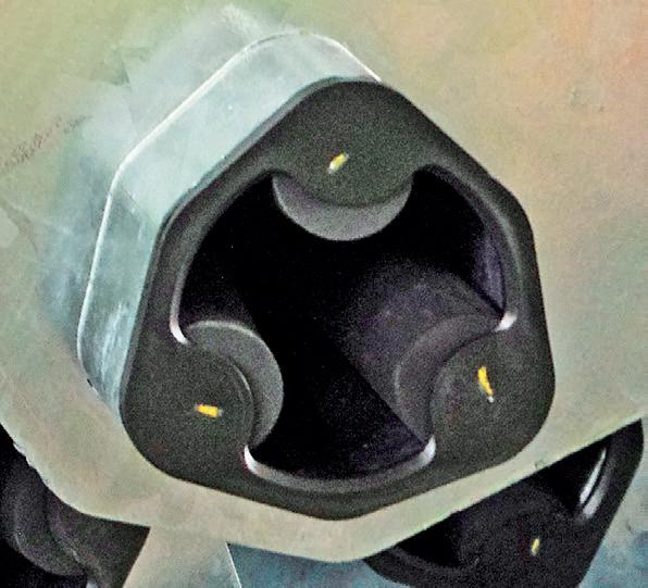
AL-KO’s unique hexagonal tube suspension Rubber torsion axle
Direction of travel
Right: cutaway of a BPW axle tube
Below: an AL-KO axle tube awaiting insertion of the central tube with radius arm and brake drum
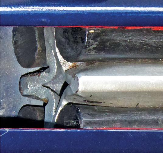
Above: a BPW radius arm with torque tube and brake drum, ready for insertion into the axle tube
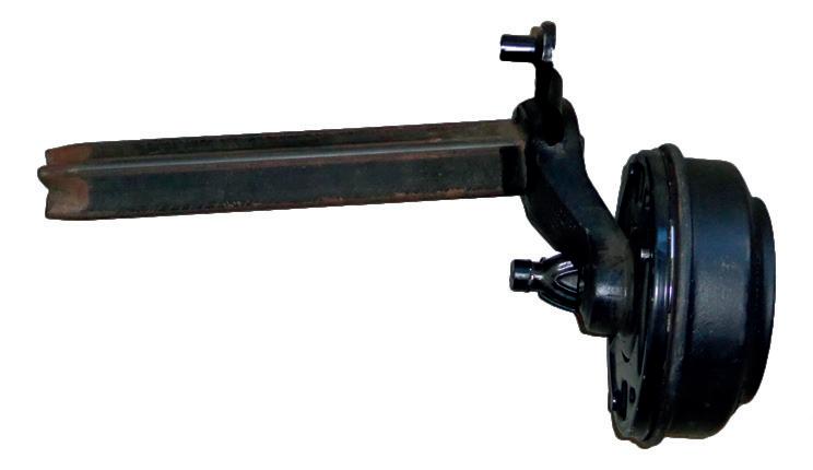
of AL-KO’s axle production with just 520 axles being made in the first year. However, by 1973 the total risen to 100,000 and by 2015, with the help of production facilities across the globe, AL-KO had produced 25 million axles. In 1984 Dexter axle produced its own version, trademarked ‘Torflex’. It used a square axle tube and was the first product branded by them.

Axles in production at AL-KO’s plant in Kötz, Germany
It turned out to be one of the most successful products ever engineered and launched by Dexter. Indeed, Airstream switched to Torflex around the end of 2005. For caravan manufacturers, the advantages of rubber torsion axles over conventional axles and suspensions are considerable - lightweight, inexpensive, maintenance free, in-built shock absorption, quiet in operation, and long lived. It’s normally the rubber that fails by losing its elasticity, but that can take up to 25 years.
Caravan Chassis innovations
In 1957 an advert for a Paladin Commodore caravan in the UK boasted a ‘welded steel chassis that is strongly cross-braced for extra strength.’ The result was undoubtedly strong, but those poor caravan designers were faced with a considerable weight penalty before they even started.
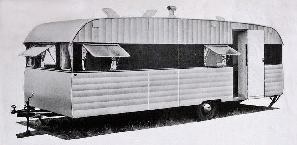
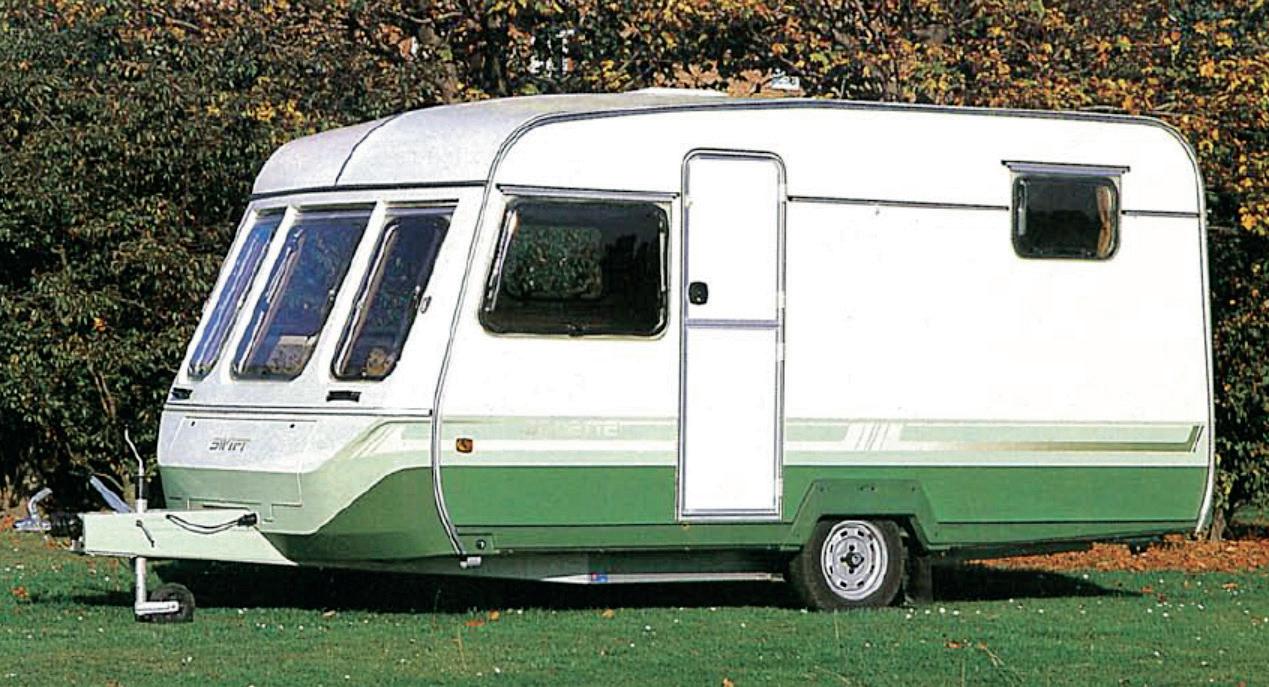
At this time floors would be made of plywood sheets or sometimes even tongue and groove boarding. Naturally, this type of floor needed good support. The first significant step forward came in the 1970’s with the development of bonded floors made of a sandwich construction. These proved stronger and allowed the chassis support rails to be reduced somewhat. By the early 1980’s floors were being bonded using a plywood sandwich with high density foam (Styrofoam) inside. Wooden strengthening battens around the ran around the edge and from side to side. The result was a strong and relatively rigid floor with a typical thickness of 44 mm. This needed much less in terms of chassis support whilst also providing good thermal insulation. The arrangement enabled the chassis to be reduced to two main rails with a drawbar, plus one or two cross members. The chassis and floor effectively became one integral unit with each gaining strength from the other. As the 1980’s progressed, aluminium was often used instead of steel to save weight. However, the problem with aluminium is that it’s not as strong as steel, so you
1957 Paladin Commodore
This B&B chassis dates from the early 1970’s but remained in use until the 1980’s This 1987 Swift came with an aluminium chassis from specialist manufacturer Syspal
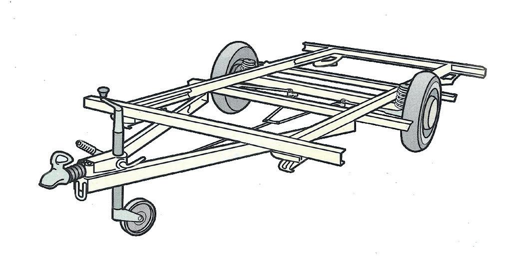
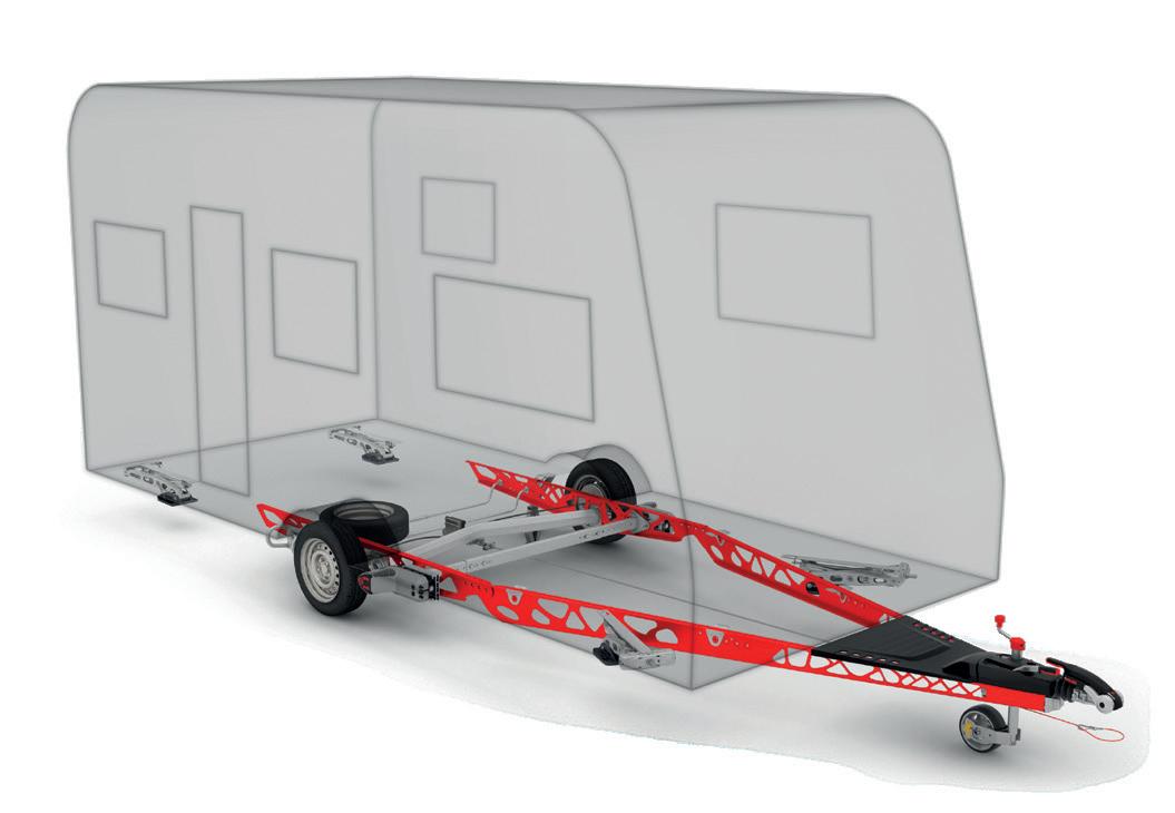
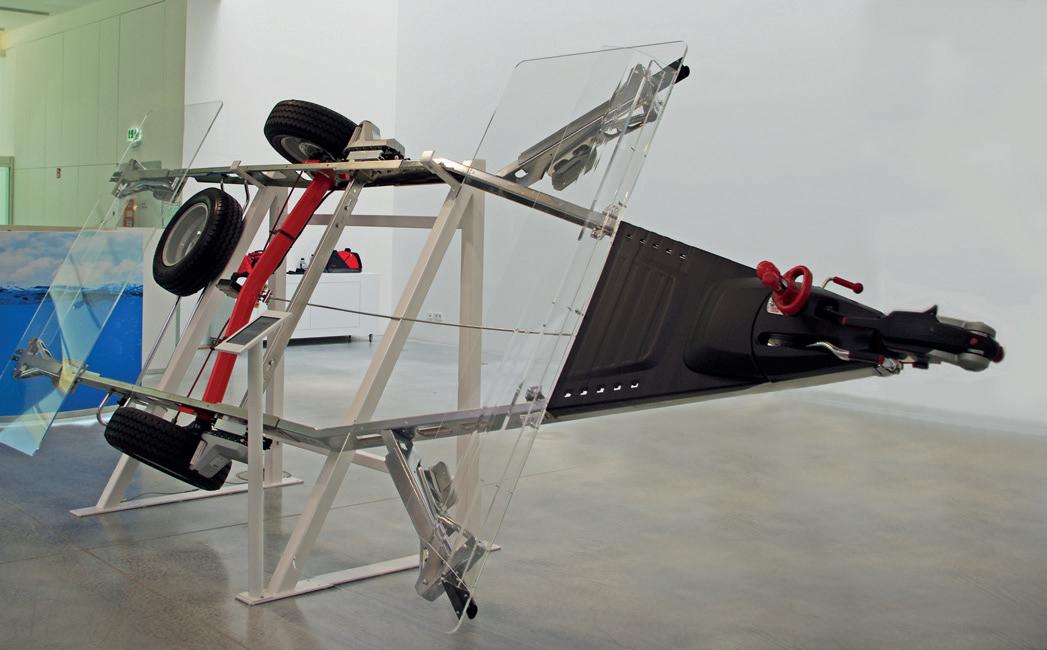
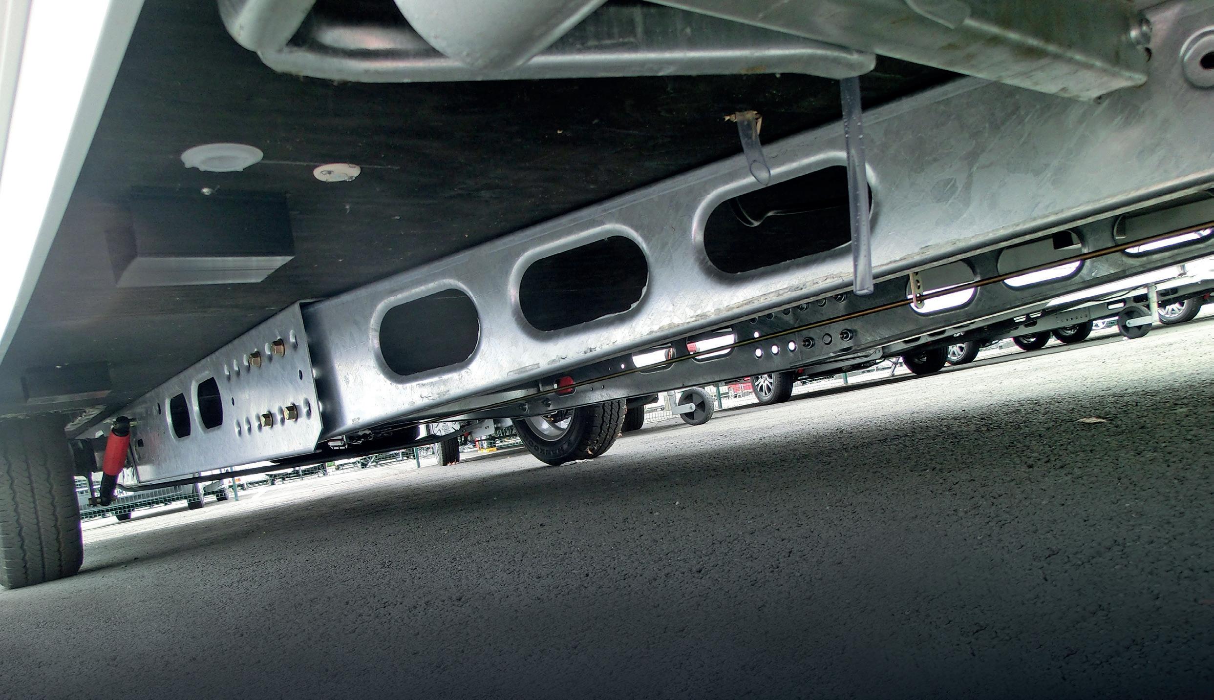
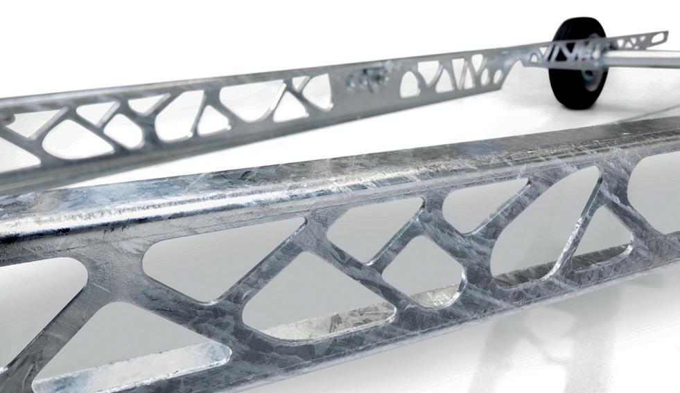
need more of it, offsetting the weight advantage somewhat. Nevertheless, weight savings were achieved and, of course, aluminium is corrosion resistant, so no painting or galvanising is required. This went some way to pay for the extra cost of aluminium which, at the time, was about twice the price. As well as cost, another disadvantage of aluminium is the galvanic corrosion that can occur when steel parts, such as a hitch head and axles are bolted to it. Although these were not major issues, it became clear that aluminium was not the best way forward. This came with the introduction of lightweight galvanised steel chassis rails by AL-KO and BPW in the early 1990’s. Large cutouts saved weight, whilst strength was maintained by turning over the edges of the cut-outs together with the edges of rails themselves. Strong, light and corrosion resistant, this design soon replaced aluminium for the chassis rails.
When bolted together the chassis and floor form a strong foundation to build on AL-KO lightweight chassis with Delta axle and Mammut mover
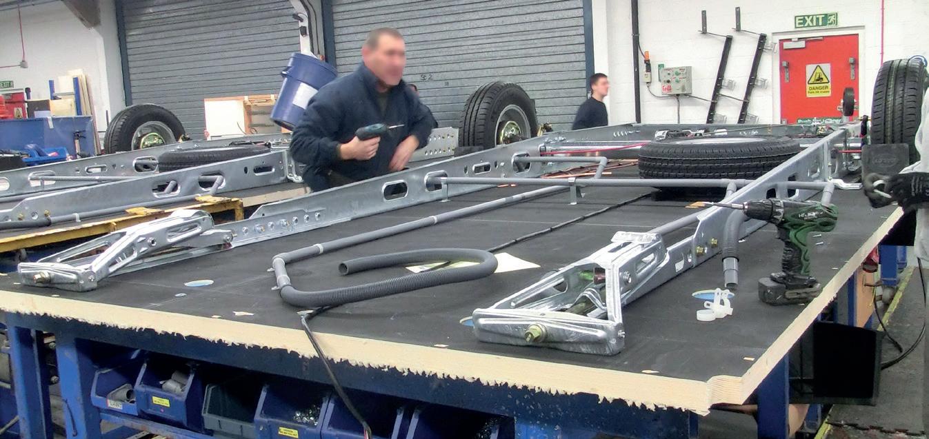
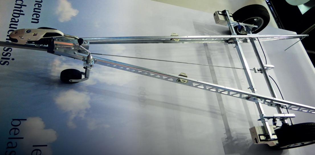
One advantage of steel for chassis rails is that it lends itself to being bolted together. This means the rails can be flat packed and, using a series of holes, the overall length can be varied to suit the length of the caravan. AL-KO calls this its Vario Chassis. When combined with a suitably bonded floor the result is a strong and lightweight platform for the rest of the caravan body and the running gear. This design has been so successful it’s carried over largely unchanged to today. The result is that caravan manufacturers have been able to load their products with ever more goodies to tempt buyers to part with their hard-earned cash. At the Caravan Salon in 2016, BPW showed a new lightweight chassis with extensive triangular cut outs along its two straight rails. Three years later, following AL-KO’s acquisition of BPW Fahrzeugtechnik in 2017, AL-KO launched its own version, the Vario X. It reduces the chassis weight by up to 30% through using a honeycomb construction, said to mimic nature. AL-KO claims the design does not compromise on stiffness. It has already found its way into some production caravans. It’s worth pointing out that, whilst the two-rail arrangement is perfect for the relatively smooth roads found in most of Europe, it’s not ideally suited to areas such as the Australian outback, where much more rugged conditions prevail. In these types of market more traditional designs prevail. Above and below: AL-KO’s super light Vario X chassis
BPW showed this ultra-lightweight chassis at Düsseldorf in 2016
Overrun braking systems
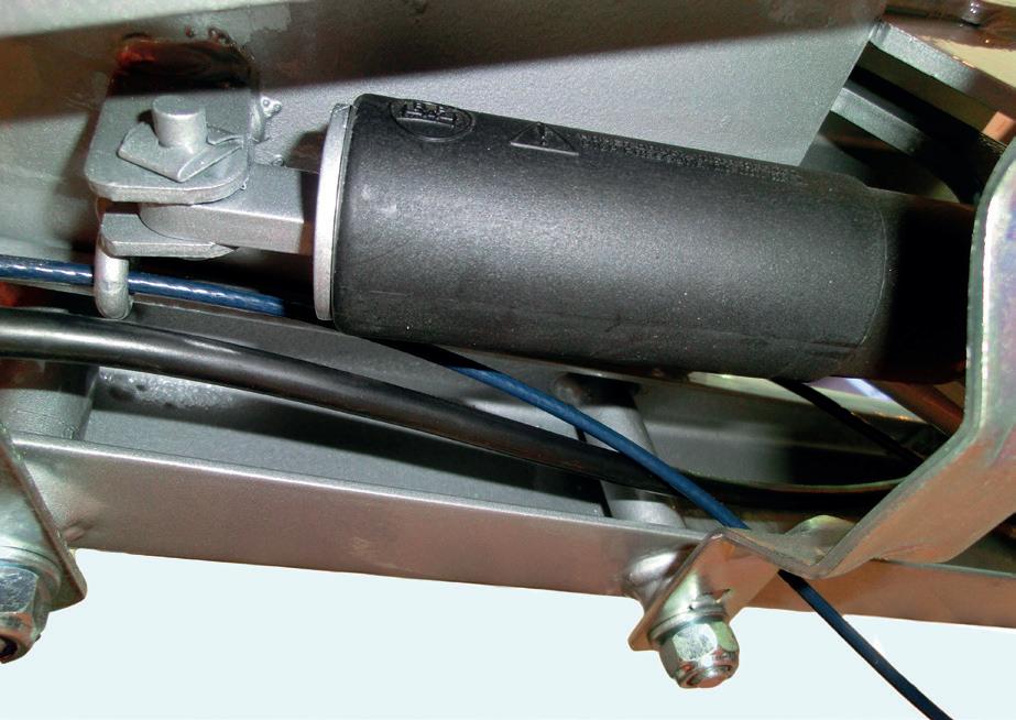
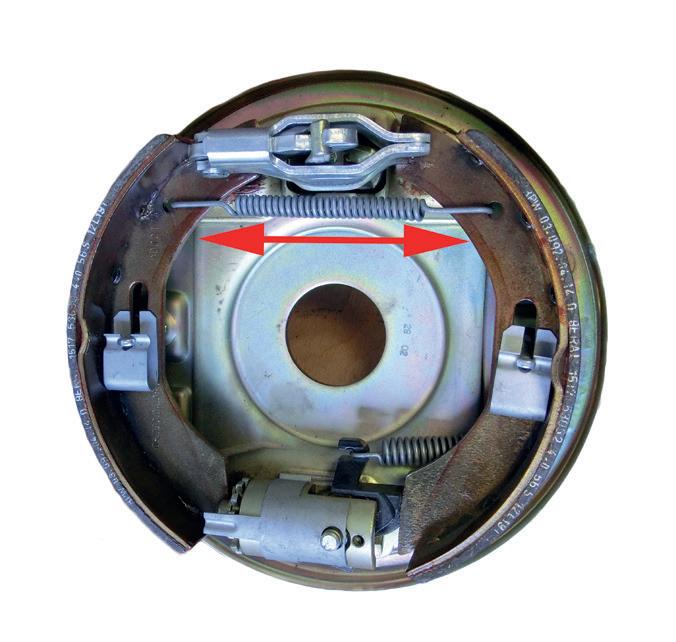
The overrun braking system is another example of an invention whose origins are lost in the mists of time. Basically, it’s a system where, when the towing vehicle brakes, the trailer brakes are automatically applied without the need for any special linkage between the two. It works by using the forward momentum of the trailer to push against the braking tow vehicle. This creates an opposite force which is used to push back a spring damper (1 below). The rearward movement of the damper is then used to apply the trailer’s brakes via a pivoted lever (2) and control rod (3). In this way the trailer’s brakes (4) are automatically applied when the towing vehicle brakes. As the trailer slows the force on the spring damper reduces, thereby reducing the level of braking. What is clear is that the first systems relied on a simple spring without any form of damping. This could have unwanted results. As the trailer brakes were applied the trailer could decelerate to below the speed of the tow vehicle thus quick releasing the brakes, only for the whole cycle to repeat itself. The result was often a severe hammering of the trailer against the tow vehicle and a reduction in braking efficiency. Enter AL-KO founder Alois Kober and his son Herbert. Following a bad car accident in 1952 in which they were both involved, many months of recuperation followed. During that time father and son set about designing an improved overrun brake system, an arrangement that would respond to the slightest pressure rather than ramming the towing vehicle from be- The brake shoes are forced apart by the hind. The first tests were carried out pull on the control rod and cables. This using and old Jeep left over from causes them to contact the brake drum the war. They led to the start of AL- and slow the vehicle down KO’s involvement with the design and manufacture of braking systems. Today all systems employ some form of damping to prevent unwanted hammering. This is usually built in to the drawbar assembly to provide smooth and reliable braking. It often takes the form of a gas filled spring-damp- The gas spring-damper er as shown here. on a BPW hitch
Typical overrun braking system

The author would like to thank AL-KO for their assistance with the preparation of this article.
