29 minute read
Press Releases


By Phil Lambeth, BPGlobal Fuels Technology / Global Alliance
Stage 2 Vapour recovery has been with us in most countries in Europe and the US since the late 1980’s. The European directive setting a cap on total Volatile Organic Compound (VOC) releases was published in 1992 aiming at total VOC reductions by 2010. As the deadline approaches those countries which have not yet done so are looking to Stage 2 vapour recovery to help meet their declared targets. Most of the early adopting countries created their own regulations around approvals and performance but essentially we have the same systems doing the same job in all existing countries. The good news for the UK is that the regulations published recently by DEFRAhere will allow equipment approved to any of the existing European standards to be accepted. There will not be a whole new set of equipment type approvals for manufacturers, users and regulators to work through.
Advertisement
So having been done everywhere else, several times, what more is there to learn for the project in the UK? While the basic principle we all follow is the same there are historic differences in details of how we build, use and regulate our petrol filling stations which affects the end result. This paper shares some of the things BPhas found in 6 years of fitting Stage 2 systems in the UK. It covers the operational reliability of components and looks at some of the technical issues we have faced when we started pumping petrol vapour back to the tanks.
The System
Stage 2 vapour recovery is all about collecting the vapour displaced while cars are being filled on the forecourt. In the UK we currently release about 30,000 tonnes of petrol vapour into the atmosphere each year from this source. Petrol vapour contributes to the formation of ground level ozone, a green house gas which can result in health problems for humans and is hazardous to plant life. While vapour lost like this is only about 2% of the total volatile organic releases it is growing in proportion as other areas are controlled and importantly is one we can do something about.
History
BP’s implementation in the UK started when the original European VOC Directive was published back in 1992. Like many others we started at that time to fit the underground pipework required to transfer the vapour from the pump back to the tank. A number of options for this have been considered and tried. The vapour flow rates and output pressure of the pumps mean that you don’t actually need a big pipe to get the vapour back to the tank. Having looked at smaller bore pipe systems we have however come back to standard 1.5” or 2” pipes underground, connected into a single return to a tank because these are standard sizes used on the forecourt, easily handled and big enough to avoid being damaged.
We have tried pipe in pipe systems –pulling a 15mm flex pipe back down an existing suction line to avoid any need for digging up forecourts when retrofitting. These have had some success in Germany but the key difference is that the German experience was based on welded pipe systems. In the UK we have screwed joints. At every connection and bend where the pipe is screwed into the fitting there are internal sharp edges. In our tests we could not get the draw wire past these edges let alone get a pipe through. So that was abandoned.
In late 1999 after publication of proposals for Stage 2 in the UK by the Dept of the Environment we looked at the numbers and given that fitting as new was less than a quarter of the cost of retrofitting decided there was a clear business case to implement stage 2 on all new sites in the UK from them on.
To date we have 163 sites in the company network operating with Stage 2 vapour recovery.
Reliability
Maintenance for Stage 2 has not been a priority. If a problem was found during other works to the dispensers then it would be fixed but we have had no specific regime of call outs or checks to make sure they are working. That noted BP’s maintenance providers advise that the vast majority are all working and when we have had occasion to check we have found that they are operating more or less as originally set up. We are comfortable that the stage 2 systems we have installed are operating reliably.
The selected systems were chosen for reliability based on our operating experience elsewhere in Europe. Dispensers were supplied by Tokheim and in the last 4 years principally by Wayne.
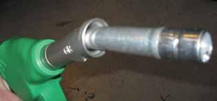
All use the Elaflex vapour recovery nozzle, Stage 2 hoses with integral swivels and break couplings and these have all proved reliable in operation. Nozzle issues – spout damage or wear at the venturri tube - are the same as for standard nozzles. There are no additional issues affecting these Stage 2 components in the equipment.
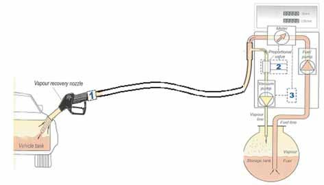
PVR II will collect the vapour displaced from car fuel tanks as they are filled on the forecourt
Pumps need to be fitted with
•a new nozzle, coaxial hose and splitter adaptor •a vapour pump •a way to match the vapour recovery flow rate to the delivery flow rate which can be:
1. a mechanical proportional valve in a special nozzle 2. an electronically controlled proportional valve in the pump 3. an electronic speed control for the vacuum pump motor
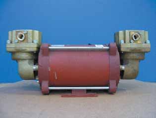
The vapour recovery pumps we have used are piston pumps from Rietschle Thomas (formerly ASF Thomas) and Durr. Most units are direct driven with a single motor driving the two pumps but we did have belt driven pumps in some of the earlier units. Direct drive removes the risk of reduced operating speeds or failure caused by belts slackening and slipping.
The vapour flow rate is controlled by Burkert or Asco proportional valves driven by a control system which uses the meter pulse to keep the vapour return flow matched with the fuel delivery rate. The control systems for these valves allow us to simulate the meter pulse rate and thus check on vapour flow rates without the need to be dispensing fuel – the so called “dry test” of the system. These valves are the core of the system and are used in many other critical operations in a range of industries with a high level of reliability. We have not had any issues with these valves to date.
The remaining main component worth noting is the 1” double poppet shear valve we fit at the dispenser base on the connection to the return to the tank.
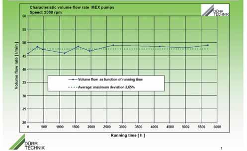
As an example of the reliability of one these key components, tests of vapour flow rate vs time in a long term running test of the Durr vapour pumps have shown that over 5,500 hours of operation they have stayed within 2.6% of the set level. 5,500 hours of operation is equivalent to having pumped 20 million litres of fuel vapour, ten years of operation on a busy fuelling position.
Our experience gives us confidence in the reliability of these field proven components but ultimately it is a question of how it all works together. Reliability is a function of the sum of parts and how they are put together. In Germany and the US it has been found that a significant proportion of systems have failed to maintain their reliability and deliver the required VOC reductions. In any comparison however it must be remembered that these markets were early adopters with a significant proportion of early development equipment. Most installations were also field fitted. With the benefit of this experience, the selection of proven components and, when it comes to retrofitting, rigorous quality assurance the UK should be able to achieve a very high level of compliance without the need for excessive compliance testing.
The Site
Experience has however shown that there are some particular effects of running Stage 2 which have caused us problems which are in need of some innovative solutions.
The first thing to note is that Stage 2 is noticeable on the forecourt. The
Pumping vapour back to the tank instead of the tank drawing air in through the vent as fuel is sold means that the vapour in the tank space is much richer, close to saturated. As a result we see increased condensation in the vent and vapour return pipework. Pressure changes at fittings and bends as well as cooling on cold steel above ground in the winter causes fuel to condense out of the vapour flow. As a result of this higher level of condensation we see increased cases of liquid blow back into connection hoses, or small liquid releases at the vapour poppet connection when the tanker is being connected or disconnected and in extreme cases blocked Stage 1a vapour return lines. Each of these problems can present a hazard to the delivery driver or the site and can result in aborted deliveries. The frustrating element is that when we come along to clear out the condensate we find that it has gone. The condensed liquid over a short period of time simply boils off again into the vapour space in the pipes and tanks.
To avoid problems, associated with saturated vapours, we must make sure we have the right equipment for the vent and vapour lines. Proper fuel grade rated pipe systems connected with low loss bends and fittings to avoid sudden pressure drops. There will be liquid in these lines so falls back to the tank are essential and traps to avoid any blockage on drop lines need to be provided.
Insulated materials on above ground vent manifolds might help and the poppet valve location and design needs to be reviewed to make sure there are no spots where condensate might sit and be blown out when the valve is opened.
Stage 2 also affects tank pressures. Conventionally tank contents are drawn down as fuel is removed from the tank. Provided you have a fairly steady sales pattern the pressure in the tank remains just below atmospheric pressure. With Stage 2 however we have found, particularly in cold weather, that tank pressure can rise quite rapidly. The fastest we have seen was in the region of 10mbar/ hour.
Pressure in the tank is controlled by the pressure vacuum valve on the vents. These were designed to help control the vapour flow back to the tanker for Stage 1 and provide a safety relief if things got blocked. On the
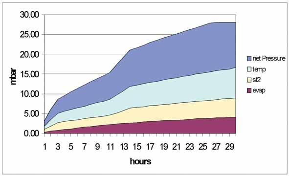
Pressure increases in the tanks are caused by three main factors.
•Petrol, left on its own in a closed space, at around 15C, will simply evaporate and build a natural vapour pressure of between 50 and 100 mbar when the vapour above the liquid becomes saturated. In a ventilated space, like our tanks, it will keep evaporating trying to attain that pressure until it has all boiled off. The rate at which it boils of is determined by the air / vapour layer immediately over the fuel. If there is air immediately over the fuel then the rate of evaporation, the rate of pressure rise will be faster.
•Stage 2 returns vapour back to a single tank, which is then balanced between all the tanks through the manifolded vent system. Stage 2 systems are normally set up to return between 95% and 105% of the volume of fuel being taken out of the tank. If the set up is just over 100% you will be adding volume and thus increasing the tank pressure. This effect can also be seen if the tank receiving the vapour is particularly small.
•Temperature however plays the key roll. Tanks remain at a fairly steady temperature around 12 degrees. When you are pulling back air and vapour at an outside temperature which can be significantly lower than this it expands in the tank causing further increase in pressure. Temperature seems to be the most significant effect and certainly all the associated incidents we have seen have been over winter periods when this temperature differential is at it greatest.
So Stage 2 does increase the pressure in the tanks and the rate of increase is greater in the winter months.
The consequences of operating the tank at an increasing pressure is nuisance caused by vapour spluttering from vents, concern about rattling pv valves and most seriously, vapours escaping into tank chambers. Modern tank chambers do a very good job of containing escaped vapour. We have found vapour leaks on tank gauge caps, threaded fittings, tank lid bolts and, on one site, a small crack in the submersible pump riser. These tiny leaks were all solvable but very difficult to track down and most were not detectable by normal precision testing methods.
As Stage2 is deployed across the full UK network there is potential for major problems. We need to make sure we avoid problems of hazardous atmospheres in chambers or an increase in ground contamination which would result from vapour leaking out of chambers. Coping with the natural vapour pressure and hazardous nature of the fuel means that we must ensure a high level of engineering standards on the assembly of tank lid components. Suitable testing needs to be carried out following any works on the tank lid.
In Germany and the Netherlands however we don’t have this problem of pressure in tanks. Tanks are maintained at atmospheric pressure with orifice plates. A10mm hole in the vent, which allow air in as the fuel is drawn down, relieves excess pressure as it slowly rises but still acts as a brake on large release during the tanker unloading. Asafety release is still required to allow venting in case a blockage in the vapour return to the tanker occurs. Orifice plates are able to control the losses from vents during unloading within the limits currently allowed under the stage 1 regulations. Having shared these issues with the Environment Agency and DEFRAthey have agreed to remove the previous prohibition and allow the use of orifice plates for Stage1 vapour recovery systems in the UK.
Orifice plates are, however, not an ideal solution as clearly a routine breathing loss is introduced, releasing some of the vapour we are recovering with the stage 2 system. Our main aim should be to eliminate the core problem of pressure in the tank and eliminate losses to atmosphere. Tank pressure management systems will remove and condense vapour from the tank ullage, reducing the pressure with the aim of ensuring the tank stays at or just under atmospheric pressure. Such systems will be required by new air and water quality laws in California and are required now in Luxembourg. It is early days for these systems and we have no real extended operating experience of the solutions currently available. We will see further development in the near future but for the time being there remains more work to be done.
Summary
Stage 2 vapour recovery in the UK is the same standard process we have used across most of Europe over the last 15 years. From BP’s 6 years of experience with installations in the UK it is clear that changes to some of the accepted standards are required to ensure that we apply it here safely and reliably. We know that with the right equipment and engineering standards the overall aims to have a sustained and reliable reduction in VOC emissions can be achieved.
By Jane Mardell, APEABusiness Manager
I am writing this article this year to make sure you understand the procedures for inclusion in the 2008 Yearbook.
In order to ensure that your details are included in the Yearbook it is essential that you complete the registration form and return it to the APEAoffice. I register all forms received on the membership database against the members’name.
As shown on the form enclosed with this issue of the Bulletin, your Registration Form must be returned to the APEAoffice for your details to be included by 1st April. This ensures that the information in the Yearbook is correct.
Even if you do not wish to advertise in the Yearbook, to be included in the Classified and Directory pages you should complete the form as follows:
1.Check your contact details are correct on the form and that these are the contact details that you wish to be included into the Yearbook. If you wish to change them please amend the form. As an APEAmember you receive one free ‘Classified’entry.
2.Complete the Directory table
This contains a list of the Directories that will be included in the Yearbook.
Please tick the box next to the Directory listing that is relevant for your business. You receive one free box. Additional boxes are charged @ £26.00 plus VAT.
3.If you have ticked additional ‘Directory’boxes, complete the payment box at the bottom of the form.
4.Fax or post the form to the APEA office by 1st April 2007. This enables the production of the Yearbook in time for Autumn delivery.
I will then record the details from Registration forms received.
If you have any queries or need another form or a advertising booking form please do not hesitate to contact me at the APEAoffice on 0845 603 5507 or by email at admin@apea.org.uk
Additional forms can be downloaded from the APEAwebsite on the Publications page at www.apea.org.uk
AHistory of Petrol Filling Stations - Part One The Coming of “Rock Oil”
By Brian Baker
“Then there was the matter of the $526.08”
To pinpoint exactly when the petroleum downstream industry started is like asking “When did man first start to walk?” Simply we do not know but there are several incidents that occurred within a few years of each other to give us some insight as to when it all started.
Oil, it is said, has been with us for at least 3,000 years when reports of a black ‘tar-like’substance oozed its way through the rocky areas of the Egyptian city known as Hit (where the ancient civilisation known as the “Hittites” resided on the banks of the River Nile) They and indeed the other ancient civilisations of both the Chinese and Greek have a black oily substance recorded in the annals of their respective histories and applied the substance to the skin as it seemed at the time that it had healing properties and helped deal with such ailments as back pain, headaches, diarrhoea, stomach upsets and skin disorders. In fact it was the Greeks that first recognised that the use of Oil could be used in warfare to bring down their enemies in battle by either tipping it hot or on fire or catapulting it over considerable distances.
Indeed the word petroleum never existed until the middle of the 1850’s when scientists coined the phrase from the words “Petra” which is Greek for “Rock” and “Oleum” that is Latin word for ‘Oil’. It was applied in the same sense as a codeword, much like we use acronyms or letters to identify a particular item.
You will have noticed the saying at the head of this article “Then there was the matter of the $578” This comes from the opening words of book known as “The Prize – The Epic Quest for Oil, Money and Power” written by Daniel Yergin in 1991, that tells the story of the Oil Companies that dominated the world as well as a short history on the coming of petroleum and its powerful use as a political and aggressive tool for bargaining on the world stage.
New APEAtel/fax 0845 603 5507
The sum mentioned is referring to an unsettled bill for a report conducted by a Professor Benjamin Silliman Jr, a chemist from Yale University who undertook private appointments in between earning his modest salary at the University
Silliman (1779-1864) actually developed a technique to fractionate
petroleum. which is a method of distillation. Silliman’s report, though brief was summarised to say that the sample of “Rock Oil” he had been handed was indeed valuable and could rival the lighting fuels in common use at the time which was Whale Oil.
The Whale Oil used extensively at that time smoked considerably and offered a poor light. The first petroleum oils used before fractionalisation/distillation was invented offered a brighter light but were found to be more dangerous and caused many fires. It was only after the Scientists learned to separate the different “fractions” to use the higher flash point oils that petroleum (or Kerosene as it became known) as a fuel for lamps became successful. The same technique was used a generation later after the combustion engine was invented when the lower flash products were needed.
The sample that Silliman was supplied with came from an area in North West Pennsylvania in the close proximity of a small town known as Titusville. The Town itself was very close to a locally named area referred to as “Oil Creek” that which was known for the black sticky and odorous liquid that seeped through the rocks and locals applied rags to soak it up and squeeze into small wooden barrels.
We do however have to refer to the mastermind behind the commissioning of Sillman’s report, George Bissell, an Industrialist (1821-1884) who had originally observed the primitive oil gathering industry in Titusville. After Silliman’s report in 1855, he founded the Pennsylvania Rock Oil Company in 1856 with a colleague, James Townsend, a Merchant Banker and began selling oil as a fuel for lamps.
After seeing pictures of a derrick drilling for salt, Bissell conceived the idea of drilling for oil, rather than mining it. At the time such an idea was thought ludicrous but the technique was used
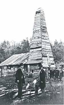
eventually and on Saturday 27 August 1859 on a far at Titusville, Pennsylvania, oil was struck at a depth of 69 feet (about 21 metres) Bissell invested heavily from this day on and went onto become known as the father of the Oil Industry.
Curiously, the whole sequence of events was observed by the local tribe of Indians, known as the “Seneca” which is why Rock Oil was also known as “Seneca Oil” and their Chief’s name? ….Chief Red Jacket!
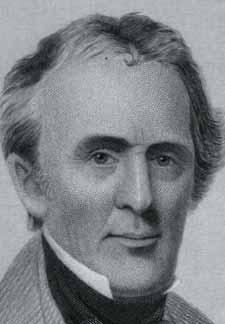
Returning now to a defining moment in our history is man called “Colonel” Edwin Drake (1819-1880), who used the military title to impress the backwoodsmen of the area as he was never in the army but by appearance had a strange bearing and likeness to Abraham Lincoln, the US President of the day. Drake was a Railroad Conductor, suffered poor health and was unemployed at the time. He bordered on being an eccentric and drank heavily and was appointed by George Bissell to commence the drilling process in the search for Rock Oil in 1856. Drake recruited a local Blacksmith, “Uncle” Billy Smith to assist him and they commenced the slow process in 1858. Smith also employed his 15 year-old son, Samuel and his daughter, Margaret Jane to assist. Their pay was just $2.50 per day for all three of them.
After a year there were no signs of oil and funds were running too low to continue drilling. The other director of the Pennsylvanian Rock Oil Company, James Townsend had written to Drake a few days earlier asking him to stop the exploration but by the Saturday (27th August 1859) the letter had not arrived and overnight a gusher from Drake’s well was met in the morning of the following day with great jubilation and relief.
Word quickly spread and within 3 years there were literally hundreds of wells all across Pennsylvania and Ohio that started the “Black Gold Rush”. A rival for whale oil had been found and within a couple of years, markets were being opened up beyond the USA.
So our story begins. We had the fuel before its actual longer and established use became known and it was not until the discovery of gas, then electricity that its use as a major means of lighting ceased. The invention of the combustion engine introduced a new use for petroleum and from 1880 to the beginning of World War 1 would see a phenomenal rise in the use and demand for oil, a matter that will; be progressed in the next edition of the Bulletin.
Drake’s Oil Well Colonel Edwin Drake
By Dr. rer. nat. Wolfgang Schrittenlacher
Surface Water found at Petrol Stations can be contaminated by light oils and fuel, therefore this water cannot be discharged directly to a public foul sewer. It is prescribed that these water/oil-mixtures are collected and the silt and oil parts are separated from the mixture before the cleaned part can flow to the public foul sewer. The forecourt separators must be 'full retention separators' that means bypass systems are not allowed /1/.
The layout of a forecourt separator is dependent upon the size of the site, the maximum volume of the road tanker compartments and the amount of silt that is to be expected /1,2,3,4/. If high amounts of silt are likely a two-stage system is favourable. In the first stage mainly the silt is separated and in the second stage the light oils. The operating condition for separators can be very different depending on the site condition, the rain fall and the state of spillage. Though it is unpredictable whether the separator is in normal operation or not. It is therefore prescribed an automatic warning system with optical and audible alarm controlling whether the oil reserve volume comes to its limit. Most separators are equipped with an automatic closure device. Astandard layout of a separator is shown in the following figure.
The feed pipe and the discharge pipe are on the same level. So the separator is filled to this level with liquid. The inflowing mixture can come to a relative rest and the heavier parts are sinking to the bottom as sludge and the lighter oil parts rise to the surface. The separation grade is dependent on the flow speed and on the differences in density and on the size of the oil droplet.
To improve the separation efficiency there is a widespread use of coalescence filters (not shown in figure 1). The buoyancy of small oil droplet is very small so especially the smaller ones remain freely suspended in the liquid and though flowing into the discharge. The coalescence filter is basically a metallic grid array having several layers. If water containing oil droplets flows through the grid a portion of the droplets become stuck to the grid. At the surface of the grid they unify with other droplets out of the liquid until the buoyancy force is sufficient and the bigger droplets ascend to the light oil layer.
Because the inlet of the discharge pipe is below the surface level, there is only water flowing into the discharge pipe. If the amount of light oil increases, the separation layer between light oil and water content lowers. Above the inlet of the discharge tube is a float with a density of about 0,9 g/cm3. The float is sinking down in light oils and so closes the discharge pipe if the maximum oil capacity is reached. In such event there is no flow out and the inflowing mixture leads to an increase of the liquid level in the separator. At a certain level the oil containing mixture would flow into the surface rainwater
sewage.
To prevent such accidents a two-step alarm system is commonly in use as is exhibited in figure 1. The separation layer sensor is immersed in the liquid. If the separation layer comes close to 80 % of the light oil capacity an alarm is generated. The Oil-Layer should therefore be removed by the Contractor as soon as possible. If this was overstayed the liquid level will increase according to the inflow. If the tolerance level is reached there will be a second
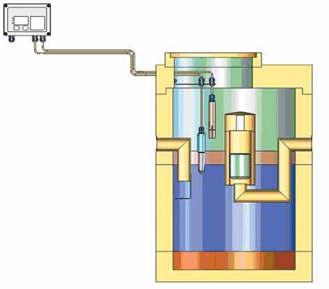
Figure 1: Scheme of light oil separator
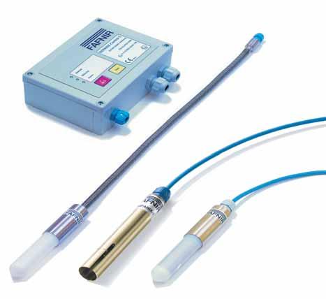
Figure 2: Separator alarm system; in the middle an overspill alarm sensor is shown; the other two sensors are different versions of separation layer sensors; there is one electronic evaluation unit for both type of sensors yielding audible and optical alarms.
alarm. The latter must be served instantaneously otherwise an overspill could happen.
Thus the structure of the alarm system as shown in figure 1 gives a sufficient level of security and fulfils the current regulations. An example of a set of such sensors with evaluation electronic is shown in the next figure 2. The evaluation electronic has to be installed outside of the hazardous zone f. e. in the station building. It evaluates the signal from the separation layer sensor and of the overspill alarm sensor.
The sensors have to work properly under adverse conditions. Additional to light oil and sludge the mixture can contain grease and leaves especially in autumn. So they should be a rugged construction to withstand these environmental conditions.
Even without any alarm maintenance of the separator should be done at least twice a year or 6 monthly. The level of sludge must be detected and the sludge should be removed if the amount is more than half of the allowed capacity. An automatic sensing system for the sludge would be desirable but such systems are not available at acceptable costs. So the sludge level must be tested by hand in appropriate intervals but at least twice a year. Because spillage of gasoline fuel can cause an explosive atmosphere the separator alarm system must be ATEX approved. The conditions can vary widely as was investigated in a detailed study /5/ but explosive concentrations can occur with certainty. Aproblem arises for light oil separators by the increasing use of biofuels and their blends. For bio-diesel (RME) the density is closer to the density of water and the separation efficiency is reduced. This was investigated in some detail in a DGMK study /6/. Here also the temperature influence and the role of defrosting salt was tested. Other and also difficult problems arise for the ethanol blended fuels. Because ethanol is soluble in water the ethanol in the inflowing mixture diffuses out in the water and will flow uncontrolled into the discharge. Therefore the limiting values for the total organic carbon content (TOC value) in the discharge water of 5 mg/l for class I separator and 100 mg/l for class II separator may be difficult or impossible to achieve. This problem is still unsolved.
Bibliography
/1/ Pollution Prevention Guidelines
PPG3; Use and design of oil separators in surface waters drainage systems; Environment Agency (April 2006) see www.environmentagency.gov.uk
/2/ BS EN 858-1:2002; Separator systems for light liquids; Principle of product design, performance and testing, marking and quality control.
/3/ BS EN 858-2:2003; Separator systems for light liquids; Selection of nominal size, installation, operation and maintenance.
/4/ Design, construction, modification, maintenance and decommissioning of filling stations (2005) ISBN 085293419X; Association for
Petroleum and Explosives
Administration.
/5/ DGMK Research Report 617; Untersuchung zur Zoneneinteilung in Leichtflüssigkeitsabscheidern (2006); Investigation of hazardous zones in light oil separators. (www.dgmk.de)
/6/ DGMK Research Report 643;
Leichtflüssigkeitsabscheider und
Biokraftstoffe (2005); Light Oil
Separators and Biofuels.
It is with great sadness that I have to report on the sudden death of the Associations Hon Secretary Paul Craven.
Paul had been diagnosed as having cancer on November 30th and passed away in hospital on Tuesday December 19th after a very short illness.
He is pictured here enjoying the APEAevent, conference and dinner and was in Malta on 25 November taking an APEAtraining course.
Many members of the Association who have benefited from a training course will remember Paul, his easy manner and dry wit that helped students through the rigours of both legal and technical training.
In 1965 Paul Craven joined East Suffolk County Council, Weights & Measures Dept as a trainee. In 1974 following Local Government reorganisation worked for Suffolk CC under his then Chief Ian Halliday and as a Weights & Measures Inspector, had his first taste of Petroleum work. Paul joined the APEAand his involvement in the Eastern Branch first as committee member, later as Chairman took this multi skilled trading standards officer closer to Petroleum. His contribution was recognised by colleagues when he was elected chairman of SELCOG, and a short tribute by the present chairman Steve Rowe follows. Paul also made a valuable contribution to the Blue Book and led the section on dispensers.
Paul retired from Suffolk CC in March 2006 and his interests were many and varied but he was always a mechanic at heart. In 1965 he started riding scramble bikes most weekends and reached a sufficient standard to be sponsored by AJS for a couple of seasons. However he never lost his interest in bikes and was still riding his own Miaco 490 Moto-cross on occasion and his Honda Fireblade up until the last. He had just started sharing his interest with his young grandson Ben, who at just over 2 years old has became the proud owner of a mini bike from Grand Pa, and in later years had enjoyed rallying vintage sports car with a friend.
He always claimed his move onto the APEACouncil was generated in the “Sole Bay” one of his favourite Pubs in Southwold when he was persuaded to put in for election as The Hon Secretary. He made an application and was duly elected; his touch has been light and friendly during his period of office, and he made many friends.
As a remark of his respect in the Association 9 members of council attended his funeral on 3rd January at Kessingland in Suffolk along with his many friends from all walks of life.
On a personal note I have lost a friend and valued colleague who it was a pleasure to work with. Our sympathies go to Paul’s wife Greta, his three daughters Clare, Lisa and Kim, his Grandson Ben and Paul’s parents.
Jamie Thompson
It was my great pleasure to know Paul personally and professionally over a 13-year period. As a long-term member of the South East Licensing Co-ordinating Group (SELCOG), Paul always gave unstinting support to both the group and me personally as Chairman.
Paul was always perceptive and his many contributions to the group helped develop policy at both regional and National levels.
Paul was a fantastic communicator and it was a pleasure to observe Paul talking and exchanging views with other Local Authority representatives from around the country.
Paul was universally popular with everyone he met and it was his honesty, his passion and his marvellous humour that always made it a joy to work and talk to Paul.
As the Chairman of the group I would like to say on behalf of the 32 members a huge thank you to Paul, not only for his professional contribution but for just being his engaging self and promoting those characteristics of pragmatism and humour so missing in today’s sterile working environment.