11 minute read
Leave no stone unturned to analyze problems and P

from Auto Service Professional - May/June 2013
by EndeavorBusinessMedia-VehicleRepairGroup

Real-world voltage drop testing
Leave no stone unturned to analyze problems and discover solutions
By Alex Portillo
Alex Portillo is the head technician of Car Clinic, a state-of-the-art automotive repair facility in Mahopac, New York. He is a protégé of Jerry Truglia and has been trained by Automotive Technician Training Service and is TST certif ed. Alex’s real-world, indepth diagnostic articles will appear in Auto Service Professional on a regular basis.
Not every electrical problem you run into is the result of an open in a wire or in a component. It might be rare, but electrical resistance at a connection or internal to a wire can cause very real driveability problems.
So, before we get into a case study that illustrates advanced voltage drop diagnostic techniques, we are going to cover what voltage drop testing even is for those who are not acquainted with using their meter or Power Probe for this task.
How to perform a voltage drop test
Essentially, a voltage-drop test measures how much resistance electricity runs into as it passes through a load. A reading of up to 200 mV is permissible, but in the real world it is rare you will see voltage drops more than a few dozen mV.
But, as a nice rule of thumb, 200 mV is the highest permissible voltage drop on all vehicle components aside from a computer component, where 100 mV or less is permissible.
Let’s work with an overly simplif ed headlamp circuit, pretending that after replacing the bulb the light is still dim (see Figure 1 on page 28). If it helps, follow along in our
Voltage drop tests
Bad reading: More than 200mV
example with a black pen and a red pen, pretending they are your meter’s black and red test leads.
Always check system voltage f rst, using V DC on your meter.
• Check that the battery has 12.6 V. • If voltage is low, the battery needs to be charged. • Isolate where the problem is in the circuit by doing a quick voltage drop test. • In order to f nd out if we have a good voltage drop on the feed side, all we do is put our red lead on the positive terminal of the battery and our black lead on the feed (positive) side of the lamp. Positive to positive. • In order to f nd out if we have a voltage drop on the ground (negative) side, we put our black lead on the negative battery terminal and our red lead on the ground side of the lamp. Negative to negative.
Positive to positive, negative to negative: that’s a voltage drop test!
Let’s try to visualize this. If the feed side of the lamp is good and the ground side
Circle 110 on Reader Service Card
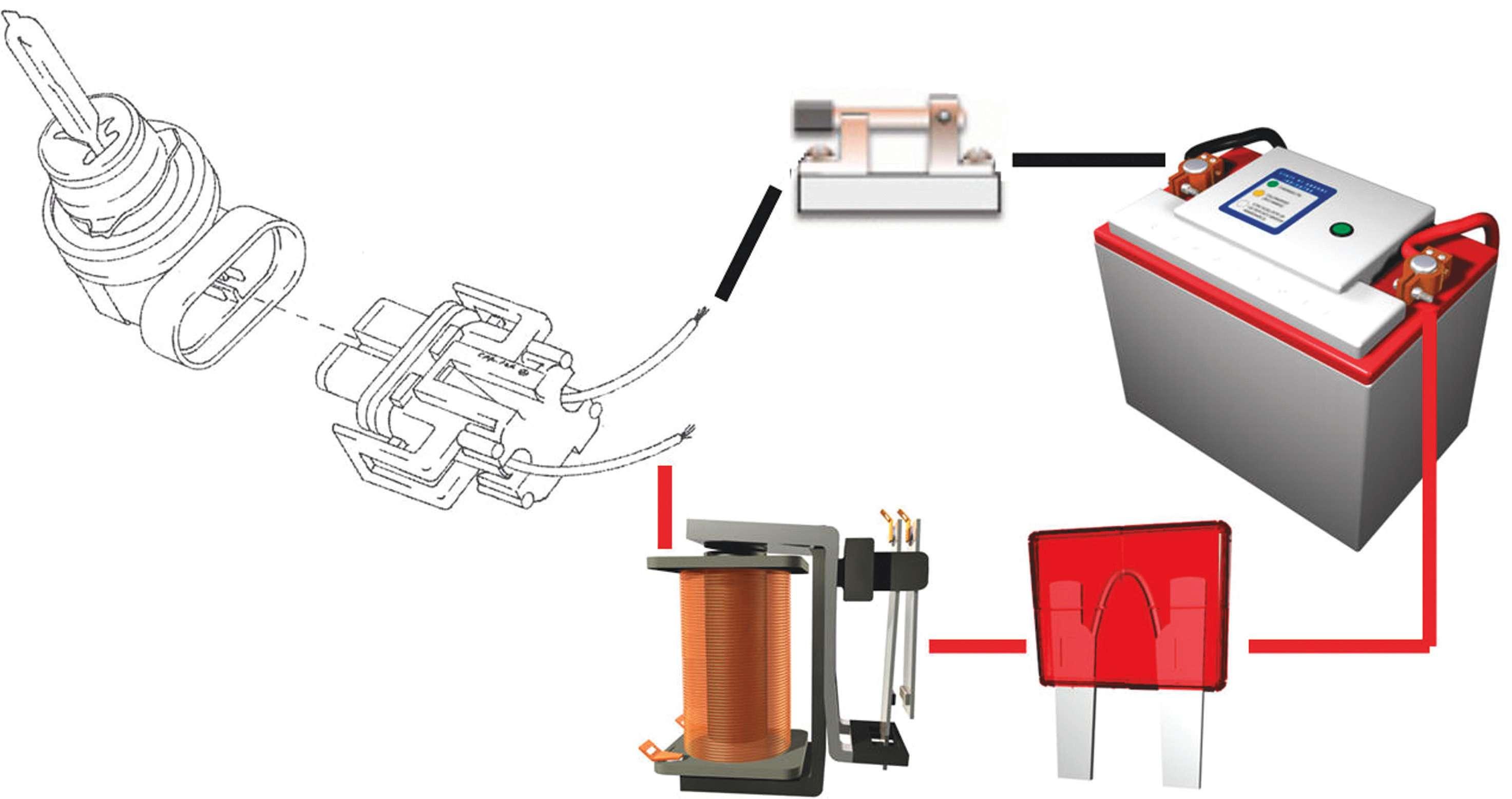
Figure 1: A theoretical headlamp circuit where the bulb is dim, even after it’s replaced.
bad, we might get a reading of 10 mV on the feed side and 350 mV on the ground side. Now, if the feed side of the lamp is bad, but the ground side is good, we might see 350 mV on the feed side and 10 mV on the ground side.
If there is a voltage drop, the likely culprits are corroded battery terminals, dirty grounds and components that internally have deterioration.
The beauty of voltage drop testing is that to isolate the cause of the voltage drop, all we do is take our lead and move it from component to component until the reading changes. If it does, we’ve isolated our problem.
2000 GMC Safari: No-code stall-out
This 2000 GMC Safari with a 4.3L V6 came into the shop with an intermittent stall situation (see Figure 2, page 30). These were some real good customers with the patience of saints. Usually, the nice ones never get away easy. The owners of this vehicle were no exception.
The diagnosis began with a DTC checkup, but there were no fault codes in the PCM or TCM. So, we started with the basics. This vehicle had a good battery and a good charging alternator, and we removed the terminal ends to the battery to boot to get a closer look. Why? GM vehicles tend to have loose side battery terminals, which cause a voltage drop, which may cause a stall out. This vehicle had some corrosion, but the terminals were tight. The terminals were cleaned up and we moved on.
Before taking any long road tests it is wise to check Mode 6 for any failures, because if something obvious is acting up, we can test that f rst before we go crazy. What we found was that the EGR reported some failures. Now it was time to check EGR operation using the scan tool to see if the component needed to be replaced.
Remember, the EGR position should be 0% at idle. Using our scan tool’s bidirectional controls, we can activate the EGR pintle and command-open the EGR. Bidirectional controls allow the user to command the EGR valve from 10% to 100%. When the EGR is open at 20%, the engine should start poorly and close to 30 KOER should cause the engine to stall.
On this vehicle, we kept opening the EGR to 50% and it did not stall. EGR valves tend to fail on these vehicles, but before we do a replacement, it’s recommend to perform an EGR cleaning of its passages even though the EGR might intermittently be bad electronically. So, we did this and there was no change.


We then decided to change the EGR and after this, the vehicle reacted normally when the EGR position was changed with the scan tool. We considered the vehicle “f xed,” because now nothing was failing in Mode 6, and we returned the vehicle it to the customer. But, it still stalled.
Now, we had to try duplicating the stalling issue and take measurements. It’s important not to throw parts at a car out of desperation. Before replacing a part, at least have evidence of it failing, because it’s easy to get lost in the forest of parts. As we were to f nd out with this vehicle, a vehicle can have several demonstrable problems and even after having them corrected, still have the symptom you’re chasing.
We took out the dog house and got started. Fuel pressure was at 56 psi with the engine running, cam and crank were on sync and the vehicle had a strong spark. The customers informed us that the truck would stall hot or cold, on idle or driving but it was very intermittent. For example, it would go days without stalling over hundreds of miles and then later it would stall three times in a few miles.
Using a labscope
The best tool to use to f nd intermittent problems like this is a labscope. Using a labscope we are able to check powers, grounds, signal voltages, and catch signal drops or voltage drops in the act. Simply connect to the signal or ground of as many suspect components as possible and put your labscope into movie mode. This way, when the event happens, you can replay to yourself what occurred (see Figure 3, page 30).
First, we put a lead into the power side of the number one fuel injector to simply see if the fuel cut out before any other event. Likewise, we connected to the ignition coil to see if spark cut out before other events occurred. For similar reasons we also connected to the crank sensor, cam sensor, TPS, IAC, EGR and ignition switch.
We started driving the truck around and when the problem occurred we noticed that when the engine stalled all the signals

would shut down at the same exact time. Powers and grounds were good and there were no signs of a voltage drop on the scope. After the engine stalled, it would start right away with no hesitation at all.
We looked into wiring diagrams to see what would cut power out to so many components at the same time. What we found was that the “Eng 1” wire (which we now connected to a pink wire in the fuse box) sends power to the fuel injectors, EGR, purge solenoid, cam sensor and ignition module. We theorized that all of these events occurred simultaneously because of a wire on that circuit.
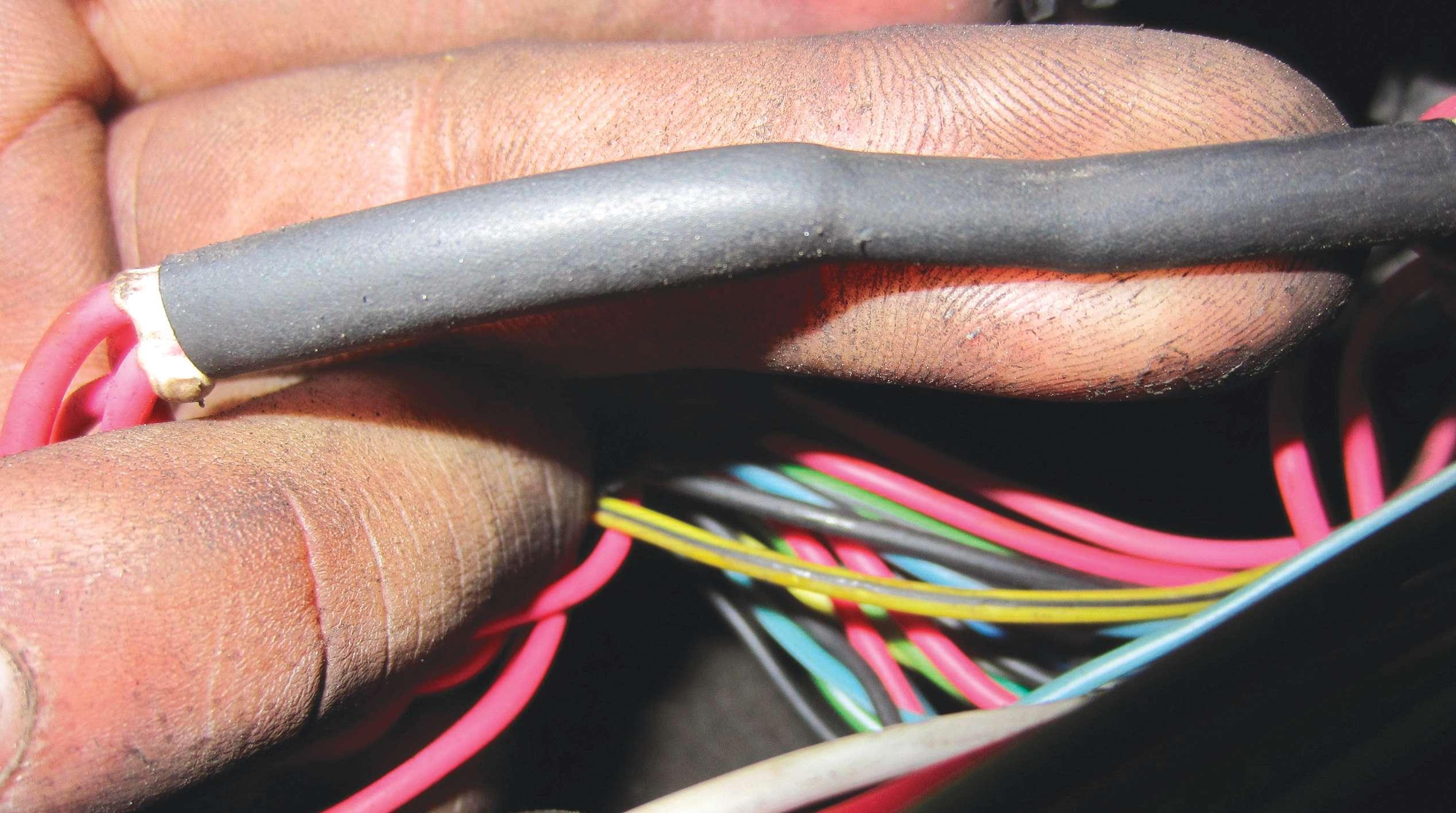
When the vehicle stalled next, it appeared that power dropped out on the Eng 1 wire f rst. So, we inspected the wire and we found a voltage drop culprit! We found a wiring splice that looked irregular, so we theorized that when the wires moved
Figure 4: Compare Figures 4 and 5, which are the suspect splice, and Figure 6 (seen on page 36), a known good wiring splice. We thought we had nailed our culprit. Figure 5. Is this suspect splice the problem? around, a loose connection inside cut power and caused the stall (see Figures 4, 5 and 6).
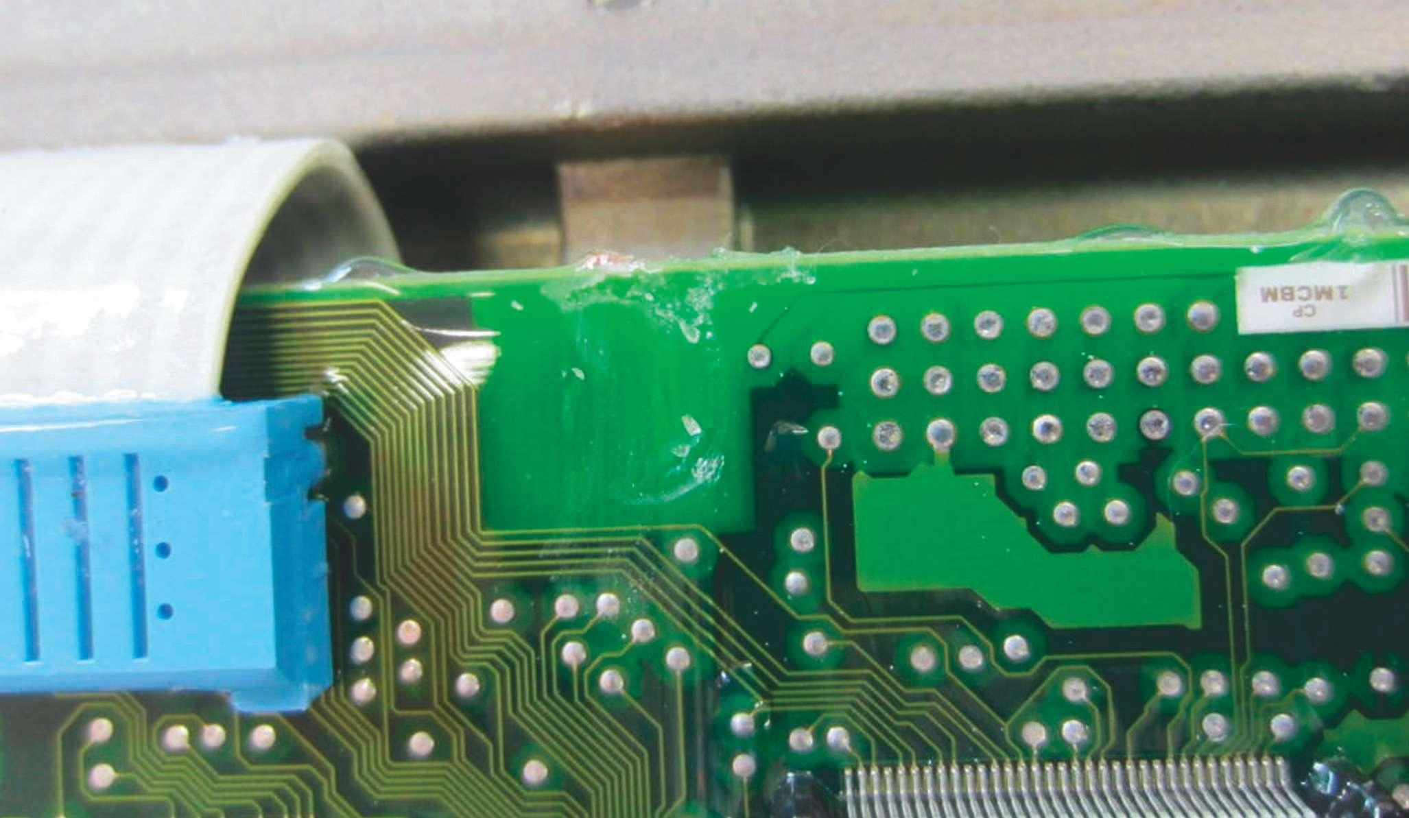
When making a new splice didn’t do the trick, we double-checked powers and grounds to the PCM. Finding nothing, we resorted to an old strategy that always served us well: take the PCM apart and look for burn marks. We found some spots of discoloration, but we weren’t so quick to replace it.
With everything hooked up with the labscope, we cut power to the PCM and watched the engine die. Everything dropped at the exact same time, like before, so we f gured the stall-out was the result of the PCM internally failing. Now, we were conf dent that a PCM was going to f x this car. (see Figure 7).
After installing a junk yard PCM and performing an anti-theft ref ash, we drove it for 200 miles. It ran great. Then, right before returning it to the customer it stalled again. It was not f xed.
Starting over
At this point, we decided to start fresh. We double-checked previous work orders and found that a fuel pump was replaced. It is hard to drive a vehicle hooked up to the fuel

pump for hundreds of miles, so that’s why supplied butt connectors. This time we cut we hooked up to the number one fuel injecall four wires, power, ground and fuel level, tor. Now, it was time to stop being lazy. re-wired all of them with special connectors First, we checked powers and grounds to that not only had solder in the middle that the pump. When we did a voltage drop test, melts when you heat the shrink wrap, but we found over a 200 mV voltage drop on the they also get crimped to boot. This makes power side and nothing on the ground side. a better connection, especially in an area where the wires might f ex. After we rewired all of the fuel pump connections, on a hunch we checked the ground even though it didn’t have any voltage drop at all. Why? Because we still wondered how 200 mV or so was enough to cause the vehicle to stall. We noticed that the ground pin at the conFigure 6. A known good splice. Compare it to those on page 34. nector was corroded. On the labscope the ground would be at 0V where it belonged, but when manipulating the connector it would rise. On a 4.3L V6, the fuel pump needs every bit of power it can get or fuel pressure drops. For example, the vehicle runs great at 56 psi but at 50 psi the engine won’t even start, because the poppet fuel injectors are made to work under a specif c fuel pressure. Figure 7: Note the white spots on the upper left. Discoloration on So, we f xed this computer boards is very common within defective modules. connection, as well as cleaning up the ground
It’s supposedly “bad,” sure, but bad enough bolts on the frame and returned the vehicle to stall the engine? It wasn’t stalling when to the customer. The vehicle now has been we took that measurement! driving a year without stalling.
At this point we were desperate and The important thing about working on decided to drop the tank and repair the a vehicle like this is to always go back voltage drop. How can it be that the fuel and check previous work, even though pump can be the cause of everything when you might think that you did a good job. it ran at 56 psi and it was only a year-old This problem would have been solved if we
Delphi unit, which is the OE application for would have scoped the fuel pump assembly that vehicle? right at the fuel pump. We learned the hard The voltage drop was created by the way never to estimate voltage drops. ●