
20 minute read
Technical

from Auto Service Professional - December 2019
by EndeavorBusinessMedia-VehicleRepairGroup


©GETTYIMAGES.COM/AGOR2012
Service technicians share tricks of the trade
SSharing diagnostic and repair information silence the noise if the explate is indeed cracked provides a real-world aid to all technicians. and causing the noise. Rather than nding a x and keeping it a secret, Jordan Hill by sharing, everyone bene ts. ere’s enough work CoAuto out there for all shops, so it isn’t a matter of safeguarding tips or tricks from a competition stand- WHEEL TORQUE point. By helping each other out, the industry ben- is subject has been discussed for years, but it e ts as a whole. anks to those who pitched in. bears repeating. Especially when you’re dealing with alloy wheels, it’s important... no, actually CRACKED FLEXPLATE? it’s vital... to tighten the wheel fasteners (nuts or e next time you are chasing an engine noise bolts, depending on the vehicle) in the proper and suspect that the explate may be cracked or sequence in order to evenly spread the clampbroken, try this idea. ing loads, and to tighten to speci ed value with While the engine is running, spray WD40 a quality torque wrench. into the bellhousing through a transmission plug I don’t care how much of a rush you might be or inspection cover. e WD40 will immediately in to get the vehicle o the li , take the time to 16
use a torque wrench. Uneven and/or under- or over-tightened fasteners can easily cause wheel hub and brake rotor hat distortion, which can lead to brake pulsation and a bouncing brake pedal. In other words, do it right.
If you end up having a brake issue a erwards, at least you eliminated the variable of improper wheel fastener tightening. Never use an impact gun to tighten wheel fasteners! Tightening with the use of a torque wrench also eliminates overtightening and the potential for over-stretched studs that can break or seized fasteners that are di cult to remove.
Larry Ritz Smitty’s Car Care
LEAKY DIFF COVERS If you run into a rear di erential cover that’s leaking gear lube, chances are that a previous service job was done carelessly by not cleaning the mating surfaces, improper tightening of the cover bolts or damaging the gasket during installation. ere’s also the possibility that the cover was warped (as a result of someone previously prying it o and bending the mounting ange), or there are gouges or pitting on the mating surface of the carrier.
Remove the cover and drain the gear oil. Take the time to inspect the cover for warp. If you can’t straighten it out to your satisfaction, pitch it and buy a new cover. Make sure that the mounting surfaces are absolutely clean and free of burrs, etc. Also, clean out all of the threaded bolt holes and clean the bolts. It’s a good idea to run a thread chaser (not a cutting tap) in each hole. Unclean threads can result in improper bolt tightening torque.
If you really want to ensure that you won’t have a comeback, apply a bead of RTV to both sides of a new gasket. I like to use Permatex “ e Right Stu .”
Install the gasket and the cover and tighten the bolts to the speci ed torque using a crisscross tightening pattern and allow it to sit for at least a few hours before adding lube. I’ve never had a leak if I sealed a cover with e Right Stu . Make sure you add the appropriate high-pressure lube additive that’s speci ed for the application.
Rob Holland Holland Service
FORD SUPER-DUTY NO-START Here are a few tips when diagnosing a Ford F-350 equipped with a 6.7L diesel engine, using a 2018 model as an example. Here are three examples of a no-start condition, involving the injector control pressure regulator, the glow plug control module and the inertia fuel shuto switch.
While cranking the engine and monitoring live data, the fuel injection control pressure switch may indicate low fuel pressure. A er inspecting the injection control pressure switch wiring and connector and nding no faults, connect a fuel pressure gauge to the fuel rail. While cranking the engine, if you nd that measured fuel pressure is below speci cation, suspect the injector control pressure switch. e regulator spring may be weak/compressed. Replacing the control pressure switch should x the issue.
Another area to suspect is the glow plug control module. First inspect the glow plug wiring harness, connectors and terminals. If no damage is found, turn the key on but do not start the engine. Using a multi-meter, check for voltage at the glow plugs. If no voltage is present, inspect the glow plug control module connector and terminals. If no faults are found, use the multi-meter to check for voltage and ground at the module. If voltage and ground are present, the module itself is faulty. Replace the glow plug module. e third example involves the inertia fuel shuto switch, which can become stuck. A er inspecting fuel and ignition components and nding no faults, connect a fuel pressure gauge. With the key on and engine o , you may nd that fuel pressure is below speci cation. Perform a visual inspection of the inertia fuel shuto switch. If no problems are found visually, use a multi-meter to check for voltage at the switch.
If voltage is present, check for voltage out of the switch. If no voltage is present out of the switch, check for continuity of the switch. If the switch has no continuity, try tripping the switch with a blow from a rubber mallet to try to reset the switch. Repeat the test. If the switch has no continuity, replace the switch.
Brian Calloway Route 20 Garage
HONDA CYLINDER DEACTIVATION We recently serviced a 2015 Honda Pilot (equipped with a 3.5L engine) that came in
with the check engine light on. During a scan, we found that DTC P3400 was stored (cylinder deactivation system, Bank 1) and P3497 (same thing, on Bank 2). We road tested and found that the cylinder deactivation was not working.
We began by checking engine oil level and oil condition but no concerns were evident.
We then inspected the cylinder deactivation system wires and connections but found no problems.
When we viewed live data we saw that the oil pressure switch was showing low oil pressure. In order to verify the reading from that switch, we removed the switch and installed a hydraulic oil pressure gauge, which showed that engine oil pressure was within the speci ed range.
Using a multi-meter, we measured the original oil pressure switch continuity and found that the switch had no continuity. Simply replacing the switch and clearing the codes did the trick. Cylinder deactivation worked and the check engine light never came back on.
Bill ornton Bill’s Place
HONESTY AND A SIMPLE FIX Chrysler PT Cruisers are notorious for this problem: We had a customer bring her 2005 PT into the shop in a panic because she thought she had a severe problem. She said that every time she went over a bump, she heard a loud banging noise from the rear. Her boyfriend told her that the rear struts had broken and that the rear wheels would fall o if she didn’t get it xed right away.
Well, for one thing, the PT Cruiser has rear shocks with coil springs, not strut assemblies. Of course, the problem was simply the Watts link “bell crank” bushing was worn out, which certainly wasn’t going to allow the wheels to fall o . A $46 part and about 30 minutes of labor easily solved the issue.
A worn Watts link bell crank can cause a loud thump or banging noise, which can make someone assume that there’s a major problem with the rear suspension, such as a broken shock or a failed “strut.” She was thankful that we were honest about it and she was thrilled to pay the bill, which was a lot less than she had feared it would be.
About an hour and a half a er she le , she had
A worn-out Watts link/dog bone can create a very noticeable banging noise that can easily lead a customer to believe that a serious problem exists with the rear suspension.

two pizzas delivered to the shop to say thanks. We assume that she’ll never let her boyfriend work on the car.
Lee Monroe Lee’s Total Service

FORD TRUCK WHINE Sometimes, strange noises are di cult to track down. Our shop recently took in a 2017 Ford F-350 Super Duty with the 6.7L diesel engine, which had 25,000 miles. e owner complained about a whining noise but he wasn’t sure where it was coming from.
We found that the noise was coming from the fuel tank’s in-tank pump. We connected a fuel pressure gauge to the fuel rail, which showed that fuel pressure was de nitely below speci cation. We then connected the fuel pressure gauge to the fuel lter inlet line and saw that pressure was within spec.
It seemed obvious at that point that the lter was clogged/restricted, which was causing the fuel pump to strain and make the whining sound. We replaced the fuel lter and the problem disappeared.
Ernie Blaylock Forest Auto
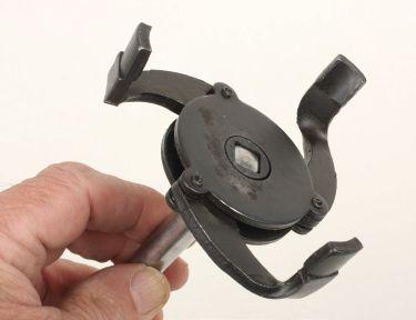
A cam claw-type filter wrench allows easy access to oil filters that are difficult or impossible to service with a band-type filter wrench.
DON’T WASTE TIME When servicing a late model Kia Soul, you’ll find that there’s a large black plastic belly pan under the engine. There’s no need to remove this pan in order to perform an engine oil change. Depending on the year, some (an example is the 2016) have plastic snap-in caps that, when removed, allow access to the filter and the drain plug. Newer 2020 models, for example, simply have open holes in the under-engine plastic pan (no caps to remove) with a large hole under the filter and a smaller hole toward the passenger side under the drain plug.
With the plastic pan in place, you won’t be able to use a cinch-type filter wrench, but a universal 3-jaw self-adjusting claw-type wrench, along with a ratchet and extension, allows easy filter removal.
The access hole under the filter is large enough to allow you to hand-tighten the filter (since they should only be hand tightened anyway). The oil pan drain plug requires a 17 mm socket and a 4- to 6-inch extension on the ratchet.
Yes, with the cover pan removed, everything is readily accessible, but there’s no need to spend the extra time required to remove that cover pan if you’re simply performing an oil and filter change.
Mike Hendrickson Avalon Premier Service
PAD AND CALIPER LUBE Most disc brake systems you encounter feature a “moving” caliper, either a floating caliper that 20
The claws are designed to close and grip onto the filter when turned counter-clockwise. This type of filter wrench has been around for decades but is increasingly needed on many of today’s engines due to filter location.
rides in/out on a pair of pins, or sliding calipers that move along stainless steel inserts. In order to allow the caliper to move freely as designed, lubrication is critical to prevent caliper hang-up or dragging pads.
On floating calipers, during a brake job remove the pins and their rubber boots from the caliper — don’t just check them for sliding and assume they’re OK. Clean the pins thoroughly. If any wear or rust is evident, replace the pins.
Apply a thin coat of a dedicated brake/caliper grease to the pins. Avoid the temptation to use just any grease that you may have in the shop. To be safe, only use a dedicated brake/caliper lube. Examples include Permatex Ultra Disc Brake Caliper Lube or CRC Synthetic Brake and Caliper Grease.
These lubes are synthetic, designed for high temperature and are plastic and rubber safe. They won’t melt, freeze or wash out and are specifically designed for disc brake caliper use.
outer tabs. Rather than simply replacing pads and either resurfacing or replacing the rotors, pay attention to the details in terms of how and where the calipers and pads move along their respective surfaces.
A little bit of lube goes a long way, and obviously avoid excess lube that may contact the rotor and/or pad friction surfaces.
Properly cleaning and lubricating the critical surfaces on oating or sliding calipers is a basic part of brake service, but in some cases, the installer may take shortcuts by only performing a quick inspection and assume that the moving surface areas are OK.
Take the time to complete the brake job by paying attention to all moving/sliding surfaces to avoid potential customer complaints that can include dragging pads, uneven braking, premature pad wear, etc.
Alan Flickinger Montrose Motors
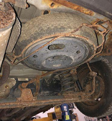
DON’T IGNORE THE SPARE Whenever you have a customer SUV, CUV or light truck on a li performing service work, check to see if the vehicle has a spare wheel/tire underneath that is held by a bracket and cable. is type of spare carrier allows the spare to be lowered with the use of a wheel lug wrench, with the drive usually located in the rear hatch oor trim area or via an access hole in the rear bumper area.
With long-term exposure to the elements, if it hasn’t been disturbed for a while, rust buildup can make it di cult to lower when and if the customer experiences a at tire and needs to access the spare. e threaded drive might be rusted, or the support cable may have rusted and snapped, etc.
To make sure the spare carrier is in working order, try lowering and raising it. If you encounter di culty, apply penetrating lube, lower it and remove the spare. You can then clean and lubricate the carrier so that it works smoothly. Reinstall the spare and raise it back up to the stored position.
Naturally, if the carrier requires this service work, obtain the customer’s permission rst so they’re not surprised with any extra charges. All too o en, the spare tire carrier is ignored. To avoid having the driver stranded somewhere be22
Ignored spare tire carriers can become rusted and dif cult to lower. Apply penetrant lube to the threaded adjuster and run the threads up/down to make sure it functions.
cause they couldn’t remove the spare wheel/tire, make sure the carrier is in working order.
We once had a Ford F-350 in the shop, a er the customer experienced a at. When he attempted to grab the spare, the carrier system was so badly rusted that it wouldn’t budge. We ended up having to cut it o and replace it with a new carrier. e truck was seven years old and the spare carrier hadn’t been touched since he bought the truck. Road salt and moisture simply made it unusable. is cost the customer $180 for the new carrier plus an hour and a half of shop labor, which could have been avoided if the carrier had been checked and lubed previously.
Granted, not all vehicles have a spare these days, but it’s common on many utility vehicles and light trucks.
Mike DeTunno Marks’ Complete Auto Care
SUPER DUTY FICM SYNCH On Ford Super Duty diesel trucks, a no-start may be accompanied by codes P2614 and/or P2617 (cam and crank position sensor codes). e FICM (fuel injection control module) reads the synchronization of the signals from the cam and crank sensors to deliver fuel in proper timing.
We more commonly see issues of damaged/ loose sensor wiring than bad sensors.
GET THE JOB DONE WITH FLEXZILLA® AIR TOOLS Let Us Be Your Parts & Equipment Supplier


www.oreillyauto.com/professional-catalogs
PRO MINI IMPACT WRENCH
The Pro Mini Impact Wrench has 800 ft-lbs. of breakaway torque and an extremely lightweight design. Features an ergonomic grip with a patented forward/reverse toggle switch and torque selector that allows easy one-hand operation. LEG AT1475FZ
PRO REACTIONLESS MINI AIR RATCHET KIT
Get in tight spots and get the job done with the Flexzilla Pro Reactionless Mini Air Ratchet. The reactionless clutch prevents kickback. The compact and lightweight design is perfect for small workspaces like under automotive dashboards. LEG AT8535FZ
MAKING IT FASTER AND EASIER THAN EVER TO ORDER PARTS PRO RECIPROCATING MINI AIR SAW KIT
Cut through the toughest materials with the Flexzilla Pro Reciprocating Mini Air Saw. The lightweight, compact design and low vibration reduces operator fatigue during extended use. Plus, its high-speed, strokes per minute, allows you to cut through the toughest materials with ease and comfort. LEG AT8565FZ
AIR HOSE
Flexzilla is a revolutionary hose featuring a flexible hybrid polymer material that redefines flexibility. • Does not kink under pressure • Lightweight and easy to handle • Lays flat, no memory
FIRSTCALLONLINE.COM Visit our website for a complete, internet-based catalog designed exclusively for the Professional. ADV 1492
First of all, check battery condition. The FICM needs to see proper high voltage. If the batteries are weak, the synch won’t be correct. If your synch is off, first check to see if you have engine rpm reading on the tach. If you have rpm reading, the crank position sensor and its wiring is likely OK, which leads you to suspect the cam position sensor or its wiring.
The cam sensor wiring comes out of the main loom next to the fuel filter. Perform a wiggle test. If you have intermittent start/no-start while wiggling the wire, you have confirmed bad wiring.
Disconnect the cam sensor connector (down low on the driver side) and feed the wire up. There may be a small clip on the wire to the block, so be aware of this while fishing out the wire.
Carefully expose the wire where it enters the main harness to avoid cutting other wires. Using a new pigtail replacement wire with connector, solder the connection and wrap with tape. Replace the original aluminum foil wrap and split conduit. If you need to replace the sensor itself, stick with an OE Ford or reputable known-brand sensor. Some bargain-priced sensors won’t allow proper voltage.
Mack Harden Stow Auto
CHECK THE OBVIOUS When a vehicle comes into the shop with a nostart issue, you will likely inspect the air intake system and ignition system. If you find no faults, you may check the fuel pressure and may find that pressure is within spec.
If you disconnect a high pressure fuel line and command the fuel pump to dump fuel into a container and find that measured volume is below spec, look at the fuel tank. If the tank has been damaged and a dent/deformation is found, this can prevent the fuel from getting to the fuel pump.
In this case, obviously you need to replace the fuel tank. If you suspect a fuel delivery issue, before you spend lots of time diagnosing components and circuits, take a look at that fuel tank.
Glen Stromberg Big Mountain Service
MAZDA TRANS We recently had a 2015 Mazda Miata equipped with an automatic transmission in the shop for a no-forward and no-reverse issue.
After checking for codes and finding no immediate issues, we monitored turbine sensor PID and VSS PID with the engine running and the transmission in gear.
If the turbine sensor PID shows turbine sensor operation and VSS does not, we have a possible transmission malfunction. If both the turbine sensor PID and VSS PID show operation, we have a possible final drive or drive axle malfunction.
If the turbine sensor PID shows no operation, check for stripped transmission input shaft splines. Remove the trans and check the input shaft and torque converter. Perform a line pressure test.
If the ATF is contaminated and pressure is correct, inspect for friction material and metal particles in the fluid.
In our case, we found stripped input shaft splines, which meant replacing the input shaft, at which time we performed a transmission rebuild at the owner’s request.
If you wish to perform a trans range switch resistance test, here is the procedure: 1. Disconnect the battery negative cable from the battery and unbolt the catalytic converter front bolts and move aside. 2. Remove the under-trans insulator. Use a DMM to test the switch. 3. With the key off, disconnect the 9-pin TR sensor connector (located at the passenger side of the transmission case). 4. Probe across the sensor pins. Move the shift selector through each range position. 5. Resistance should be less than 0.1 ohm in the appropriate range. - Park............pin E to pin B - Reverse......pin E to pin C - Neutral......pin E to pin H - Drive..........pin E to pin D (resistance should be open line in other ranges) 6. Re-assemble.
Alan Kneifer Randy’s Total Service
FORD 6.0 DIESEL TIPS Here are a couple of tips when dealing with a 2003-2007 Ford Super Duty equipped with the notorious 6.0L diesel engine.
Whenever servicing this truck, inspect the plastic radiator tanks for hairline cracks. These
will eventually open up and allow a nasty high pressure leak. While some cracks may be repairable, replacing the radiator is the best way to go.
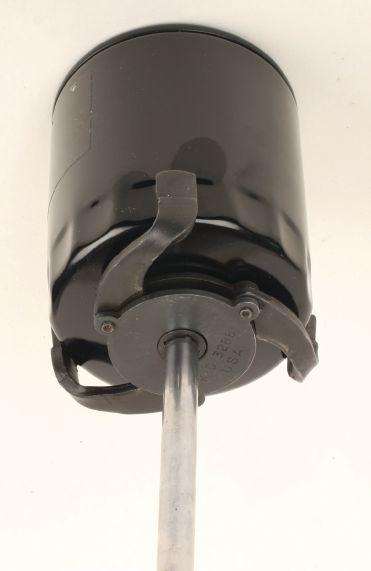
Also, if the truck is equipped with an automatic transmission, note that there is a remote transmission fluid filter. This is a canister style filter located under the front bumper passenger side, below the A/C compressor.
This remote filter is often ignored, as some folks don’t even know it exists. This filter should be changed out every 30,000 miles or so. The filter cartridge is inside an aluminum housing that features a 22 mm hex at the bottom.
This housing is threaded in place, but do not use a hand wrench to break it loose, as you’ll end up placing twisting pressure on the lines and bracket. Instead, use an impact wrench with a 22 mm socket to break it loose. Once broken loose, unthread the housing by hand. Then pull the filter cartridge out.
You will notice that the filter bottom has a cap with a small center spring. You need to re-use this lower cap and spring. If it’s not on the filter cartridge, check the inside of the filter housing, as it may have fallen off of the filter during removal of the housing.
Clean this lower cap and spring. Clean the upper O-ring on the upper portion of the housing that is attached to the lines, and lube the O-ring with clean trans fluid.
Motorcraft filter cartridges may not include a new O-ring, but some aftermarket filters do include an O-ring.
Insert the new filter into the stationary upper portion of the assembly, and install the lower cap and spring to the bottom of the filter. Carefully thread the aluminum filter housing into place.
Be careful, as it’s easy to cross-thread this.
Similar to installing an engine oil filter, once you hand tighten to the point where you snug up against the O-ring, turn it another 1/4-turn.
At every 30,000 miles, replace this filter, or when you’re removing the transmission pan to replace the main filter. Just don’t ignore this remote filter.
Kevin French Topper’s Truck Service
FORD ECOBOOST SHUDDER A rough idle concern is common on the Ford EcoBoost engines from 2011 to present, especially in truck applications.
One fix I’ve found is to carefully clean the MAP sensors in the intake duct and at the intake manifold.
After removing the sensors, carefully spray clean with an electrical contact cleaner (not a brake cleaning solvent!). Spray the contact cleaner to remove any oil buildup on the thermistors, allow to dry and reinstall. This may not fix all rough idle concerns, but I’ve had good luck by cleaning the MAP sensors on several of these engines. Just be sure to use an electrical-safe cleaner. Do not try to scrub or wipe... just spray until clean.
Ralph Rendano Valley View Service
MAP sensors on the Ford EcoBoost 3.5L engine are prone to oil contamination, especially the sensor at the intake manifold.
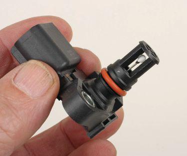
Never try to clean the sensors by touching/ wiping. Spray to clean using only an electrical contact cleaner solvent.


