ARC 501 ADVANCED ARCHITECTURE STUDIO I


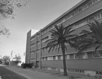
AZ / UNIVERSITY OF ARIZONA / MATHEMATICS BUILDING / CAIN NELSON & WARE / 1969 Eduardo Gonzalez and Jayani Mehta
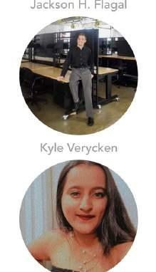
MA / HARVARD / GRADUATE CENTER / WALTER GROPIUS AND THE ARCHITECTS COLLABORATIVE / 1950 Jackson H. Flagal, Kyle Verycken and Dhwani T. Desai
MA / WELLESLEY COLLEGE / THE MARY COOPER JEWETT ARTS CENTER / PAUL RUDOLPH / 1958 Xindong Li and Yuheng Liang
NY / UNIVERSITY AT BUFFALO / DIEFENDORF HALL / DUANE LYMAN / 1963
Caleb Rutter, Julia Velimirovic and Kayla Smith

This studio will focus on adaptive reuse and expansions of existing buildings. The goal is to learn from previous constructions (avoiding tabula rasa) through new adaptations and expansions, giving them a second life with a current, sustainable and bioclimatic approach. Each professor will define a specific building typology, and the students, working in groups of three, will receive a particular case study building. The course will have four modules: (I) research, (II) reconstruction, (III) adaptation, and (IV) expansion. During the first one, the students will make contextual approaches to the overall topic (history, urbanism, technologies, geometries, materials, programs, author’s biography, etc.). In the second one, they will reconstruct all plans and relevant information on the existing buildings. During the third module, they will propose architectural adaptations, and in the final phase, they will propose an expansion with a new program.
This studio will move around the following question: What kind of architecture is necessary to support higher education in the 21st century? When studying a group of unique academic buildings on select campuses across the United States, we will review the various constraints that were faced during the surge of construction in the post-WWII era to support rapid increases in academic enrollment and space. The goal will be to propose expansions, modifications, and new educational and public architecture to philosophically and physically reinvent higher education to support the 21st century learning landscape.
Assignments are broken into five distinct modules. In addition, the seven graduate studio’s Comprehensive Design Principles and Respective Learning Outcomes (NAAB/ASU) are distributed among them: Equity/Justice, History/Culture, Context/Environment, Program/ Wellbeing, Technology/Innovation, Construction/Practice, and Representation/Integration.
What is the big idea behind this project and how did the approach towards sustainability inform the design concept? Specifically explain how the design is shaped around the project’s goals and performance criteria, providing utility, beauty, and delight. How does the project engage all the senses for all its users, and connect people to place? What makes this building one that people will fight to preserve? Give examples of how individual design strategies provide multiple benefits across the full triple bottom line of social, economic, and environmental value.
Sustainability is inextricably tied to the wellness of communities. Describe specifically how community members, inside and outside the building, benefit from the project. How does this project contribute to creating a walkable, humanscaled community inside and outside the property lines?
Sustainable design protects and benefits natural ecosystems and habitat in the presence of human development. Describe the larger or regional ecosystem (climate, soils, plant and animal systems) in which the project is sited. In what ways does the design respond to the ecology of this place?
Sustainable design conserves and improves the quality of water as a precious resource. Illustrate how various water streams flow through the building and site, including major water conservation and stormwater management strategies. Describe strategies to reduce reliance on municipal water sources. Does the project recapture or re-use water?
Providing abundance while living within our means is a fundamental challenge of sustainability. How does the project provide “more with less”? Possibilities include “right sizing” the program, cost-effective design decisions, economic performance analysis, economic equity strategies, notable return-on-investment outcomes, contributing to local and disadvantaged economies, etc.
The burning of fossil fuels to provide energy for buildings is a major component of global greenhouse gas emissions, driving climate change. Sustainable design conserves energy while improving building performance, function, comfort,and enjoyment. Describe any energy challenges associated with the building type, intensity of use, or hours of operation, and how the design responds to these challenges. Describe energy-efficient design intent, including passive design strategies and active systems and technologies. How are these strategies evident in the design, not just the systems?
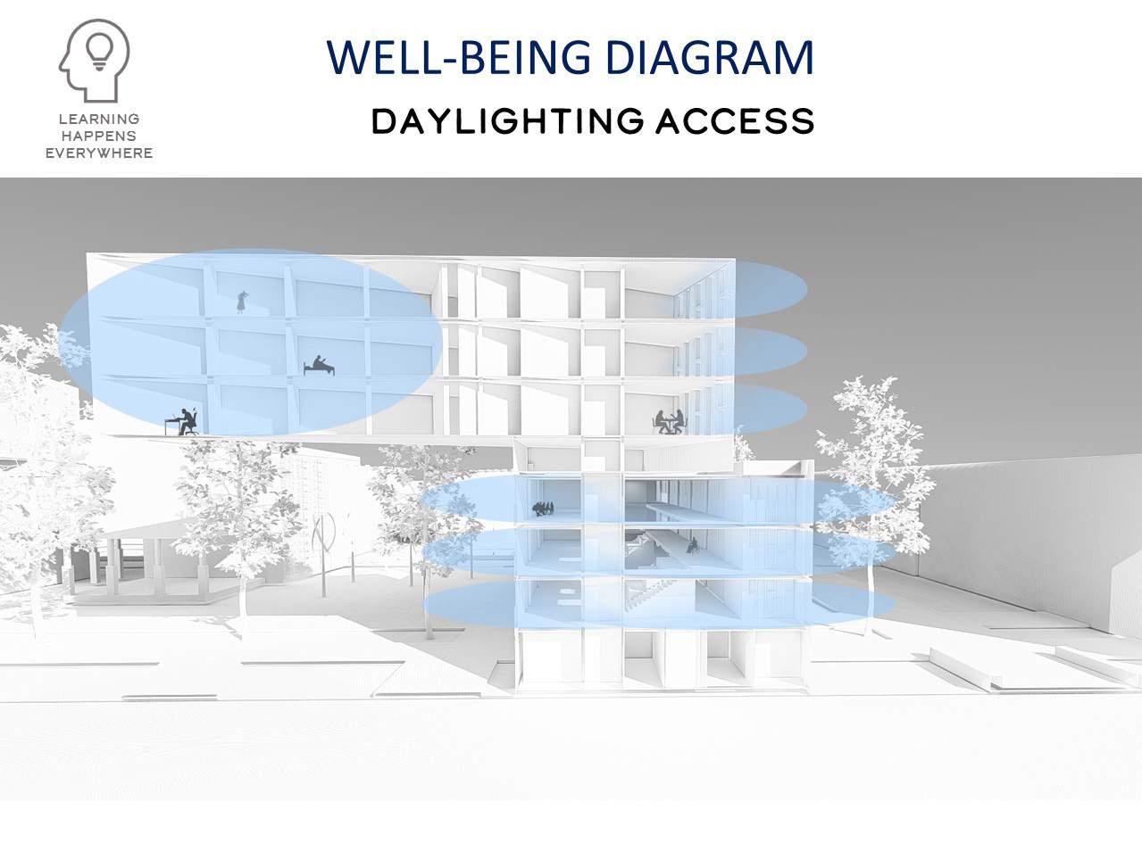
Sustainable design supports comfort, health, and wellness for the people who inhabit or visit buildings. Describe strategies for optimizing daylight, indoor air quality, connections to the outdoors, and thermal, visual, and acoustical comfort for occupants and others inside and outside the building. How does the design promote the health of the occupants?
Sustainable design includes the informed selection of materials and products to reduce product-cycle environmental impacts while enhancing building performance. Describe efforts to optimize the amount of material used on the project.
Reuse, adaptability, and resilience are essential to sustainable design, which seeks to maintain and enhance usability, functionality, and value over time. Describe how the project is designed to facilitate adaptation for other uses and/or how an existing building was repurposed. What other uses could this building easily accommodate in 50-100 years?
Sustainable design strategies and best practices evolve over time through documented performance and shared knowledge of lessons learned. What lessons for better design have been learned through the process of project design, construction, and occupancy, and how have these been incorporated in subsequent projects?

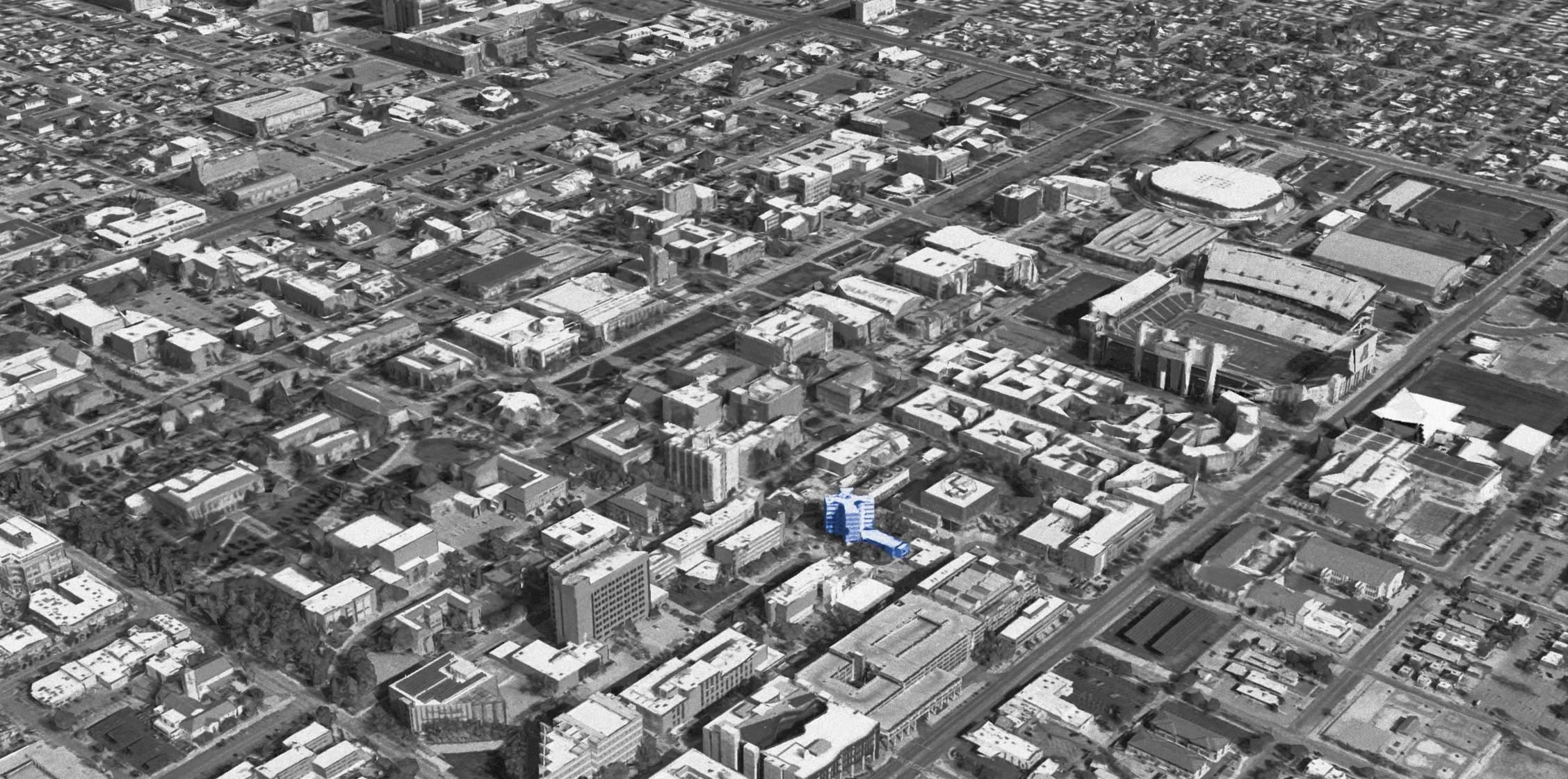
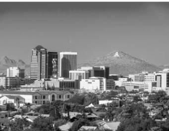
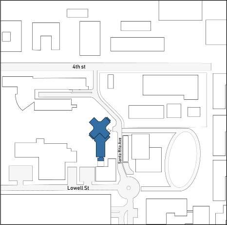
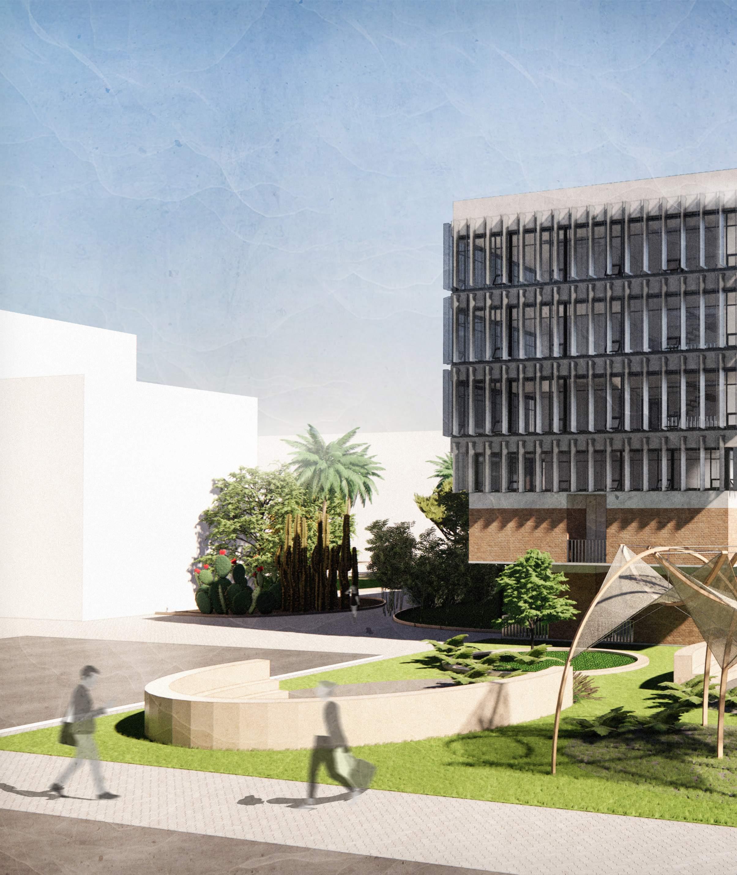
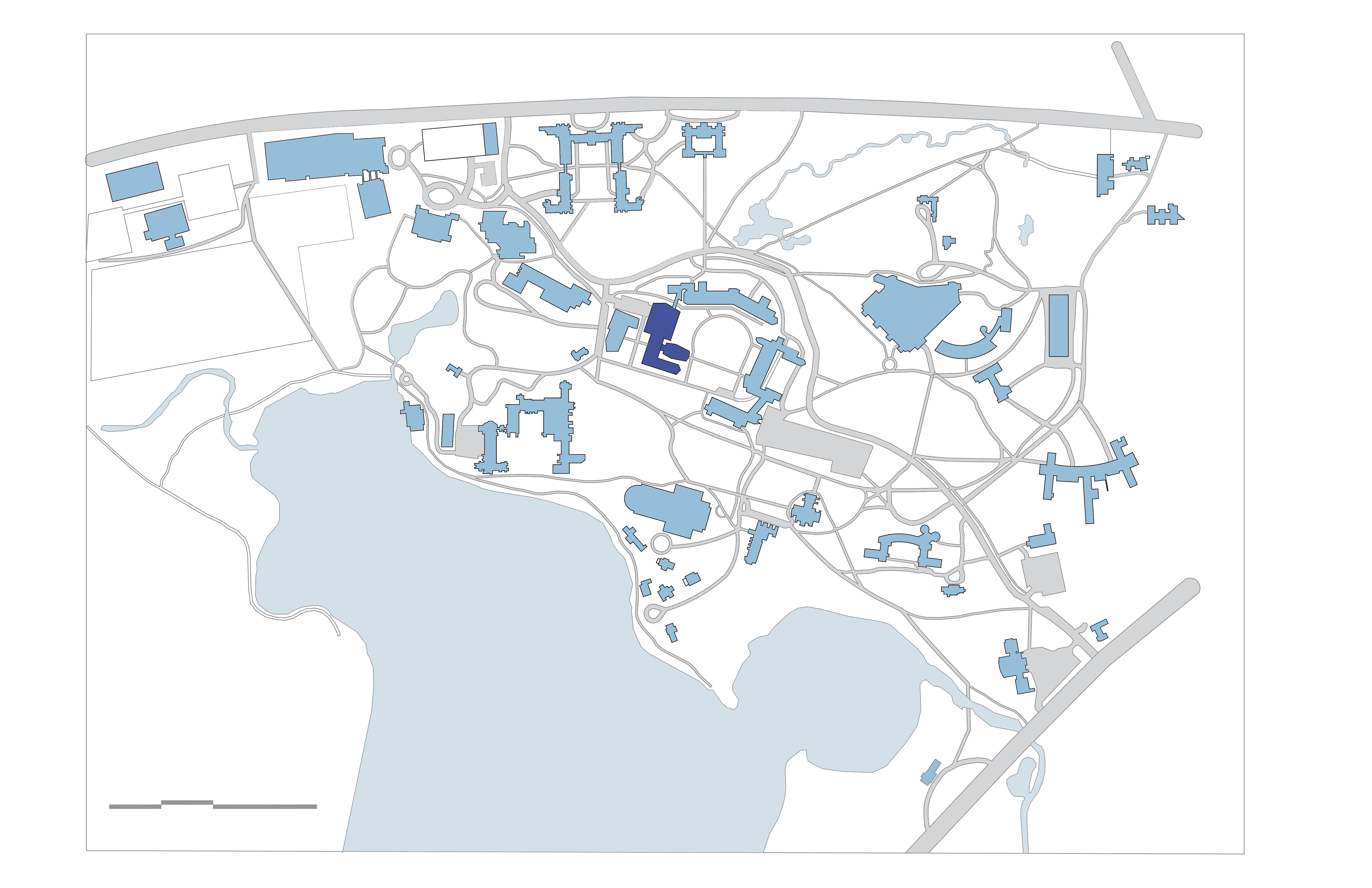
The University of Arizona is a land-grant research university dedicated to education,research, and public service. The University is centrally located in the Tucson metropolitan area, which has an estimated population of 850,000. The University is in the urban heart of the community and is surrounded by a series of predominantly residential neighborhoods.
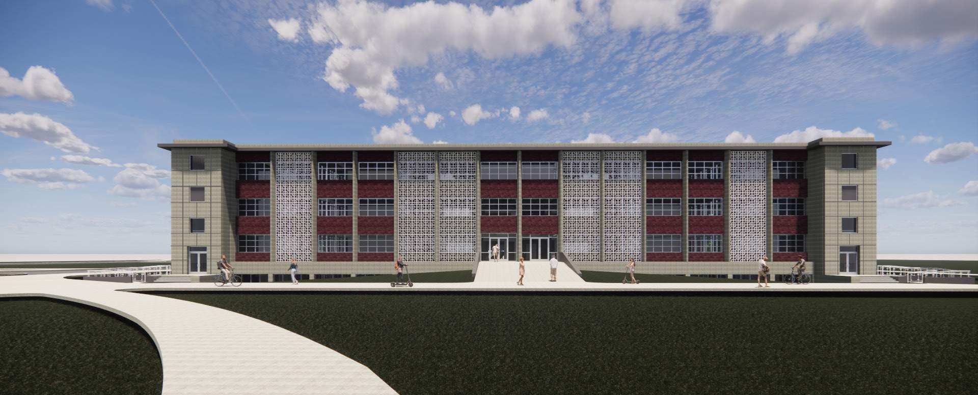
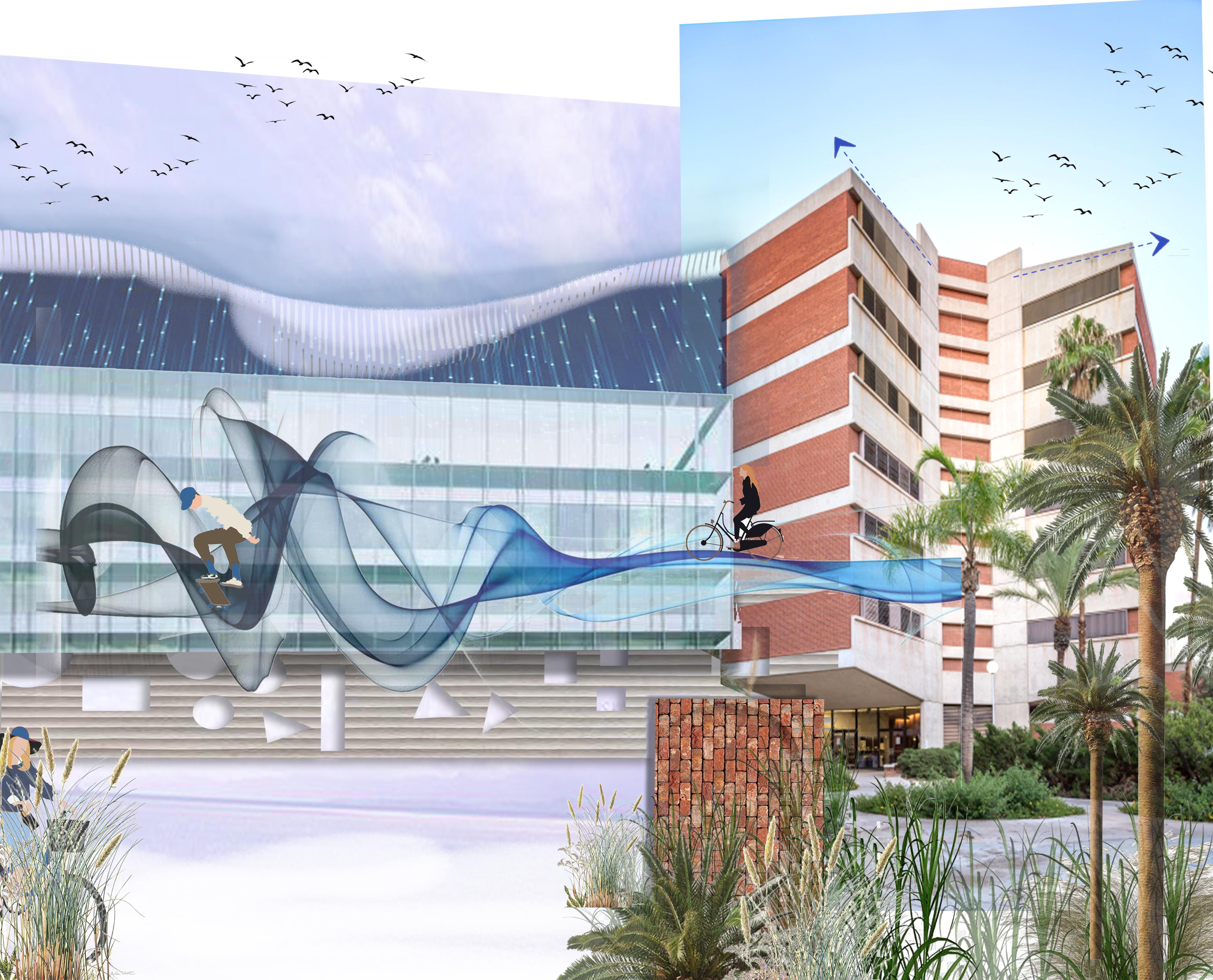
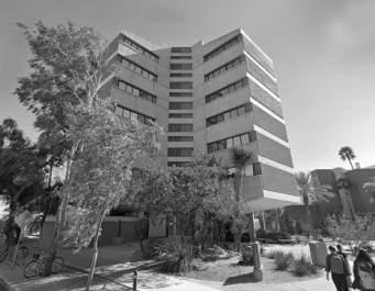
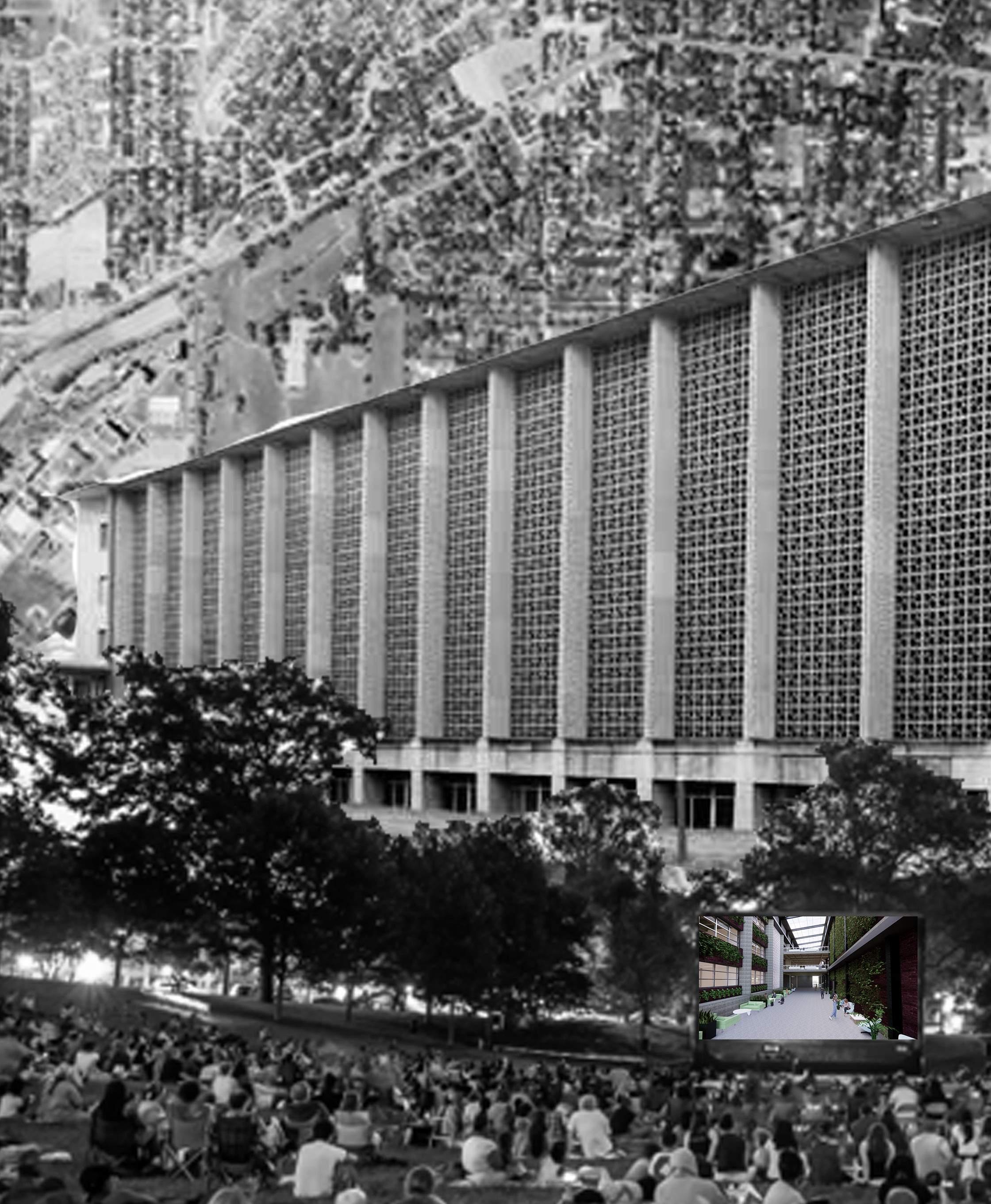
The current site of the math building sits on the newer, southern side of the campus. The building built in 1965-71 marks it style as brutalist architecture. As said building gets aged with the time so has this one. With the changing needs of educational environment this proposal focus on the adapting the existing building and using it as the base to cater the newer needs of the time.
The newer vision focus on incorporating more of student activities with collaborative spaces for multidisciplinary activities to occur in the building.
On the other hand expansion solely focus on evolution of the student arena which provides with more visual connectivity with the surrounding science core as the green belt prevailing on the site. The design tends to provide new identity to the campus by creating the pause points at the gateway points.
It tries to connect and wrap all the activities around the building by juxtaposition the newer expansion.
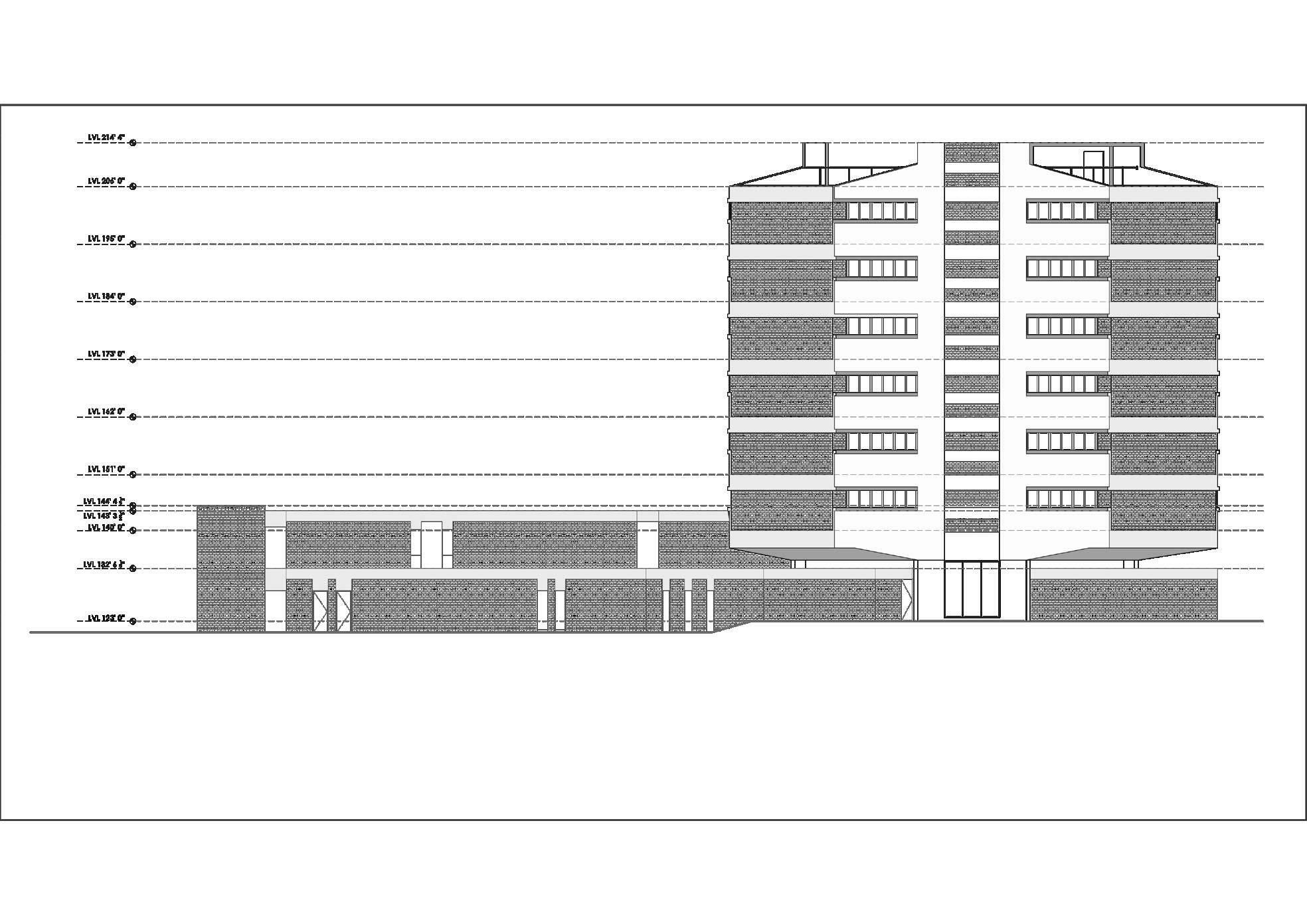
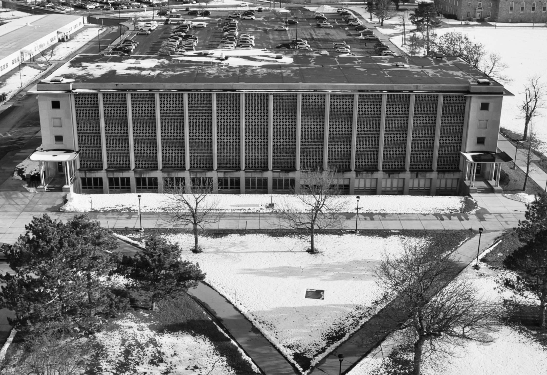
The 7 story Mathematics building in Tucson, Arizona is utilized by a campus of nearly 50,000 enrolled students every year. It is a building on the campus that contains many labs, classrooms, and seminar rooms
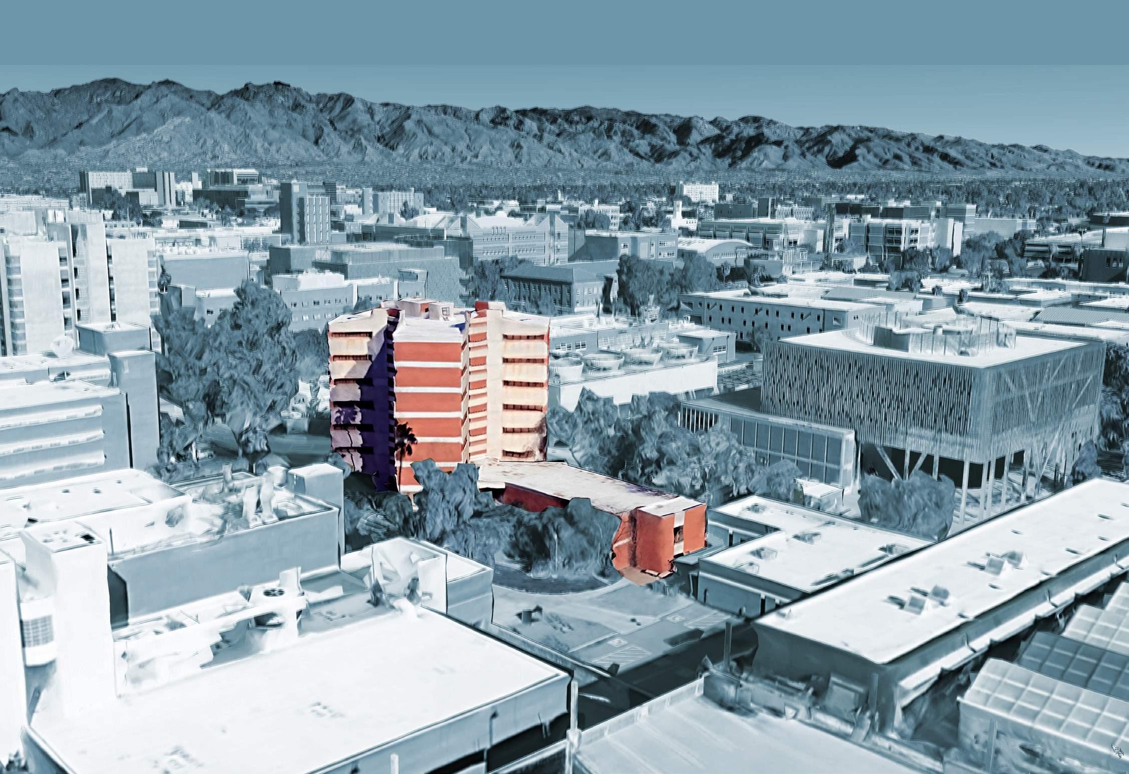
for students. This building also hosts students in linguistics and other smaller departments as well. It is located in the southern part of the University of Arizona campus. It was heavily inspired by the work of

As the campus continued to grow after its opening in 1891, more buildings were added around the historic buildings in all directions. Some of
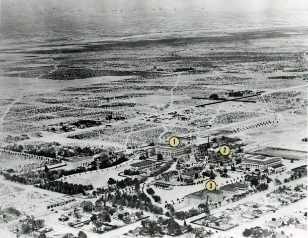
the historic buildings still stand today. The current sit of the math building sits on the newer, southern side of the campus. The math building connects
to the 6th street which is main street near the south entry of the building.
The old main acts as the nuclei which has earlier the style of traditional buildings. Other buildings around it which expanded and were built on
the later phases were of brutalist architectural style predominantly using the bricks, concrete structure as their vocabulary. The science core around
the math building forms the strong character of brutalist architecture with small openings and huge brick walls.
1961 Edward Nelson creates partnership with James Ware, Gerald Cain, William Cook in Tucson, AZ
1967 Ashton Company was selected to built Phase-I (Basement & 5 Floors)
1970 building addition was developed (Phase-II with 2 more floors above). A new department head was selected
1960 Ph.D. Program was created . Improvement to math department made. A building shift from physics building were developed
1965 funding approved for the math building by National Science Foundation. The project eventually was done in 2 phase.

1969 math building was opened. (Phase I with only 5 floors at the time and 1 floor on southern side of the building)
1972 construction of Phase-II was completed and opened
In new areas of campus development, (such as between Speedway and Mabel, and Sixth and Eighth Streets), a high standard of contemporary architectural excellence is required.
The selection of exterior building materials for permanent facilities should be based on long-term institutional durability and ease of maintenance; texture and textural variety; color palette; energy conservation considerations; cost and availability;
Works of art should be integrated into the design of each building, especially in building entrance areas (indoor and outdoor) and other high-use common areas.
Gateway buildings anchor strategic street intersections which mark entrances to the campus from public arterial streets. In addition, the building is key to creating an identifiable campus area for the portion of campus with which it is associated. Special attention should be given to building design and massing, landscaping, and lighting.
N
For transition zones and campus gatewaysinformal arrangements of landscape elements, either in continuous meandering pattern for linear conditions, or clustered or grove-like pattern for entry/highlight conditions


Major vistas along campus streets and open space areas these provide a linear view for pedestrians, visually organizing the open space and orienting the user; they also provide open space views from buildings facing the open space.
Visual Continuity - the design elements in open space development include planting materials; seating; surface treatments; lighting; special features such as food pavilions, transit stops, and information kiosks.
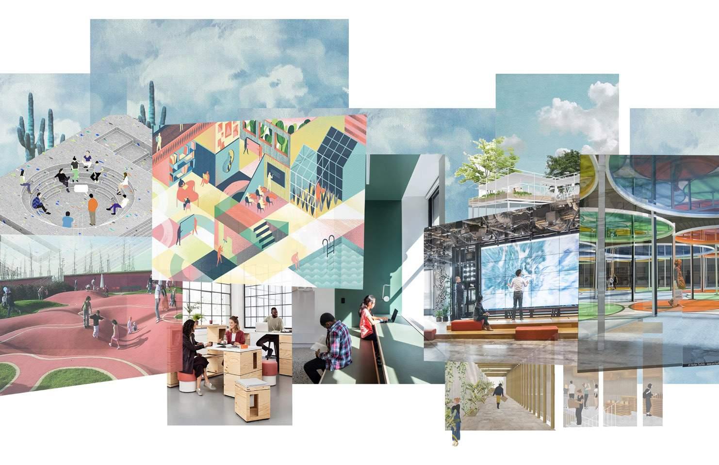
The 21st century learning environment focus on culture of learning & interactions, culture of collaboration and multidisciplinary, culture of making and culture of innovation which demands the nature of space to be same.

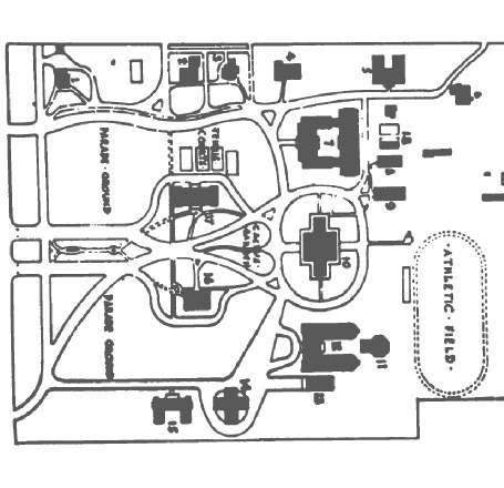
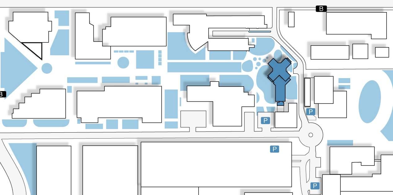
The site has evolved in terms of road networks and the science core buildings in terms of usability due to student population growth on the campus. The original site area when it was developed. Major differences in the old roads. Changes in the site over time with more non-pedestrian friendly zones on northeast corner. The current state of the site and how it sits between the updated streets
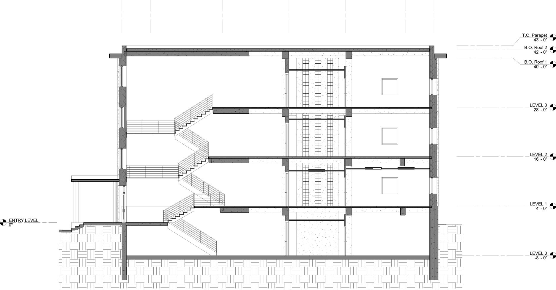
The building was made in 2 phases due to economical limitations. The first phase included making of first floor on the tail part and up-to 4 floors in the X part. Later one more floor was added on the tail part and then 2 more floors on the X part of the building.
roads.
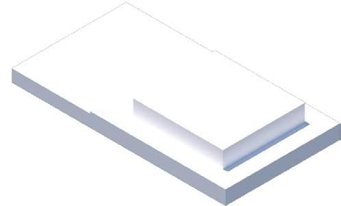
Identify the building footprint & topography close to the old math department originally in the physics building on the northwest (PAS).
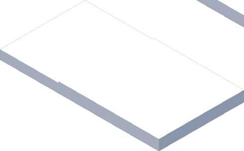
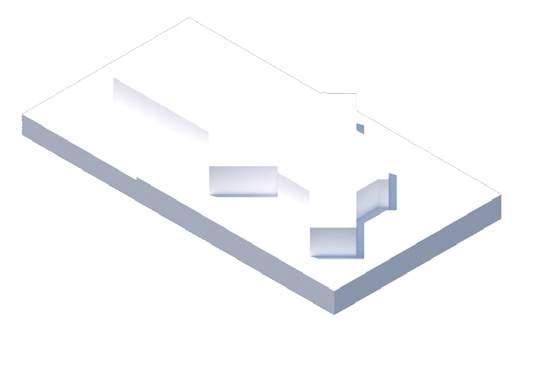
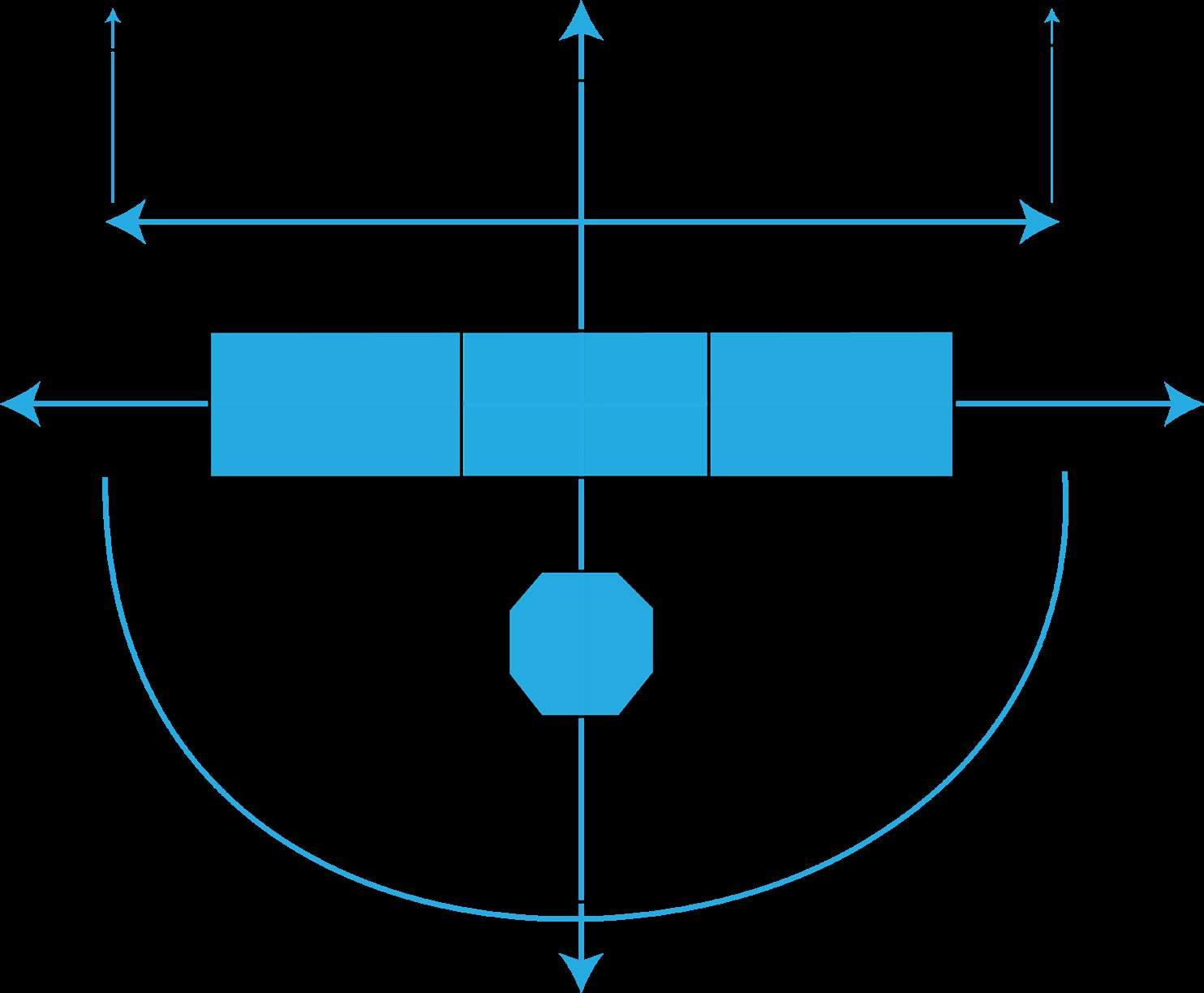
Place massing on raised side of land and center of 2 axis intersection
Funnel in students coming from the paths & roads from all directions of the campus. Utilize topography on southern side by lower ing onto the less elevated area. Orient highly active sides on the north
Cut open northwest direction to welcome students into the department from the phys ics building
The Site has contours which is respected by the level difference on the first floor. The site has 2 levels which are at approx 2 ft of difference.
The orientation of the building is north south. The tail falling at the South and X at the North direction. The entrances faces north west part of the building .
The highly active side is placed on the North side of the building.
of the a tree. airs.
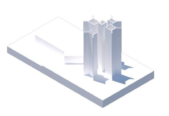
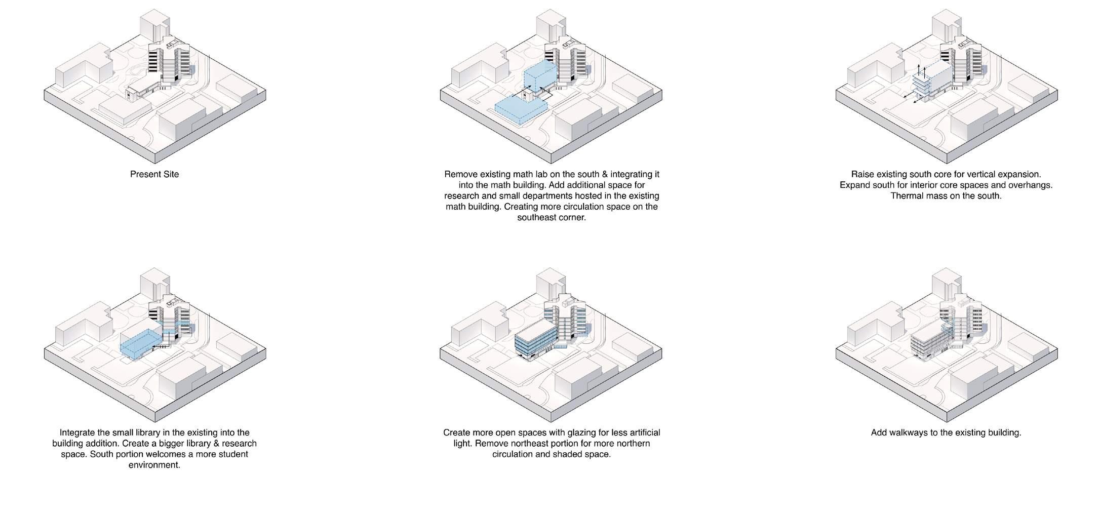
Extrude the core in the vertical direction for all floors.
Identify the building footprint & topography close to the old math department originally in the physics building on the northwest (PAS).
of the a tree. airs.
Extrude the core in the vertical direction for all floors.
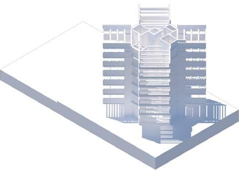
Concrete beams span across all sides and show on the exterior. These act as the “branches”. Cantilever out similar to a tree as well.
and add vertical circulation for it.
Place massing on raised side of land and center of 2 axis intersection
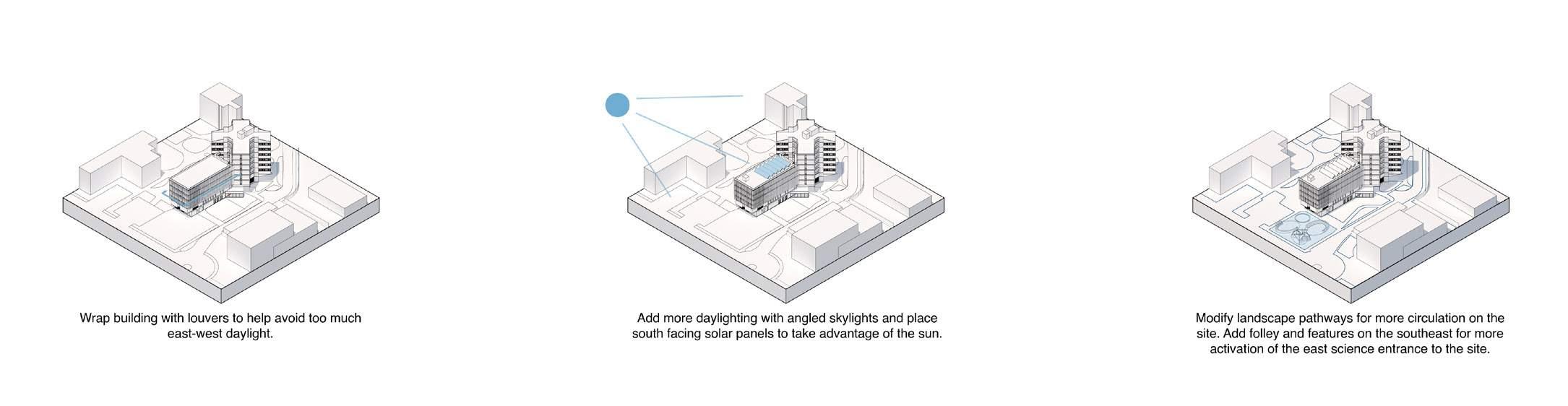
Add louvers on the windows of the building. These are essentially the “leaves”. Add openings for the core areas as well for sunlight and energy conservation. (Present building) roads.
Funnel in students coming from the paths & roads from all directions of the campus. Utilize topography on southern side by lower ing onto the less elevated area. Orient highly active sides on the north
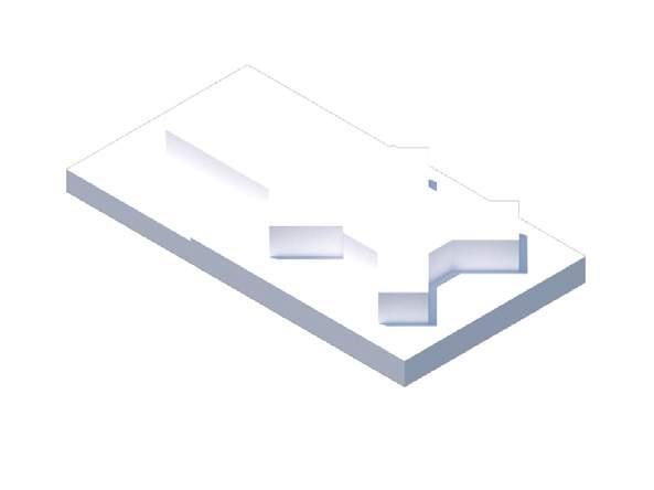
Cut open northwest direction to welcome students into the department from the phys ics building
Concrete beams span across all sides and show on the exterior. These act as the “branches”. Cantilever out similar to a tree as well.
Create another floor on the southern side and add vertical circulation for it.
Add louvers on the windows of the building. These are essentially the “leaves”. Add openings for the core areas as well for sunlight and energy conservation. (Present building)
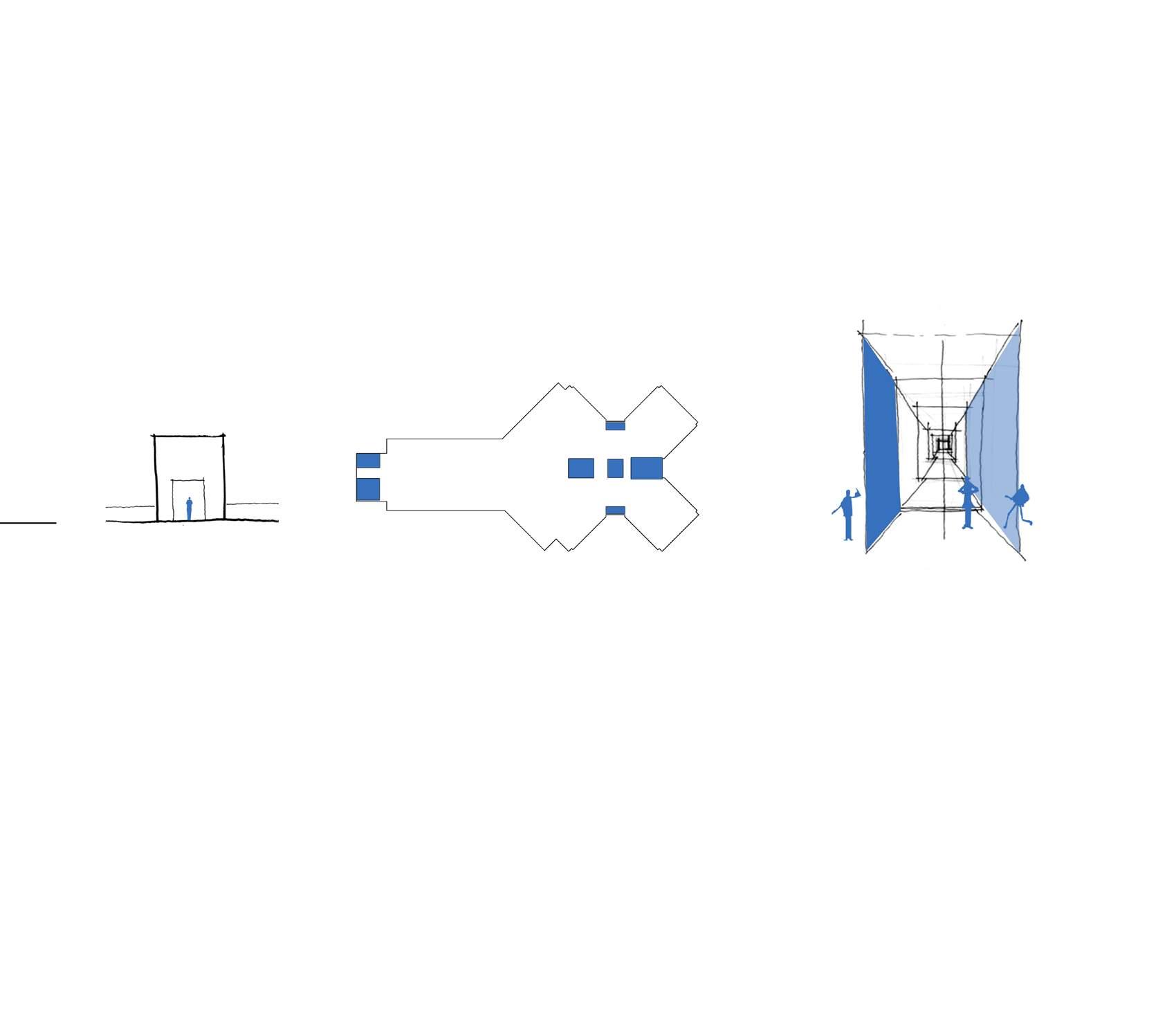
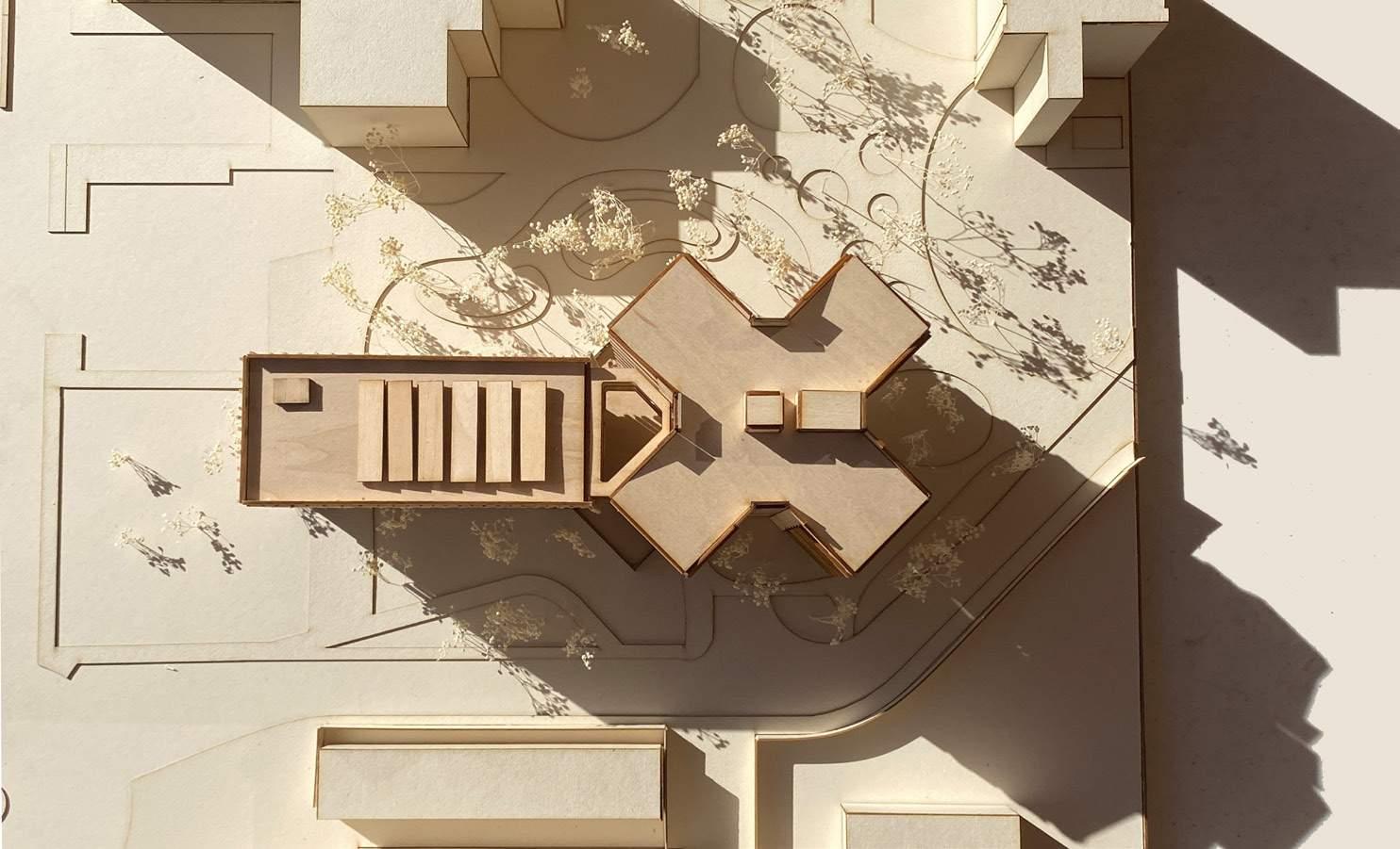
CONCEPT OF THE BUILDING
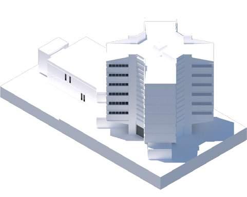
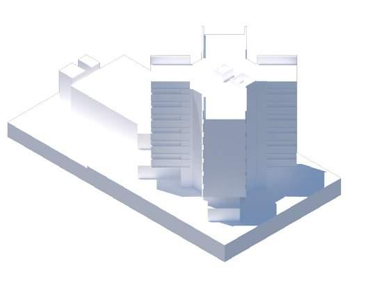
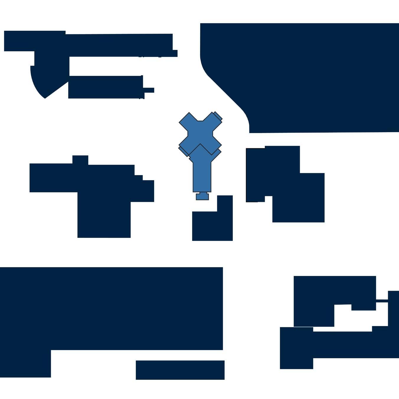
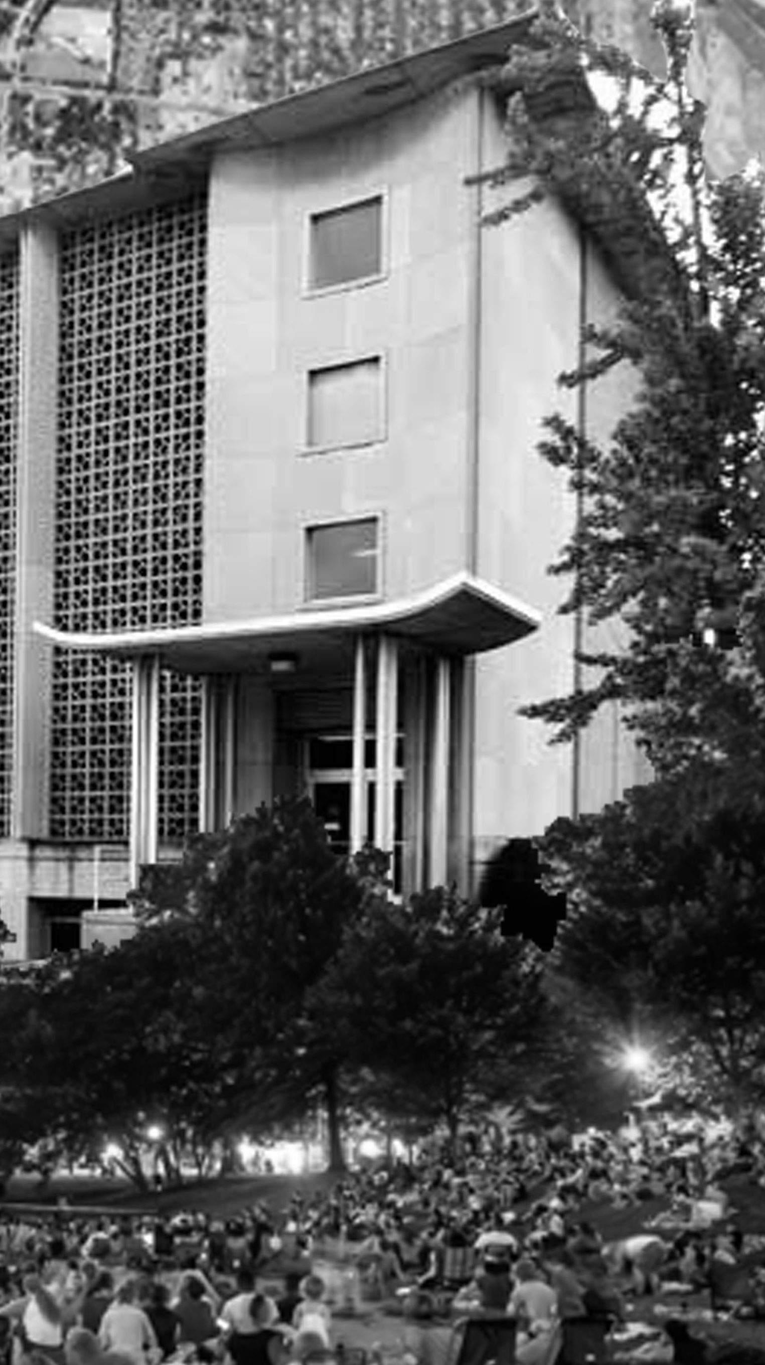
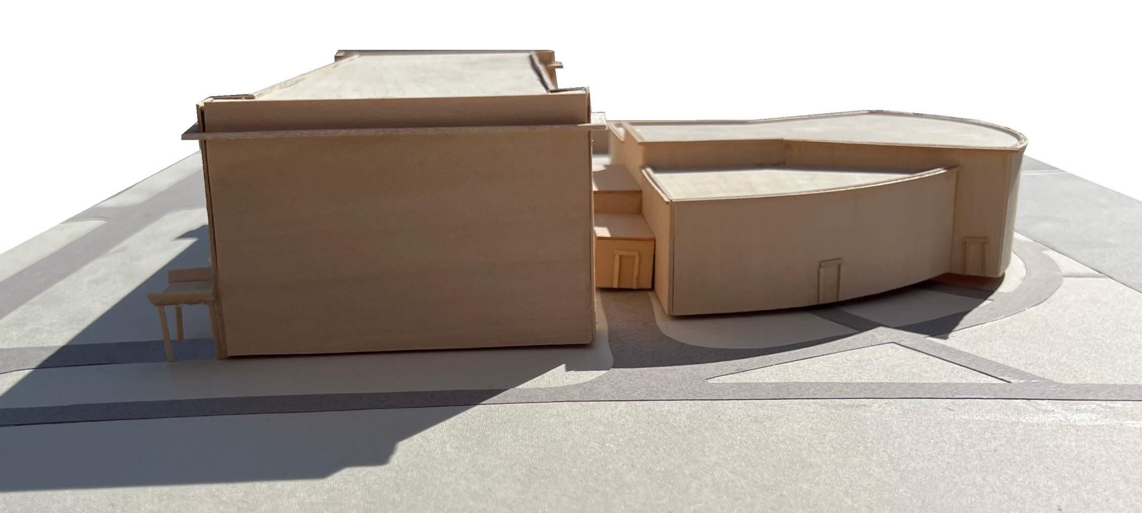
The concept of the building by Cain Nelson & Ware was thought to be building as the tree and the X part as the branches of the tree. In the
building the cores form the trunk of the tree and the X part which turns into floors seems to be as the branches of that tree. The cores are
consolidated in one chunk making the services core very clear throughout the building.
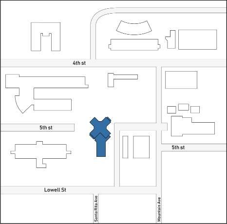
The building is surrounded by other buildings very closer to it giving very compact space in terms of circulation and openness.
The setbacks as per current standards are studied and marked in the diagram which gives very less room of expansion around the building.
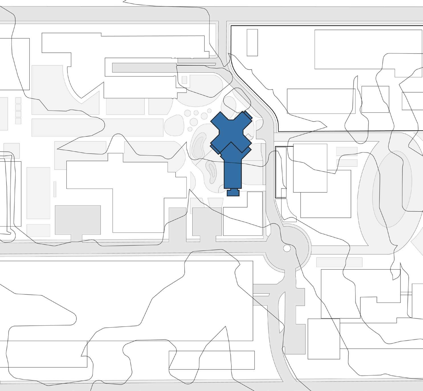
The topographic map suggests that contours on the south are low and with 2 ft intervals they are gradually ascending towards the north east of the site. The slope is not that steep and barely felt on the site.
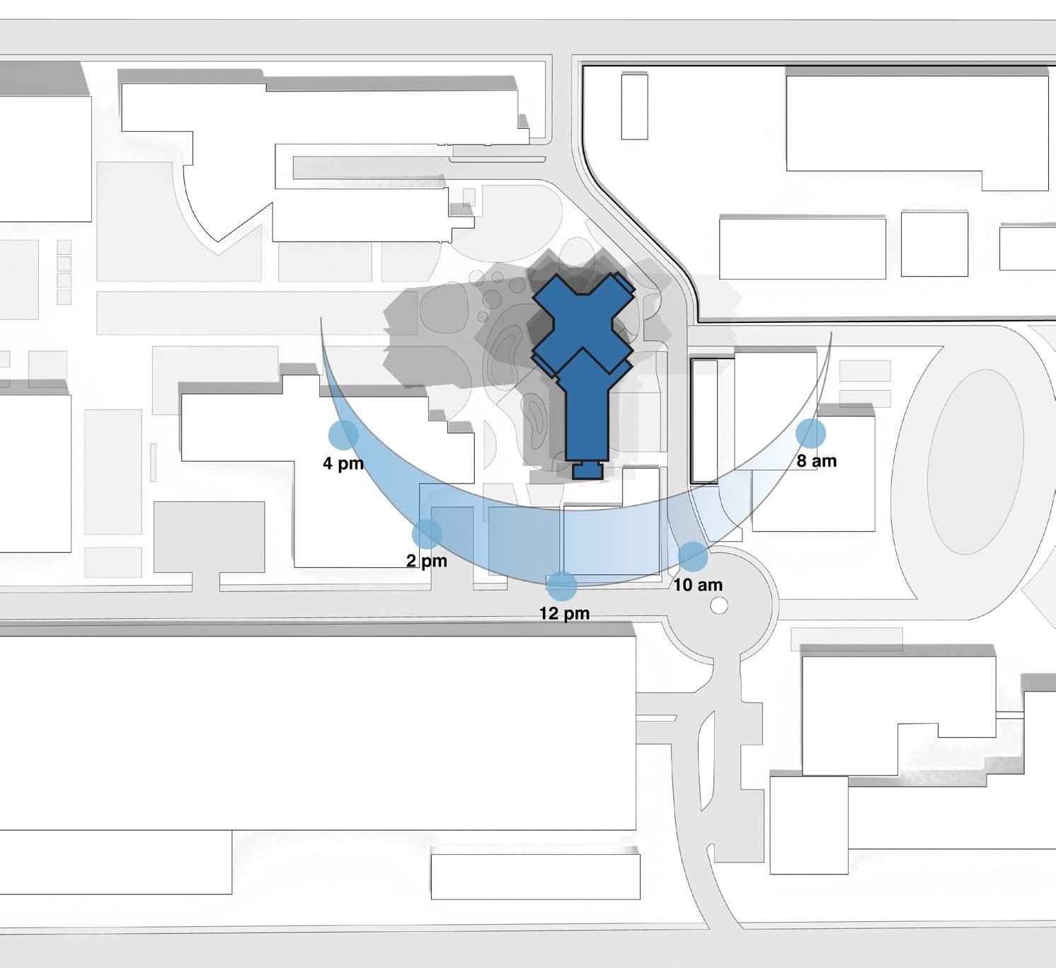
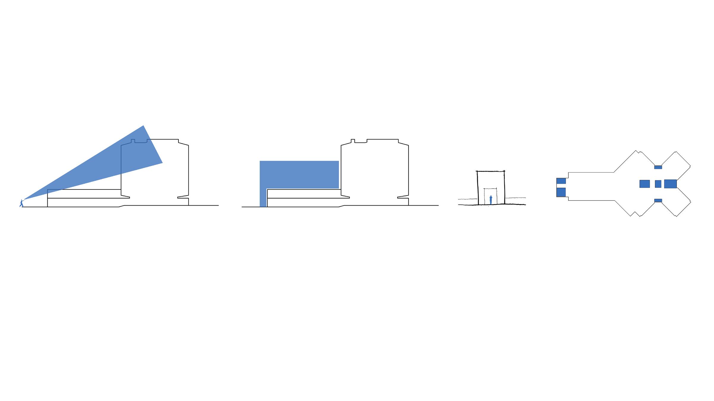
The current orientation suggest that lower mass on the south and major mass on the north. It cast shadows which keep the X part shaded almost throughout the day where the openings are present.
In response to the hot air from thee Sonoran desert there were multiple strategies used by the architect to respond to it but which turns out to
be blocking some natural lighting to the building. Some of these strategies included use of small openings like lattices from the brick. Also the
structure becomes visible on the outside giving it a character of the brutal architecture style.
Math Lab
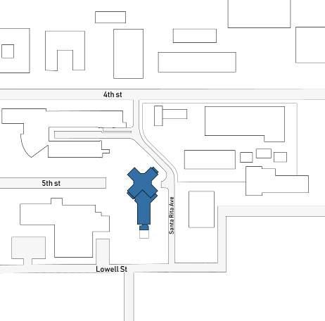
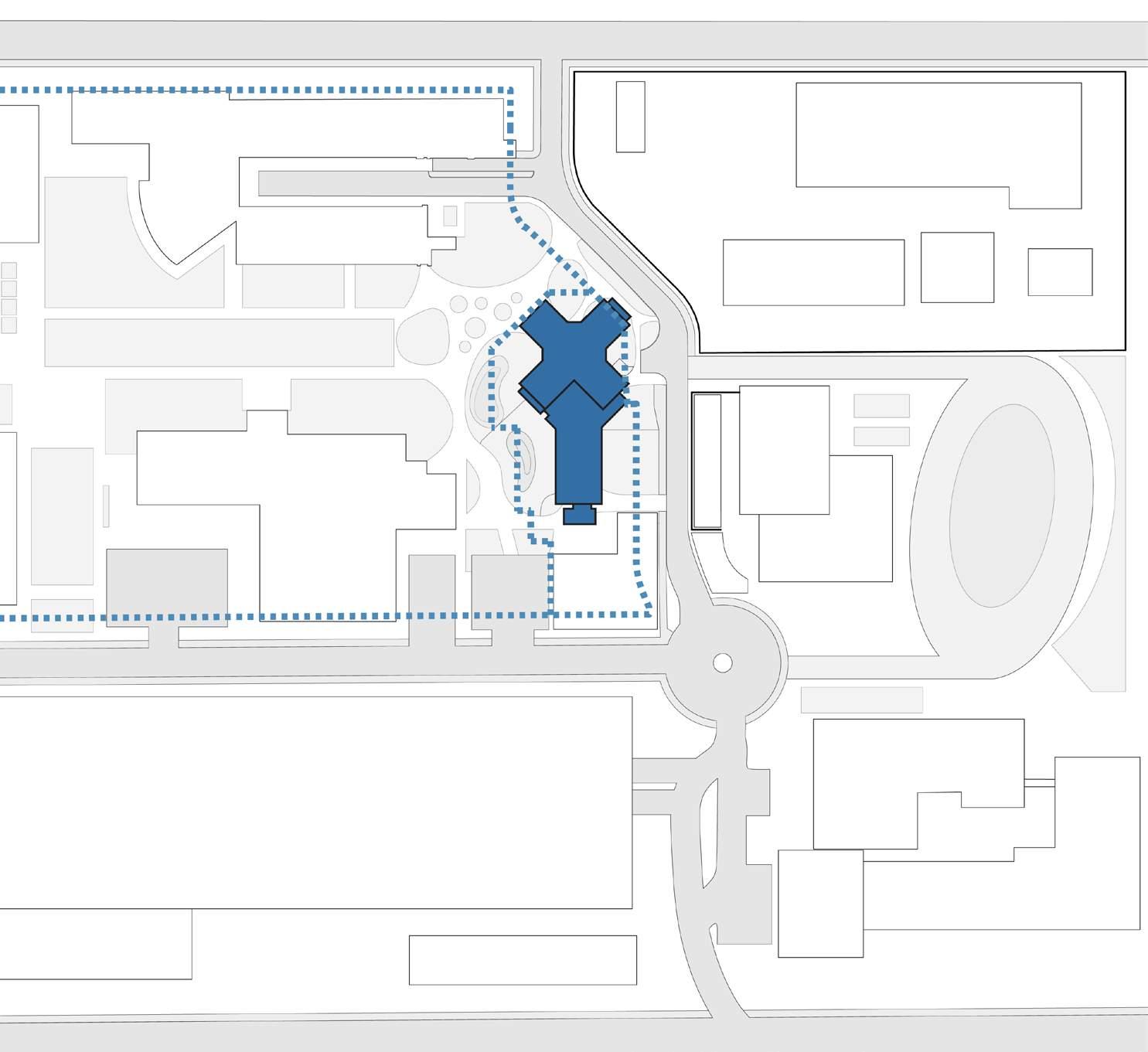
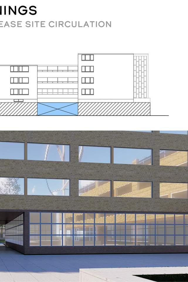
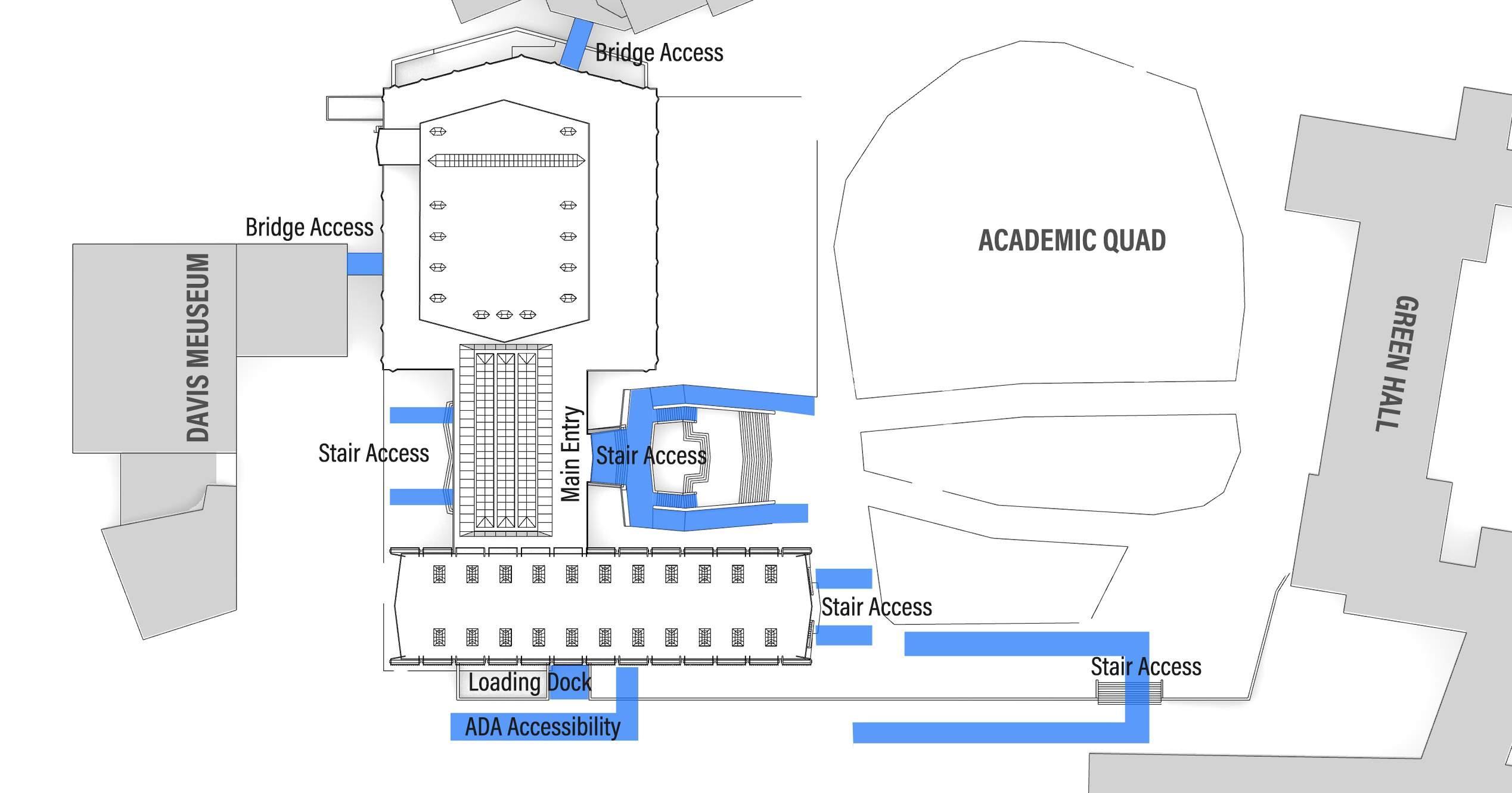
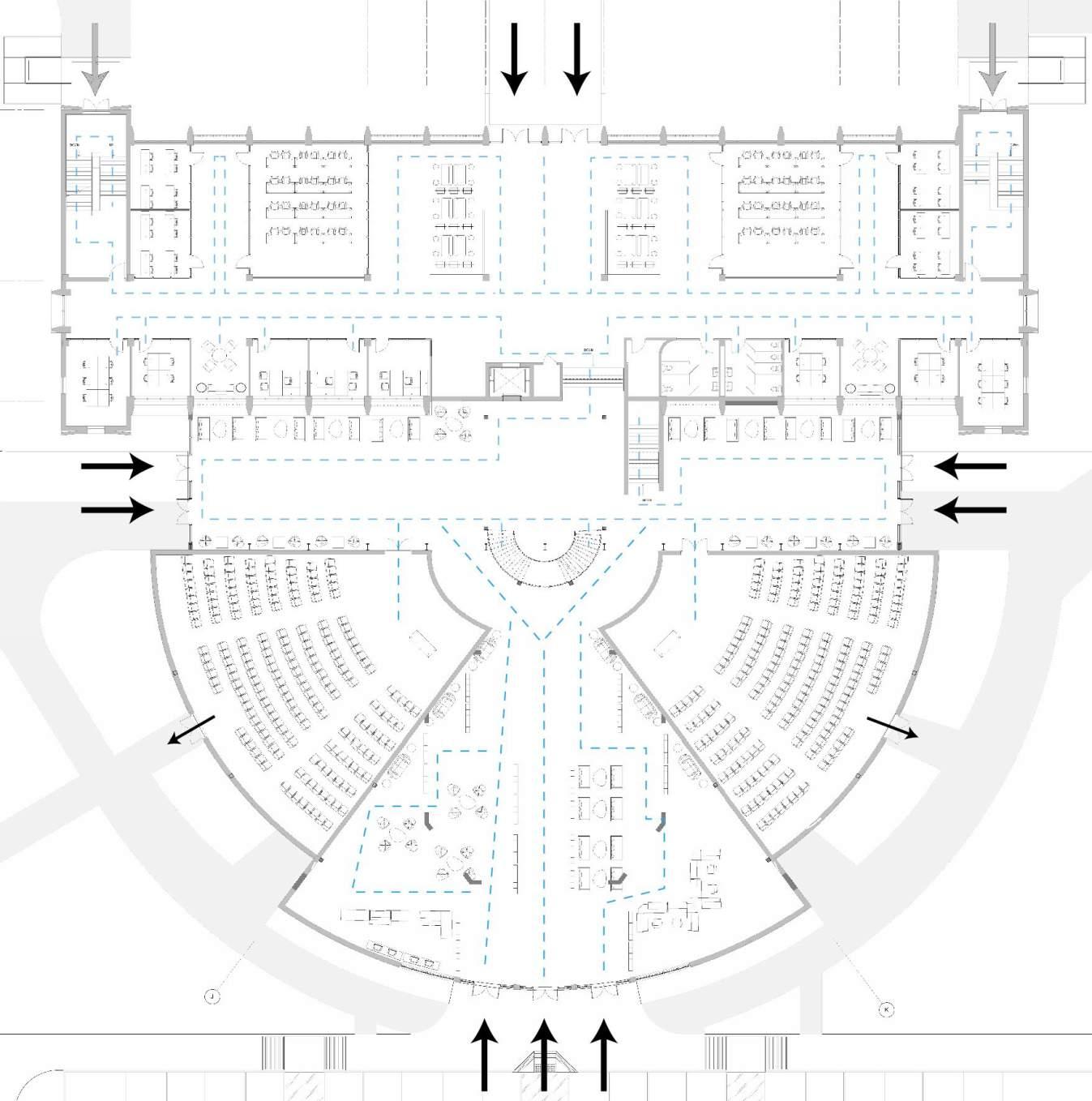
The above map shows the existing circulation and the blockage by the math lab at the main drop-off point on the campus. The major circulation
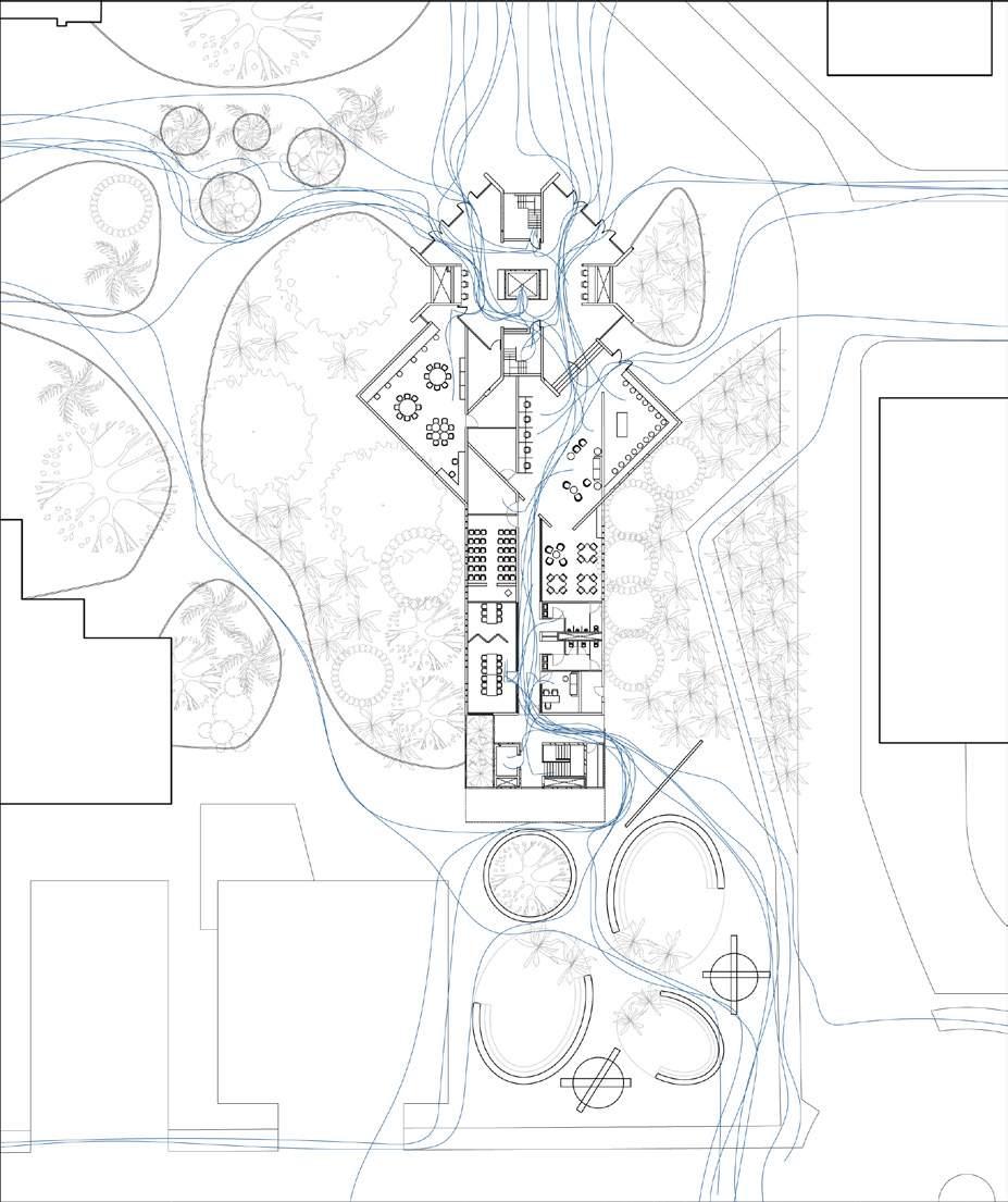
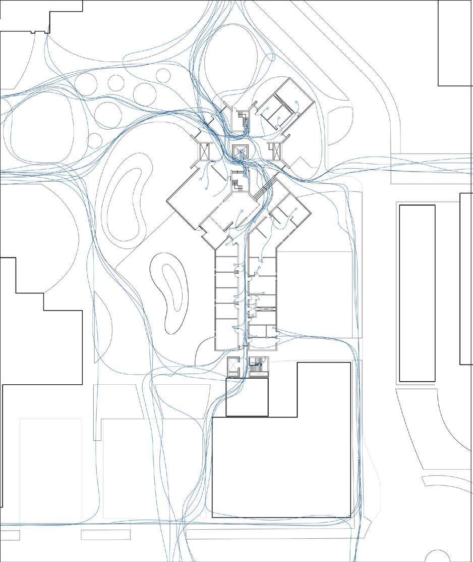
occurs on the North , South and West due to connectivity with the transit systems and the parking. While on the other hand the proposed circulation
tries to be more fluid and creating the pause points near the drop-off points.
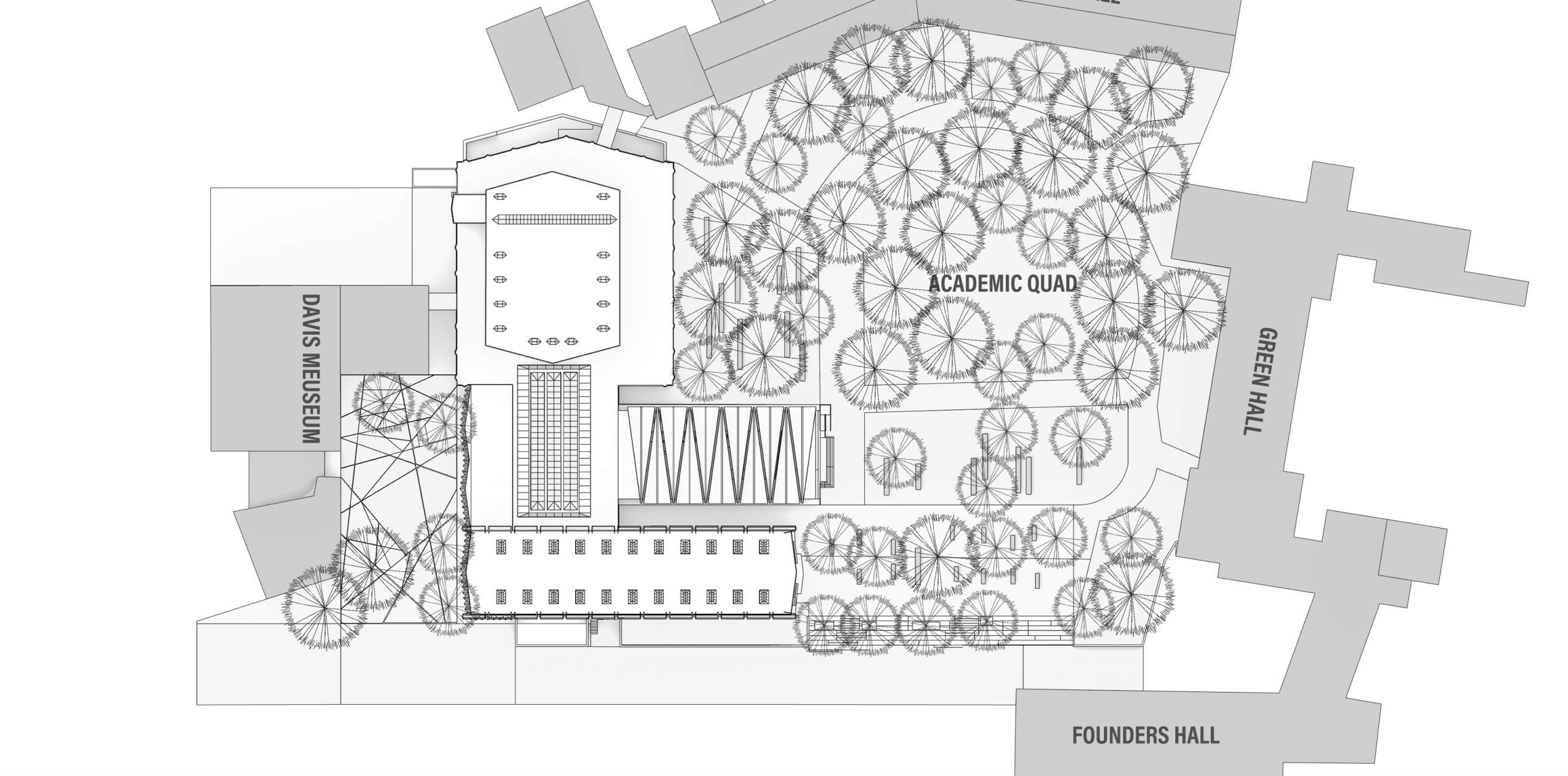
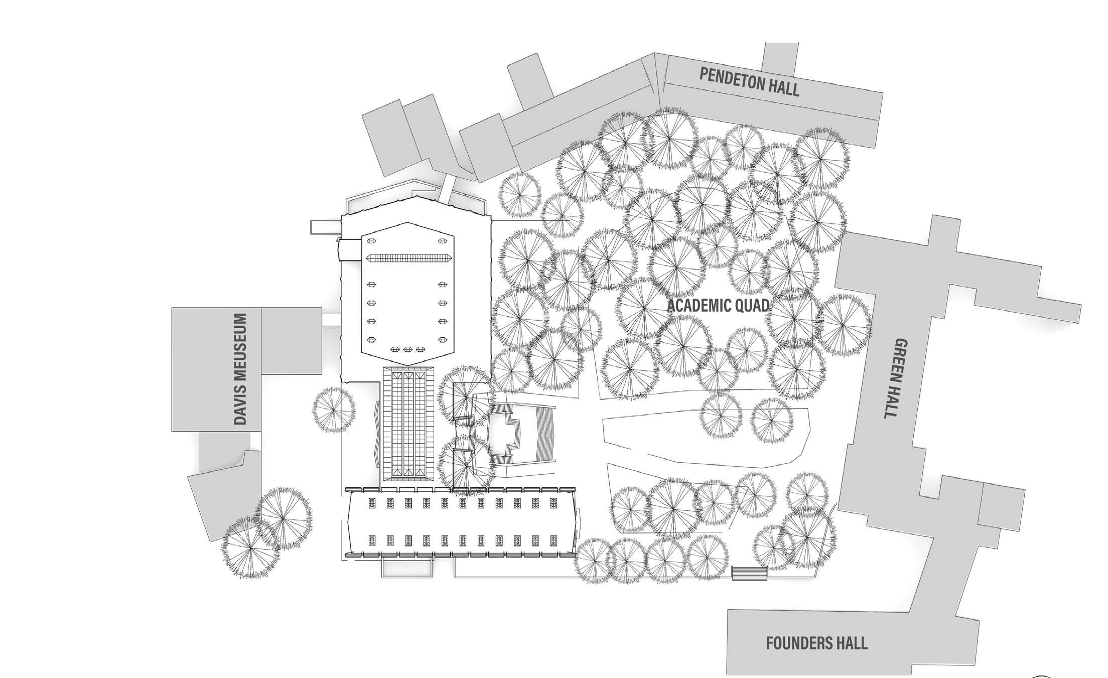
The campus was designed with the greenbelts flowing horizontally on the site. The larger one being near the old main and other smaller dense part
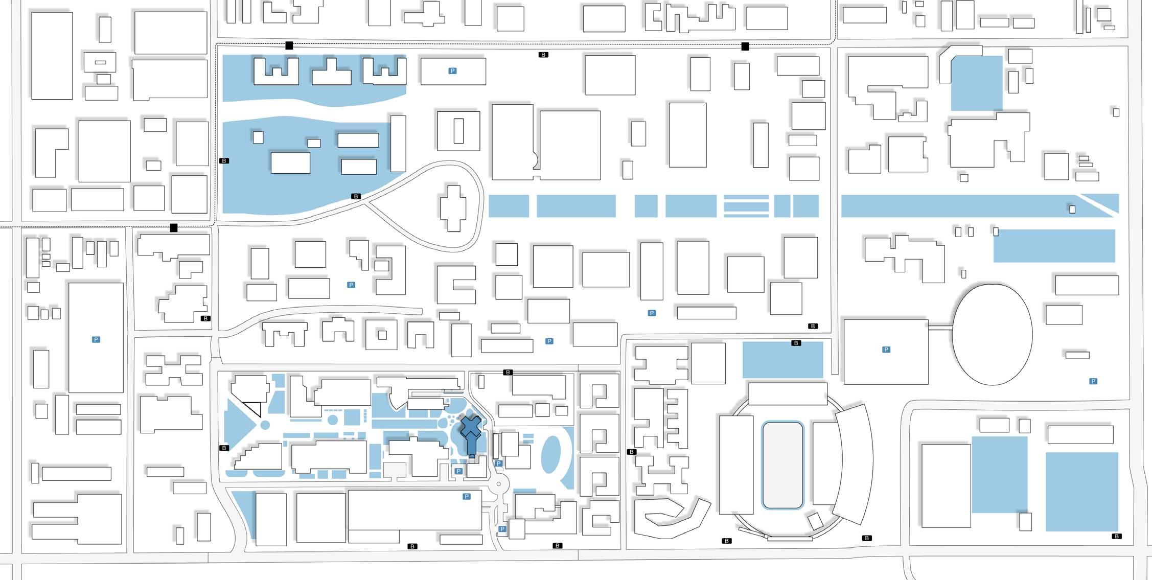
falling on the science core. It forms a connectivity through the greens from west to east. This map helps us to visualize the greater greens occurring
on the site and connection of that with the math building.
As seen in the map the greens surround the science core as well as it forms a strong visual axis from the west of the math building. There is
lot of green in the entrance and the west and east side of the building. It helps in creating a blockage from the hard sun rays during the daytime from
both the directions. It was strategically planned by the architect.

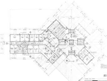
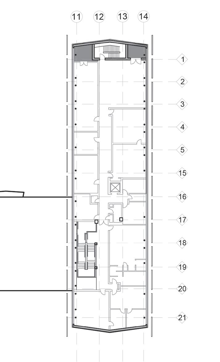
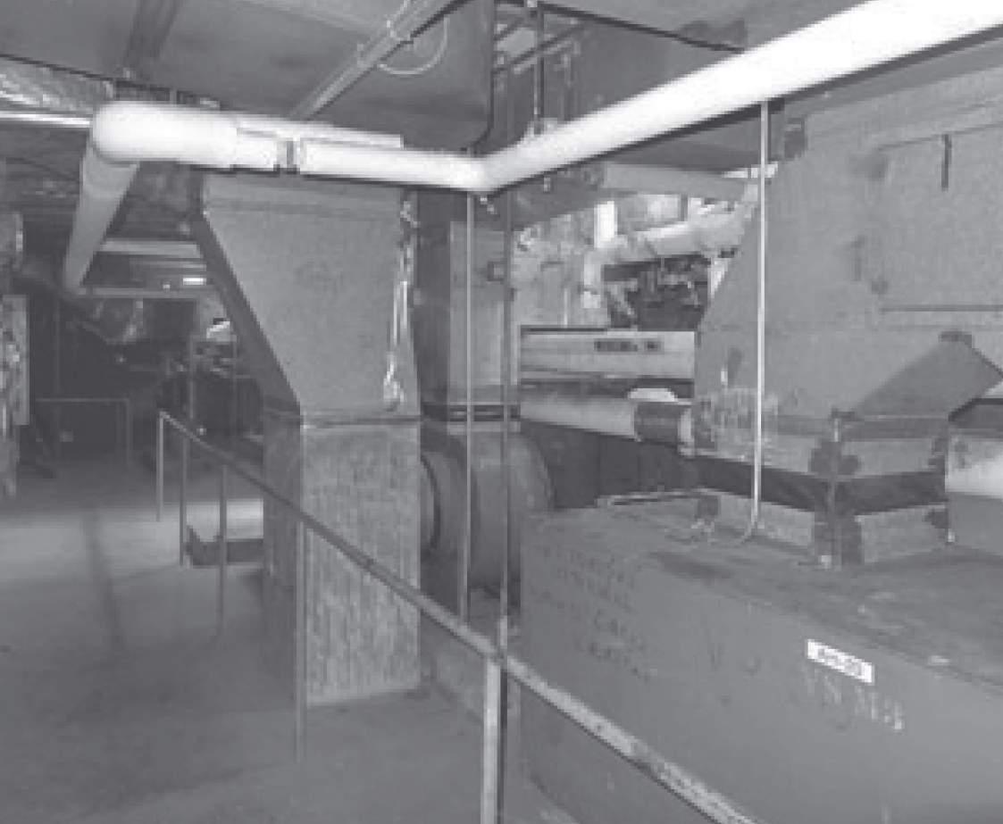
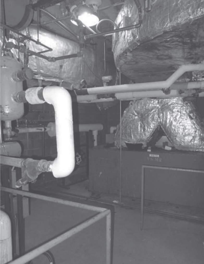
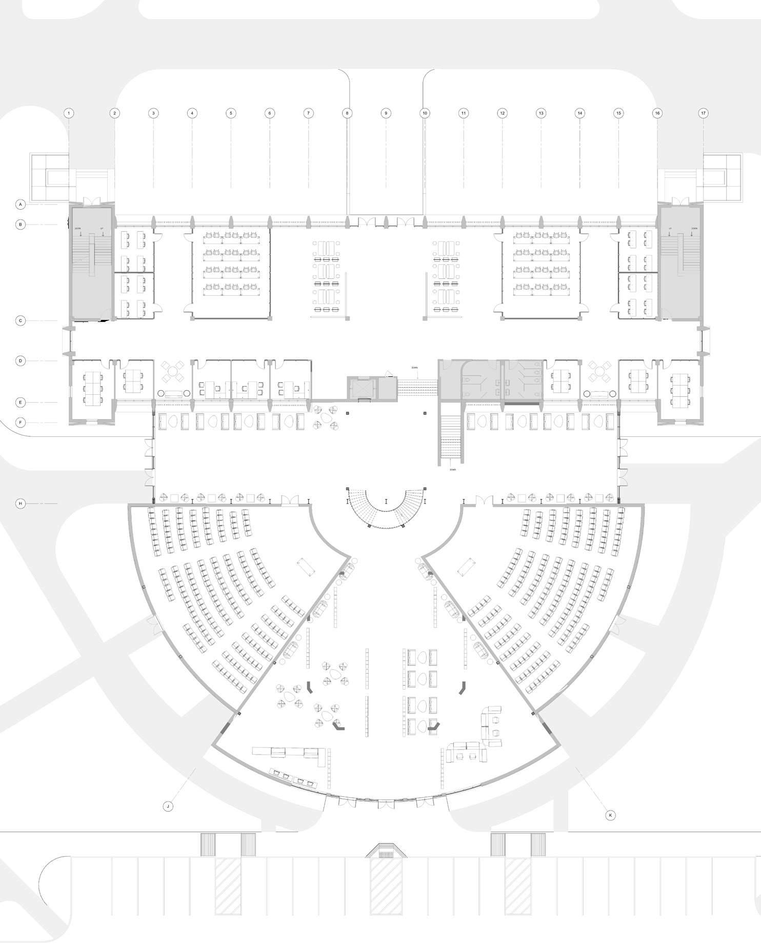
basement comprises of mostly mechanical and technical program in it with the service tunnel running in it.
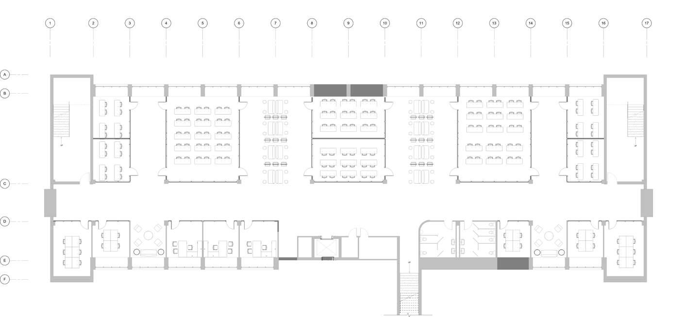
1. Office 2.Seminar Room 3. Department Head room 4. Corridor 5. Lobby 6. Janitor Room 7. Male Washroom 8. Duct Shaft 9. Staircase 10. Elevator 11. Individual Study room 12. Studio 13. Control Room
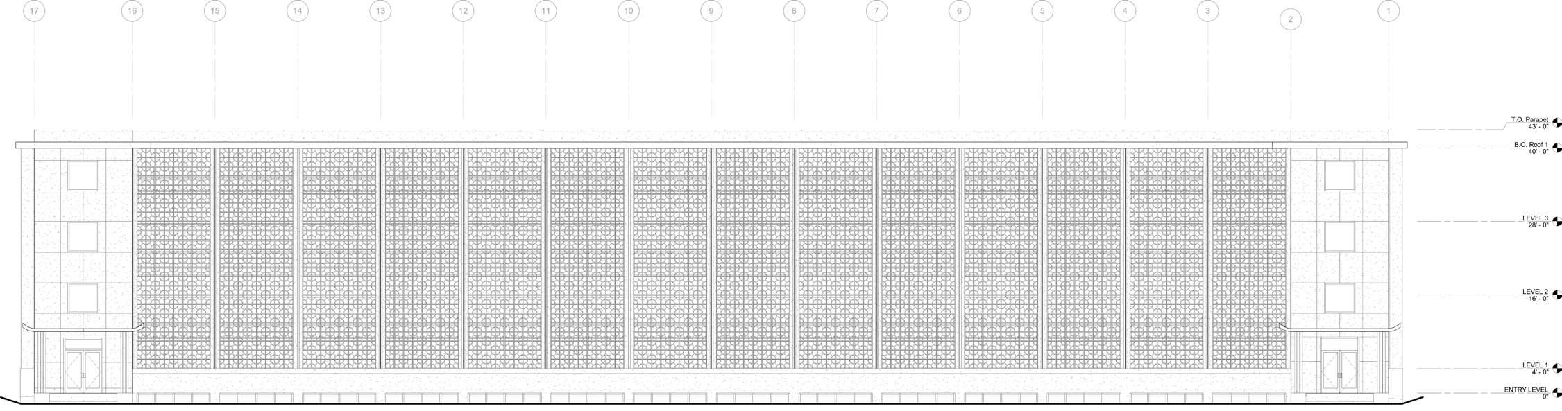
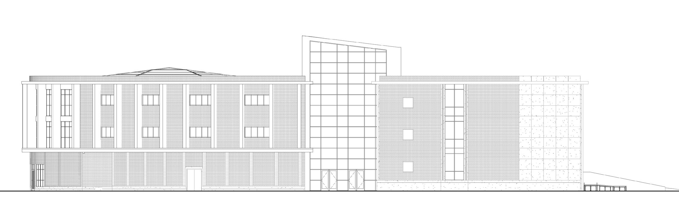
as the concrete band exposing the structure on the outside. The openings are very thin.
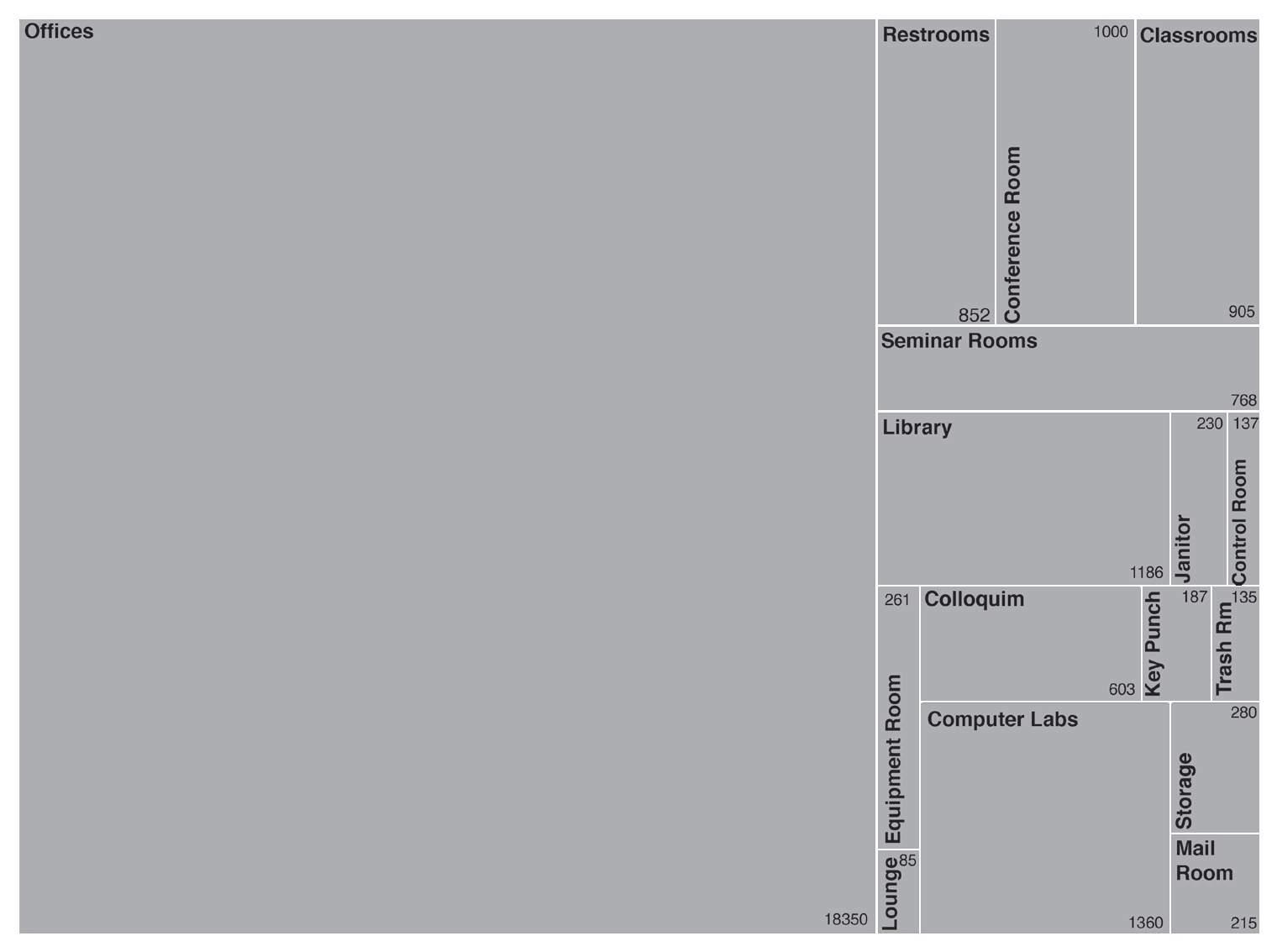
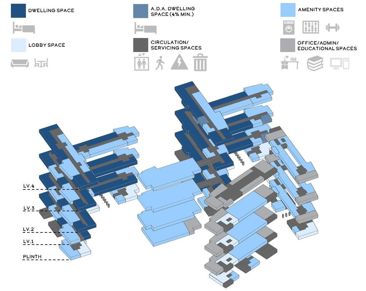
The existing program includes a lot of offices and with very less classrooms and the library spaces. The major part is occupied by the offices on the each floor scattered in varied directions throughout different floors.
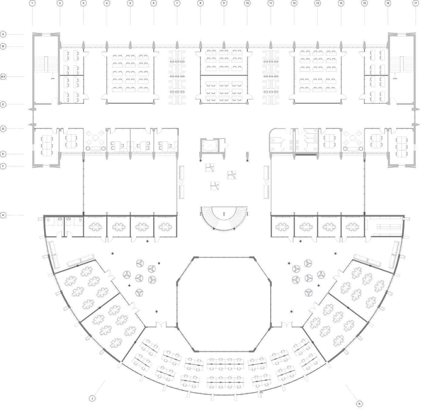
The newer program emphasis on the giving importance to student activities in the building and also the keeping the program of offices as it. The newer program also houses Math lab and library space which forms the key spaces in the expansion.
Community of science building around the maths building giving home to more collaborative and innovative multidisciplinary spaces
View impaired because of high wall for the plant
Visual greens never experienced due to opening positions
Contemporary new buildings in vicinity of the math building
Node Identity- Merging greens with the cul-de-sac and entrance to the building and forming important node for arrival
Easy access to parking areas
Easy access to parking areas
Community of science building around the maths building giving home to more collaborative and innovative multidisciplinary spaces
Forming the language of contemporary architecture due its location near 6th street
Maintaining the opacity for various activities and spaces


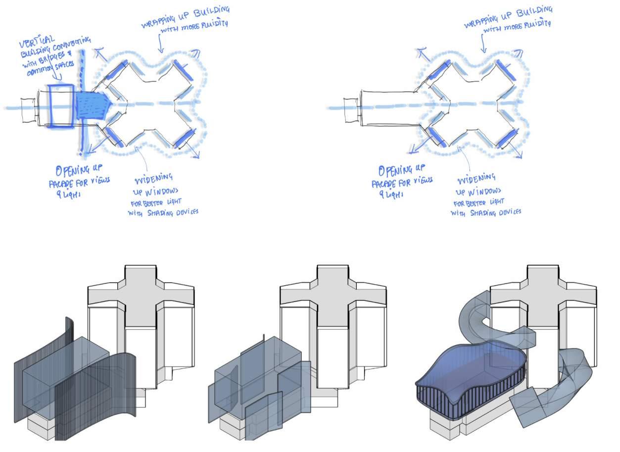
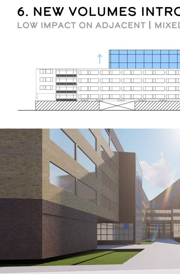
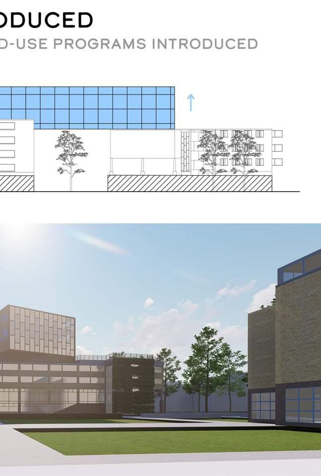
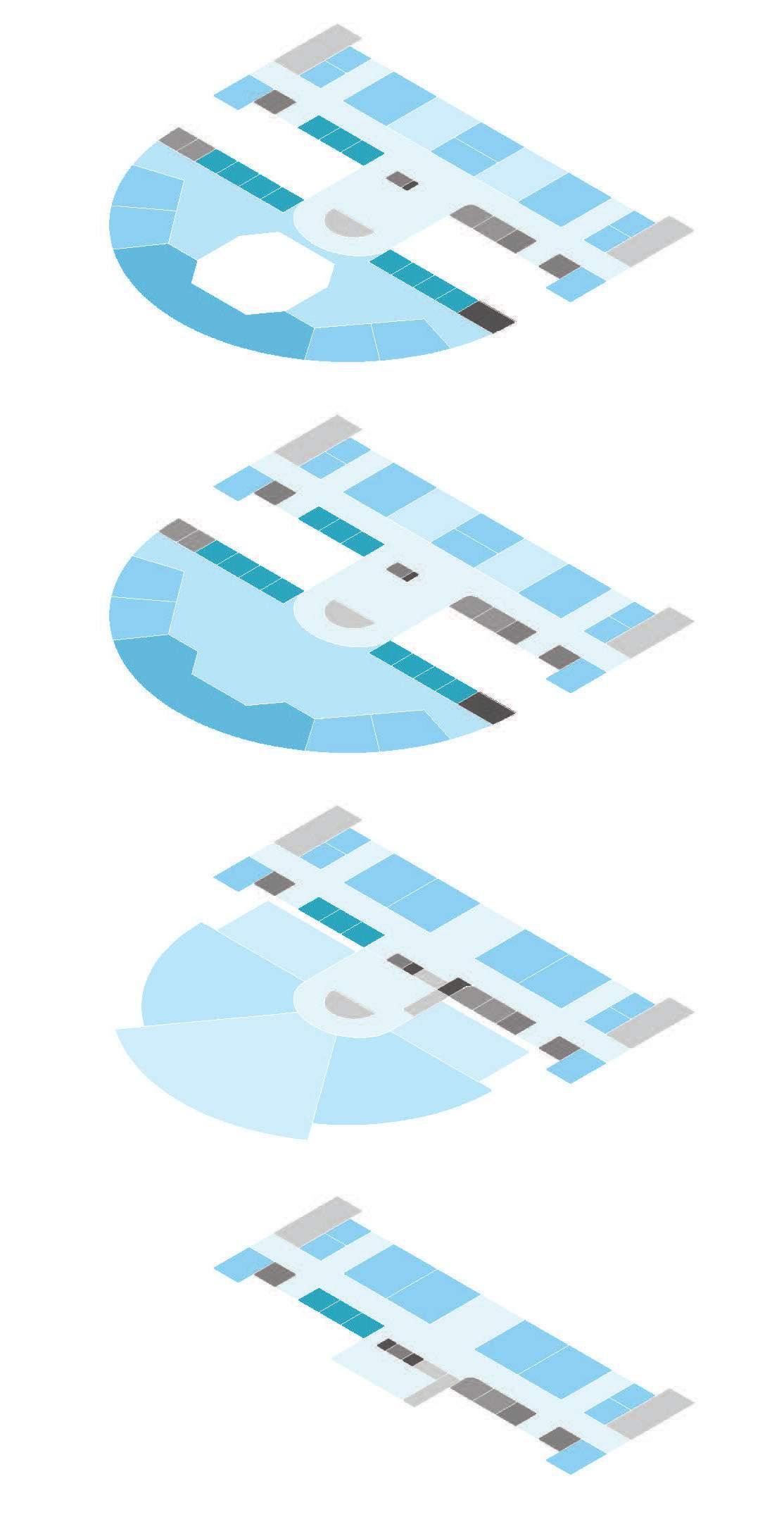
Given the site conditions the opportunities for expansion of the buildings are stacking, wrapping, and juxtaposition
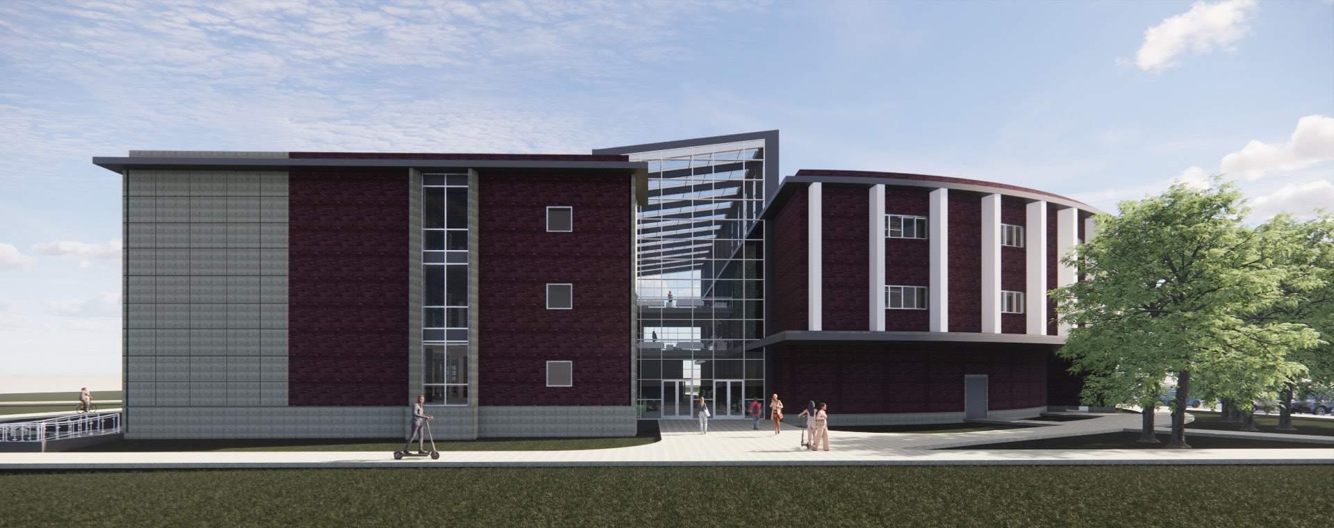
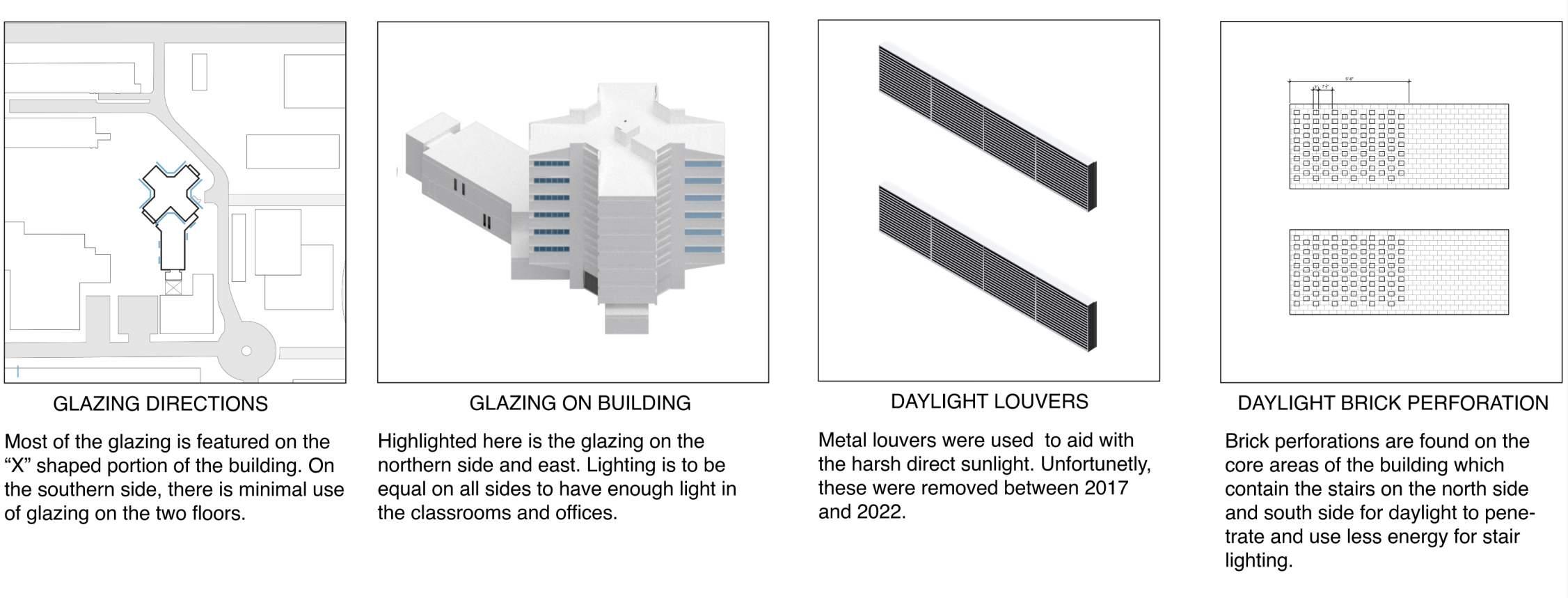
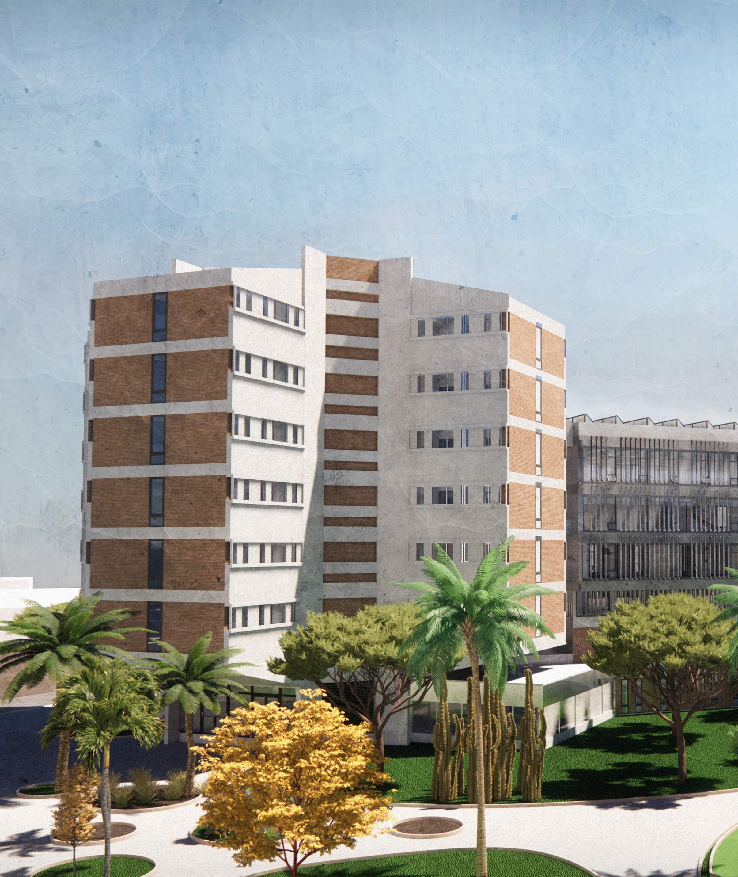
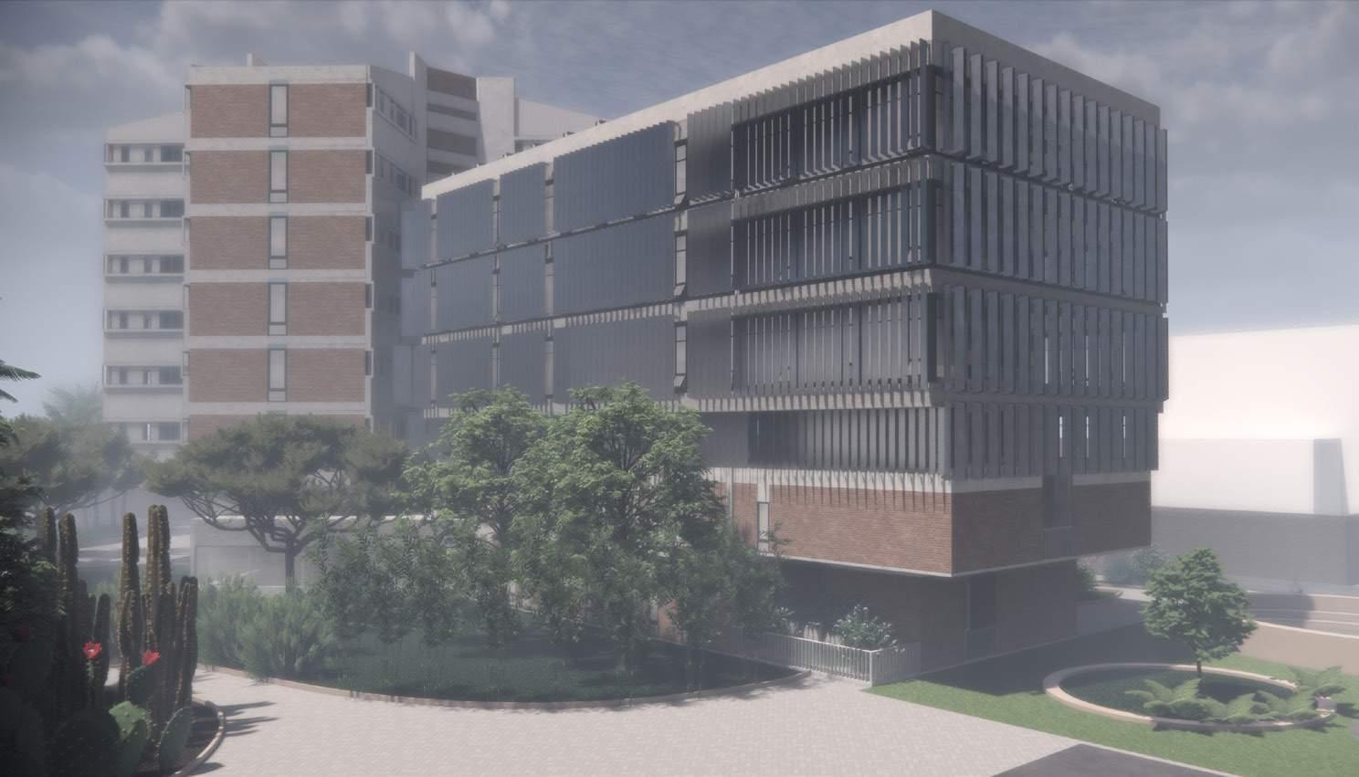
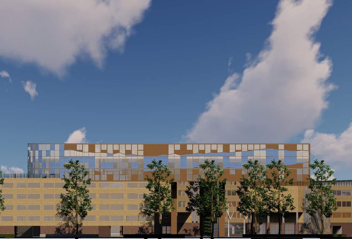
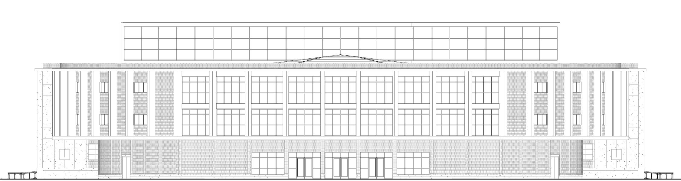
The design development focuses on responding to four directions to maximize the views, light and air inside the building. The materials
are chose according to the existing building typology in terms of only the color pallet. The design focuses more on transparency of the building and
connecting visibly throughout the campus.
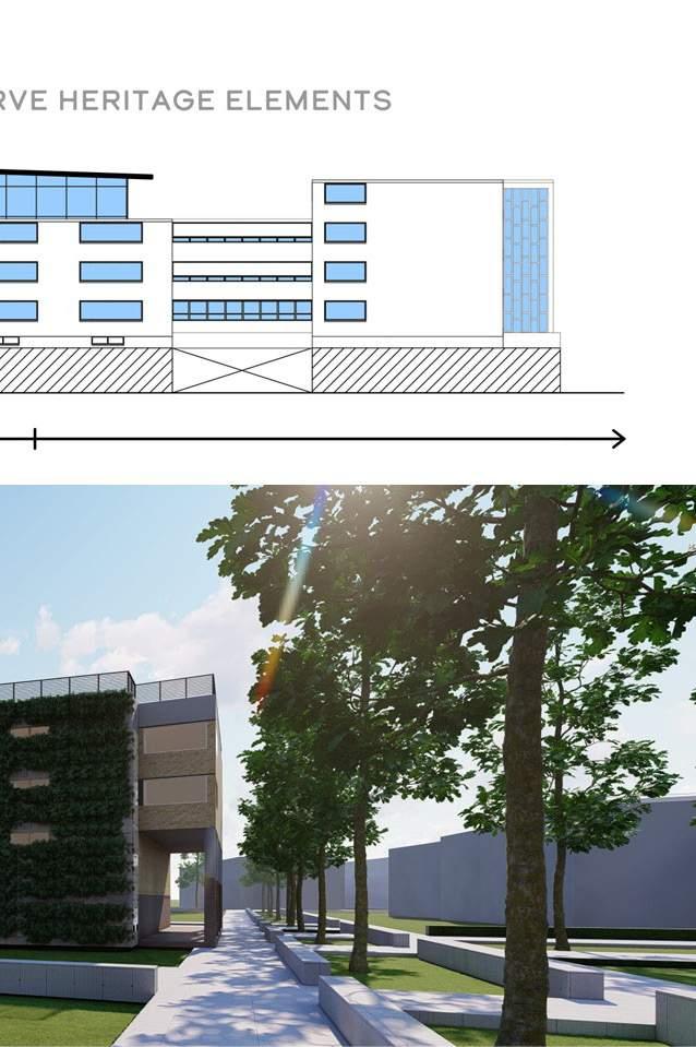
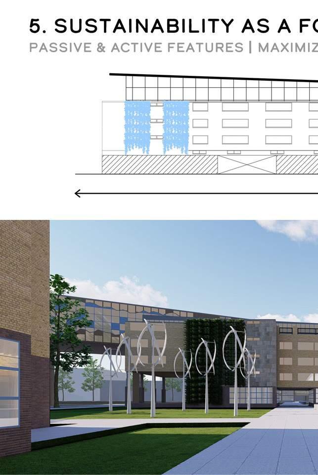
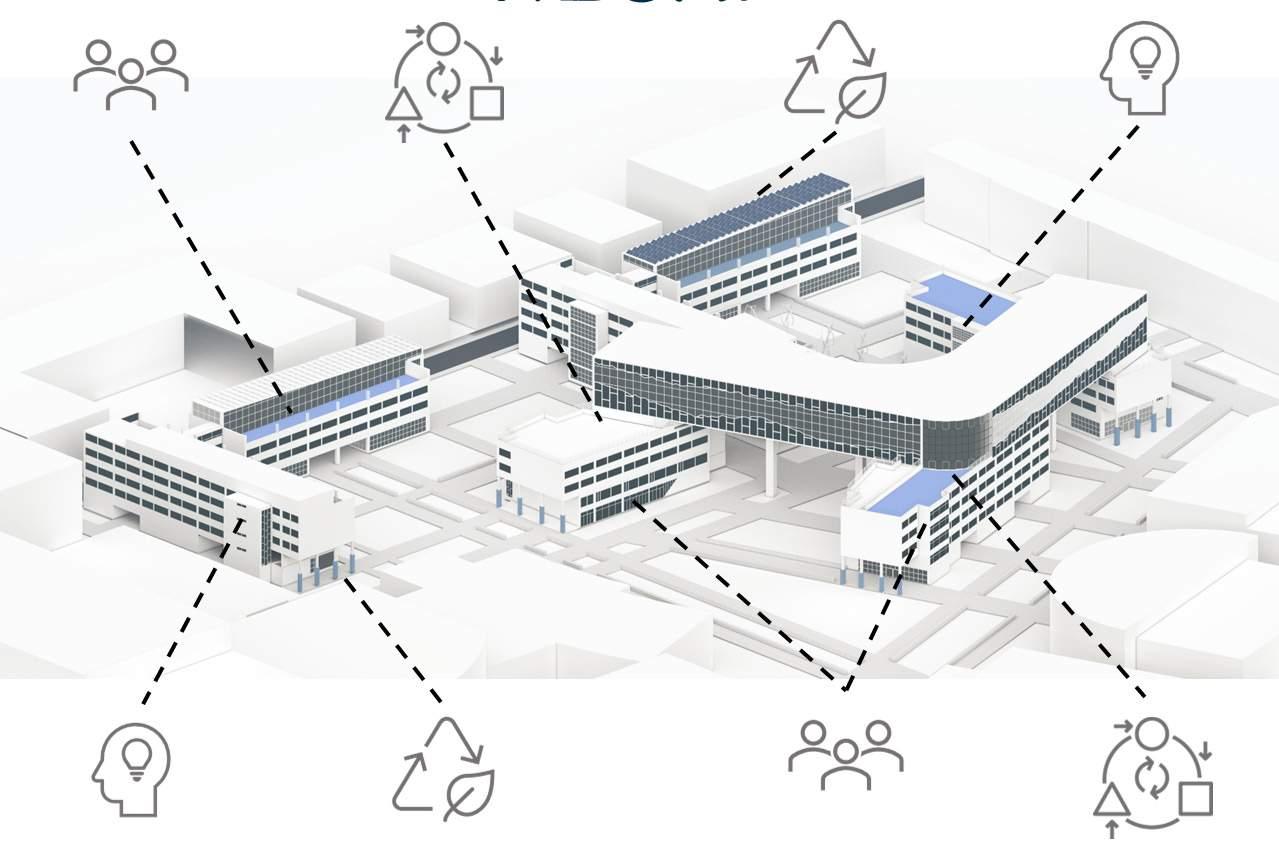
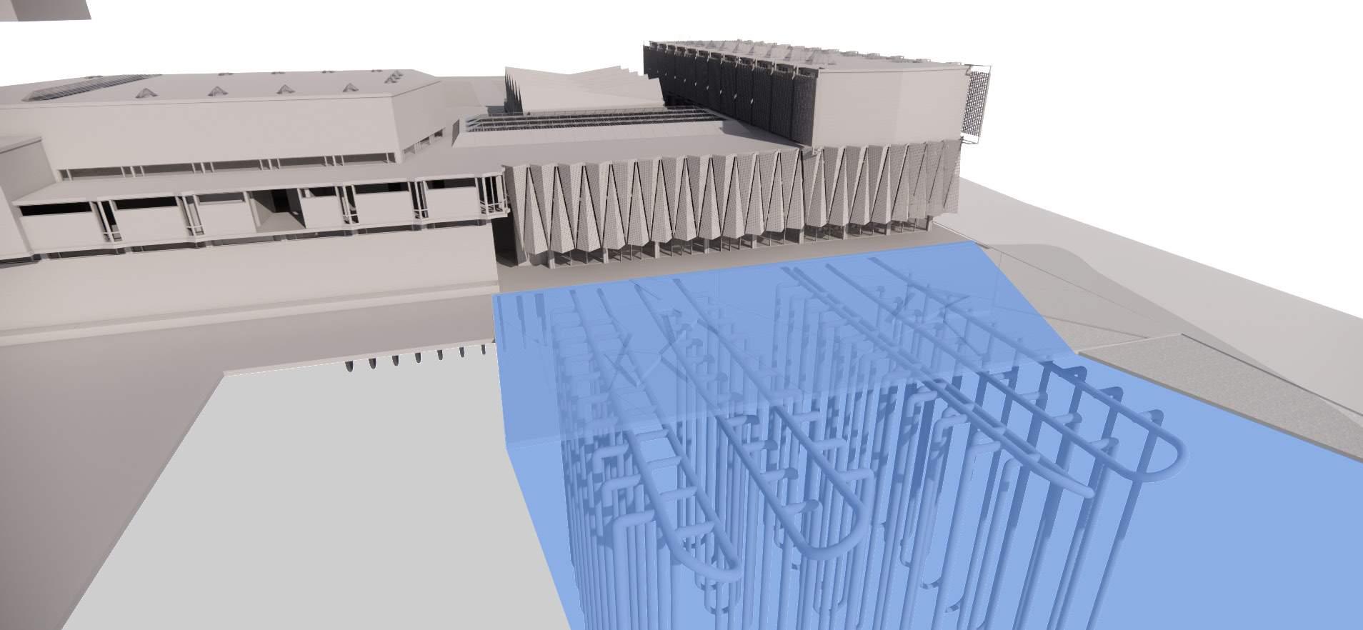
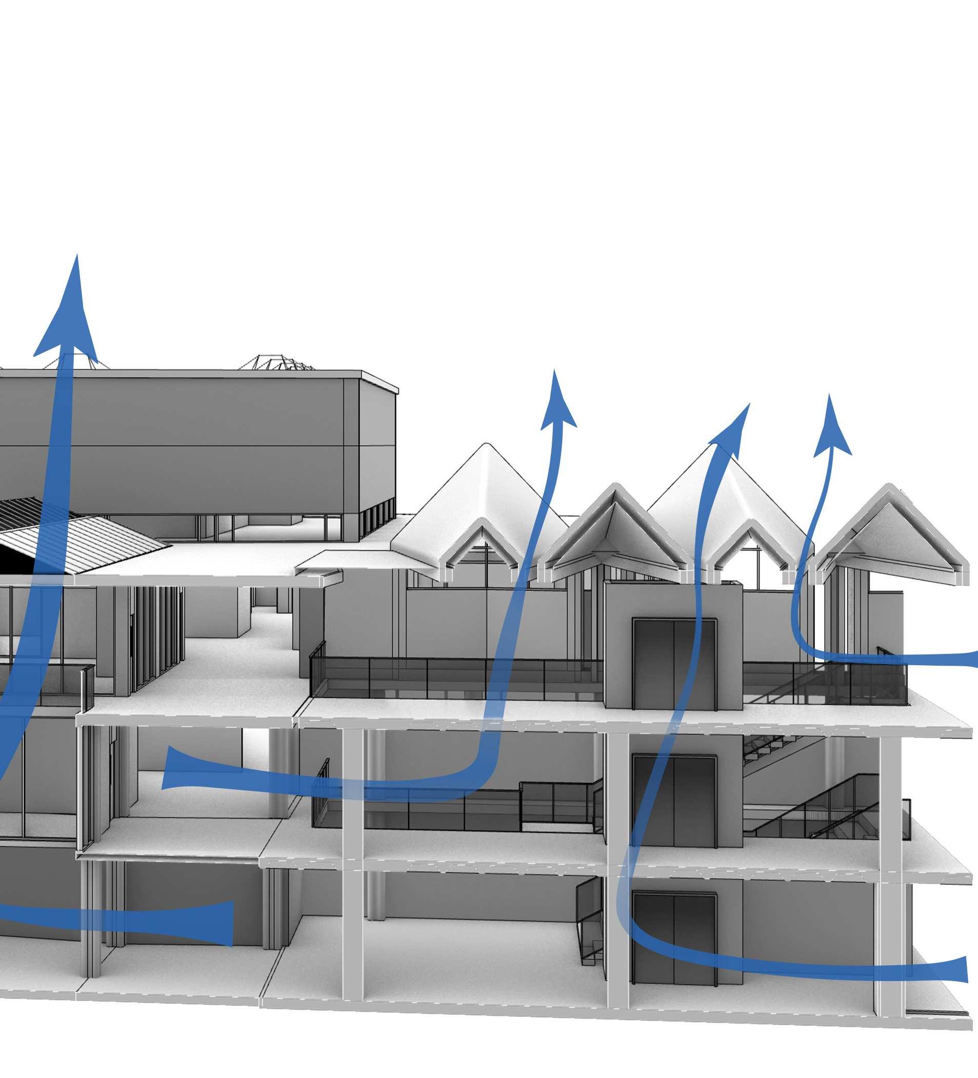
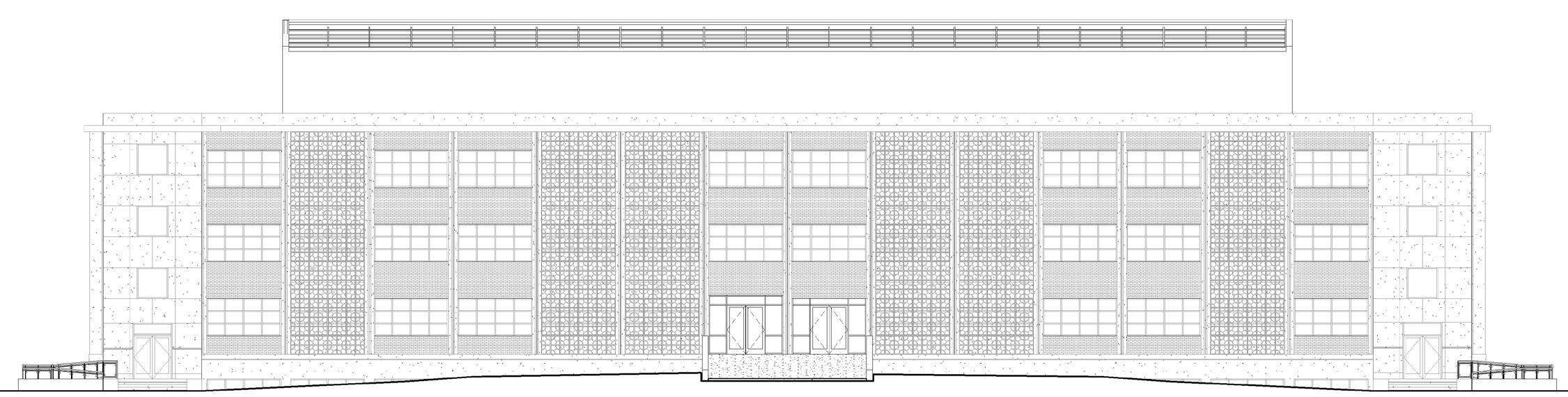
The strategies for the facade are worked according to the directions and studies are made according to the sun positions. The solar roof on
the top tries to capture the maximum south sun during the day and minimizing the direct heating of the roof. The green around it are layered
and are thought of shielding the ground and first floor from the harsh climate.
The design journey tested varied wrapping and stacking on the existing structure.
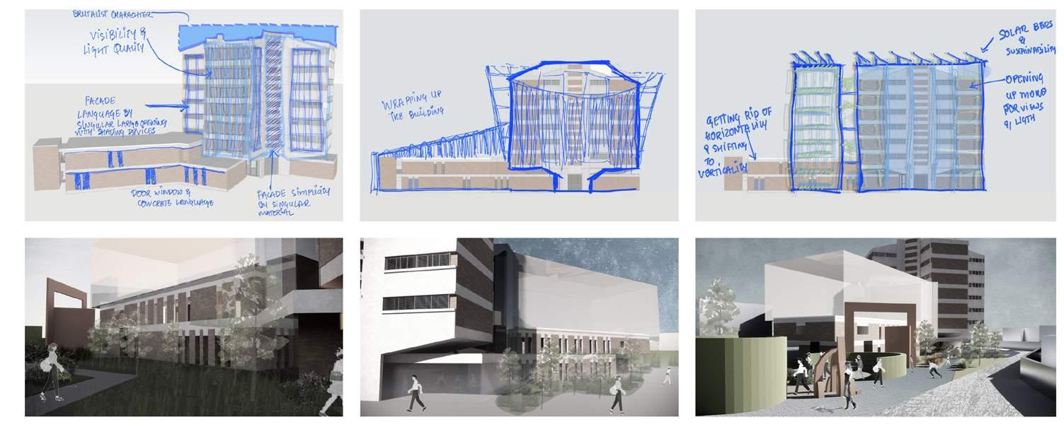
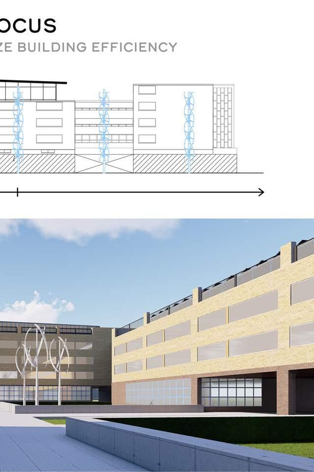
The sustainable strategies were worked on with the idea of covering the building and utilizing the solar resource at the maximum.
The facade studies were focused on the opening sizes, the transparency, the positioning of the flaps with respect to the angled building.
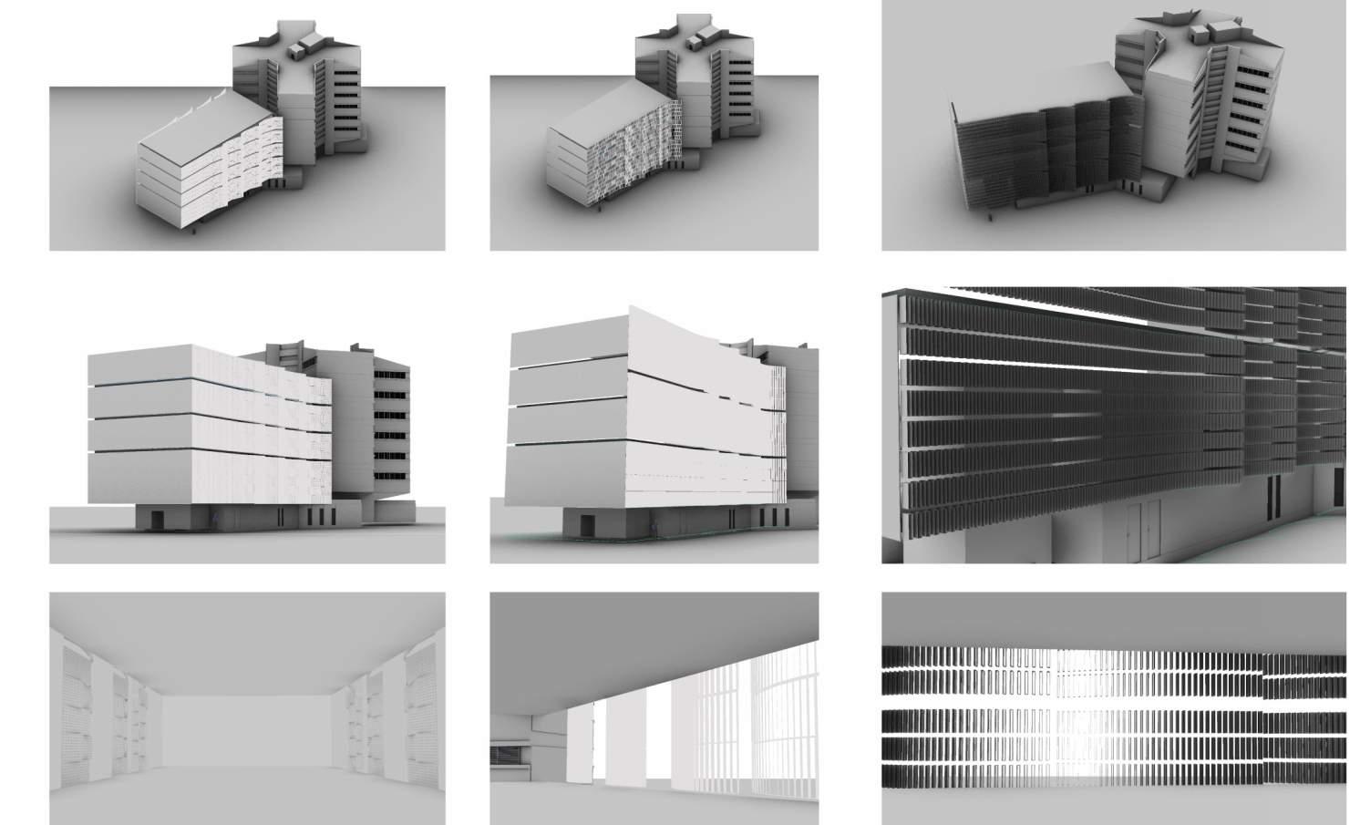
It shows the shadows casted during the sun position at 2 pm .
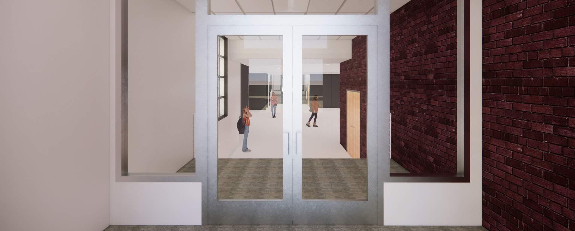
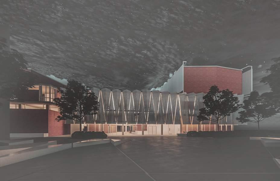
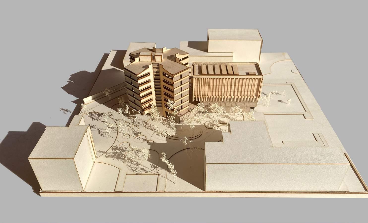
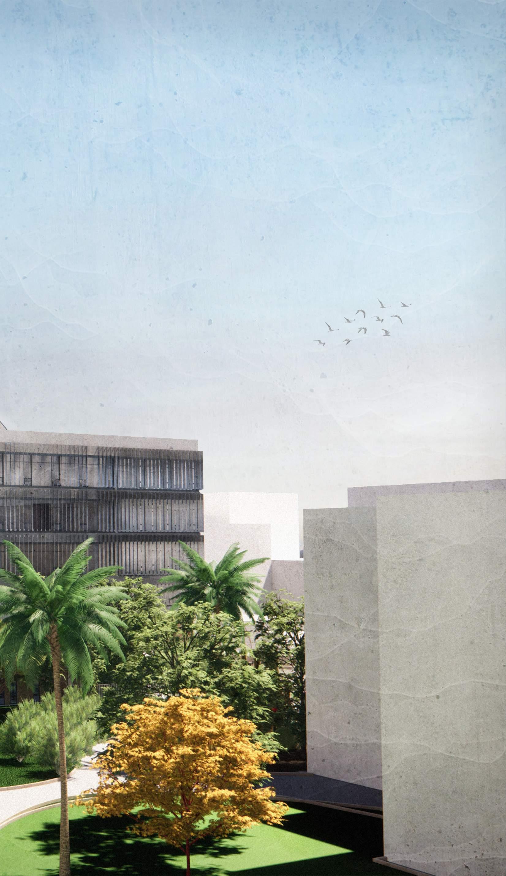
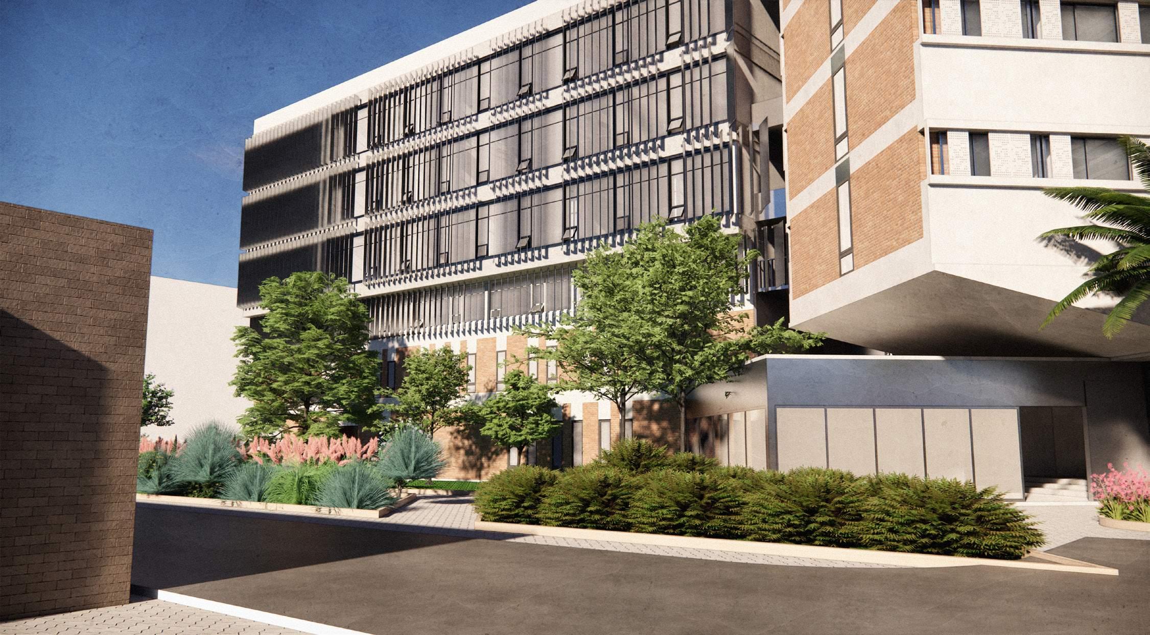
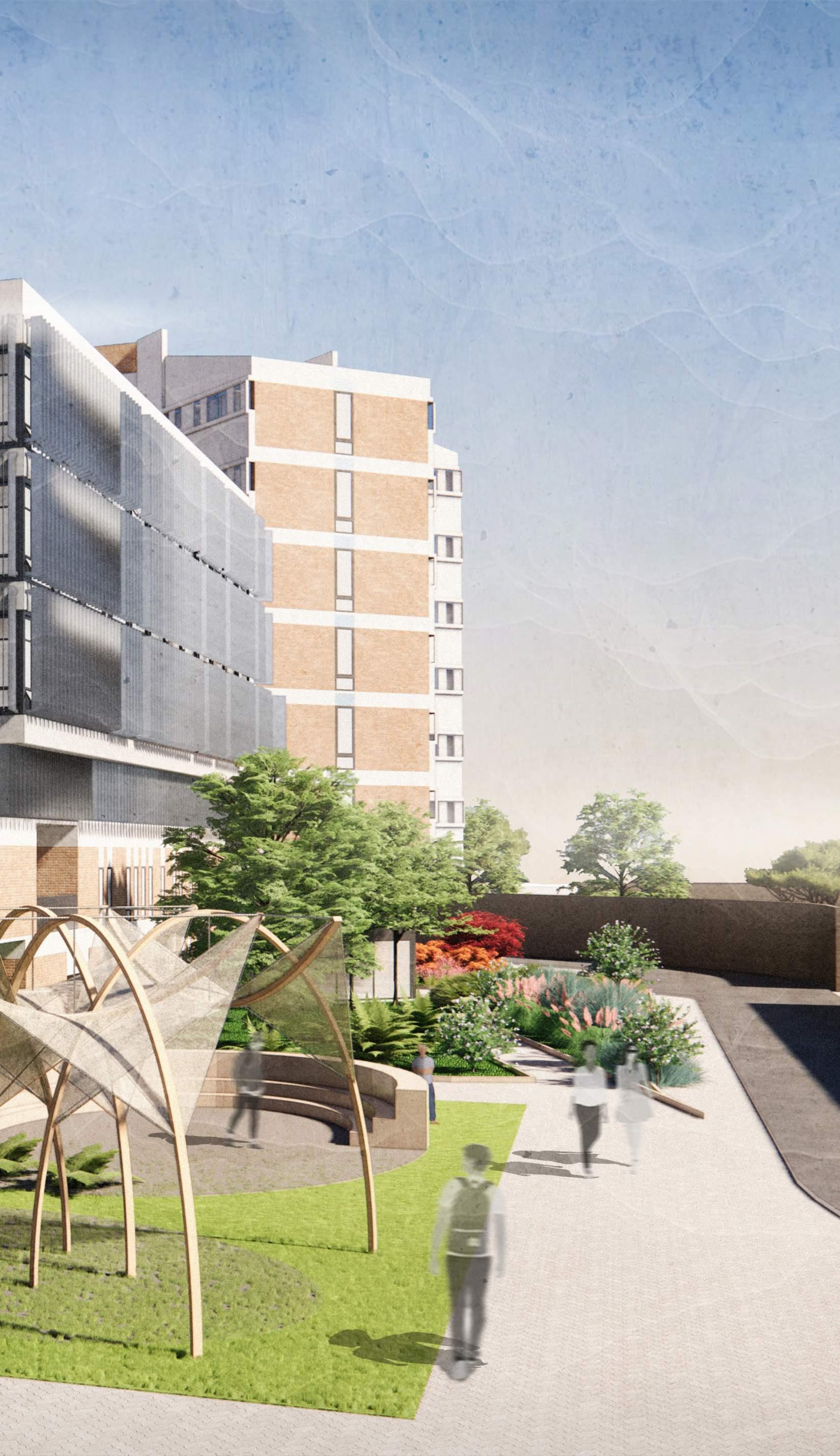
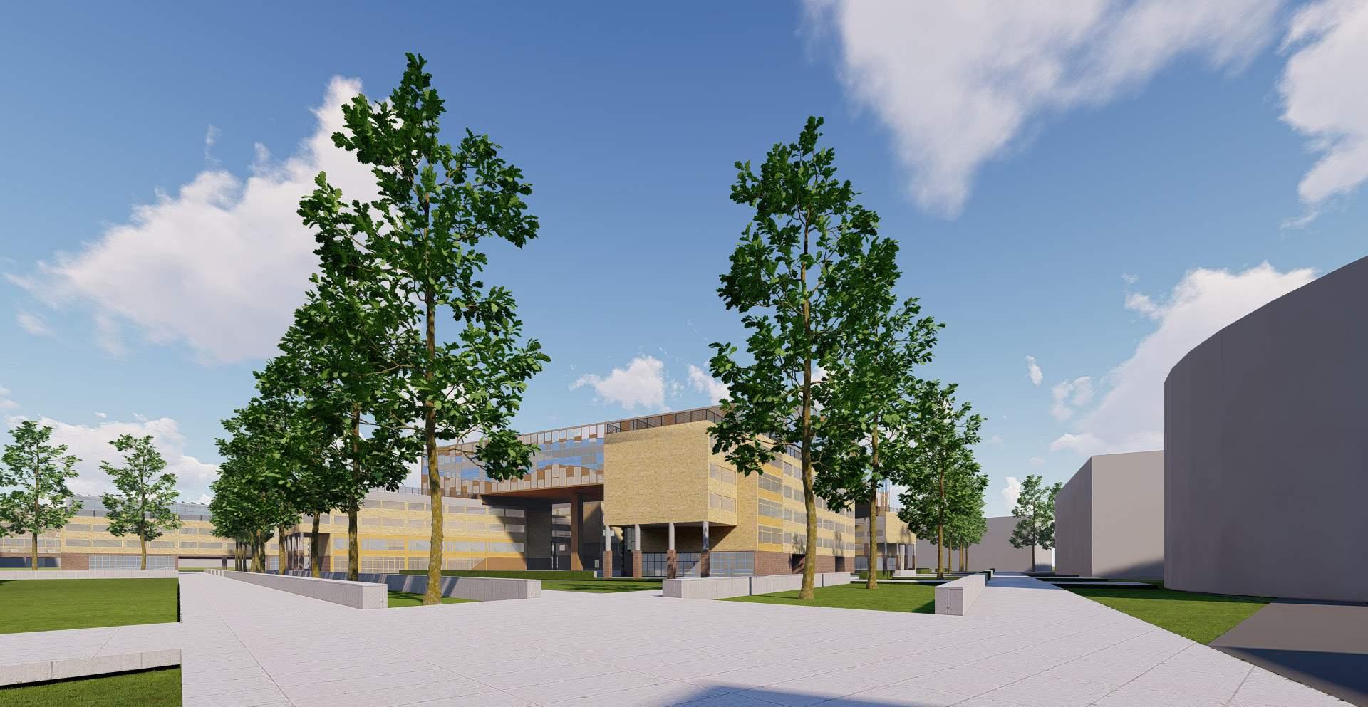
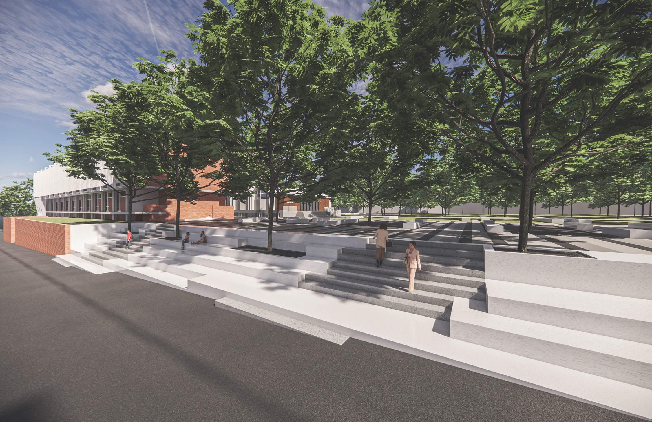
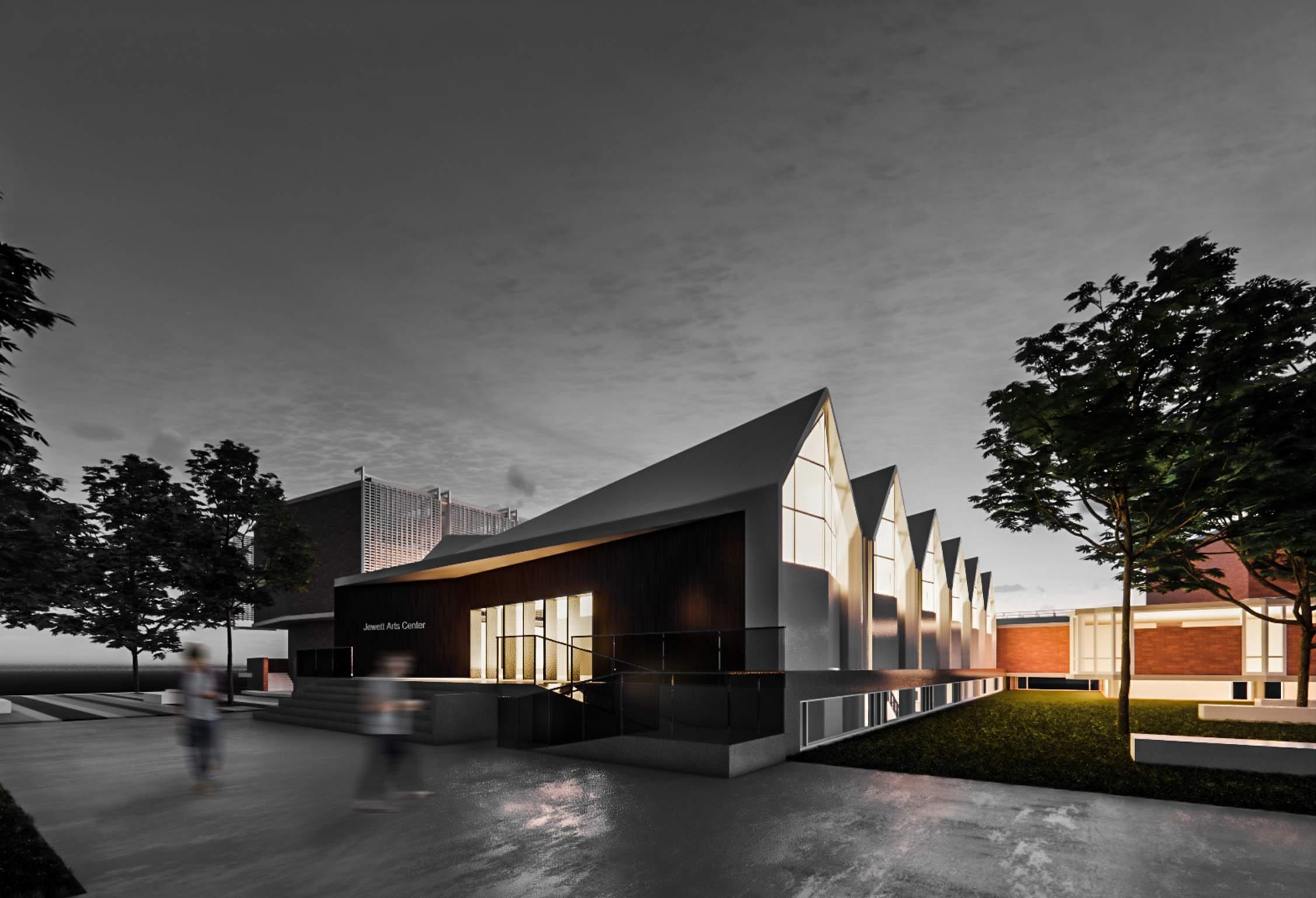
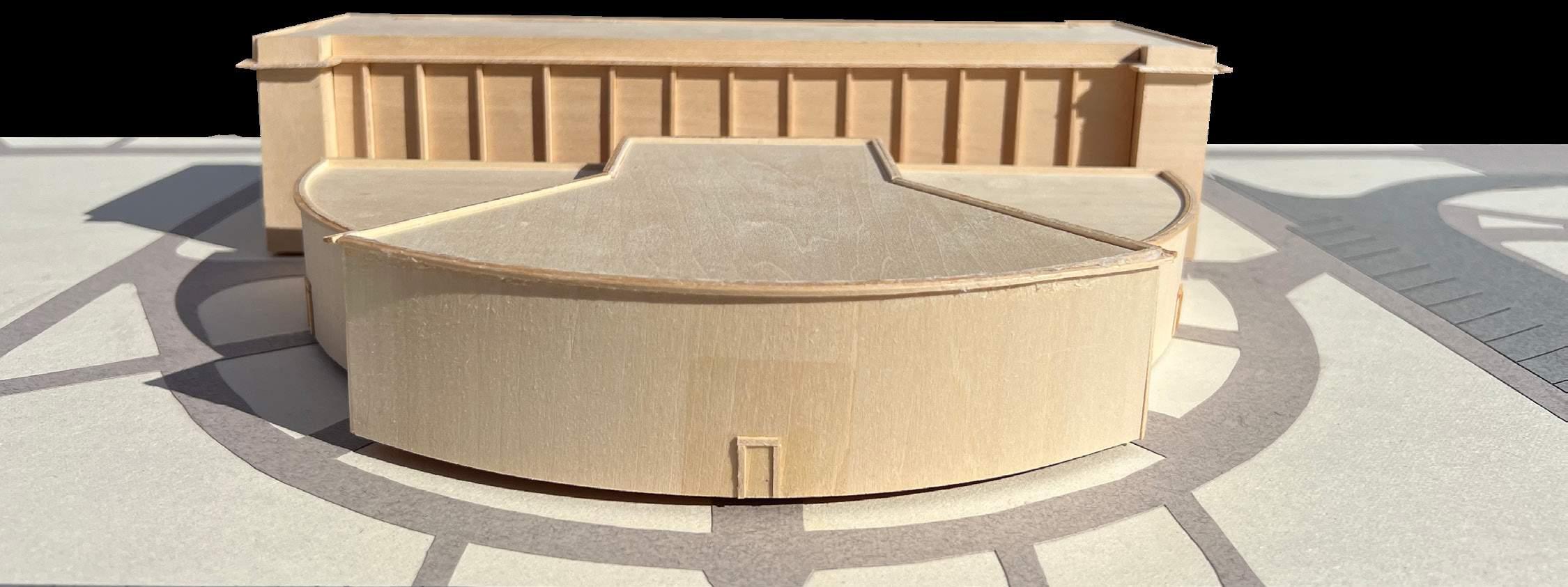
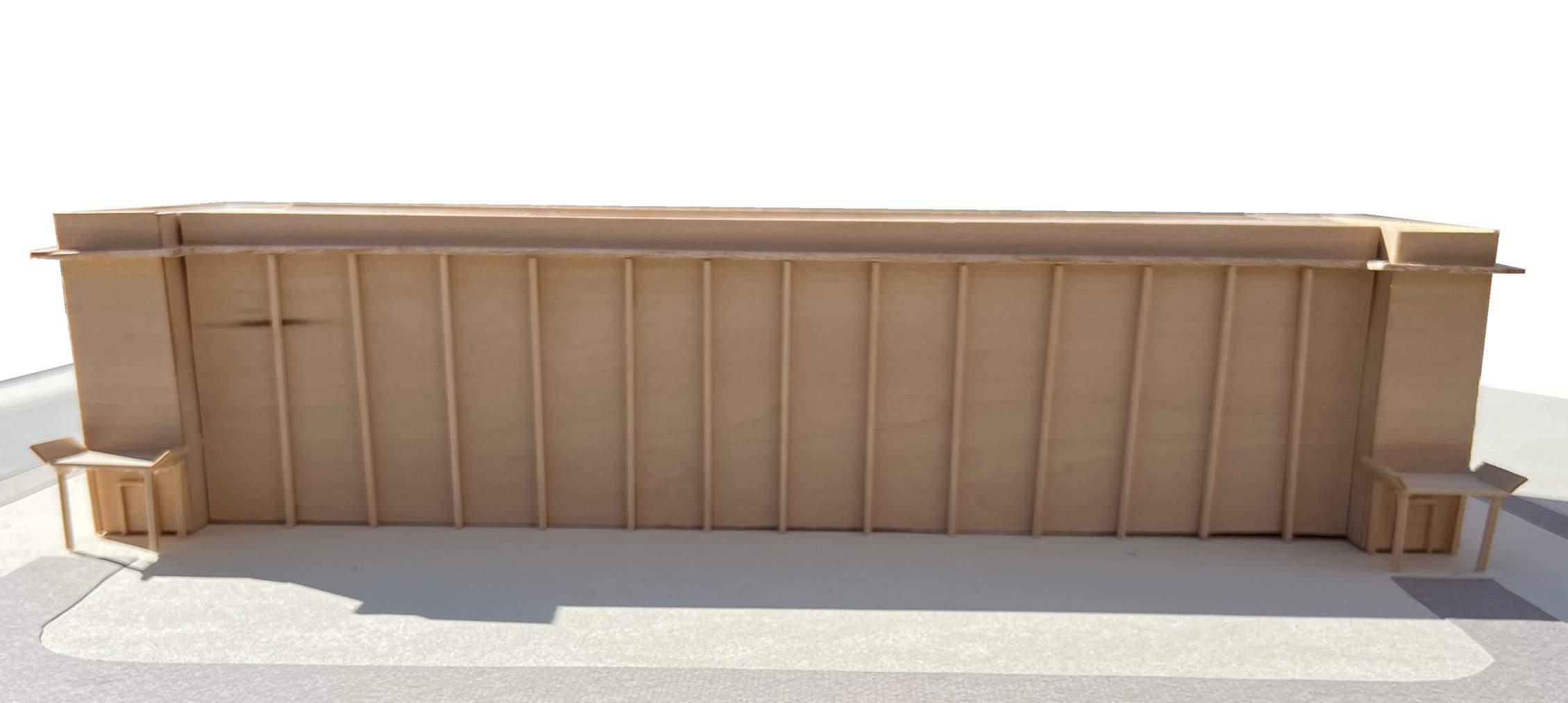
The view shows the north east entrance of the building.
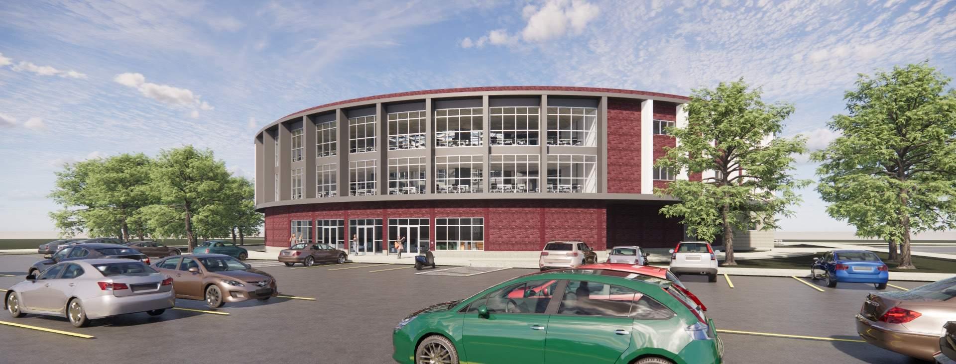
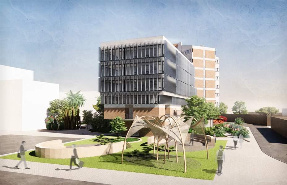
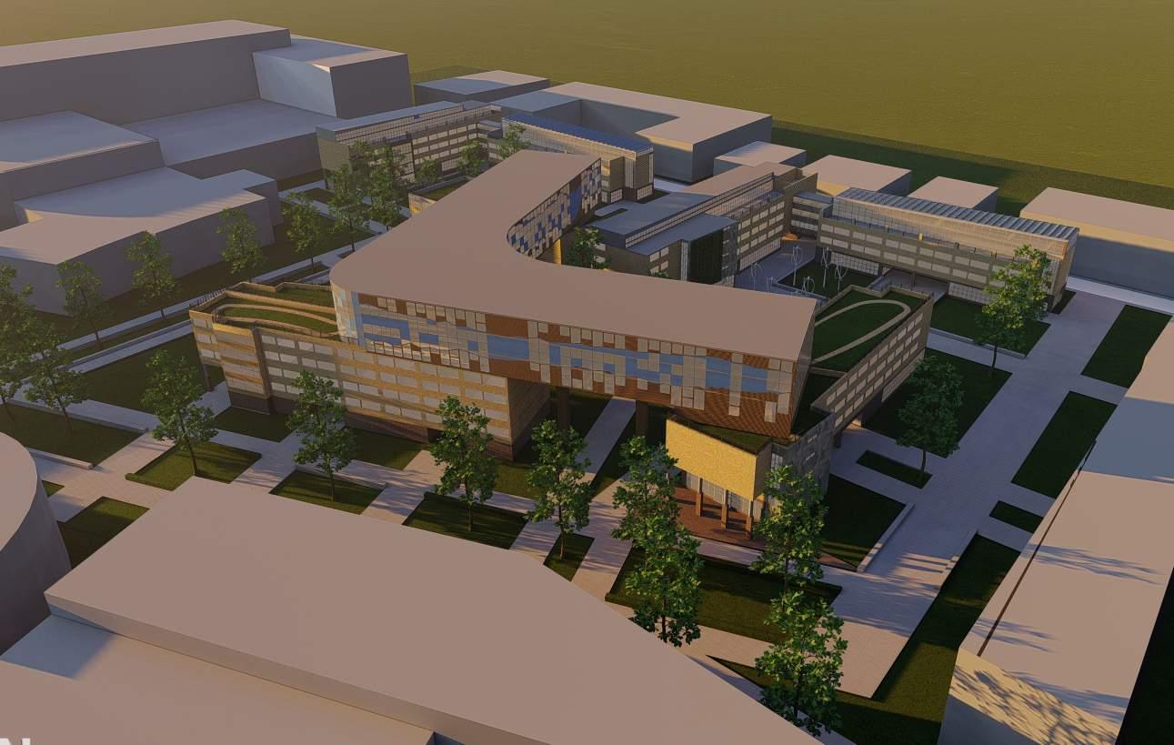
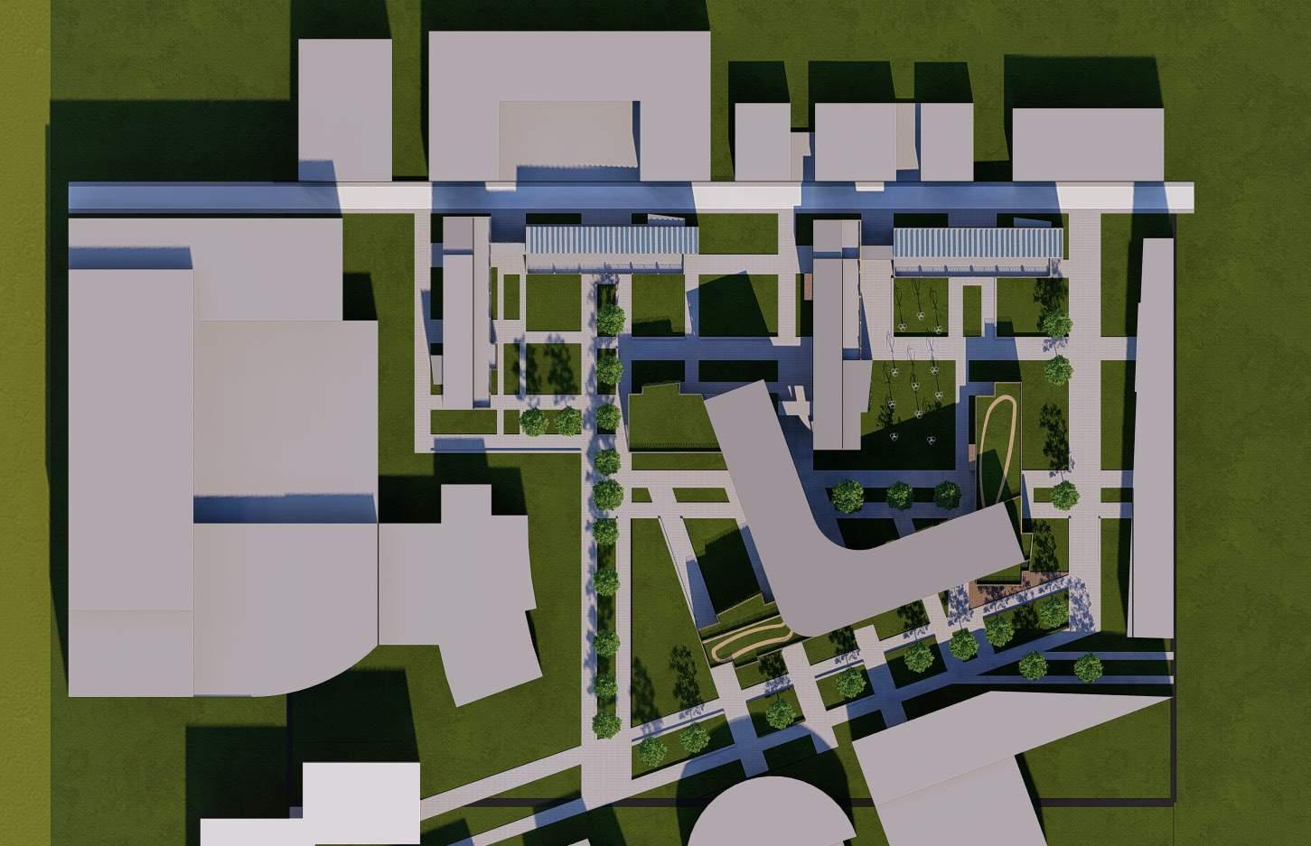
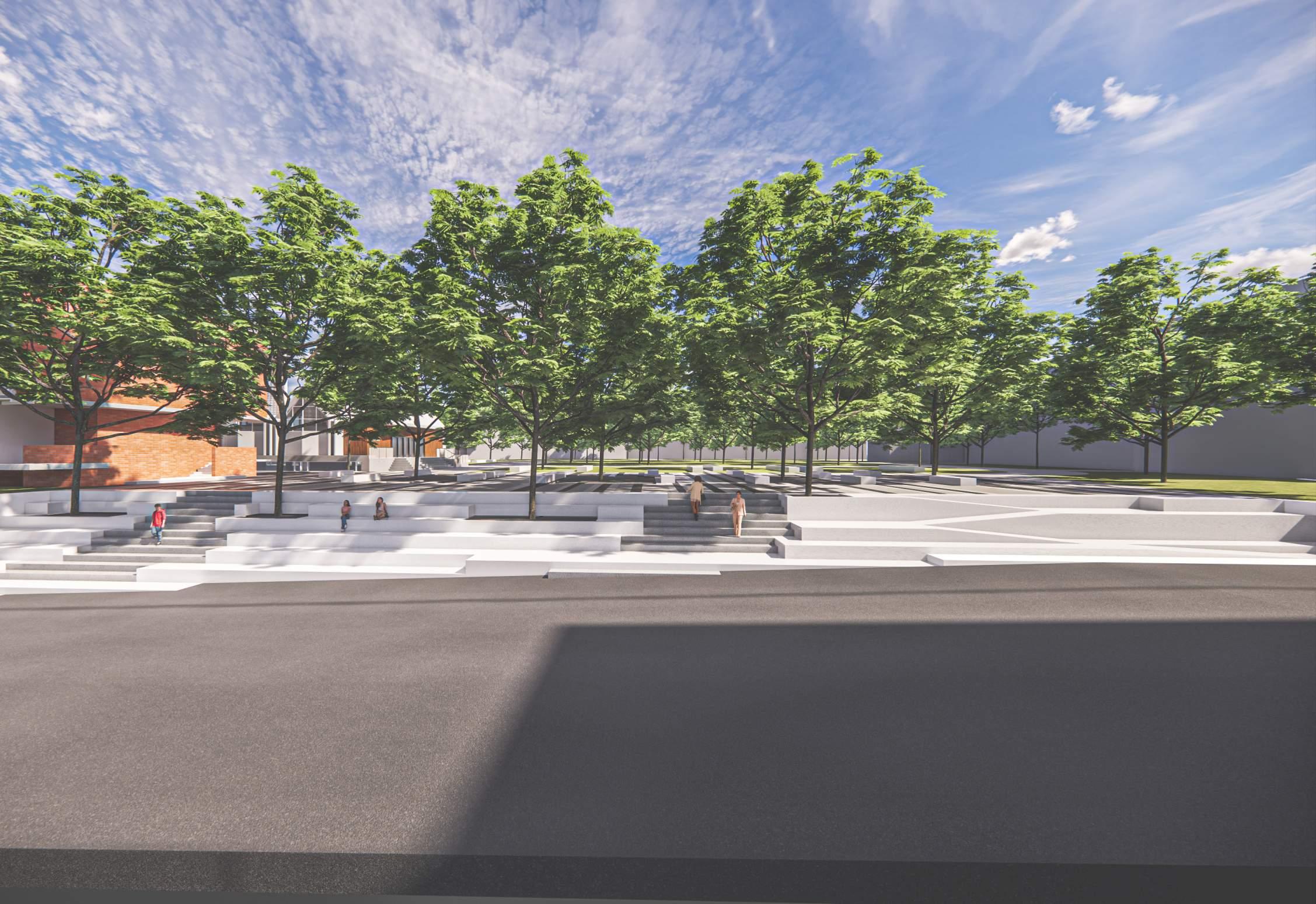
The view shows the overall site with the context and the expansion.
The proposal focuses on relating the site more towards outward and also still providing the thermal insulation inside the building.
The expansion is thought as the complimenting entity to the existing.
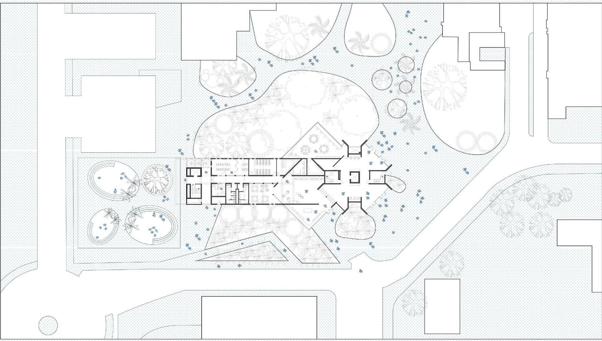
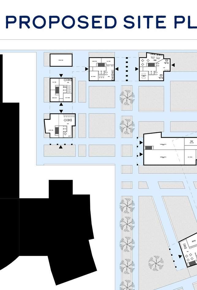
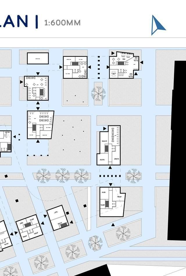
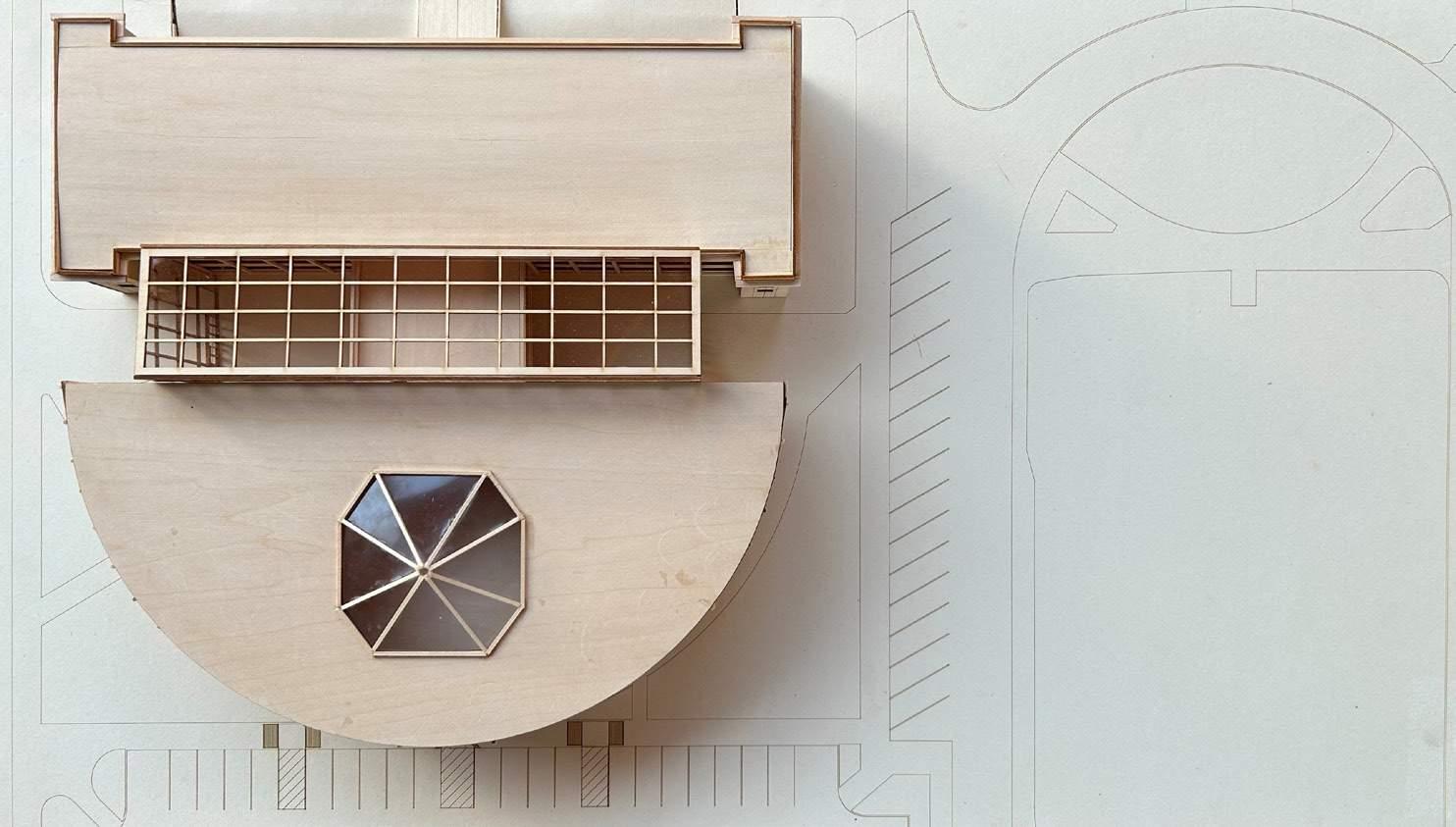
1. Folly 2. South entry 3. Entry 4. Walkway 5. Layered Landscape for privacy 6. Approach to the site from west 7. Vehicle accessible road 8.
Drop-off & cul-de-sac
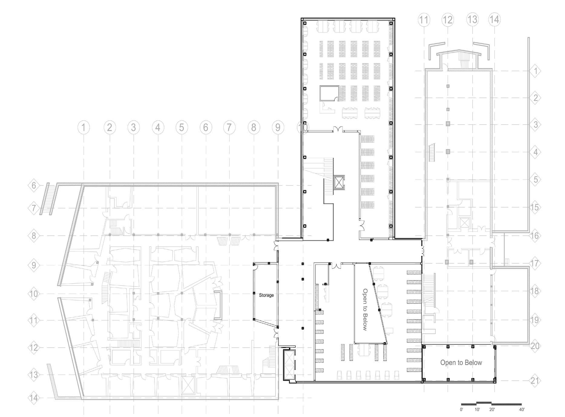
1. Elevator 2. Staircase 3. Mail room 4. Conference and meeting room 5. Office 6. Equipment room 7. Female washroom 8. Male washroom 9.
Discussion room 10. Collaborative classroom 11. File room 12. Control room 13. Equipment storage room 14. Storage 15.
Collaborative work spaces 16. Collaborative Labs 17. Computer desks 18. Information desk 19. Staircase 20. Elevator 21. Duct
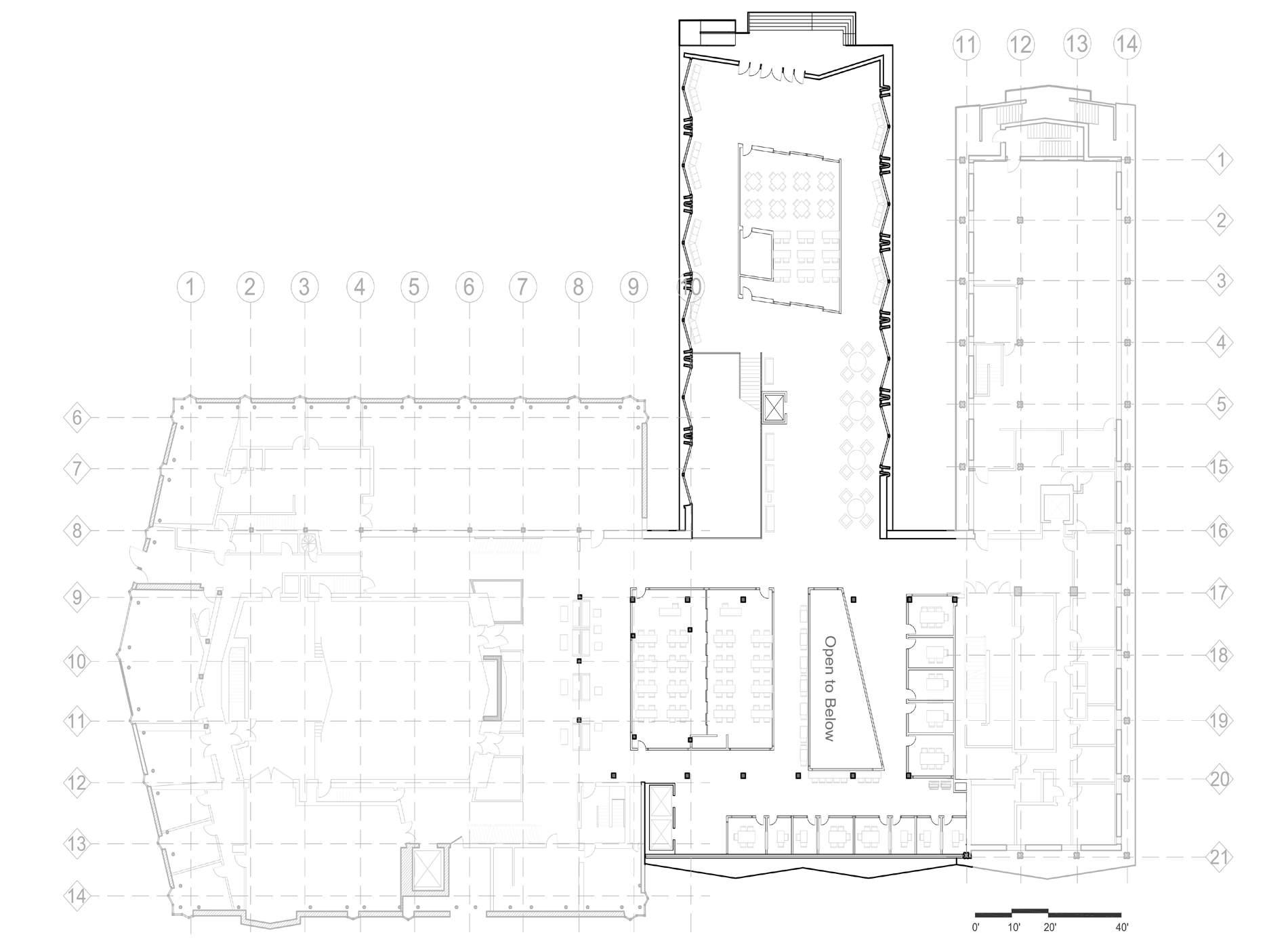
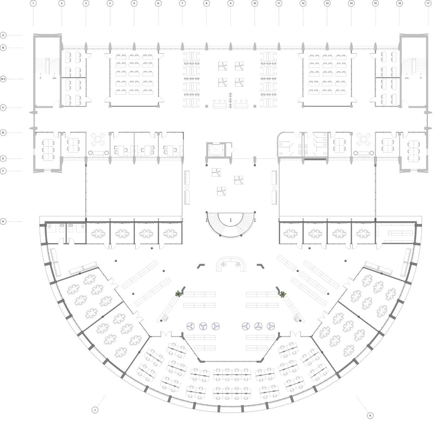
1. Elevator 2. Staircase 3. Workstation 4. Library 5. Reading room 6. Atrium 7. Offices 8. Meeting rooms 9. Toilets
1. Elevator 2. Staircase 3. Collaborative discussion areas 4. Reading room 6. Balcony 7. Offices 8. Meeting rooms 9. Toilets
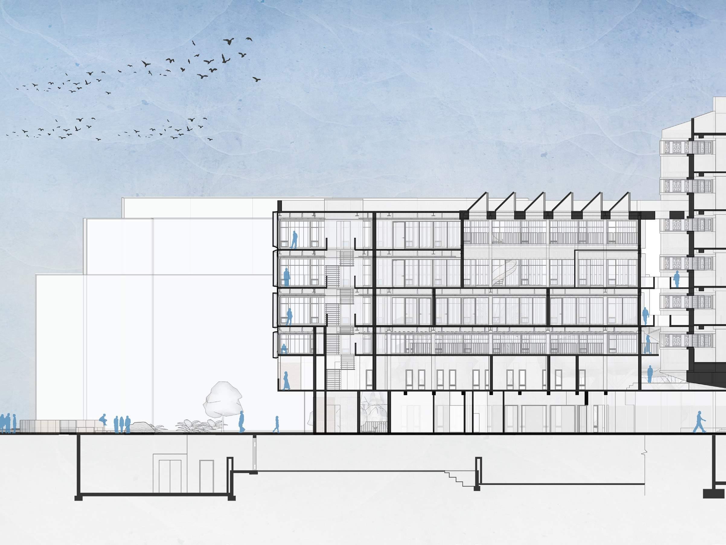
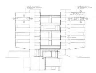
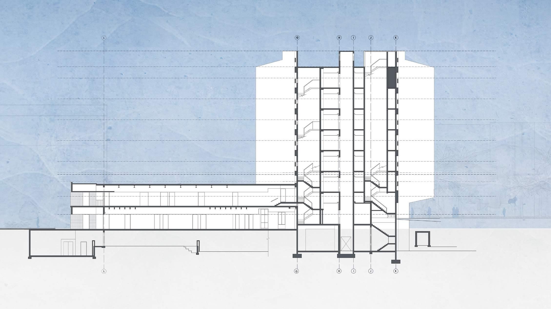
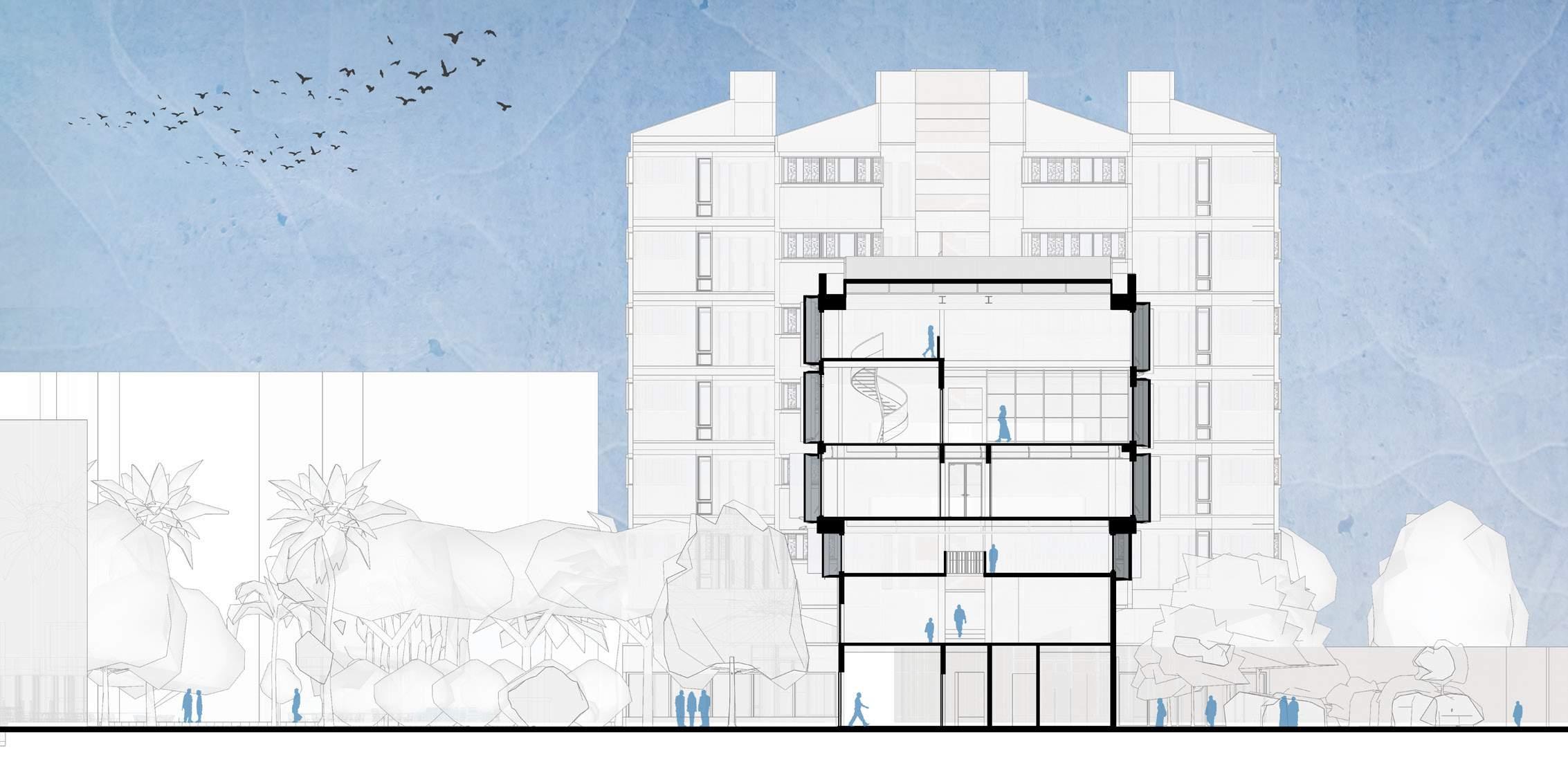
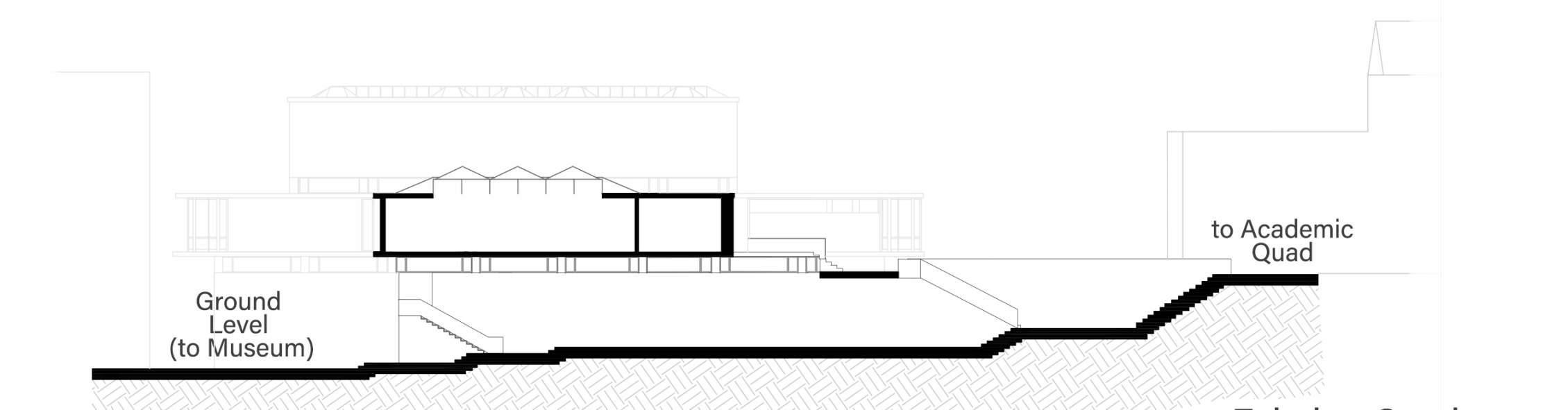
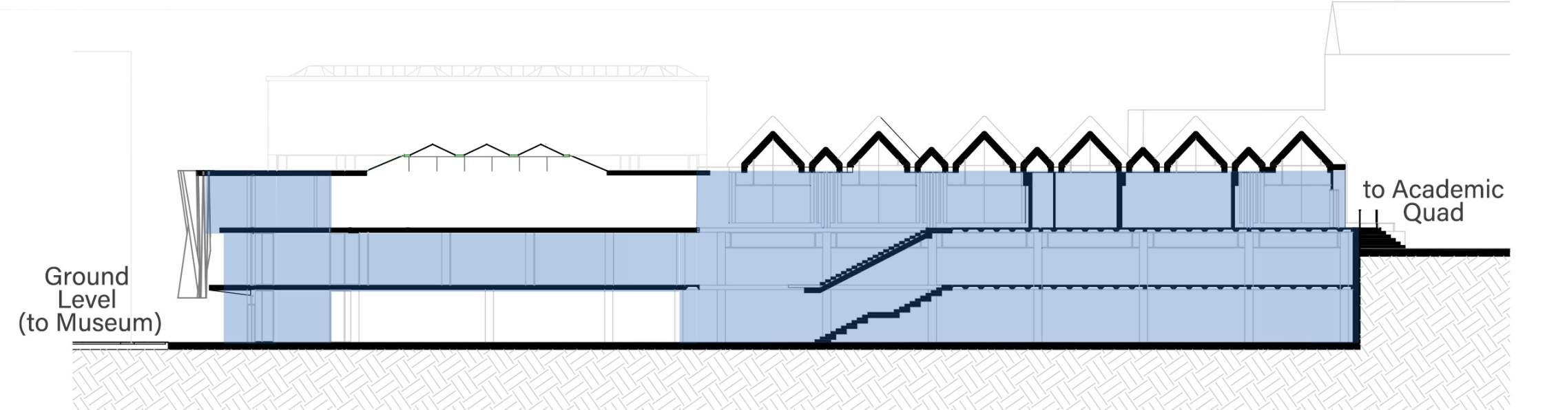
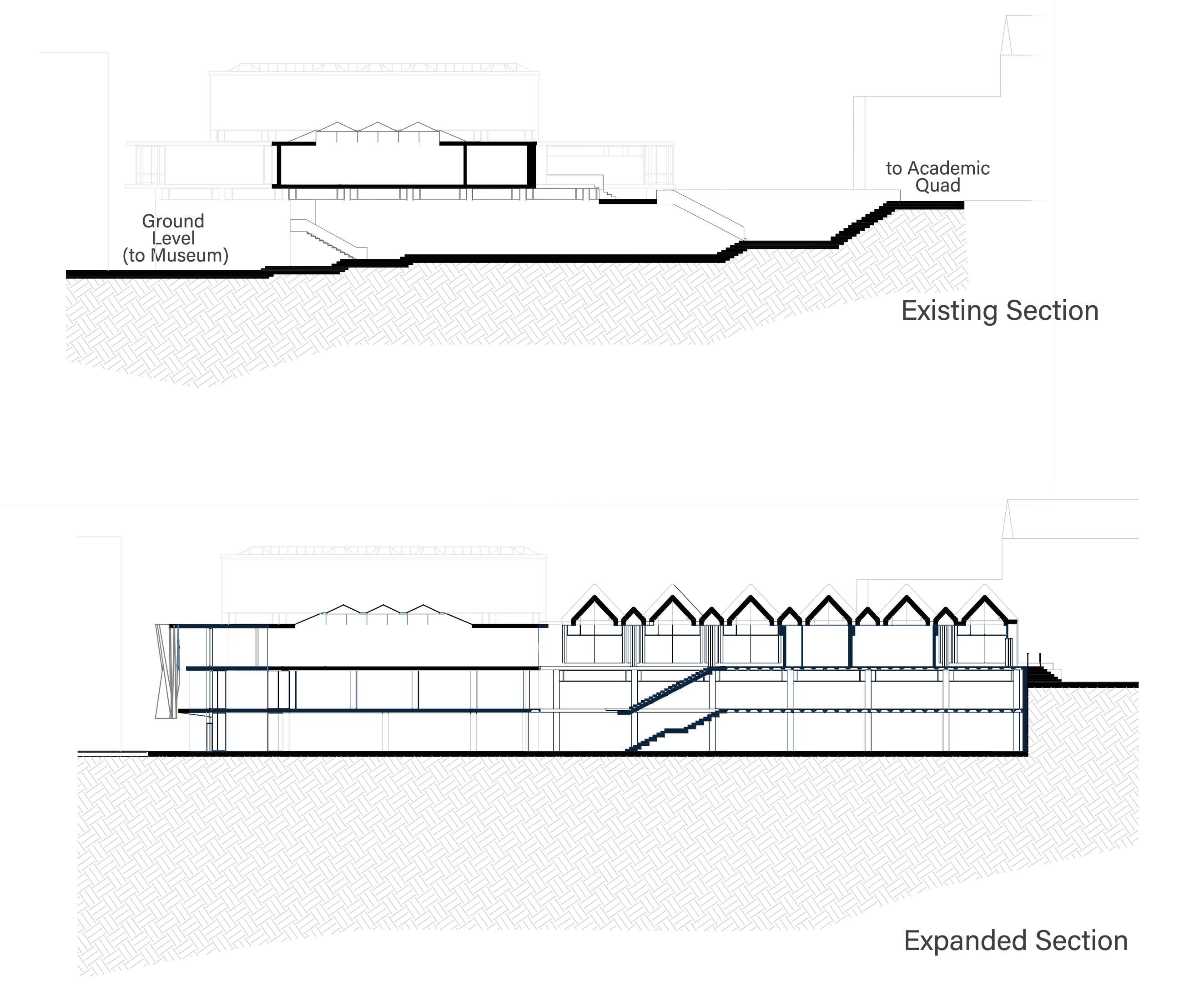
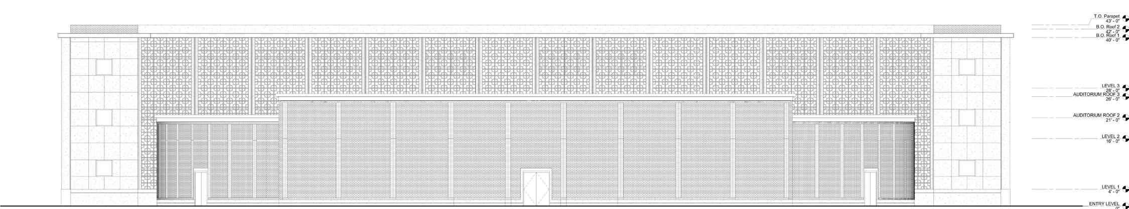
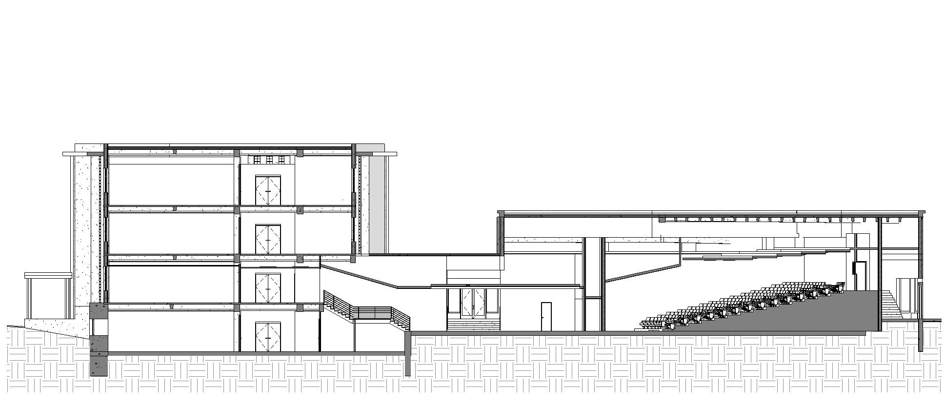
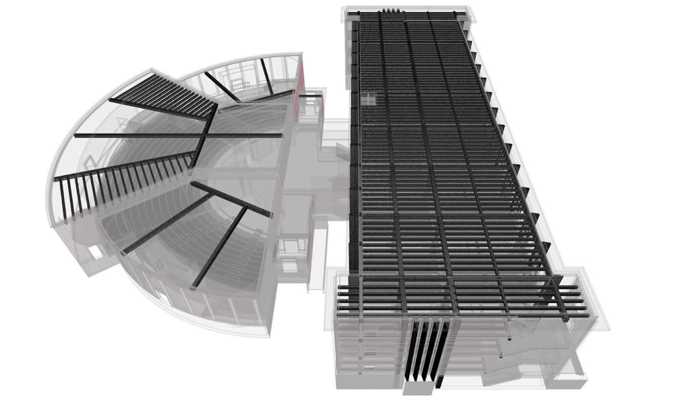
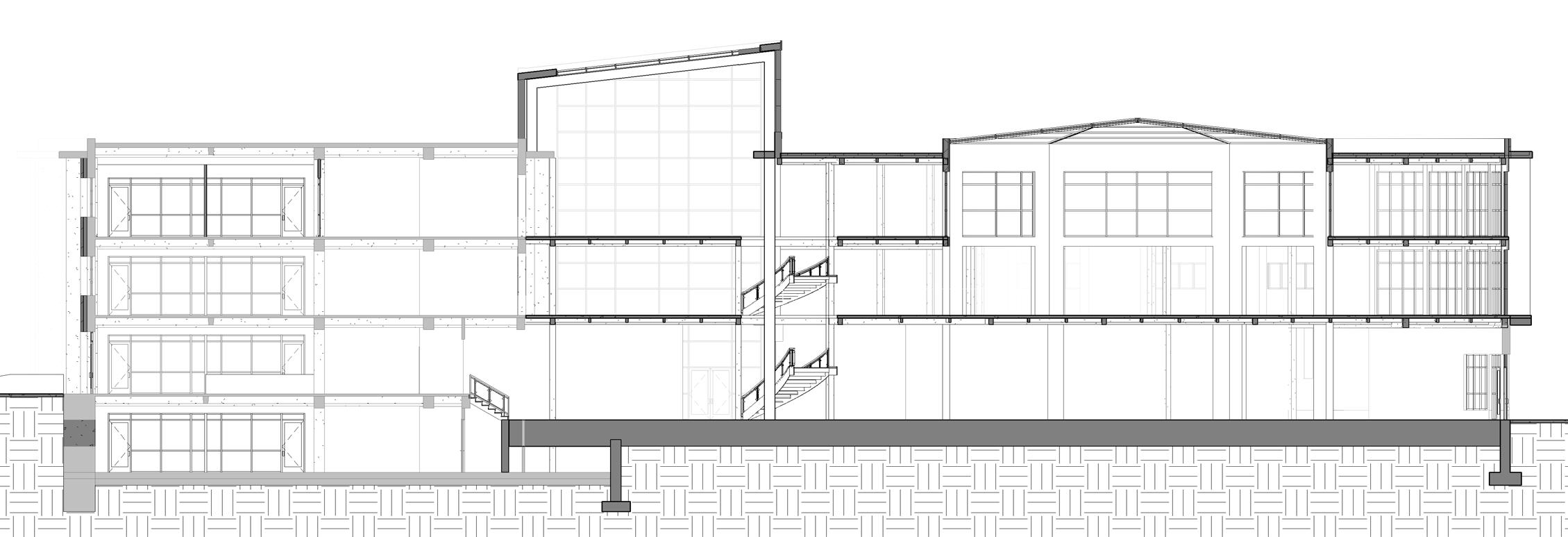
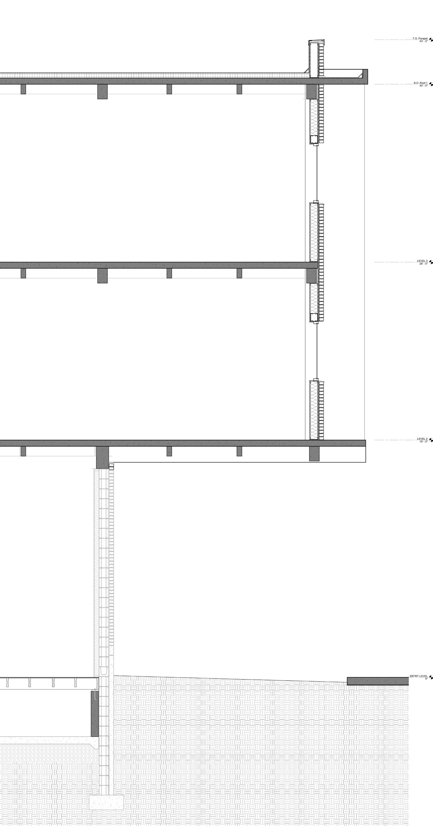
The section tries capturing the overall connection of the site on the ground and on the south side towards the folly. It shows magazine floors and the solar roof top. It also tries to show the connection between the expansion and the adaptation.
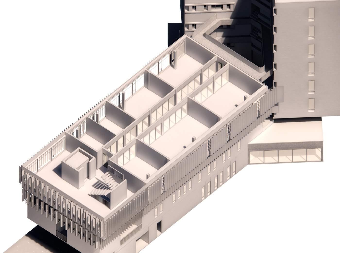
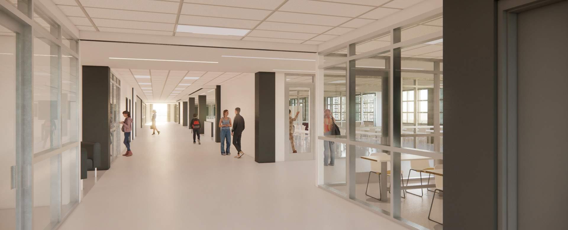
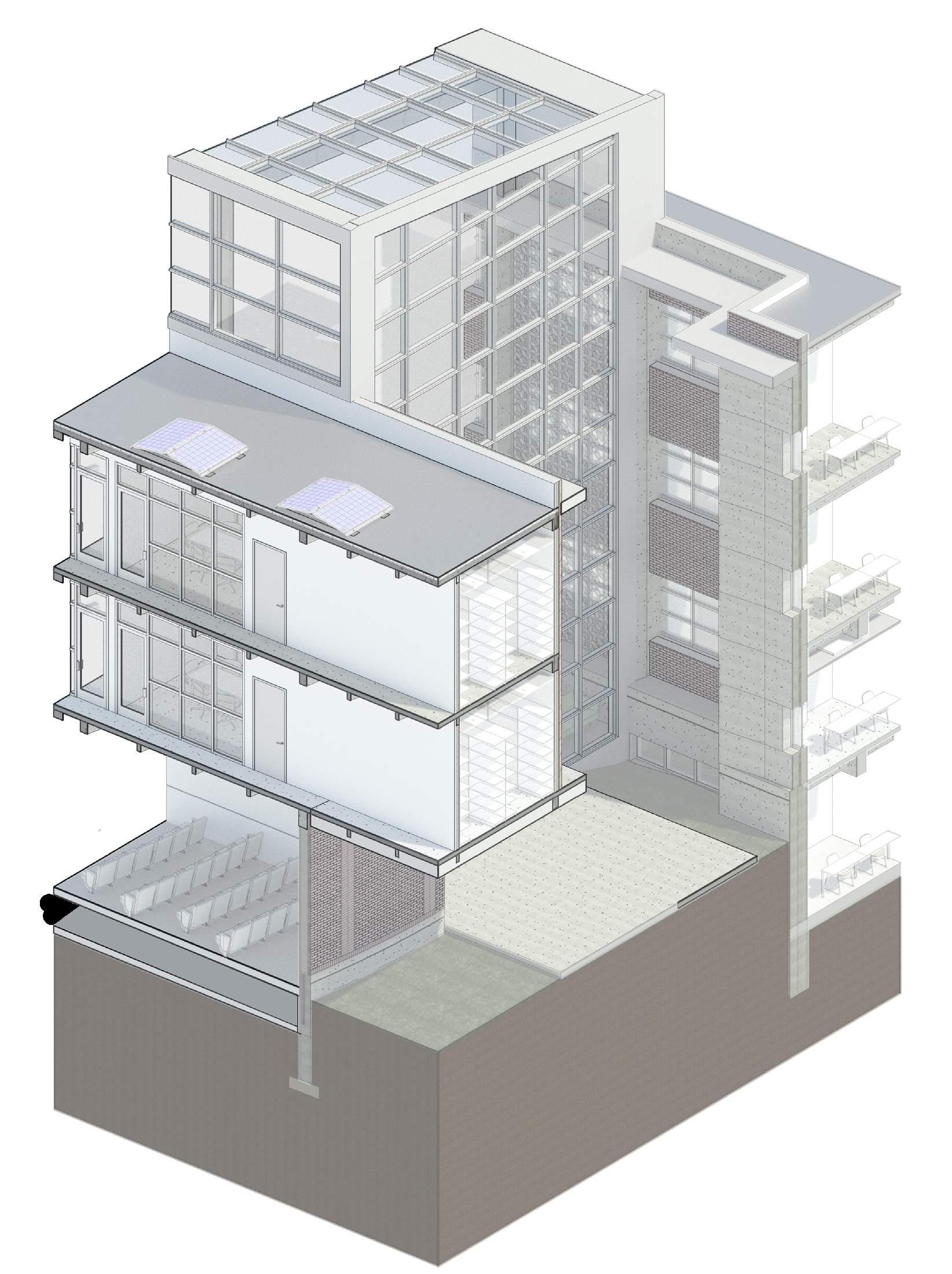
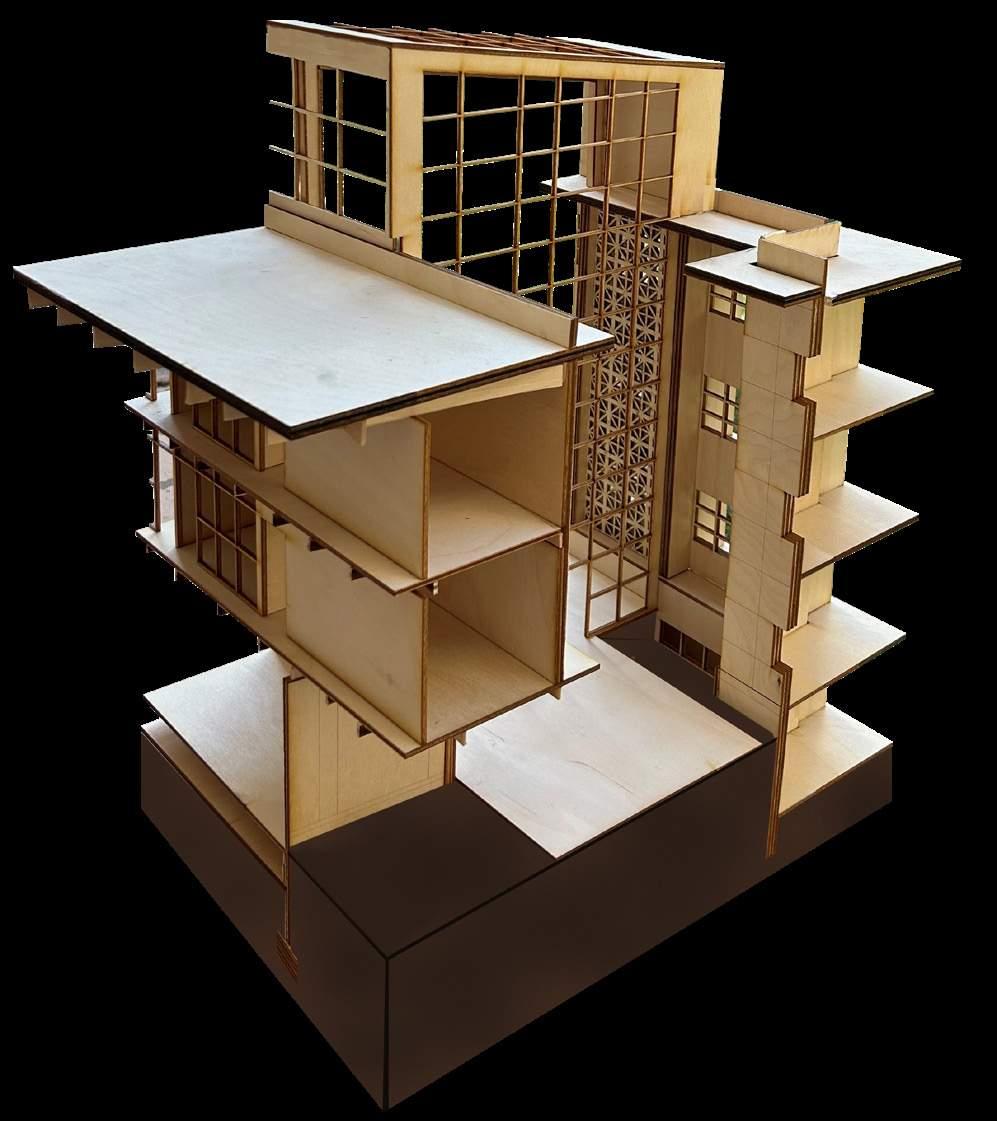
The axon shows the classroom and the transparency towards outside and the cores.
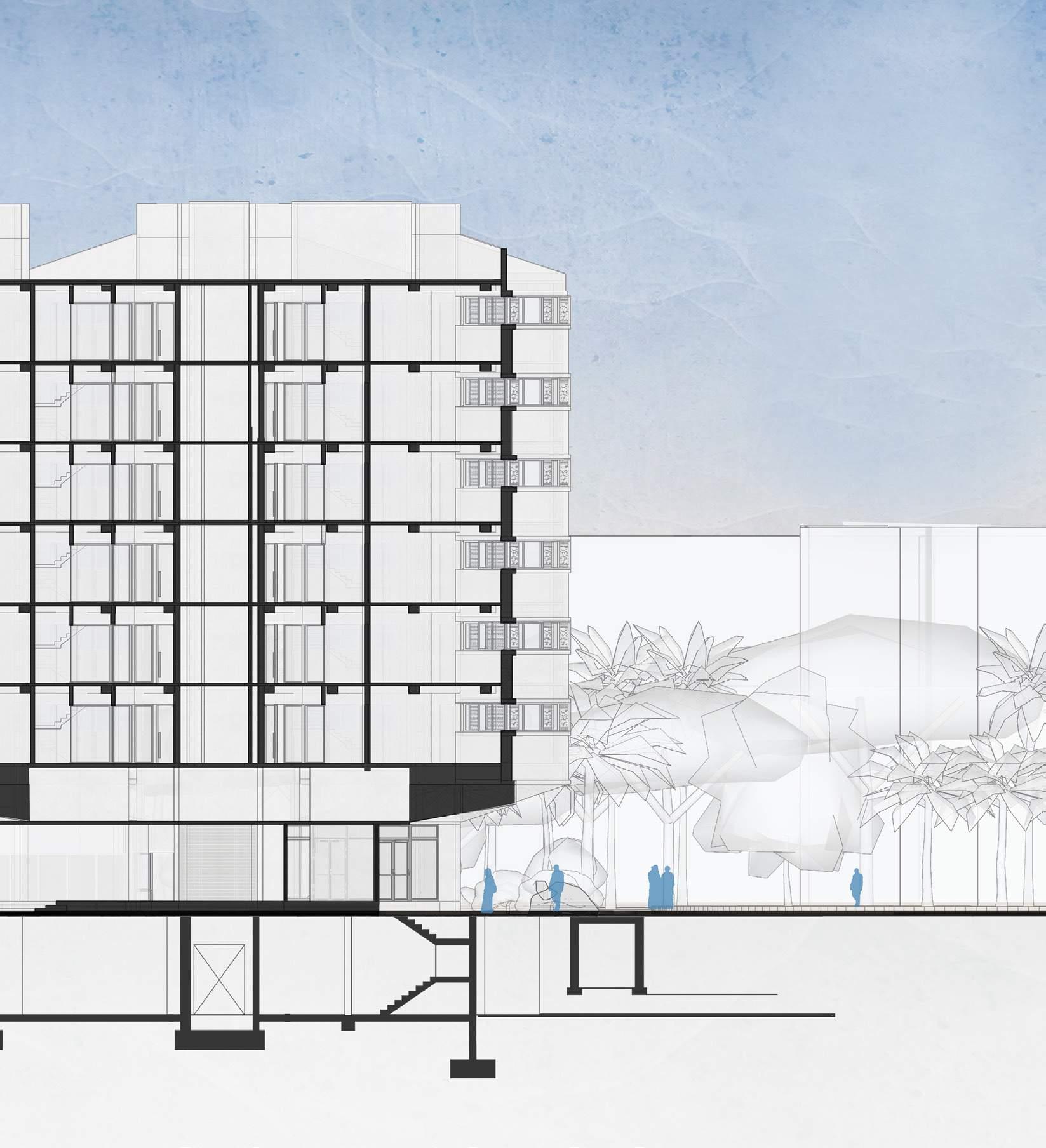
The section from the south emphasis on the facade, the mezzanine floors on different levels. It also shows the connections on the ground.
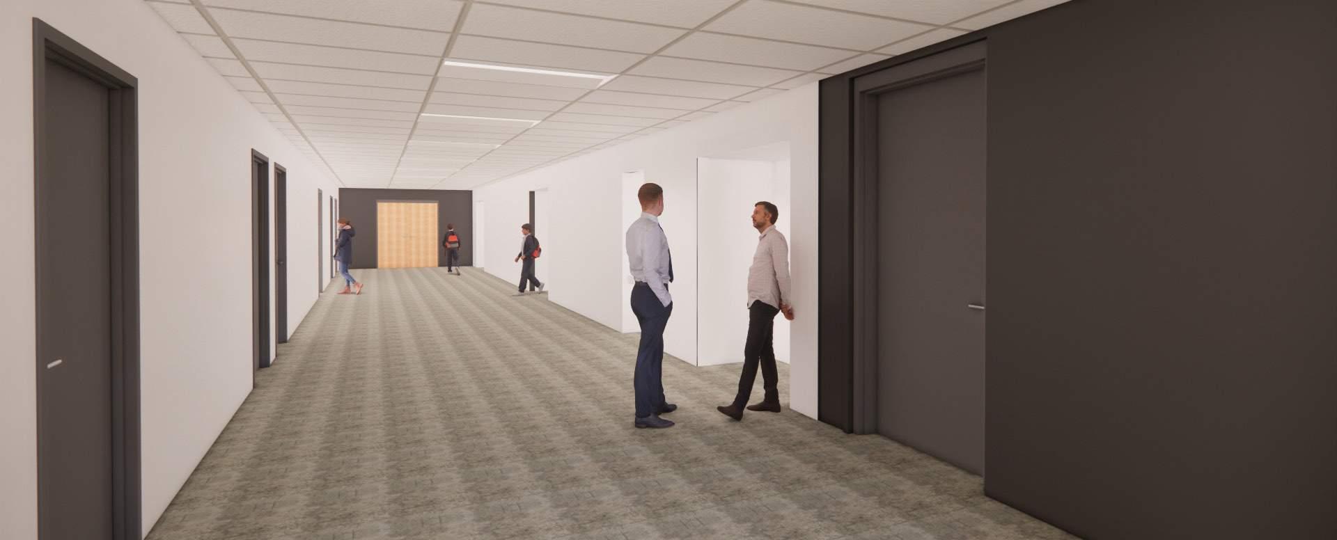
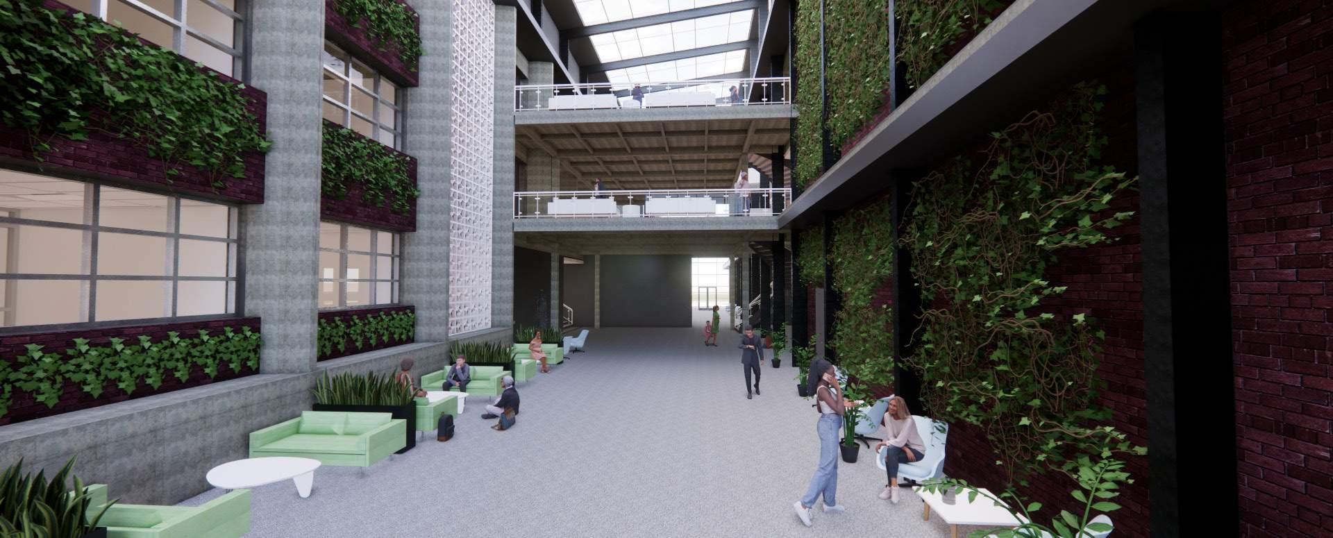
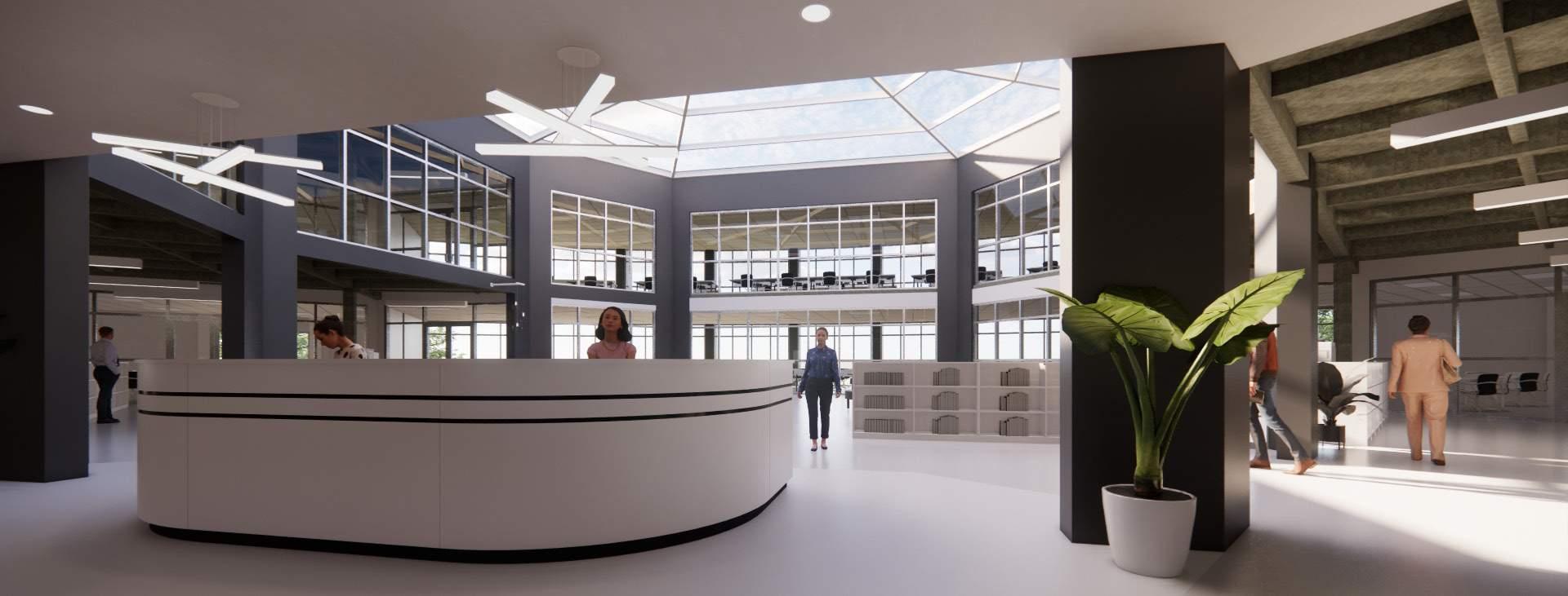
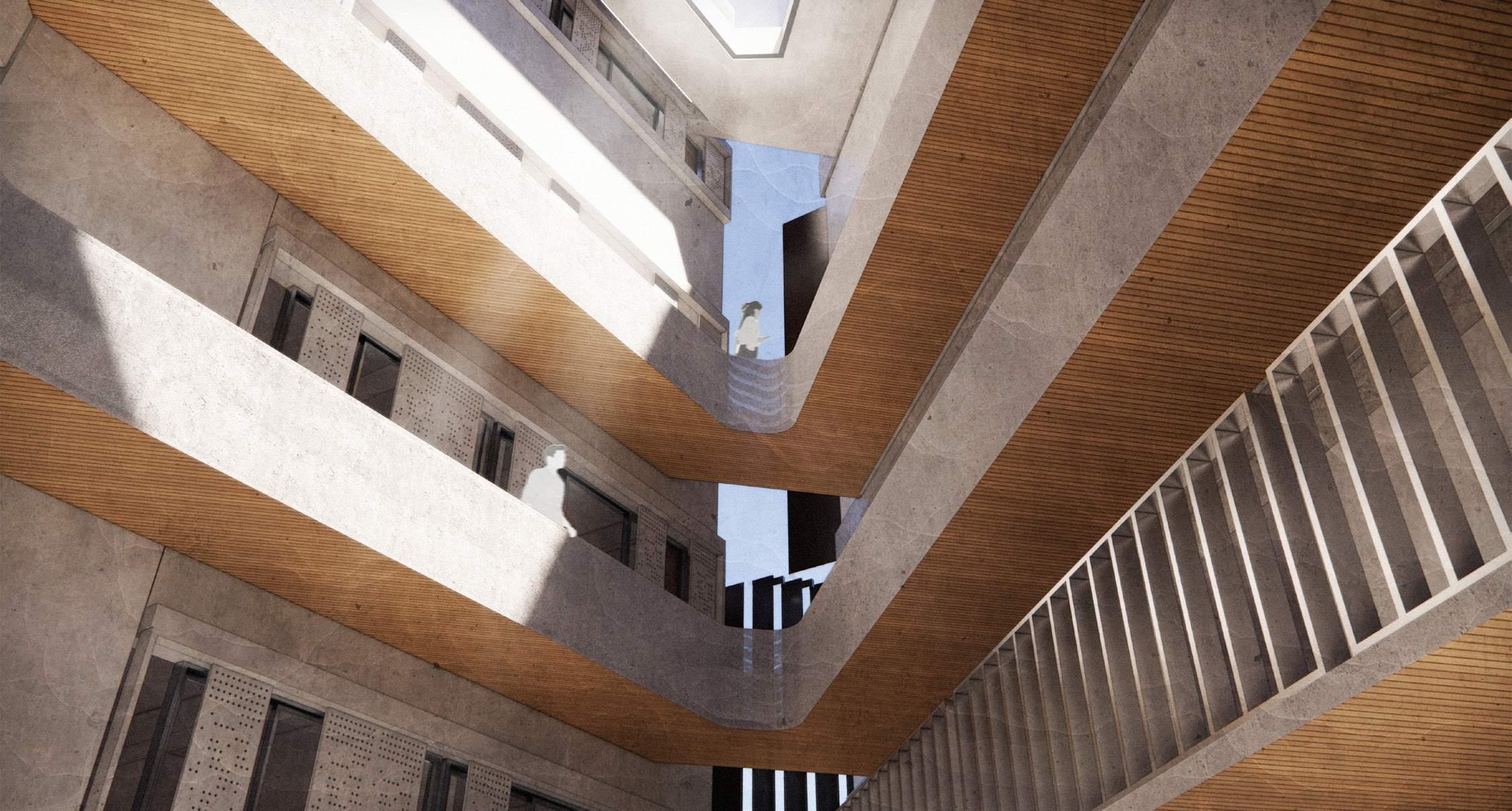
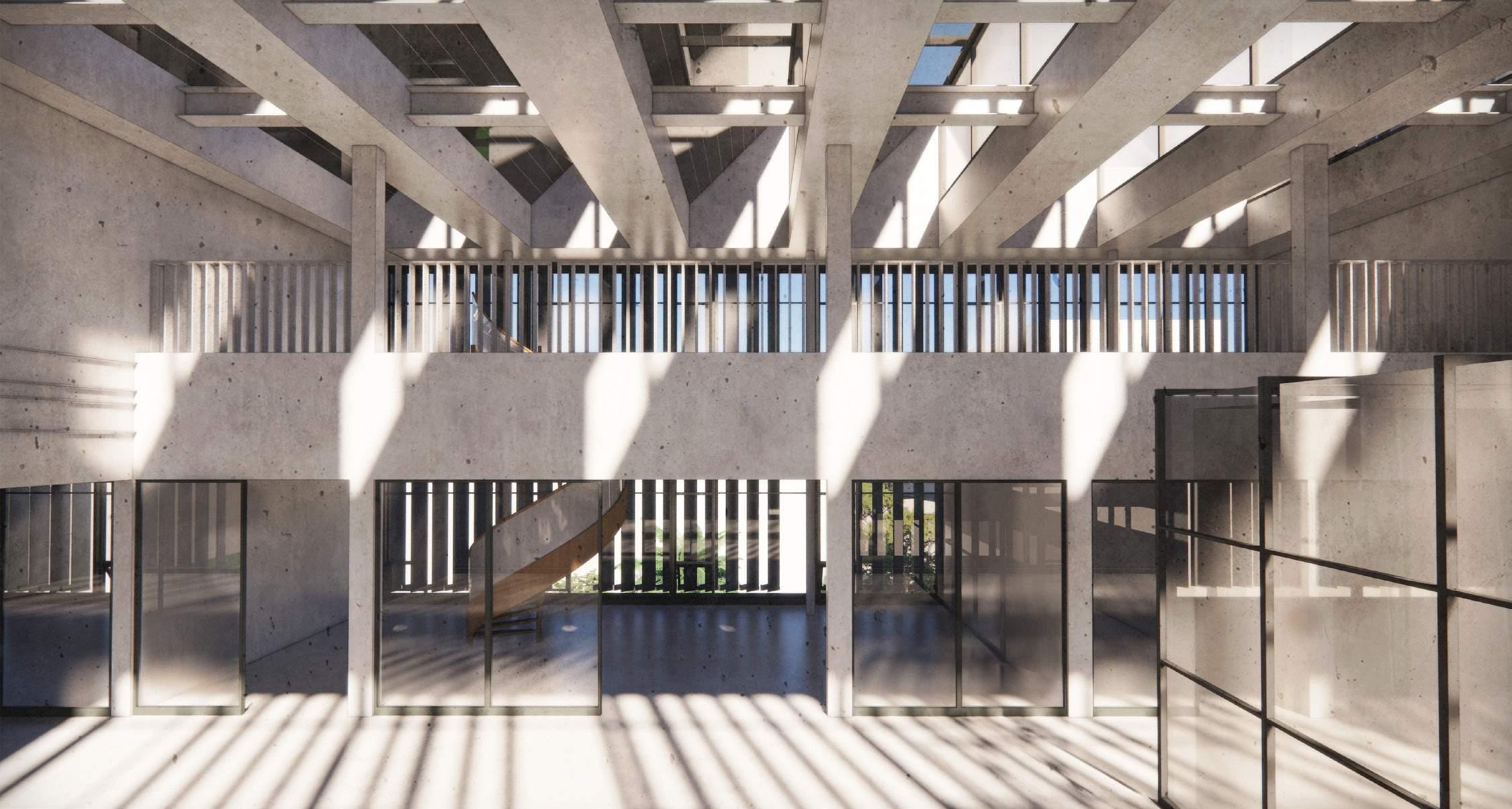
The view from the atrium tries to capture the vastness due to the height and the corridors forming the
part to communicate at different levels.
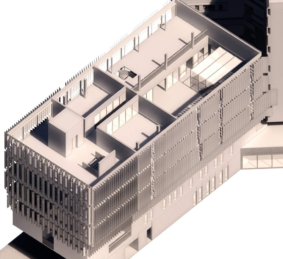
The axon shows the mezzanine floor on the fifth floor and the connection of it to the fourth floor.
The research lab is designed to capture the most of the sun and providing an collaborative
environment along with certain private labs housing in it. It tries to expose the structure inside as well
as the outside.
1. Elevator 2. Staircase 3. Collaborative discussion areas 4. Computer Lab 5. Tutor room 6. Research Lab 7. Circulation corridor
8. Offices 9. Meeting rooms 10. Toilets
1. Elevator 2. Staircase 3. Collaborative discussion areas 4. Computer Lab 6. Research Lab 7.
Balcony 8. Offices 9. Meeting rooms 10. Toilets
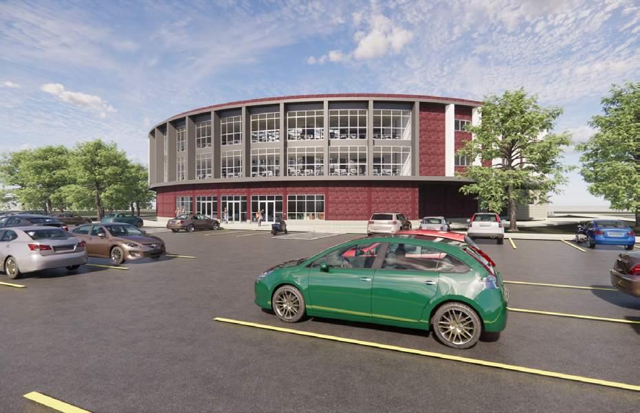
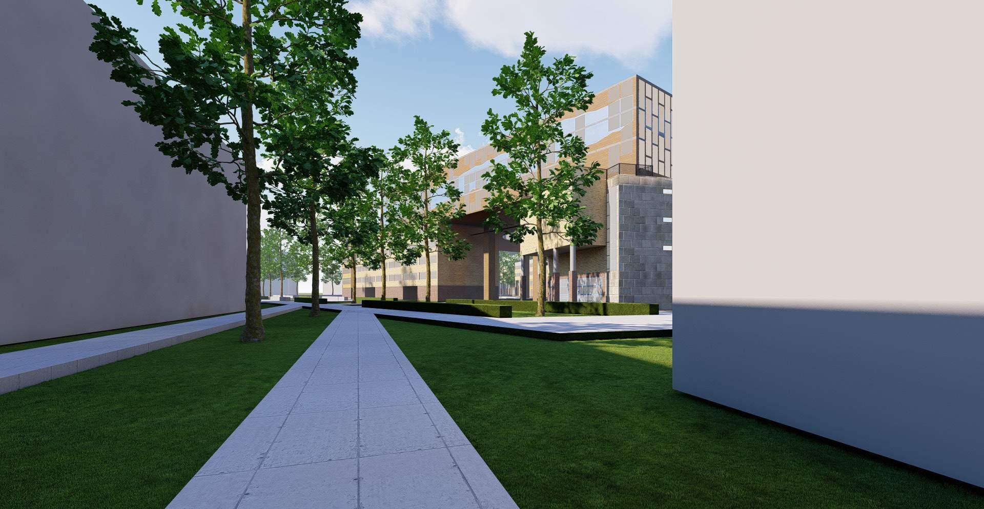
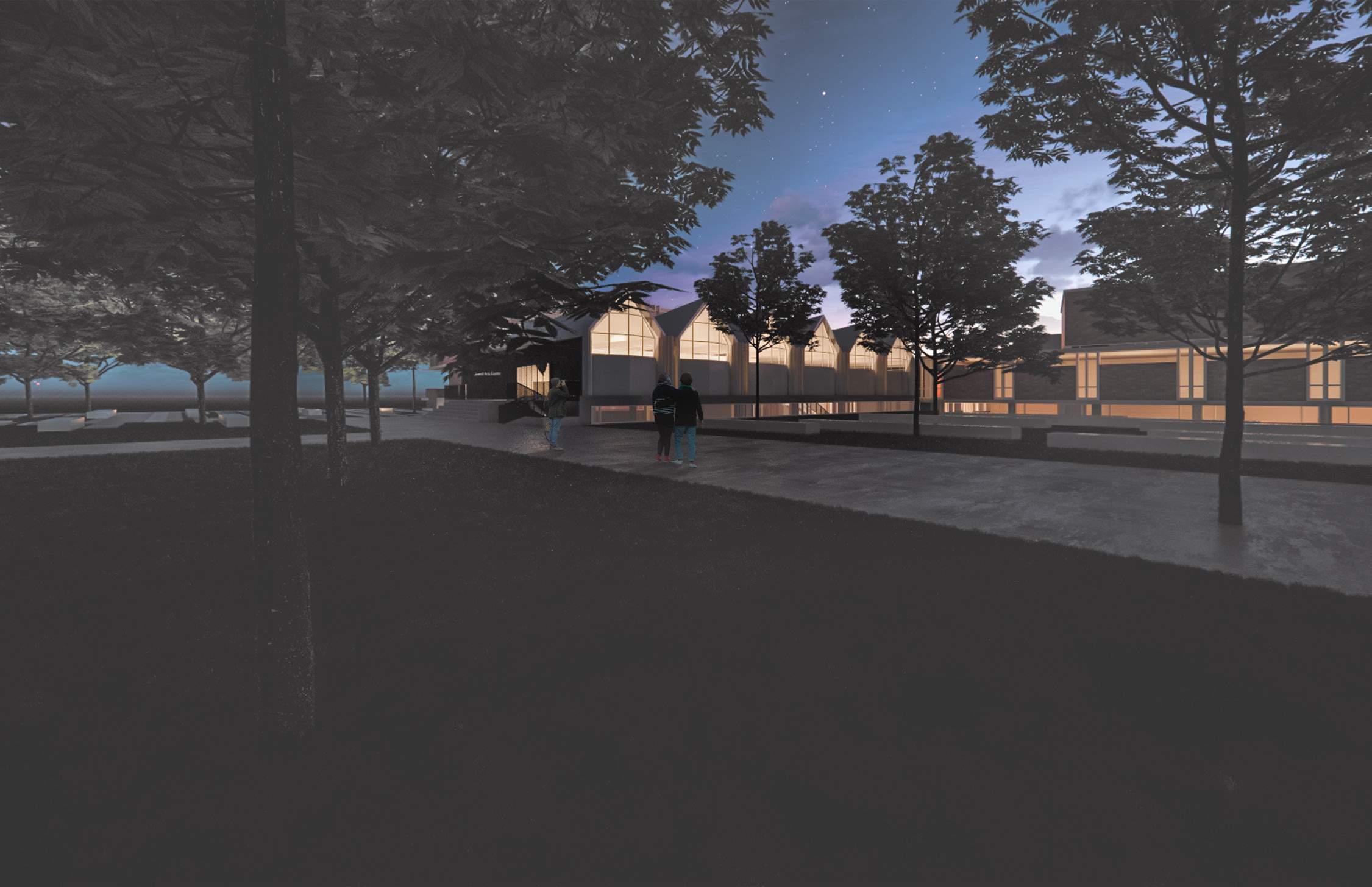
East view shows the layered landscape and the glass box on the ground floor which allows the
student community to look into the building trying to move away from the dead walled street on that side.
Legend:
1. Elevator 2. Staircase 3. Offices 4. Meeting rooms 5. Toilets
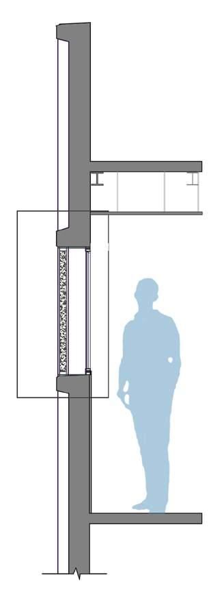
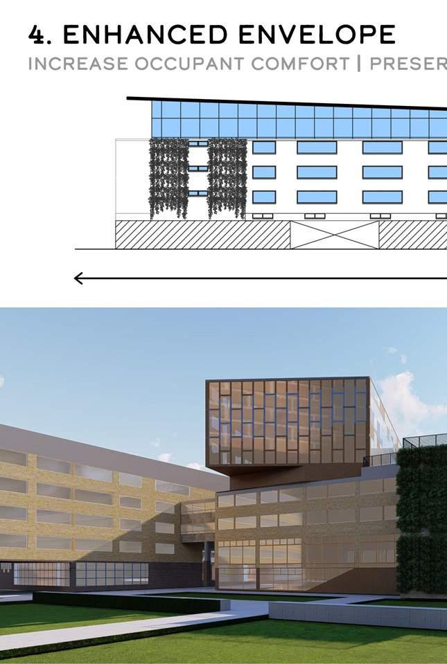
The detail shows the variation of the existing opening and providing the sliding windows with the concrete lattice infill on the outside provided the thermal insulation in the middle.
The detail shows the elevation of the concrete infills.
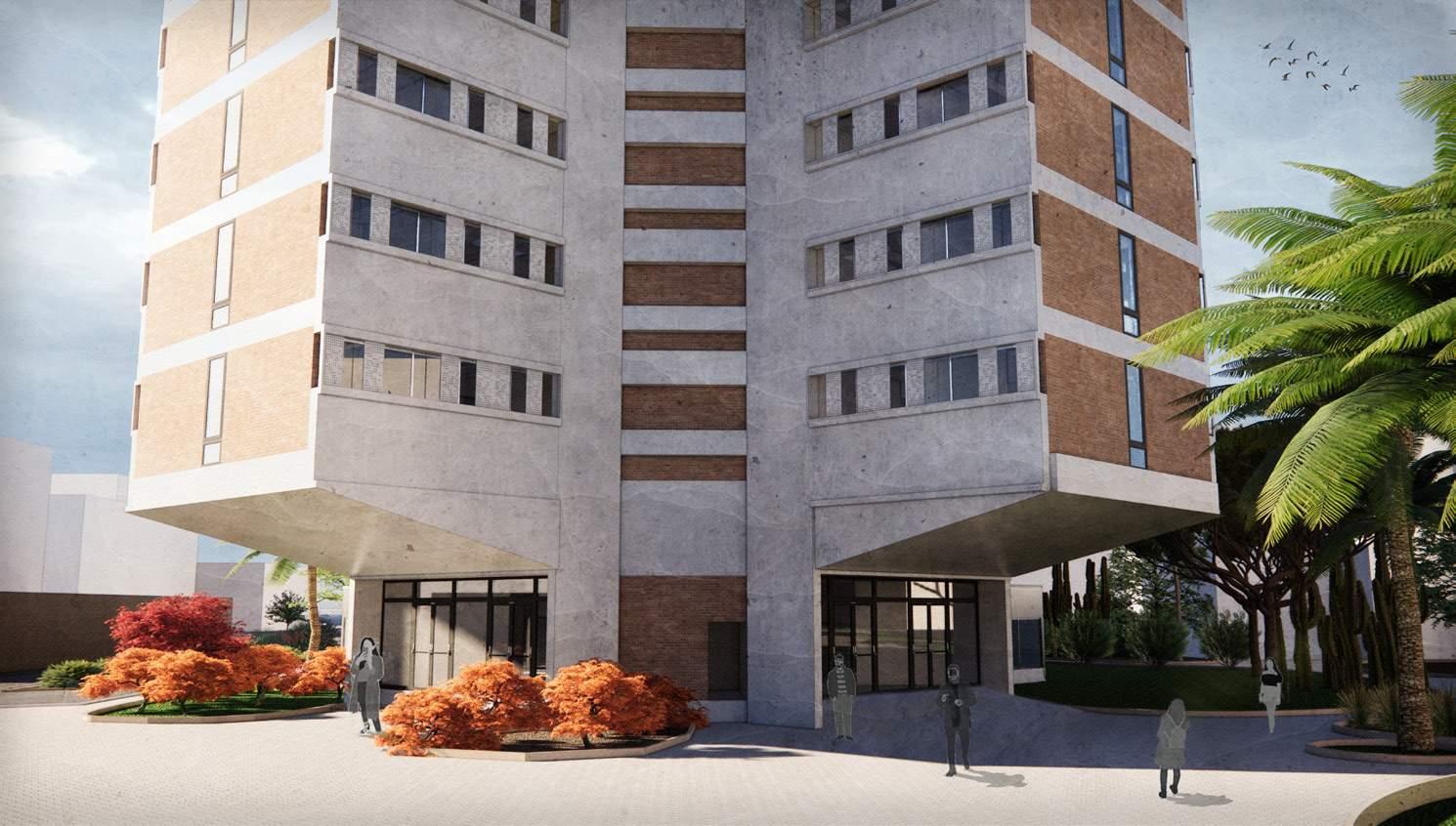
The views shows the entrance from the north west and north east direction.
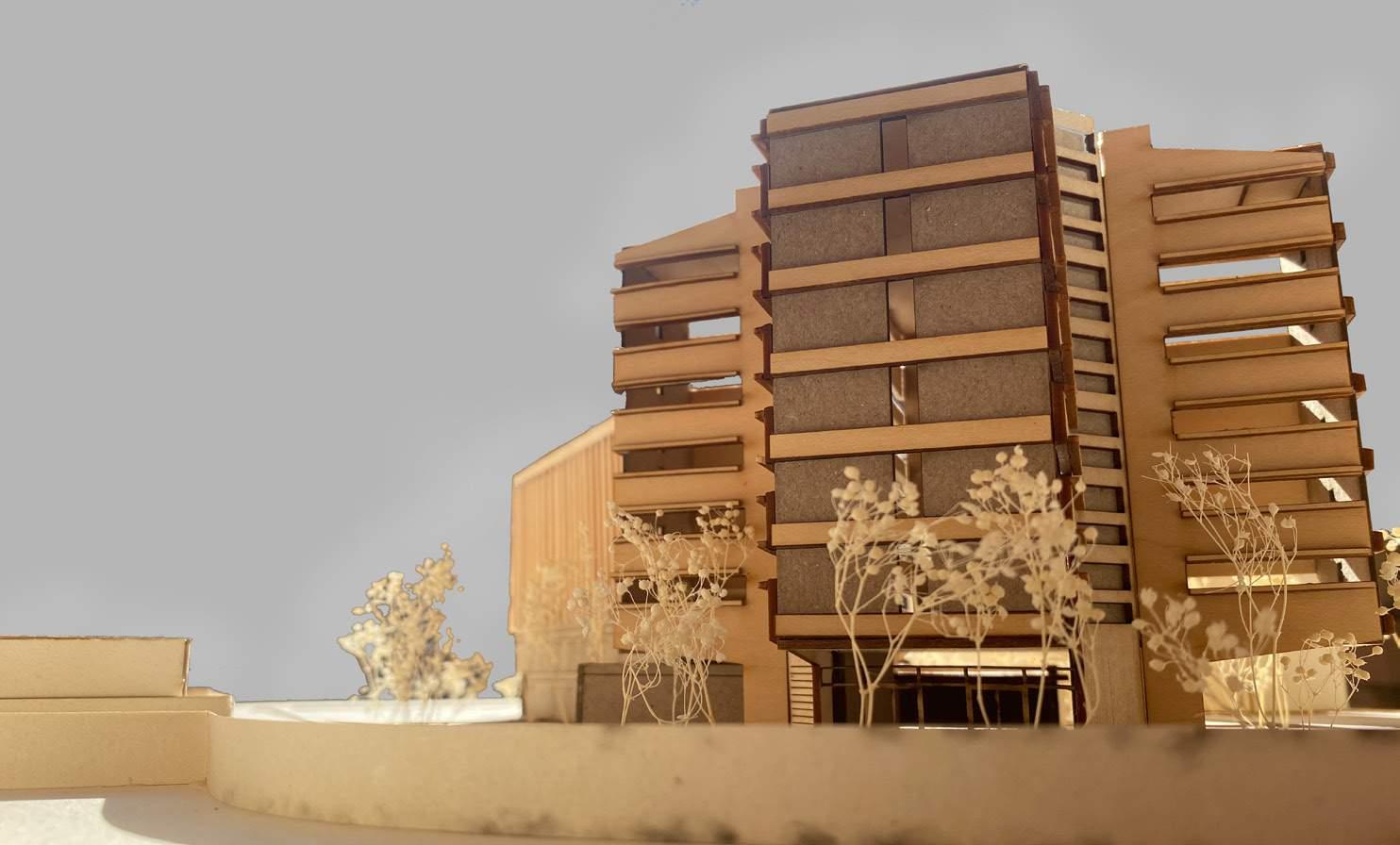
The louvers on the east and west responds to the winds and the direct sun rays reflecting on the glazed curtain walls. It is set on different
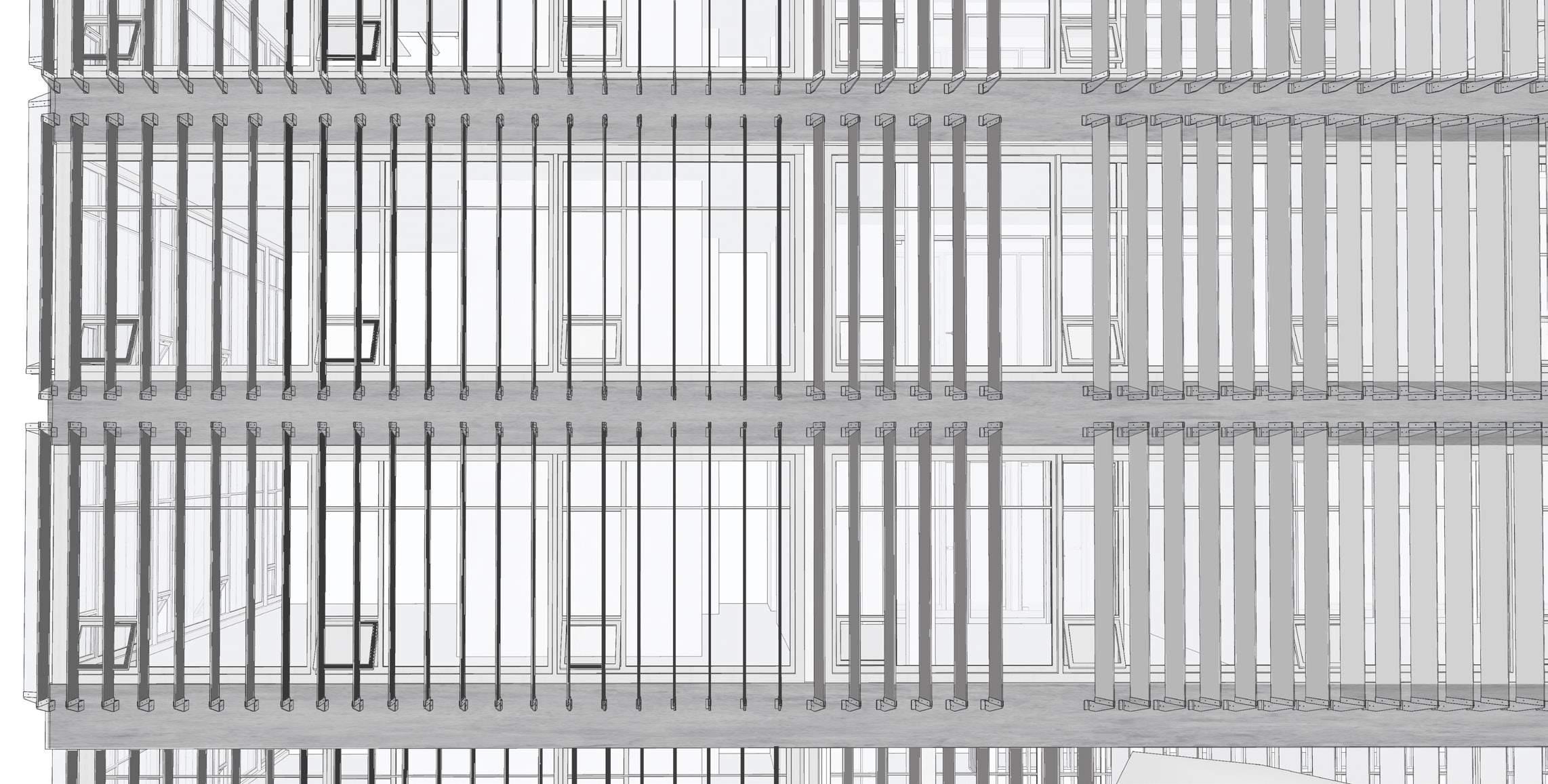
angles ranging from 90 degrees to 55 degrees in its orientation. All the louvers are connected through a metal clit worked out according to its
angles. The louvers are thought to be of aluminum to provide a light weight structure and those louvers are stuck to highlight the horizontal bands.
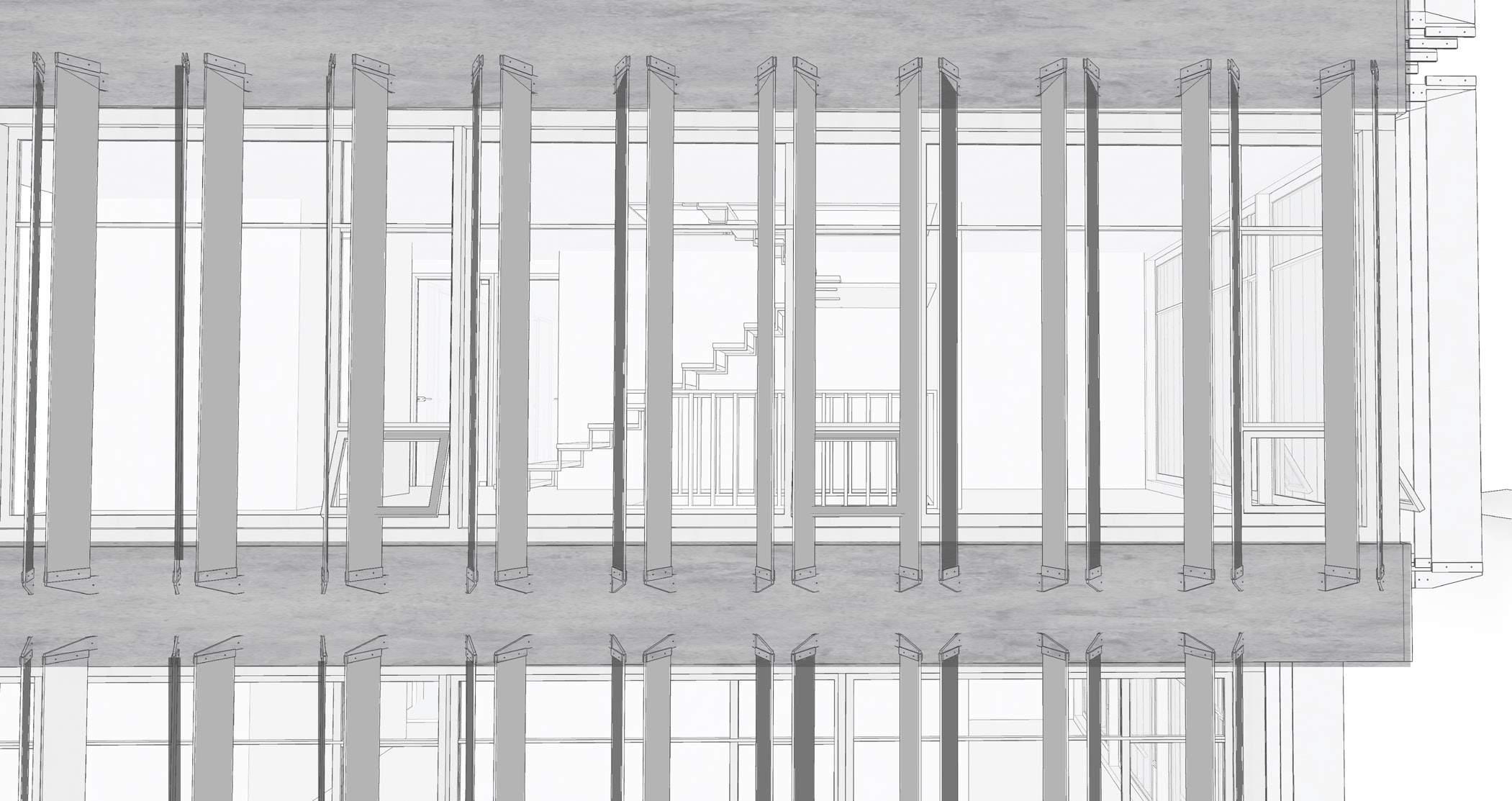
The louvers on the south are cas caded and allows to have maximum views. But the inclination is thought
of as a barrier and response to the X part of the building which provides the maximum shade in the narrow
parts of the position.
LIFT SHAFT
ANGLE CLITS FIXED VERTICALLY WITH THE SUPPORT OF BEAM + SLAB + FLASHING
GLASS CURTAIN WALL INSIDE TO PROVIDE THERMAL INSULATION BETWEEN LOUVERS AND THE CURTAIN WALL
FIXED ALUMINUM LOUVERS ON THE SOUTH DIRECTION FOR THE LIGHT BUT ALSO FOR PROTECTION FROM THE HARSH SUN
STAIRCASE KEEPING MORE VISIBLE ON THE NEWER ADDITION INCORPORATING MORE TRANSPARENCY TO SERVICE CORES
FLASHING FOR THE WEATHER PROTECTION OF THE BEAM AND SLAB STRUCTURE
I SECTION WITH SUSPENDED CEILING BELOW IT WITH T SECTIONS GRIDS
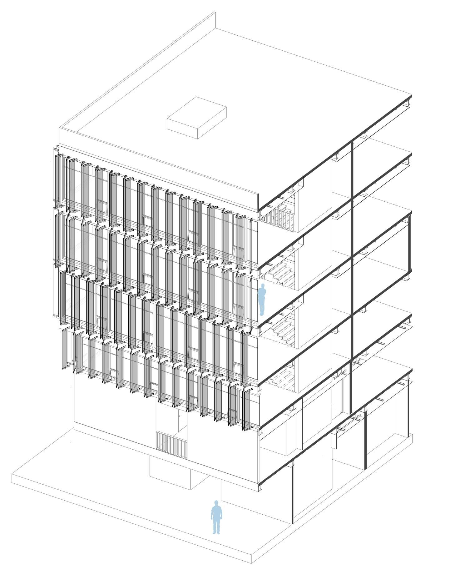
FLASHING FOR THE WEATHER PROTECTION OF THE BEAM AND SLAB STRUCTURE
INTERNAL WALLS WITH WOOD + GYPSUM
The view shows the expansion stacked along with the existing.
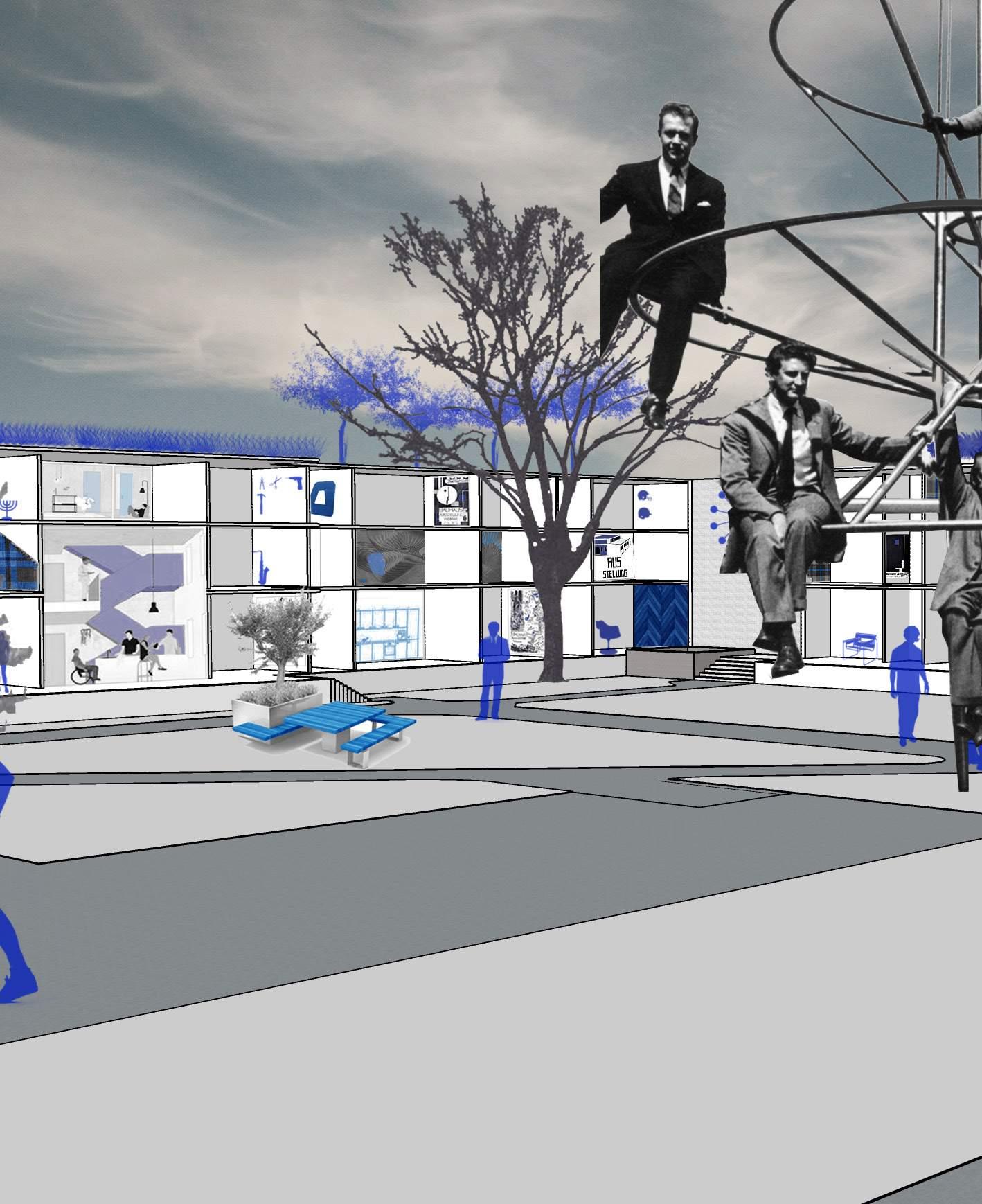
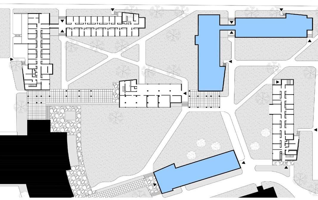
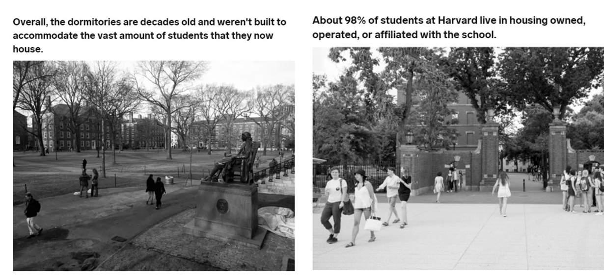
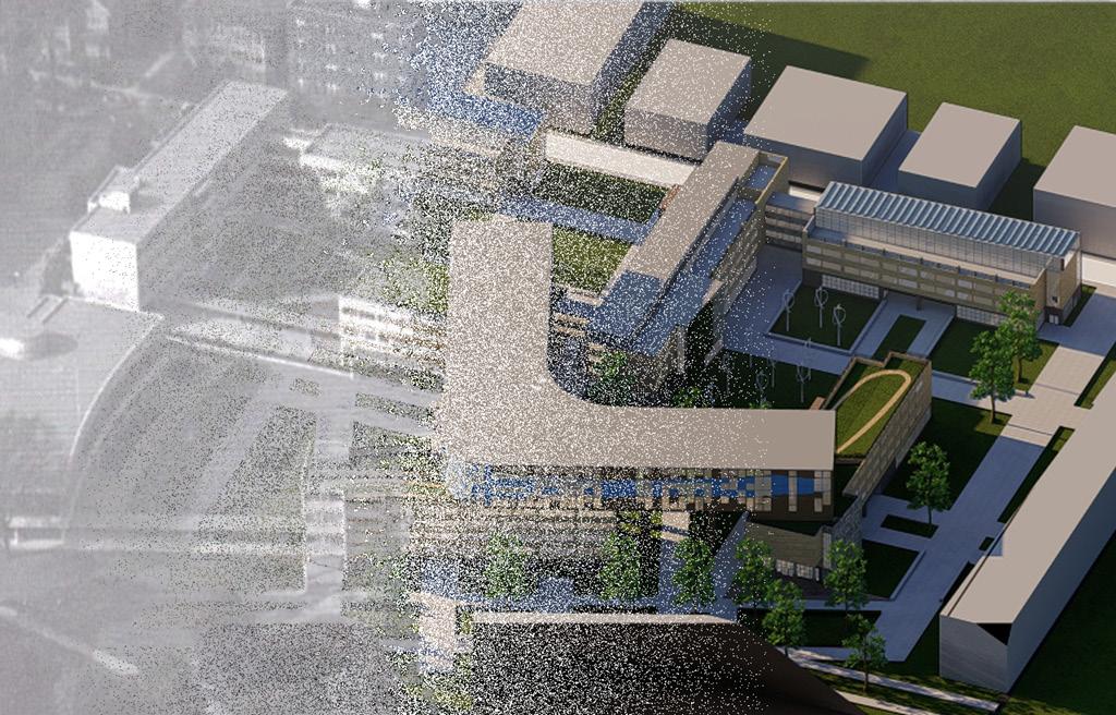
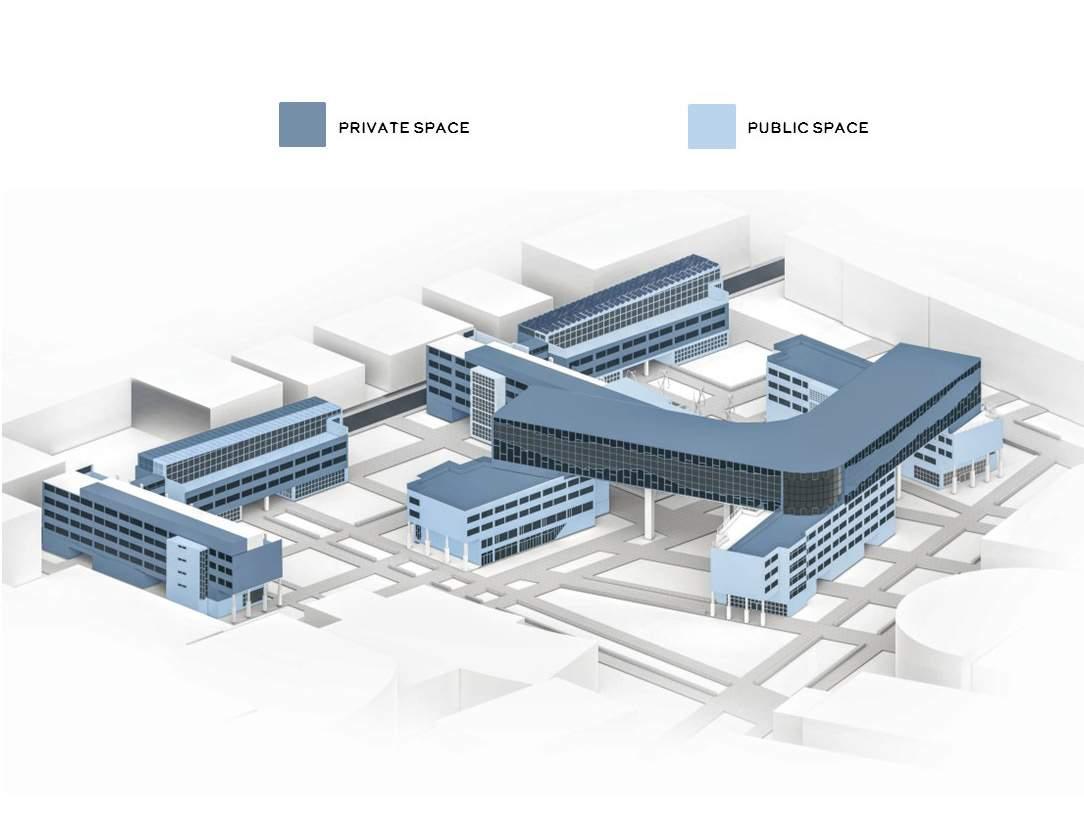
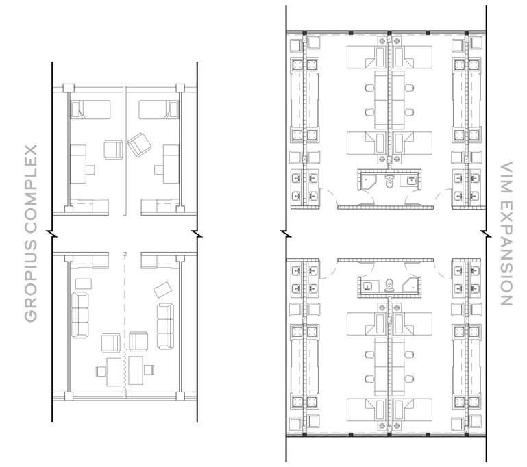
As 98% of Harvard students live in school-owned or affiliated properties within Harvard and Cambridge’s continued expansion, the Gropius Complex dormitories will be reinvented in the form of an adaptive reuse and urban renewal proposal, once again acting as a source of modernization and change for the University of Harvard. A new sense of community will be created through the implementation of state-of-the-art amenity and educational programs, establishing the students as chief constituents of the site, which was not the case before.
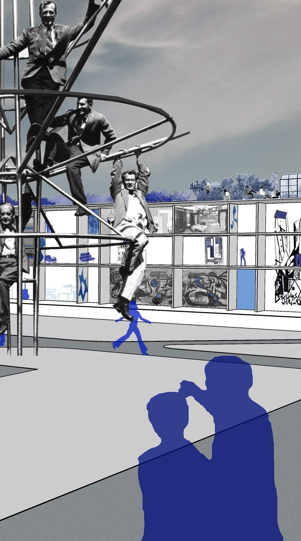
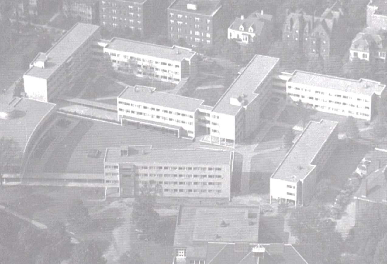
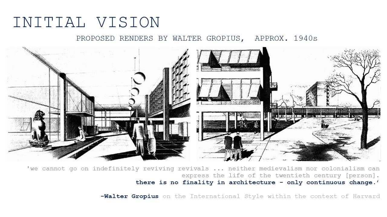
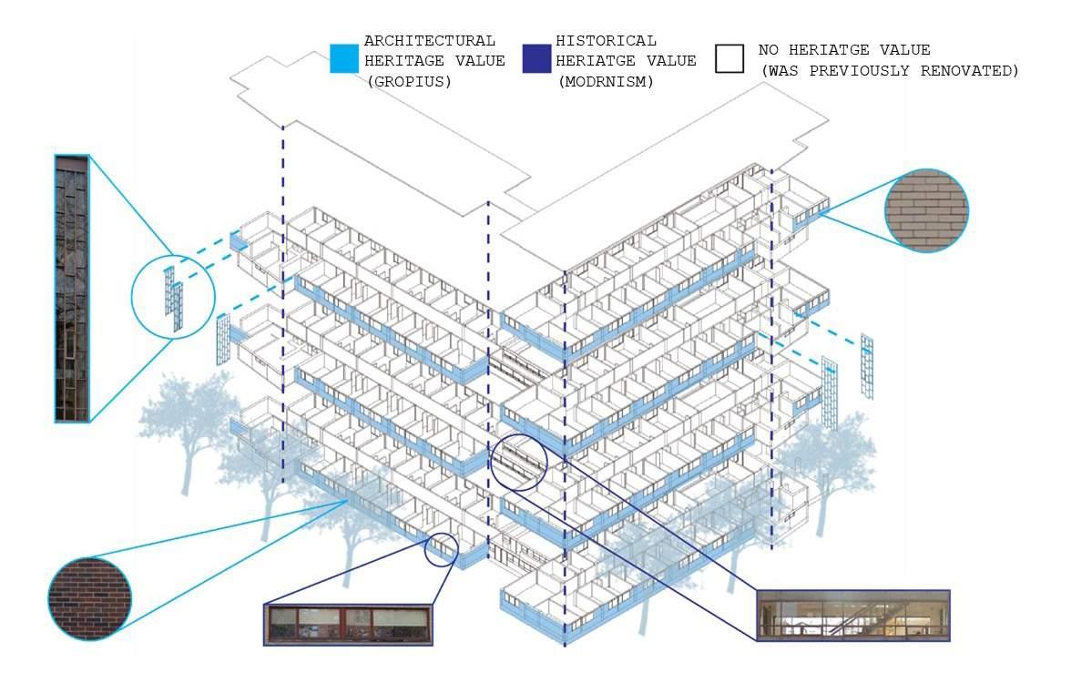
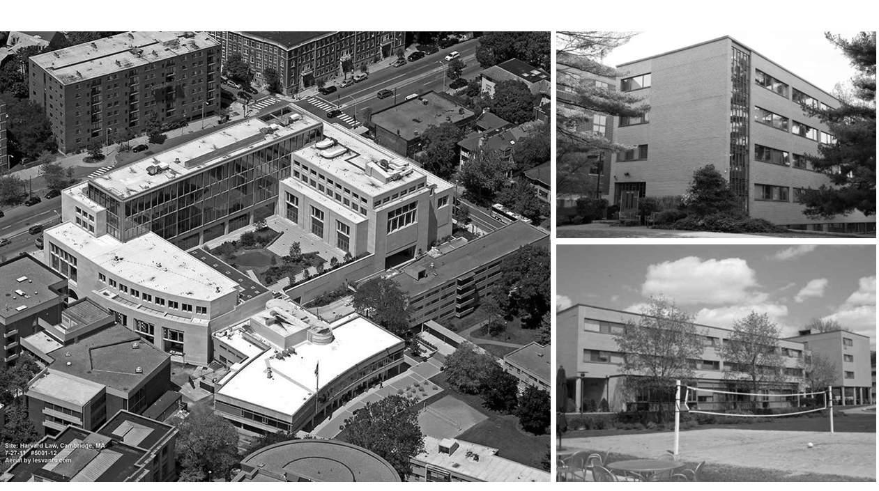
Harvard Graduate Center, nicknamed “The Gropius Complex” after designer Walter Gropius, was one of the most prominent showcases of the modernist doctrine within the United States.
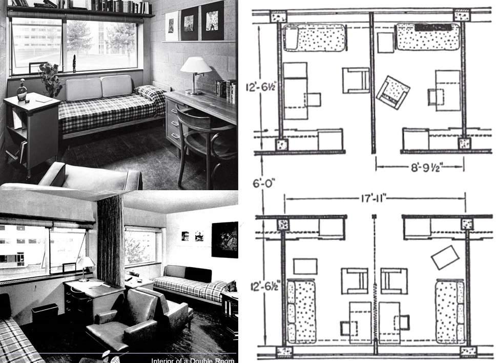
The small-sized rooms, decrepit conditions of the buildings, as well as lack of privacy for students have left most of the Gropius Complex (almost all 8 buildings) nearly unusable and closed to the public.

The proposed urban renewal and adaptive reuse will redefine the quality of life and identity of The Gropius Complex, modernizing the Harvard Law Campus to meet the needs of todays and tomorrow’s students while establishing a greater connection to the rest of the university.
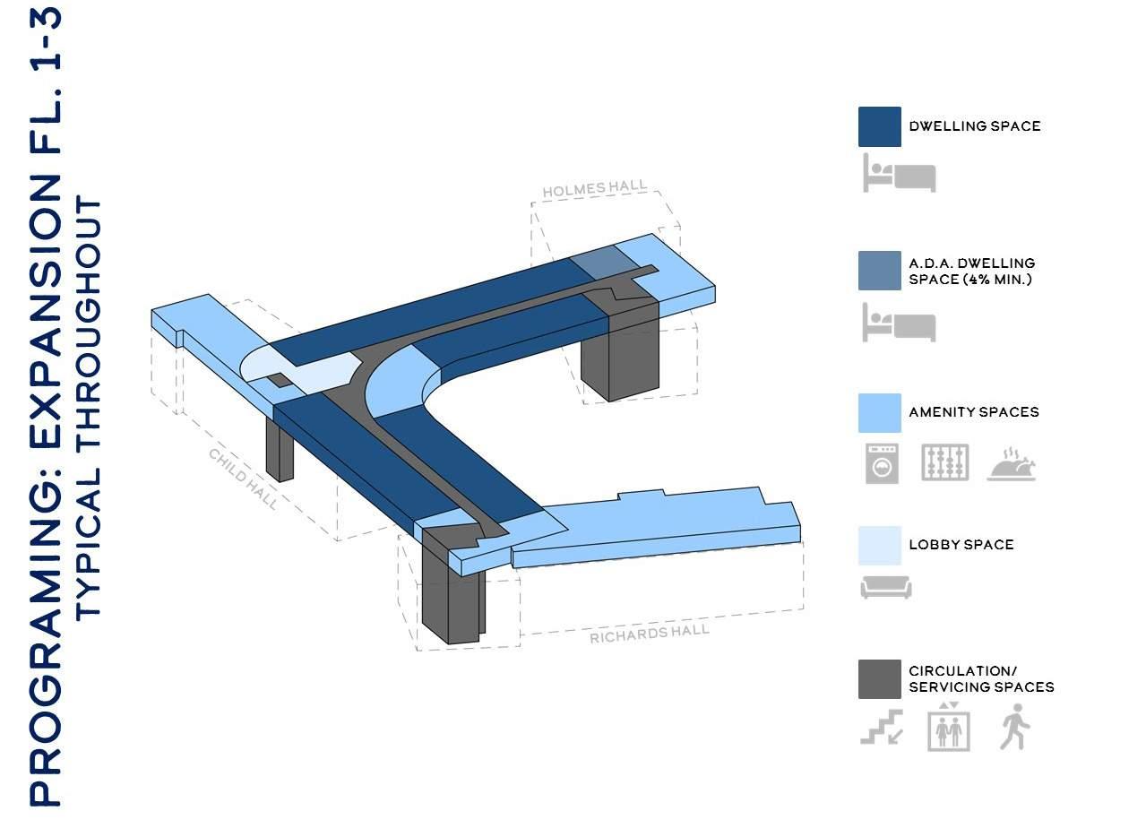
Story, Shaw, Holmes, Richards, Ames, Dane as well as Child Hall will be adapted to serve the current and future students and surrounding Harvard campus as a state-of-the-art residence complex and educational facility, while being universally accessible.
In 2012, Robert A.M. Stern Architect’s (RAMSA) completed an adaptive reuse project of the Caspersen Student Center (designed as part of the original Gropius Complex) and will not be included in our scope of work.
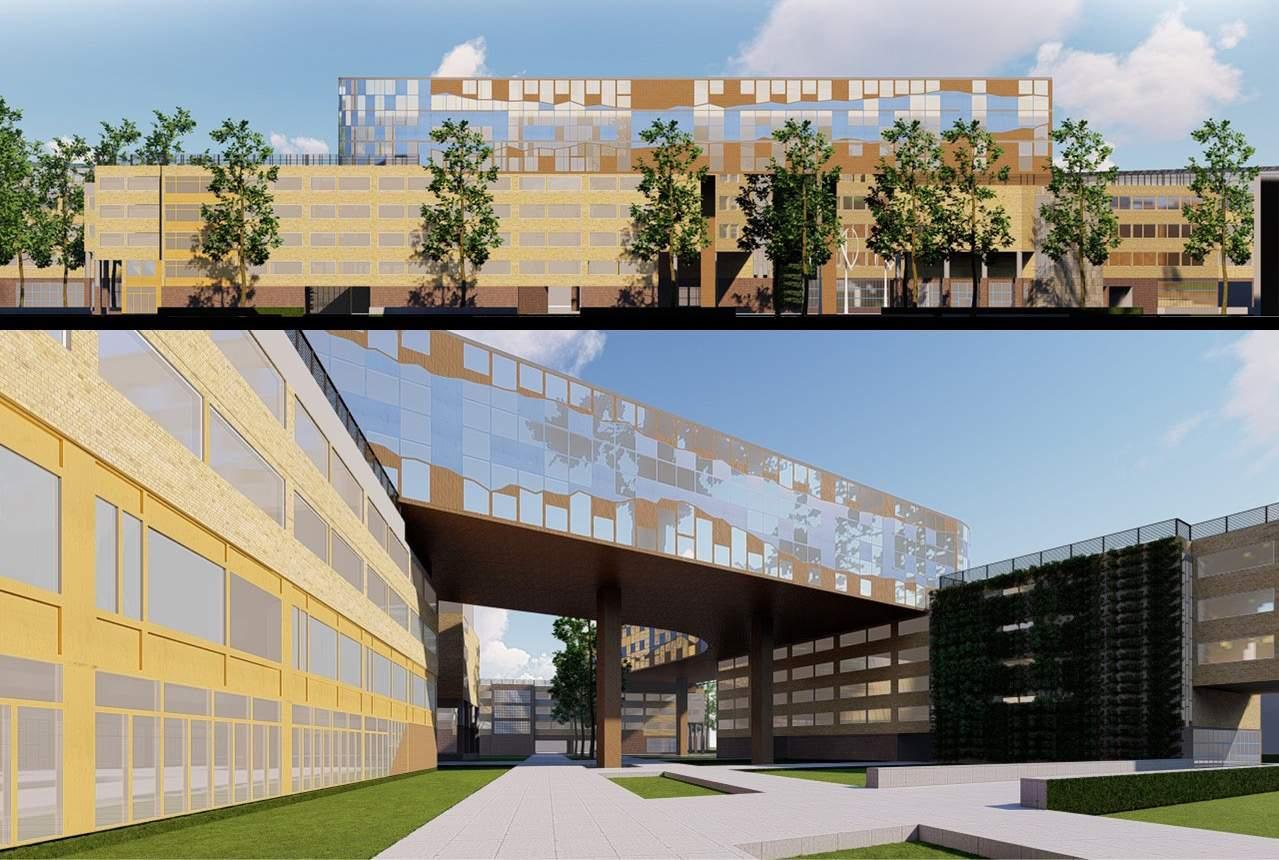
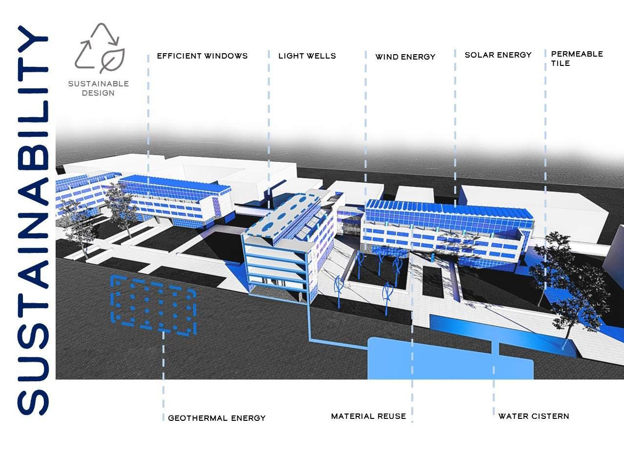
The proposed design will use modern construction methods and will contain sustainable features in order to further emphasize the ideological shift to stricter green practices within the site while respecting the deep, historic link between Walter Gropius, the international style, and Harvard University.
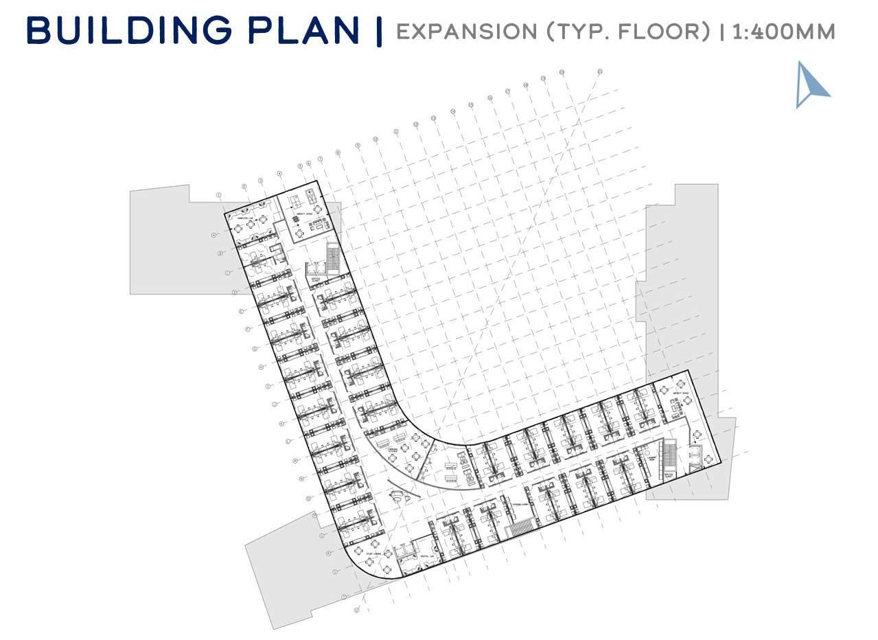
The new additions including the Child and Richard Hall educational facilities provide spacious room layouts, amenity spaces and an emphasis on sustainable practices.
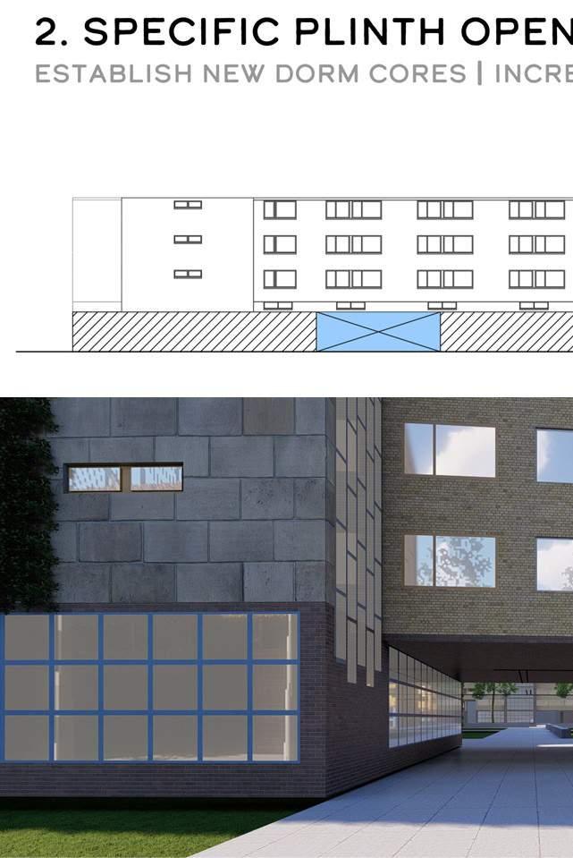
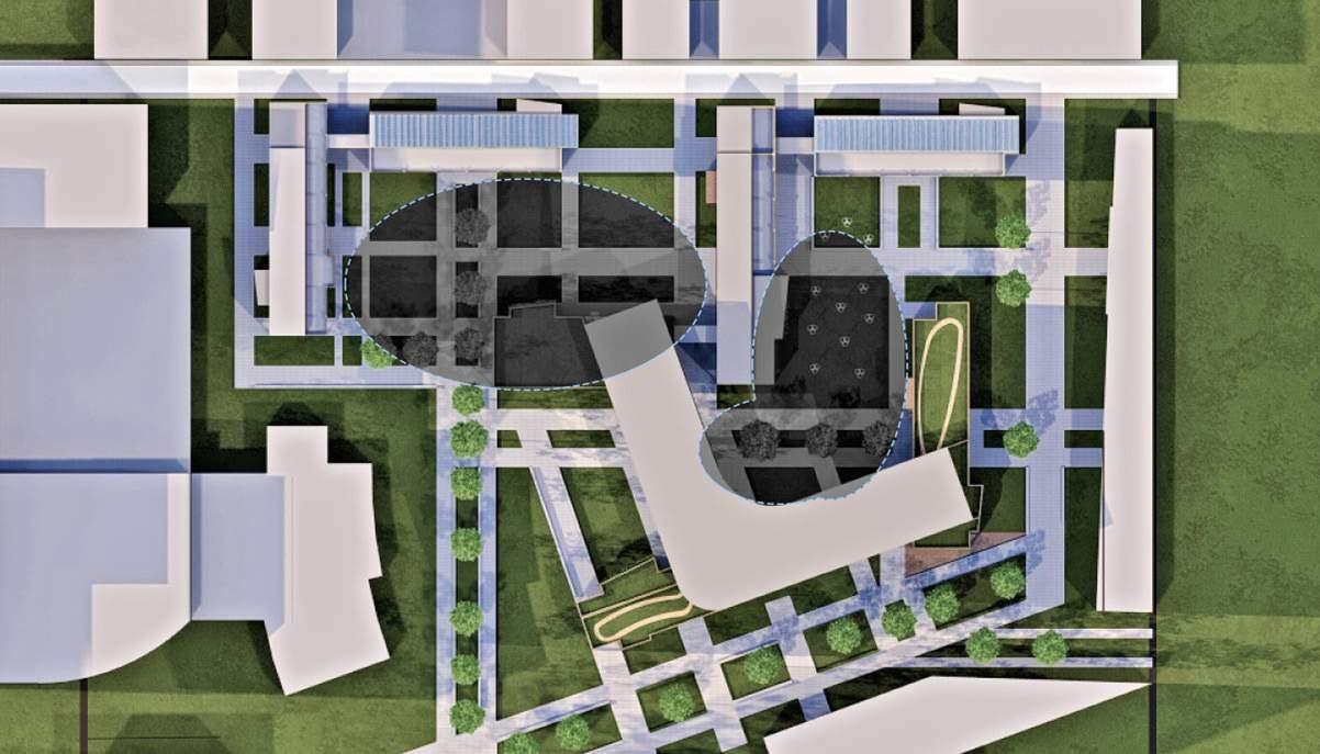
By establishing new entrances and access points to the site through the installation of plinths, the proposed adaptive reuse will bring life back to The Gropius Complex and provide better security, privacy and new opportunities for Harvard students and faculty.
Due to the fact that nearly the entire student population at Harvard Univeristy (98%) lives in schoolaffiliated housing and housing complexes, the need to expand and create more living spaces for current and future students is ever-present.
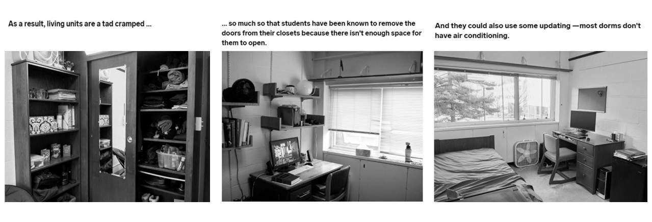
The Gropius Complex, often described as cramped, dark, and poorly maintained by past ocupants, currently holds only 35% of its original capacity. As Harvard expands and if the conditions of the units are not improved, the once prominant Gropius Complex will become a detriment to Harvard’s future, completely opposing the original intent of the design.
The need for sustainibility and green practises around the site is extremly important to today’s and tomorrow’s students. The new Gropius Complex will adapt to meet those needs and contribute to healthier living and learnign environment.
The need for private spaces and separation of space within the Gropius Complex is paramount for the successful future of this site. Due to numerous unfortunate incidents involving unwanted vistors and overwhelming amounts of touritsts
through the site, students have felt unsafe living within the Gropius Complex. These unfortunate events, often involving students, have forced the closure of almost all first floor units and living spaces. The new Gropius
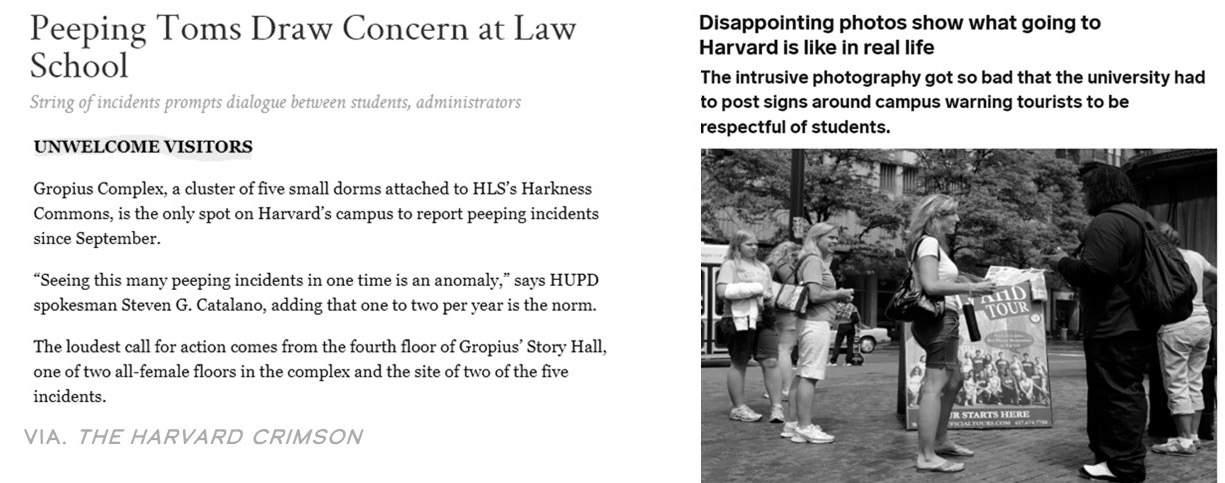
Complex seeks to address and improve site infrastructure to create a welcoming and safe environment for all.
Our team was inspired by the writing and new ideals for student living space design described by Tim McKeough and supported by
leading architects within the industry. The adaptive resue proposal for the Gropus Complex will use the site drivers outlined above in order to
shape the new identity of the site.
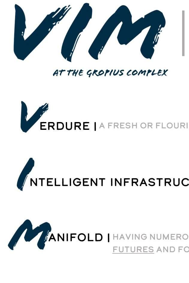
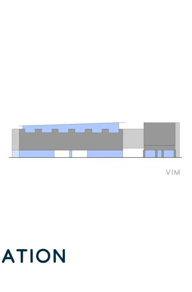
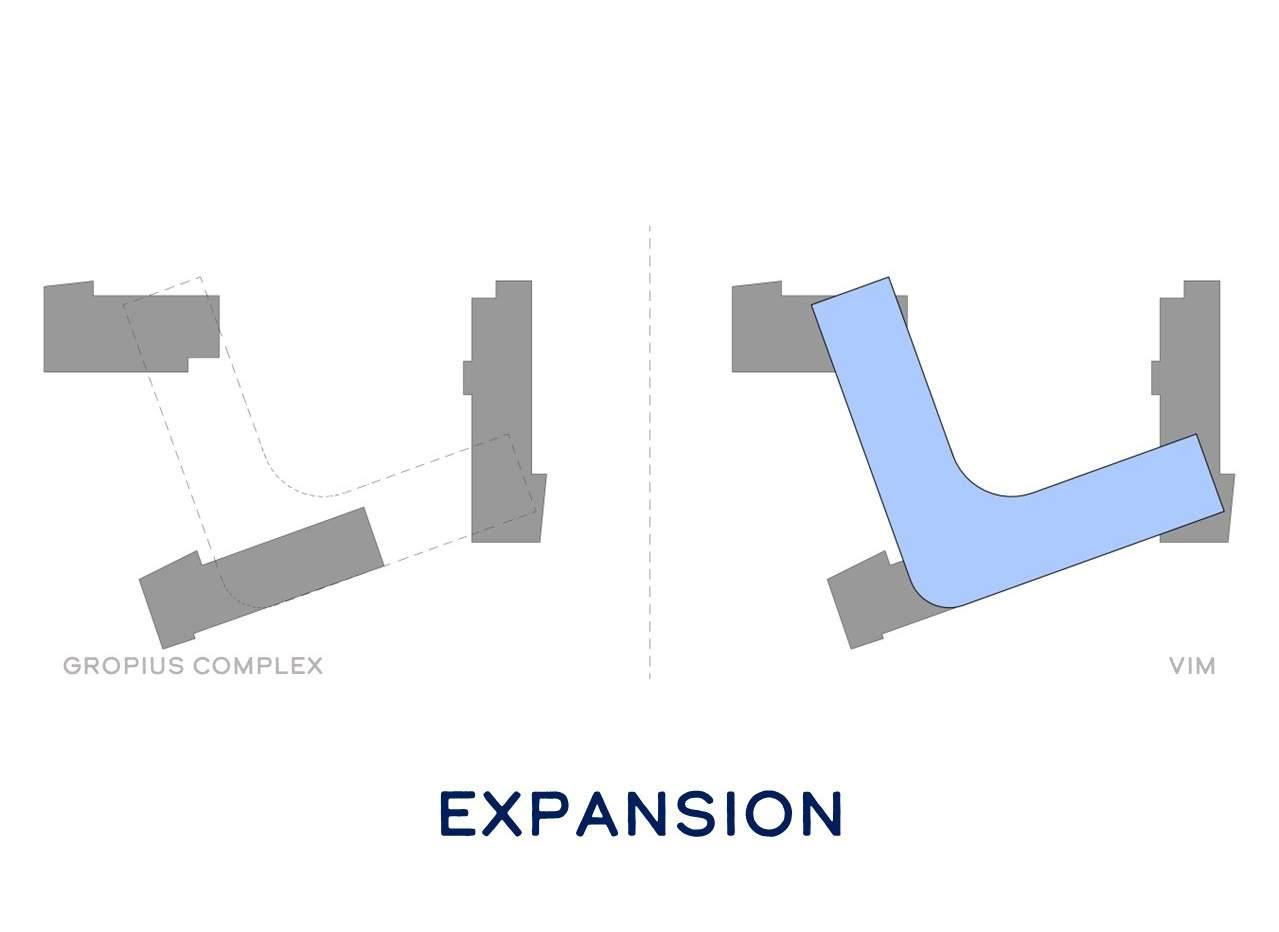
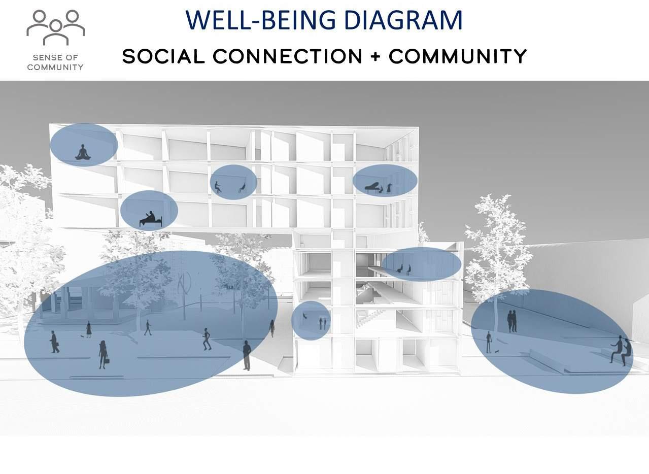
The new community will be complimented by contemporary sustainable practices throughout the site, designed to provide 100% comfort for occupants. In addition, a funtional architectural vernacular capable of providing spaces that act as catalysts for student learning and success will be used to give the Gropius Complex a new identity of youthfulness and excitement, a new VIM.
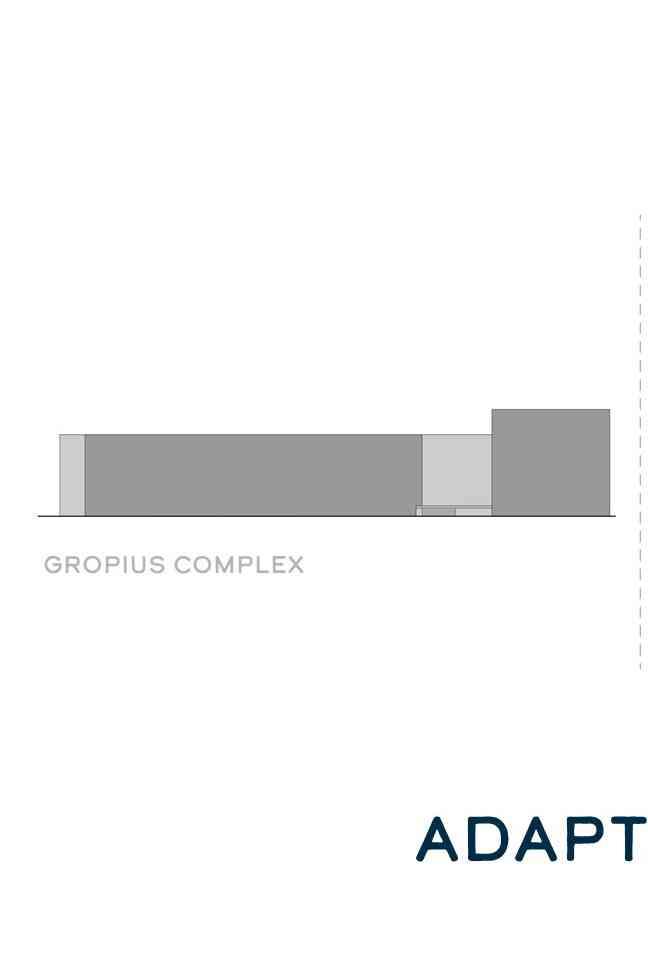
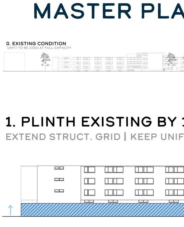
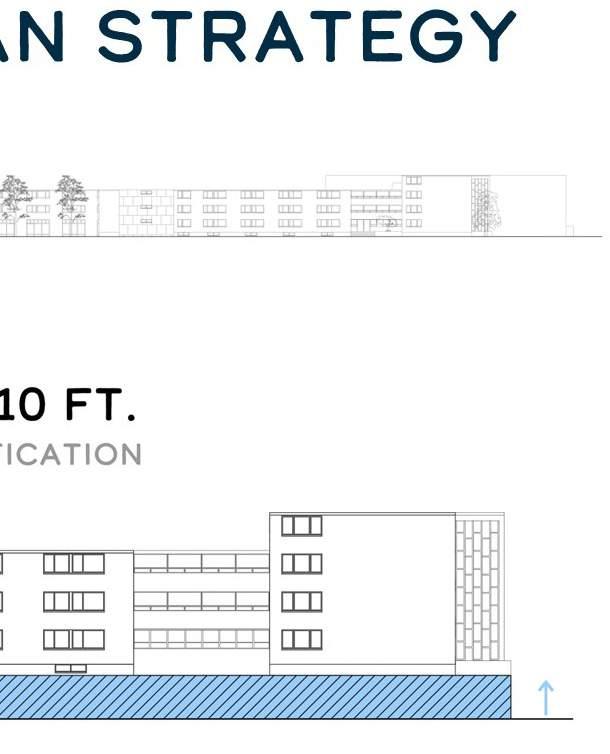
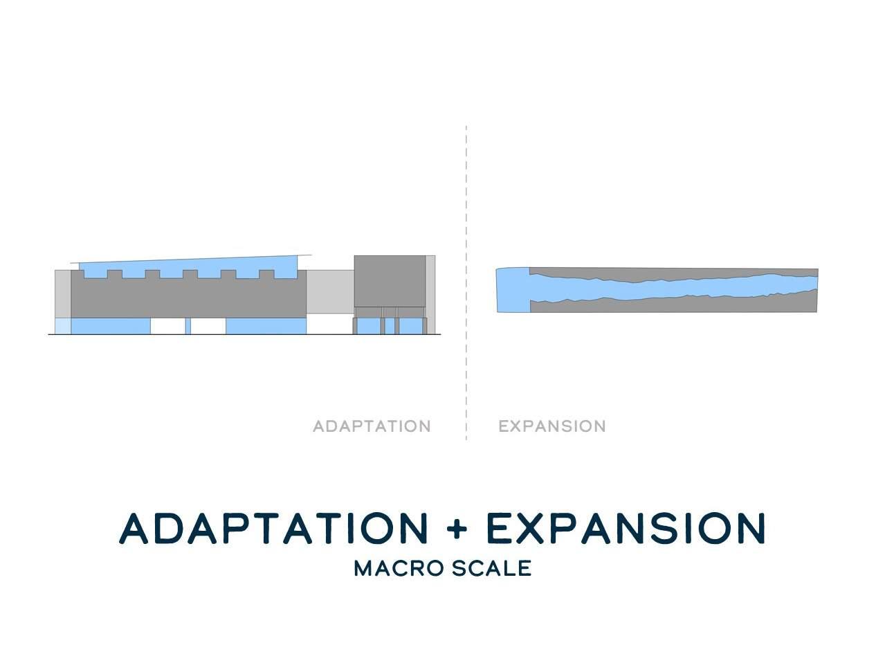
Our team as heavily inspired by the heritage conservation work by international architecture firm Herzog and De Meuron involving the “plinthing” of existing architecture. This is seen in standalone building projects such as the CaixaForum and the Elbphilharmonie in Hamburg. Our team will expand this apporach, implementing the plinth adaptation within each structure of the Gropius Complex.
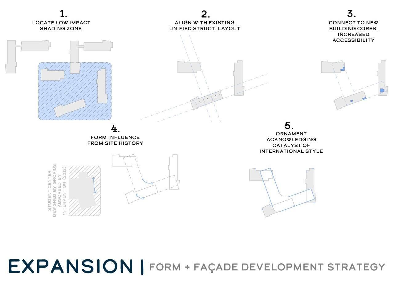
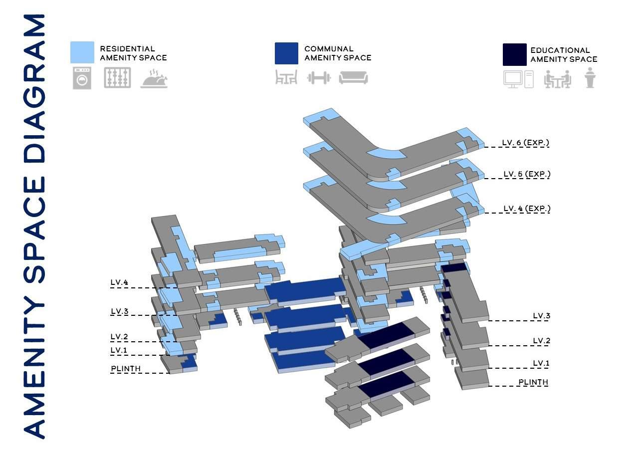
As a result of the plinthed structures across the site, new spatial opportunties for amenitiy, educational and coummunal spaces will be available in order to enhance student living and learning experiences. In addition, a three-storey expansion, taking inspiration from the contextual and historical forces of the site and surrounding area will be installed on the roof of Holmes, Child and Richards Halls, increasing site density and the strong demand for housing within Harvard’s community.

Allen, Edward, and Iano, Joseph. The Architect’s Studio Companion: Rules of Thumb for Preliminary Design. New York: John Wiley & Sons, Incorporated, 2017. Accessed November 28, 2022. ProQuest Ebook Central.
Berdini, Paolo. Walter Gropius. 2nd ed. Barcelona: G. Gili, 1996.
Chen, Stephen. “Here’s What It Was Like To Go To Harvard Law.” Business Insider. Quora, October 4, 2013. https:// www.businessinsider.com/heres-what-it-was-like-to-go-to-harvard-law-2013-10.
The Cooper Gallery. “The Gallery.” The Cooper Gallery. Harvard University, December 8, 2014. http://coopergalleryhc. org/about/the-gallery/.
Daybelge, Leyla, Magnus Englund, and Walter Gropius. Walter Gropius: An Illustrated Biography. London, U.K.: Phaidon Press Limited, 2022.
“Disappointing Photos Show What Going to Harvard Is like in Real Life.” Business Insider India. Business Insider, October 20, 2018. https://www.businessinsider.in/slideshows/miscellaneous/disappointing-photos-showwhat-going-to-harvard-is-like-in-real-life/slidelist/66294256.cms.
Etherington, Rose. “CaixaForum Madrid by Herzog & De Meuron.” Dezeen. Dezeen, May 22, 2008. https://www. dezeen.com/2008/05/22/caixaforum-madrid-by-herzog-de-meuron/.
Fitch, James Marston. Walter Gropius. New York City, NY: Braziller, 1960.
Frearson, Amy. “Elbphilharmonie by Herzog & De Meuron.” Dezeen. Dezeen, October 10, 2011. https://www.dezeen. com/2011/10/10/elbphilharmonie-by-herzog-de-meuron-2/.
Genia, Erin. “Selected Works.” Artwork. Cambridge, 2019. https://www.eringenia.studio/gallery.html.
Gianni, Ben. ARCS 4105: Housing, Community, City Building and Placemaking (Rules of Thumb for Residential Design, Carleton University, Ottawa, Ontario, September 11, 2021)
Gianni, Ben. ARCS 4105: Housing, Community, City Building and Placemaking (Misc. Construction Images, Carleton University, Ottawa, Ontario, November 26, 2021)
Gianni, Ben. ARCS 4105: Housing, Community, City Building and Placemaking (Phase 3: Digital Constructional Model, Carleton University, Ottawa, Ontario, November 26, 2021)
Historic New England. Gropius House: Lincoln, Massachusetts. Historic New England, 2011.
Isaacs, Reginald R. Gropius: An Illustrated Biography of the Creator of the Bauhaus. 3rd ed. Boston, MA: Little, Brown, and Company, 1991.
Krohn, Carsten. Walter Gropius: Buildings and Projects. Basel, Switzerland: Birkhauser Verlag, 2019.
Lupfer, Gilbert, and Paul Sigel. Walter Gropius, 1883-1969: The Promoter of a New Form. Los Angeles, CA: Taschen, 2004.
McKeough, Tim. “How Architects Are Innovating the College Dorm.” Architectural Digest. Architectural Digest, August 13, 2018. https://www.architecturaldigest.com/story/college-dorm-architecture-emerson-studio-gangelkus-manfredi.
McLean, Elizabeth. ARC 501: Advanced Architectural Studio I (Module III Notes, Arizona State University, Tempe, Arizona, United States of America, October 5, 2022)
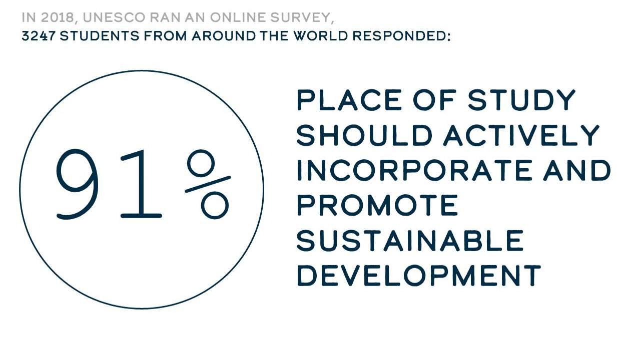
UNESCO. “Most Students Want Sustainable Development as Part of All University Courses, Survey Reveals.” UNESCO.org. UNESCO, April 21, 2022. https://www.unesco.org/en/articles/most-students-want-sustainabledevelopment-part-all-university-courses-survey-reveals.
Yee, April H.N. “Peeping Toms Draw Concern at Law School: String of Incidents Prompts Dialogue between Students, Administrators.” The Harvard Crimson. February 25, 2005. https://www.thecrimson.com/article/2005/2/25/ peeping-toms-draw-concern-at-law/.
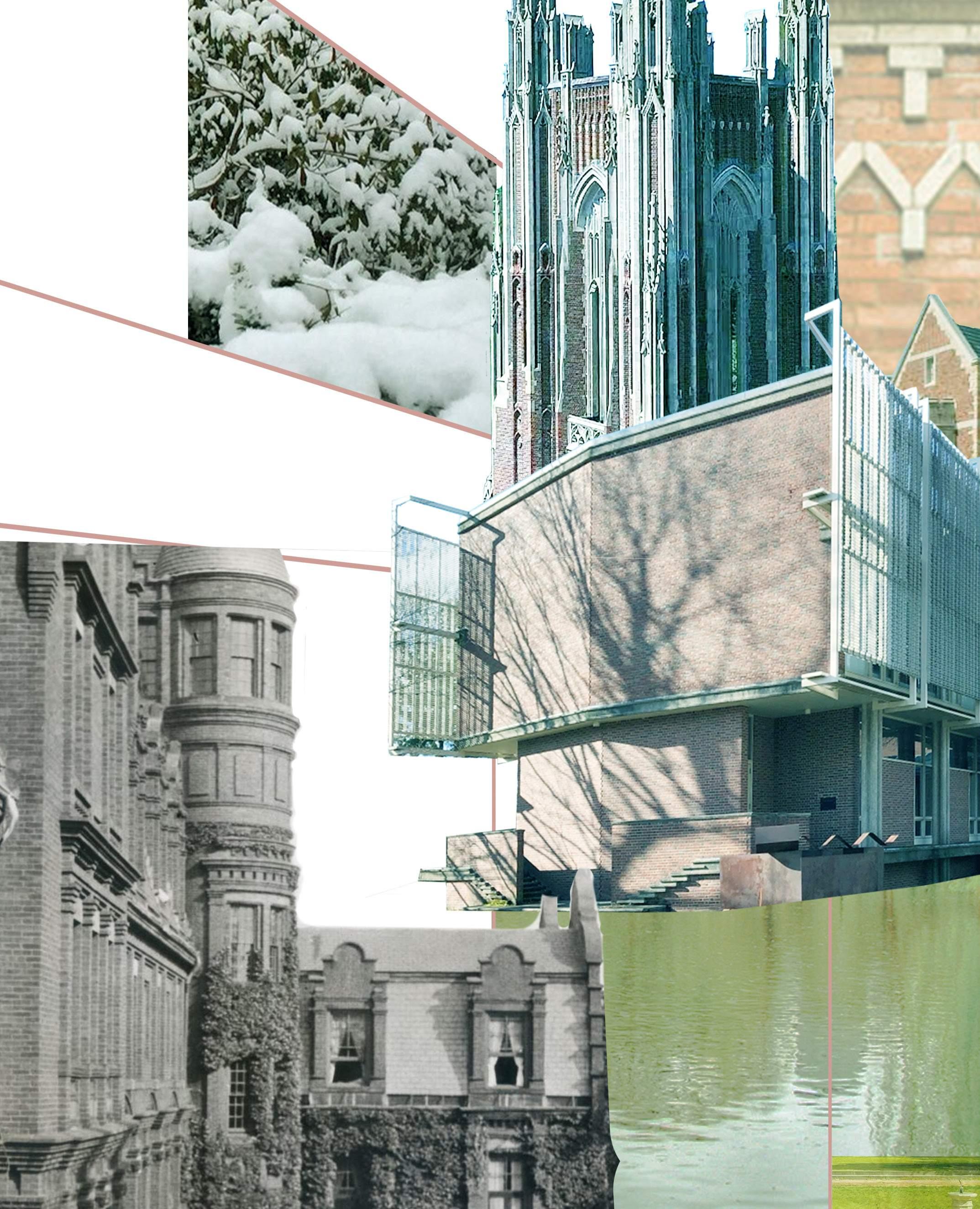
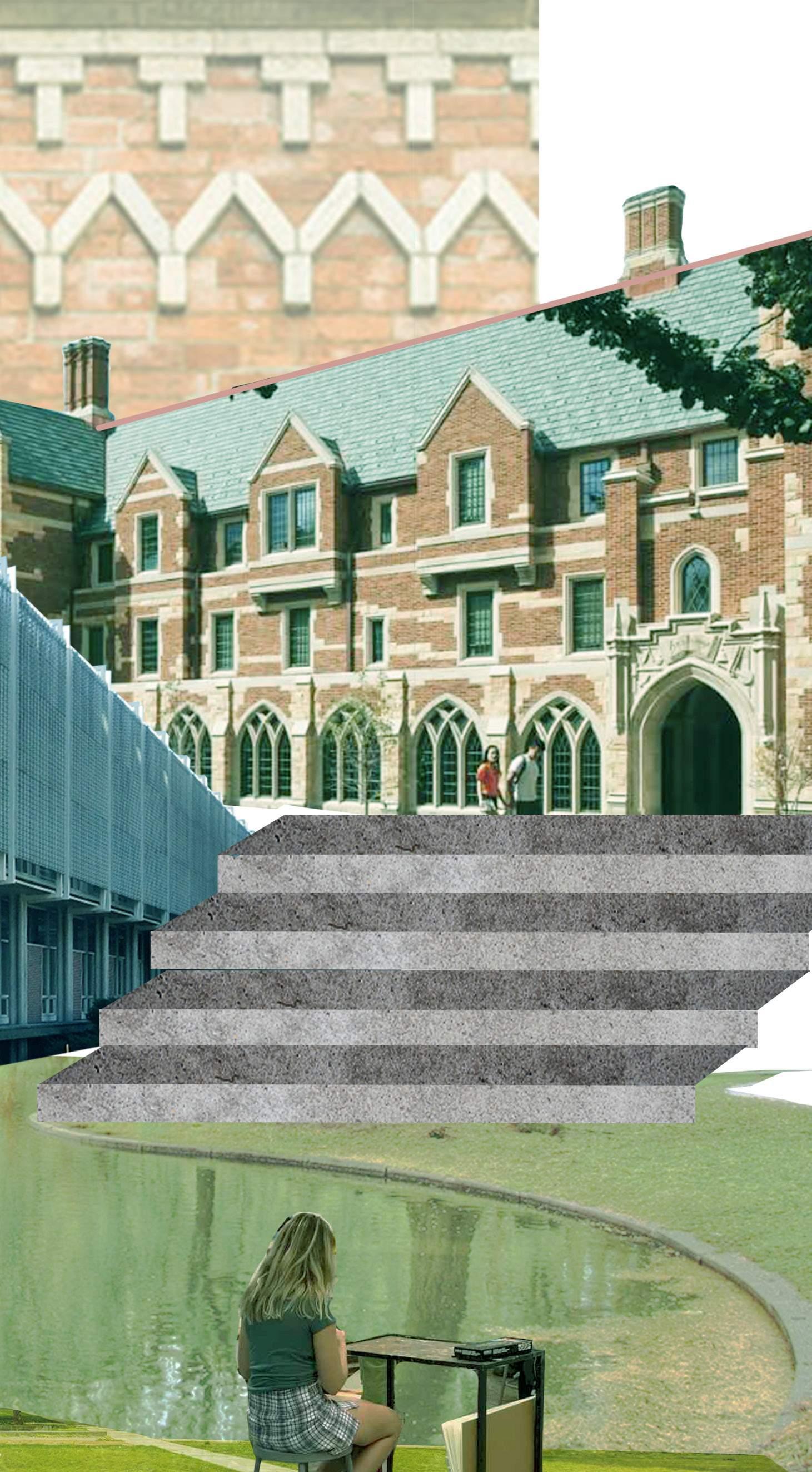
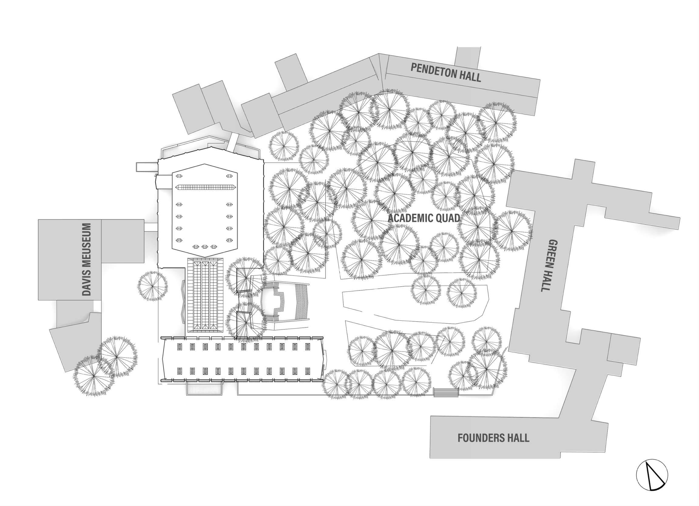
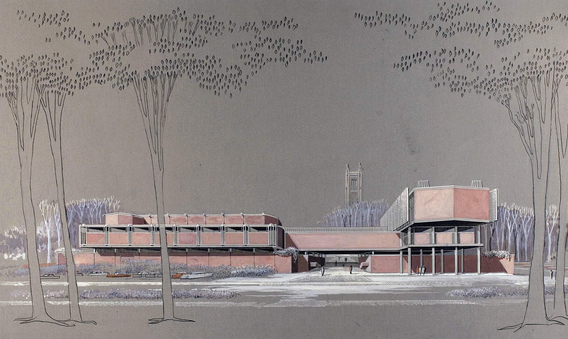
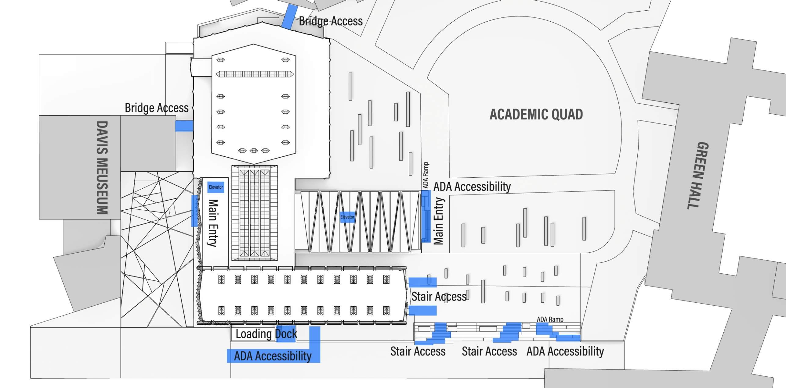
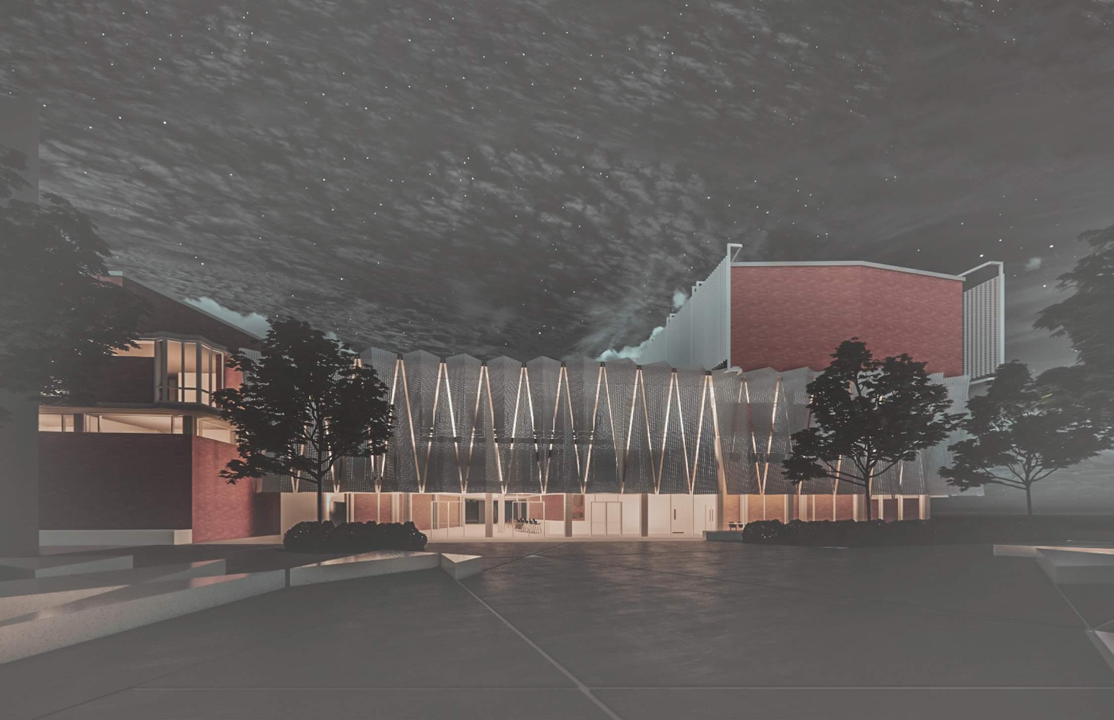
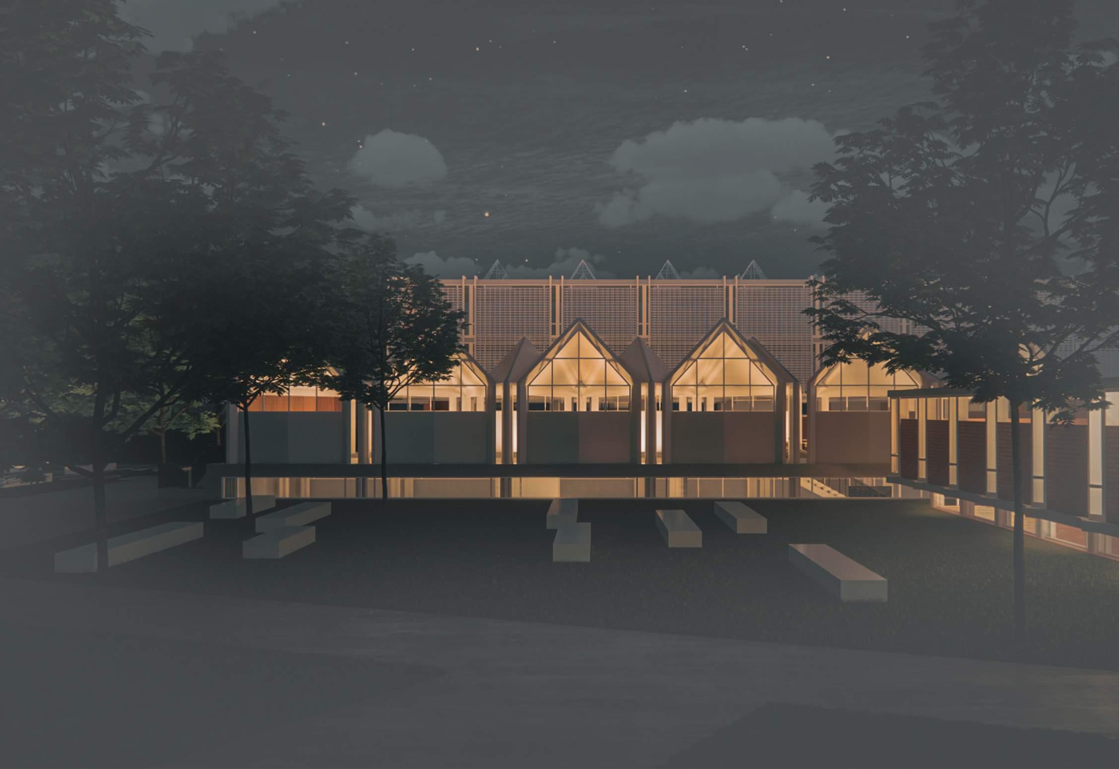
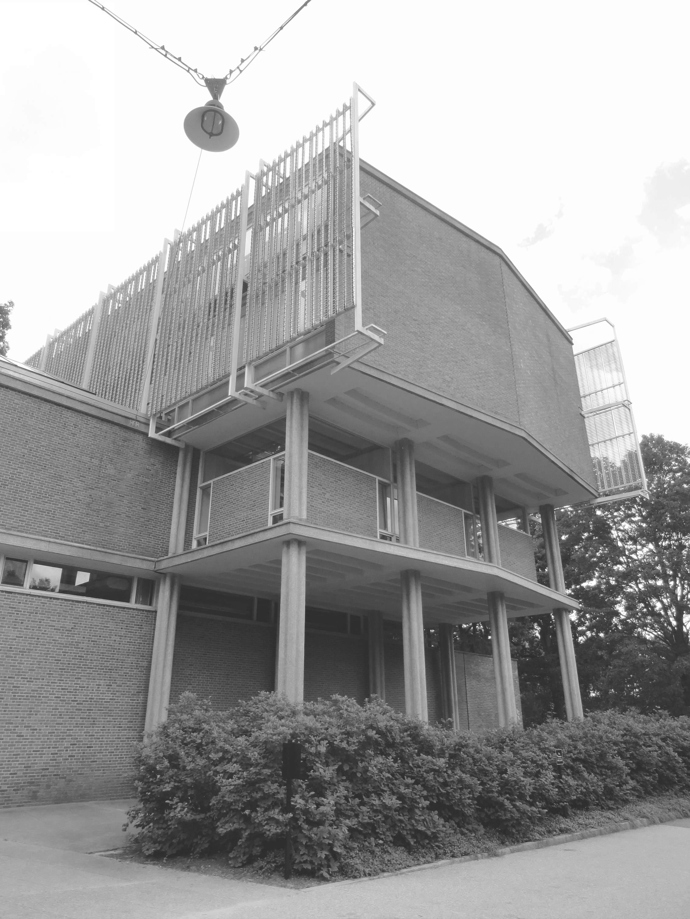
This study focuses on the Mary Cooper Jewett Art Center at Wellesley College located in Wellesley, Massachusetts. The architecture is designed by the famous Modernist Architect Paul Rudolph. It contains a Music Hall, Art Studio, Gallery, Library, office, and many other educational programs. The challenging part of this design is that the building is surrounded by Neogothic-style architecture. the request is to design a modern architecture that also needs to blend with the existing environment.
Paul Rudolph used red brick same as the existing architecture but also applied horizontal concrete forms to design modern architecture. The pointed glass roof window also represented the Neo-Gothic style and let this modern style of architecture blend in with the surroundings. Over the Years the Jewett Art Center has been renovated many times to update the different programs’ uses and current technologies. This study focuses on identifying the architecture’s current limitations and provides improvement.


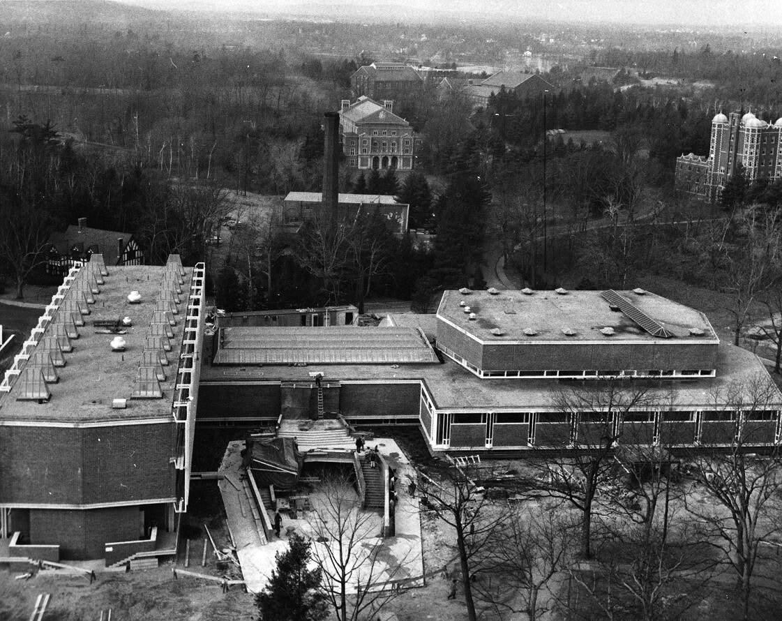
The program for the Jewett Arts Center was under consideration for many years. By the end of World War II, Wellesley College had grown physically and intellectually to such an extent that the galleries, storage areas, study rooms, and other facilities for the arts had become obsolete and inadequate. Moreover, classrooms, studios, exhibition spaces, and performance spaces needed for teaching the history of art and studio art, music, and theater were scattered
across campus, reflecting the College’s commitment to these subjects but undermining the ability to offer the sort of comprehensive. Dempsey insisted that the College build a modern structure, one of high-quality design, and one where the architect would be given as much free rein as possible in matters of design. Jewett Arts Center: we force art down the optic nerves not only of our own students but also those of Music and Drama,—at least we plan to when
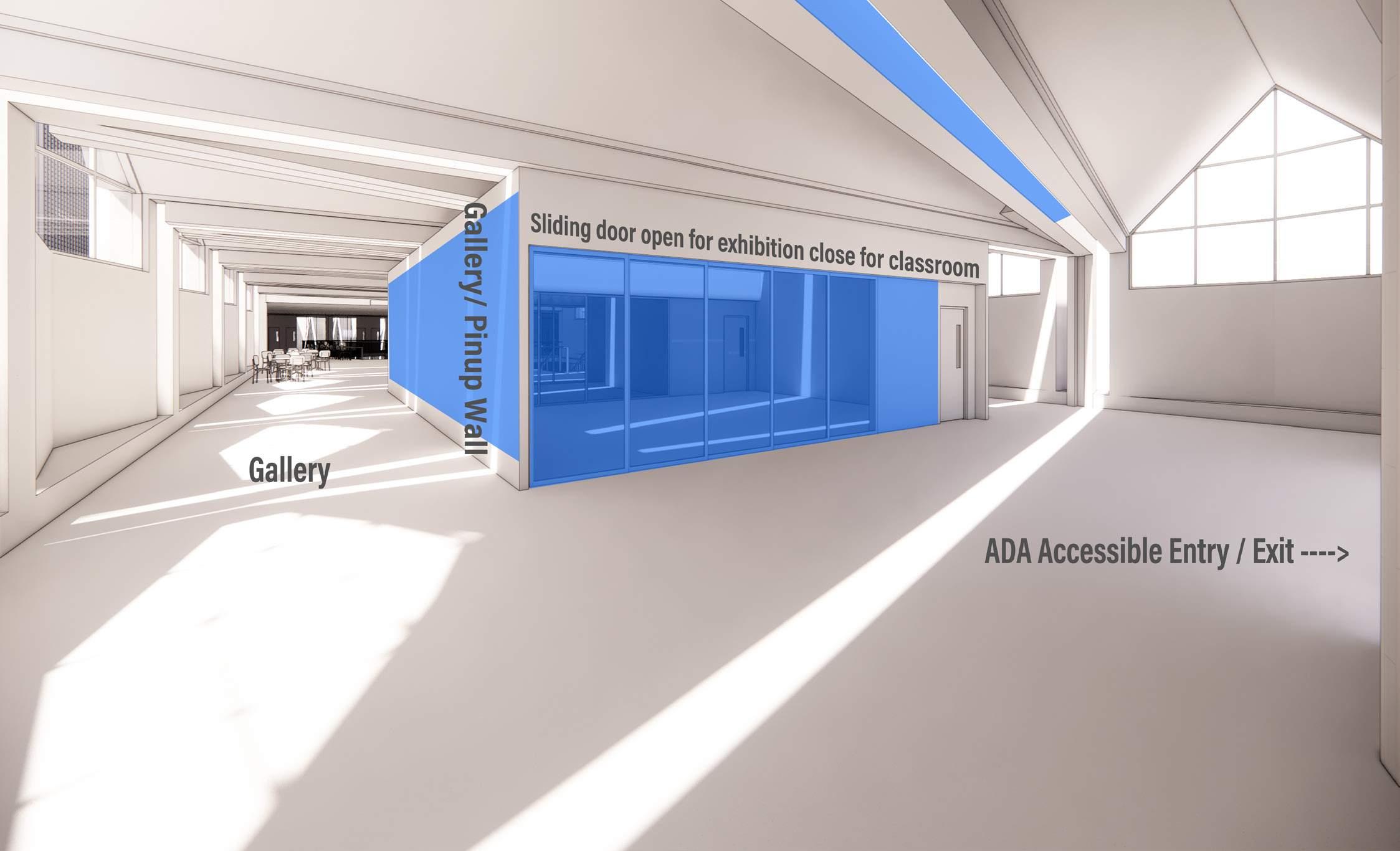
enough of the building is done. The main place for this is the main gallery, strategically set right in the middle of the Center. Whether bound towards Art, Music, or Drama, everyone who enters the building must go through some part of the gallery, either the corridor for drawings, prints, and watercolors...or the main gallery itself.
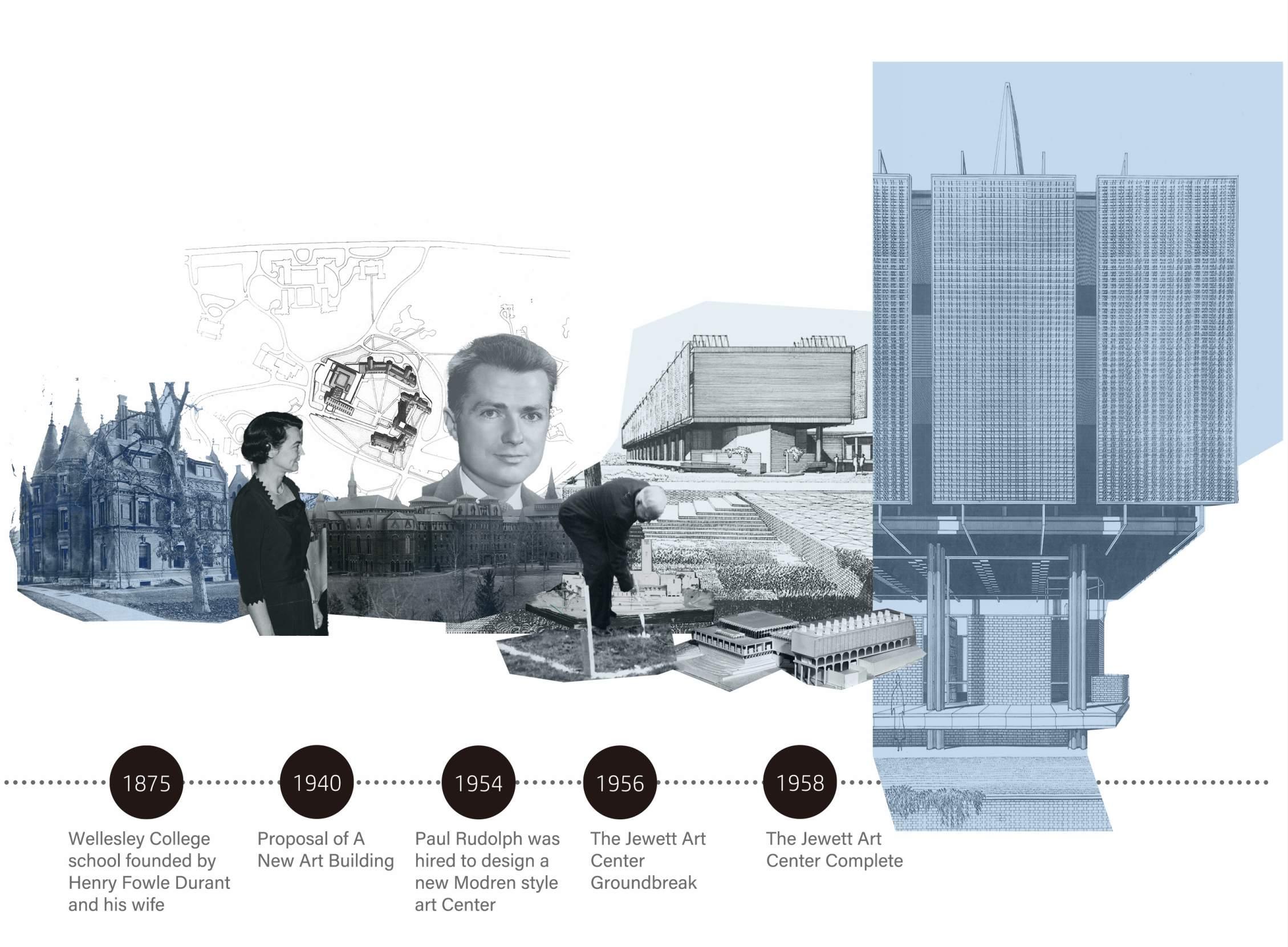
Wellesley collegeis a private women’s liberal arts college located in suburban of Wellesley, MA. Within its expanse lies residence hall, libraries, classrooms and laboratories, studios, cinema and Th eaters, Cafes and Dining Halls, Art Falleries, office, a golf Courseand more
Founded: Founder: Campus: Ranking: Education: Population:

1870 Henry Fowle Daurant 500 Arc
#5 National Liberal Arts Baccalaureate 2383 Students 1224 Teachers 1:8 T&S Ratio
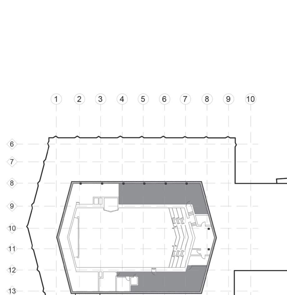
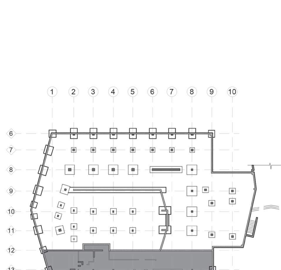
Third Floor
1 2 3 4 5 6 7 8 9 10
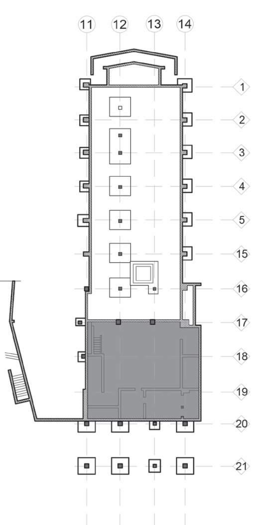
Fourth Floor
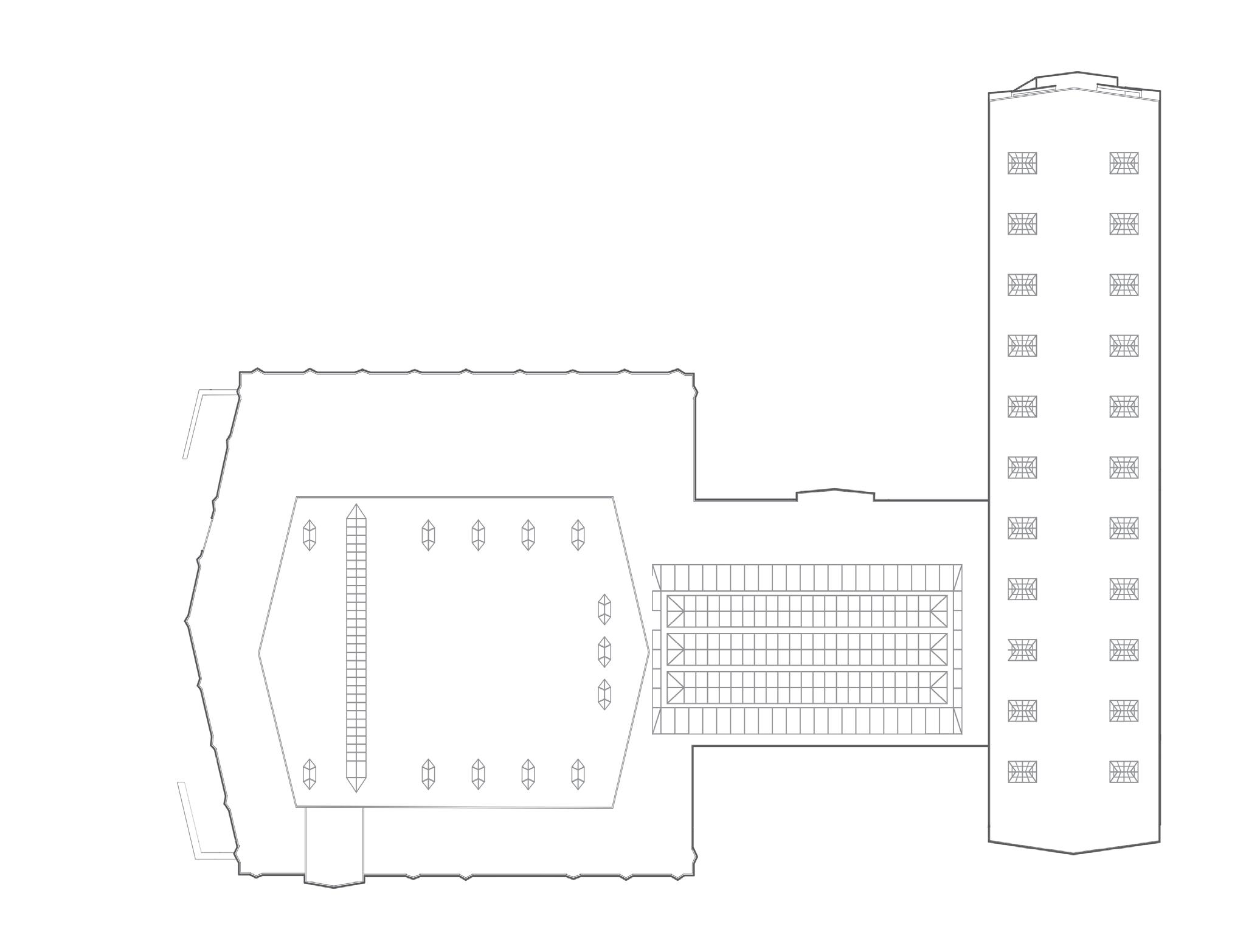


Program Contain: 4th Floor: :

3th FLoor: 2nd Floor: 1st Floor
Theater seating area Office
Theather Gallery Library Classroom Office Practice room Office Classroom Mech Room
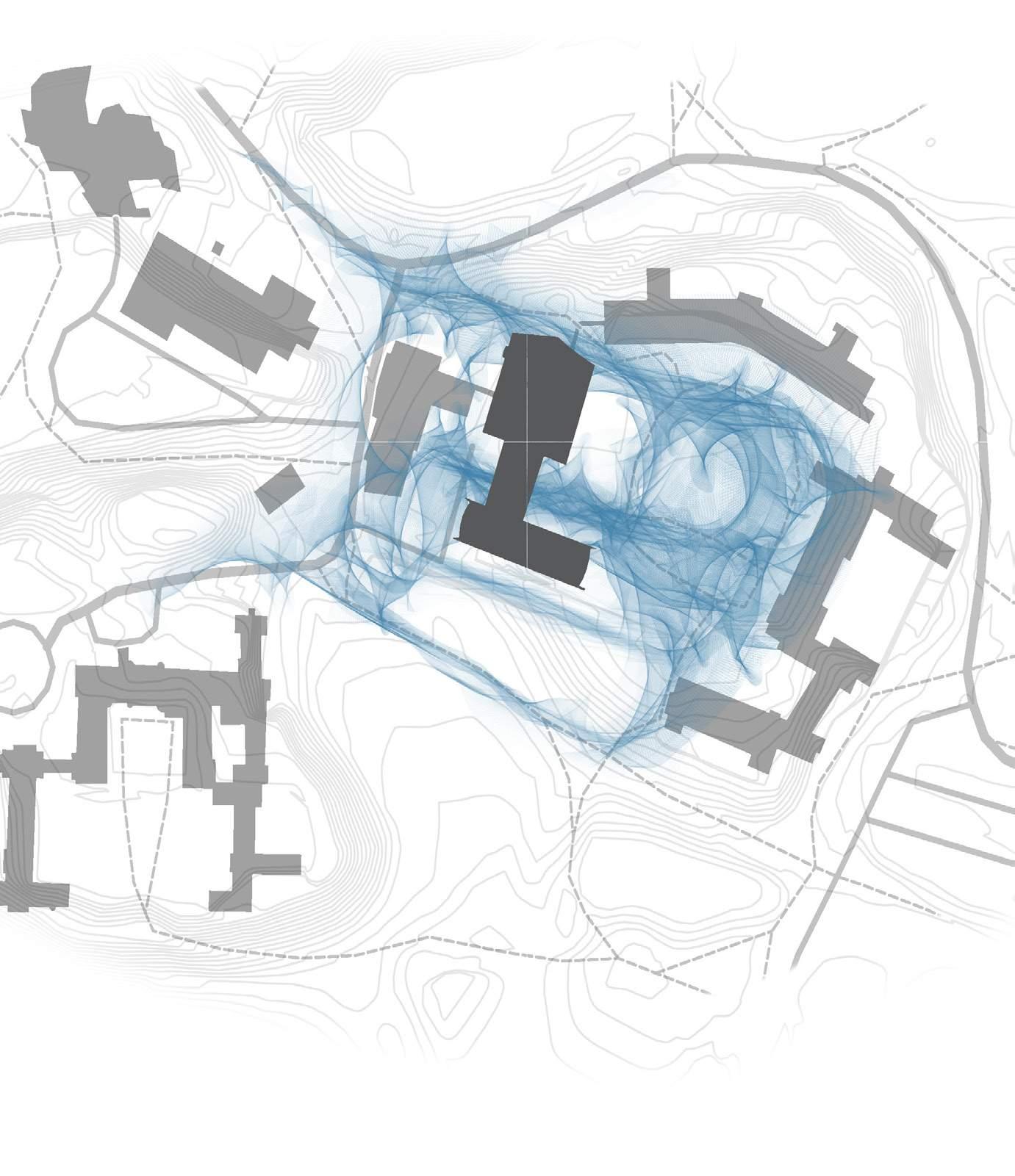
The Mary cooper art center is located at the center of the campus with most of the academic buildings surrounding here which creates heavy traffic in this area. The diagram shows the students’ and faculties’ travel routes between buildings, and how they interact with the facilities.
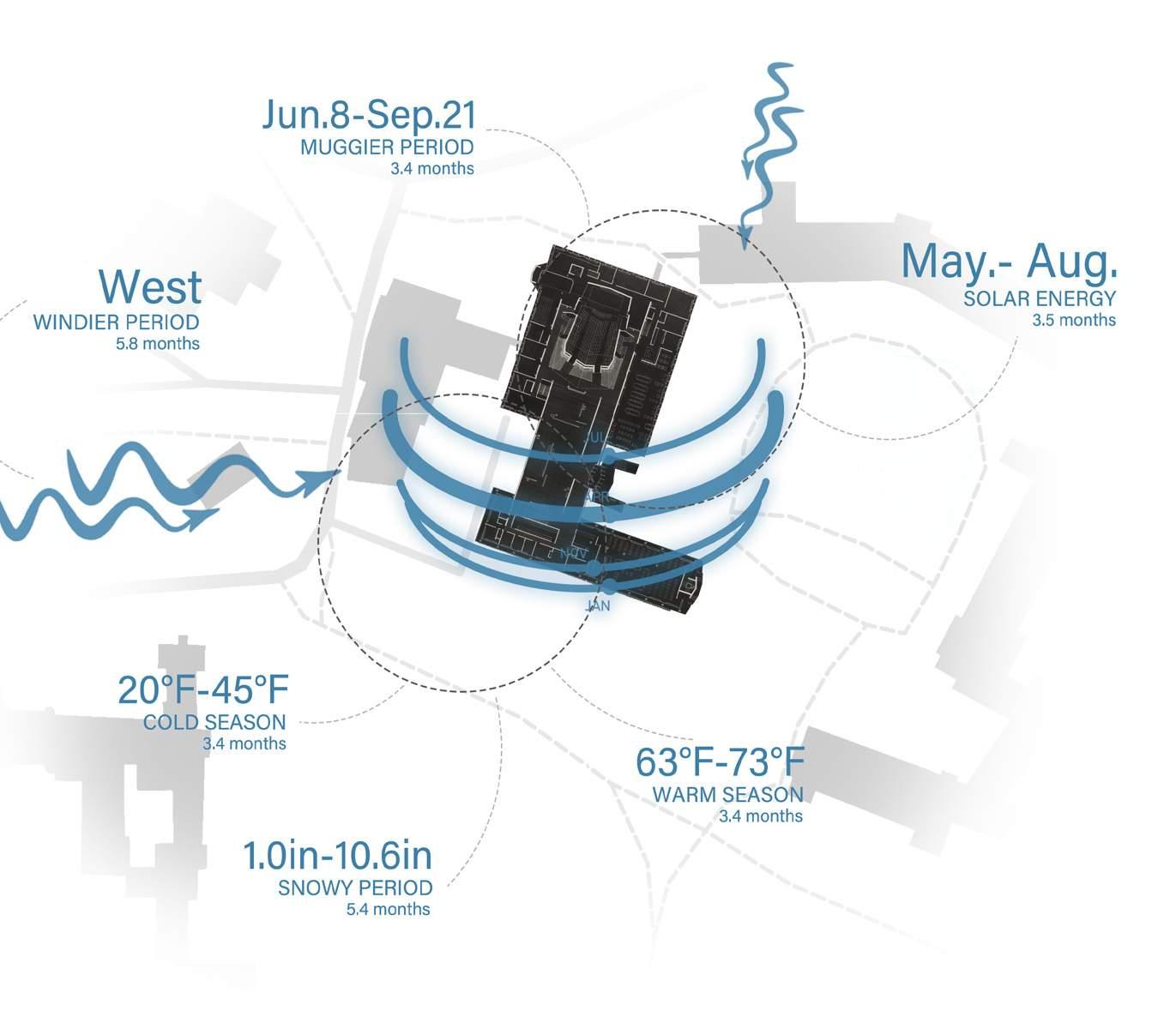
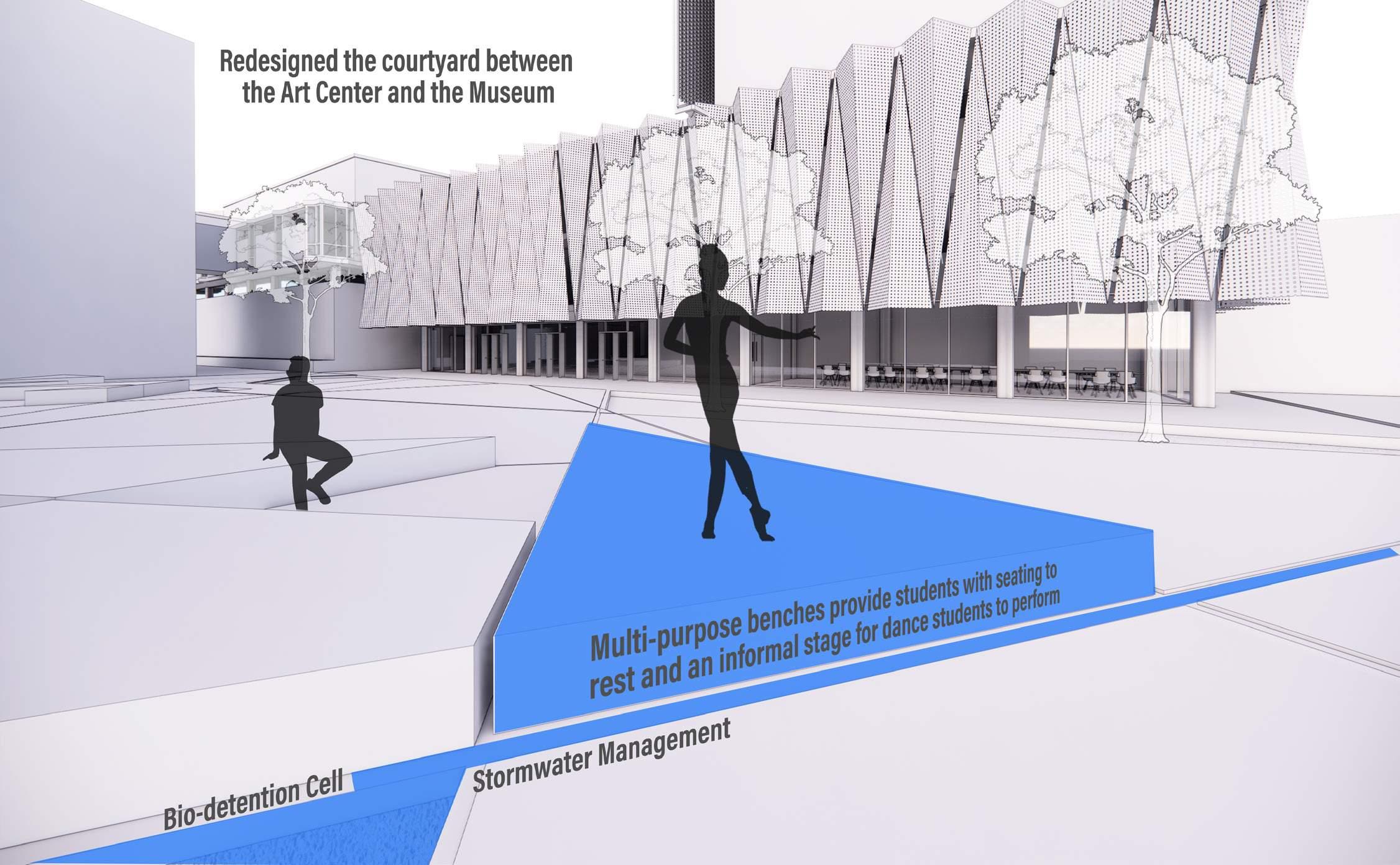
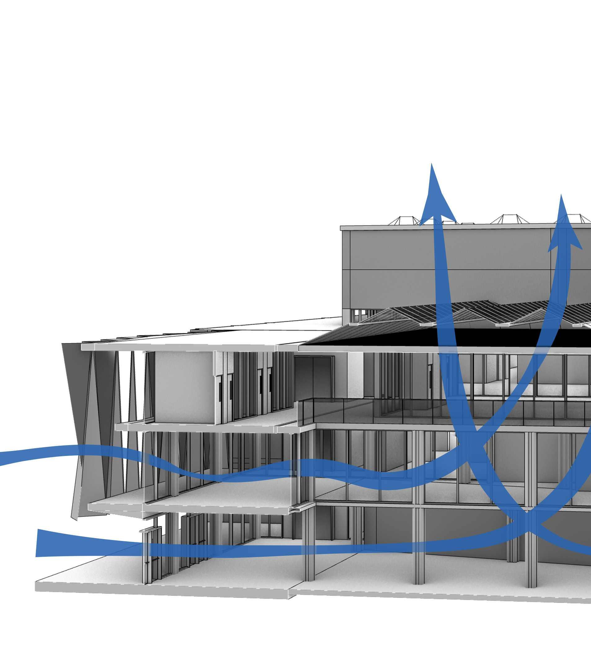
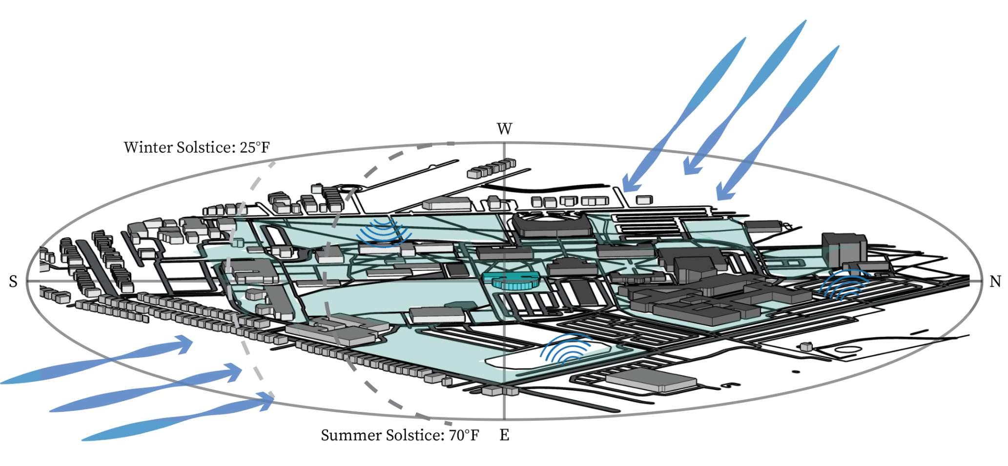
The climate in the Wellesley area is considered a cold climate zone. Half of the year the area will be covered with snow, so solar energy will not be efficient on the campus. the west face of the building is exposed to direct sunlight and requires full shade. West wind is consistent throughout the year. The existing tunnel serves as a wind tunnel in this case.
Analysis and update of the current energy system. Follow the Wellesley college strategic sustainability plan to achieve carbon neutral achievement. The goal is to identify the problem of the current energy system and usage and offer a better solution when updating and expend from the current infrastructure
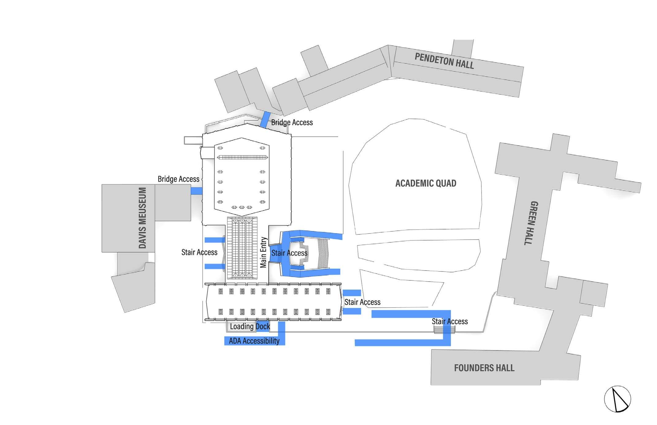
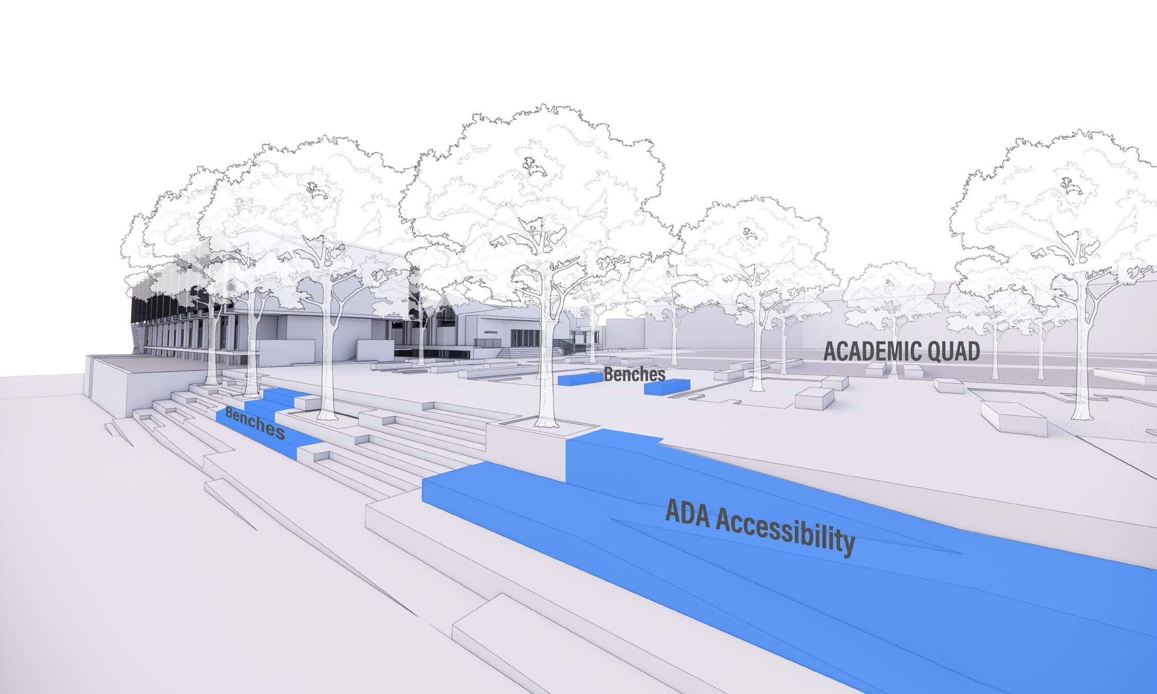
Understand the current student, staff, and faculty circulation related to the architecture. Improve the current circulation and comply with current ADA requirements. With the new circulation diagram, it provides better and safe circulation for users occupying the facility.
Evaluating the program and spaces of the current architecture. Understand the change over time after different program changes and updates throughout the building. Understanding the space limit and programs which need to be expended. Relate with the circulation and sustainability needs, provide better space planning for current educational needs.
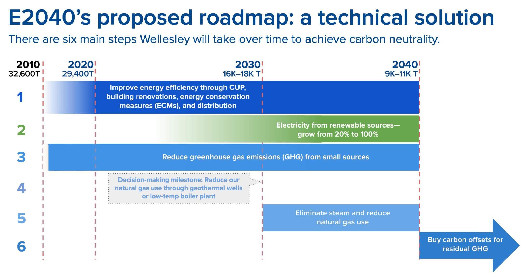
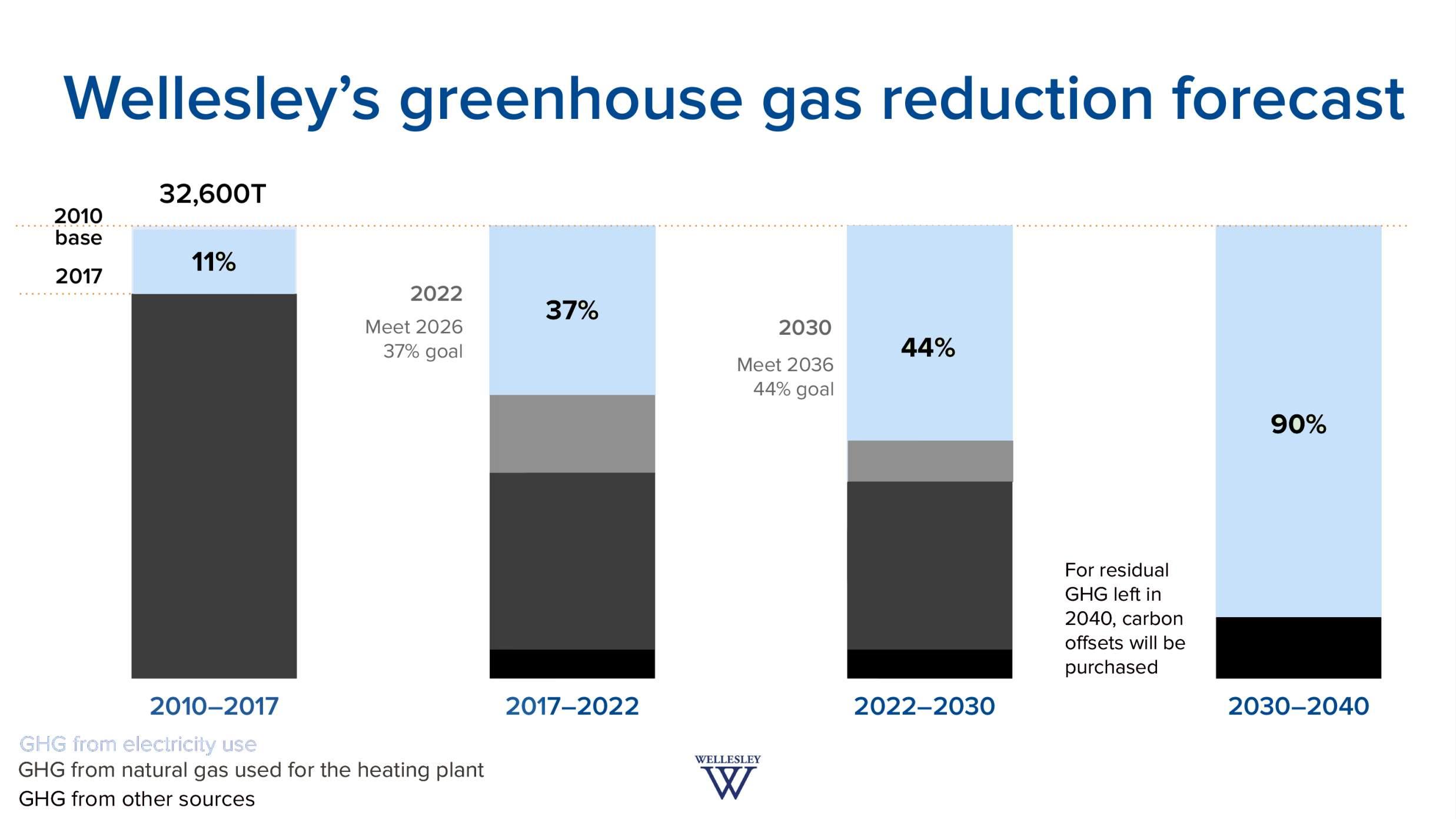
There are six main steps Wellesley College will take over time to achieve carbon Neutrality
2024’s Proposed Roadmap: A Technical Solution
There are six main steps wellesley college will take over time to achieve carbon neutrality
inabilityr Jewett Art Center
essing global challenges that Wellesley students will face in the twenty-first century is global climate change. Wellesley College has and will change through its activities as an educational institution: the courses and programs we offer, our faculty’s research, and the work of our stu portant contributions to addressing climate change. The college also aims to align its institutional practices with these efforts. Building on We mitment to global leadership, energy efficiency, environmental responsibility, and financial stewardship, this plan proposes that the college ad missions by 37% by 2026 and 44% by 2036 from a 2010 baseline. These targets should be re-assessed at least every five years, and long-te neutrality should be pursued.
2040’s Goal
1. A Plan with specific Targets that charts an achievable Path to Carbon Neutrality
2. A plan that addresses all types of energy usage
3. A process that builds understanding, commitment, and enthusiasm for the plan across the community
4. A process that spurs environmental advocacy in all policy arenas
h specific Targets that charts an achievable Path to Carbon Neutrality t addresses all types of energy usage that builds understanding, commitment, and enthusiasm for the plan e community that spurs environmental advocacy in all policy arenas
rrent AHU system and chilled water system s renovted in 1993. The system do not include en de-commissioned due to mechanical failures.
e architecture haven’t been updated with any tem since 1993, and no sustainability strategics en appied to Jewett Art center.

was renovted in 1993. The system
entering each building wing within

been de-commissioned due to m
Current AHU system and chilled w was renovted in 1993. The system been de-commissioned due to me
The Central Plant provides mediumpressure steam and chilled water via underground distribution to the Jewett Arts Center. The Music Wing and the Art Wing are provided with separate incoming services entering each building wing within ground-level mechanical spaces.
The architecture haven’t been up system since 1993, and no susta been appied to Jewett Art center.
The architecture haven’t been upd system since 1993, and no sustain been appied to Jewett Art center.

e Central Plant provides medium pressure steam and chilled water via underground distribution to Jewett Arts Center. The Music Wing and the Art Wing are provided with separate incoming services ering each building wing within ground level mechanical spaces.
The current AHU System and chilled Water system were renovated in 1993. The system does not include dehumidifier function and the humidifier function have been decommissioned due to mechanical failures.
The architecture hasn’t been updated with any system since 1993, and no sustainability strategies have been applied to Jewett Art center.


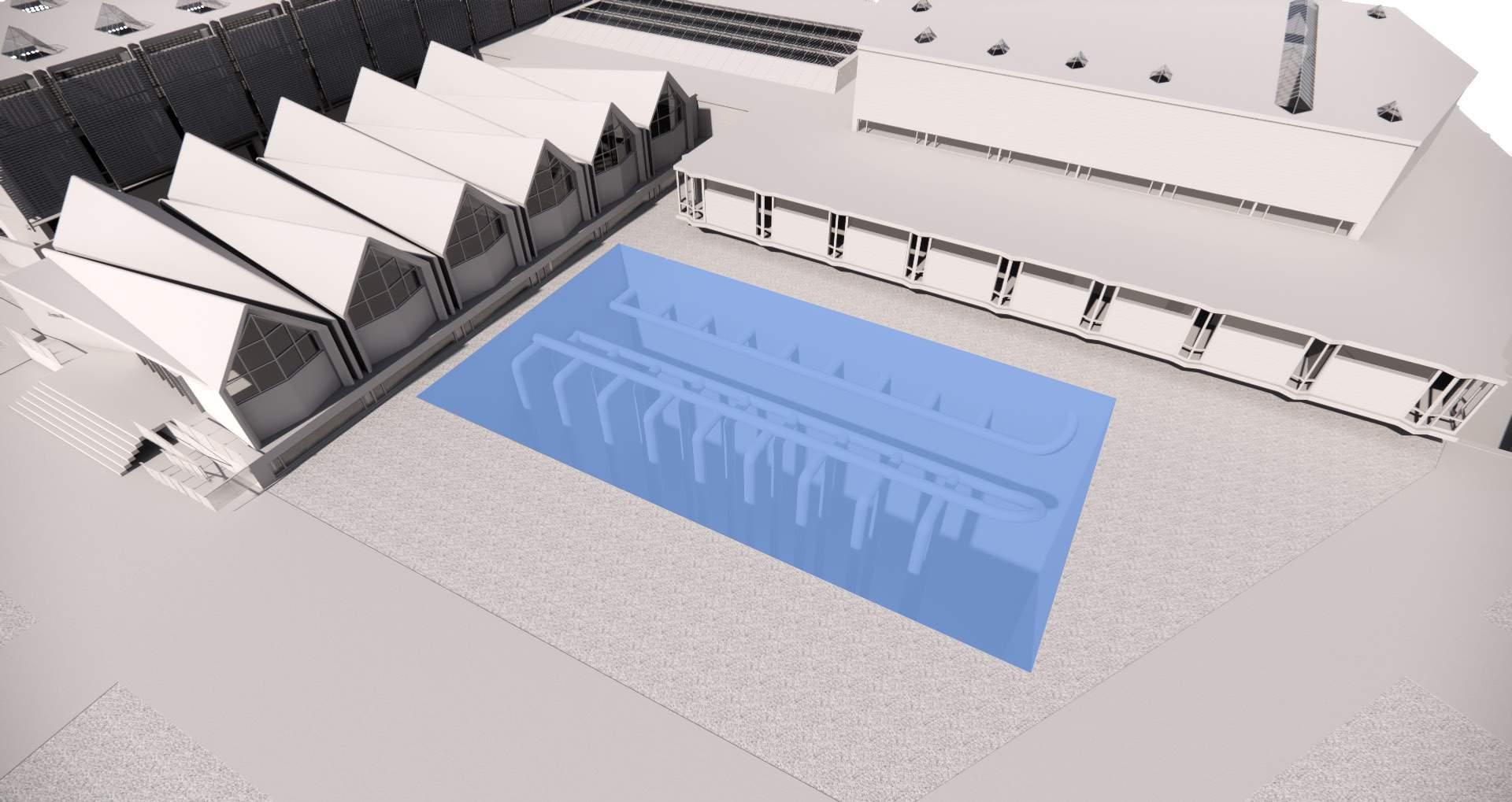
Geothermal Heating & Cooling system Saves 40%-60% of electricity compare with regular HAVC system,
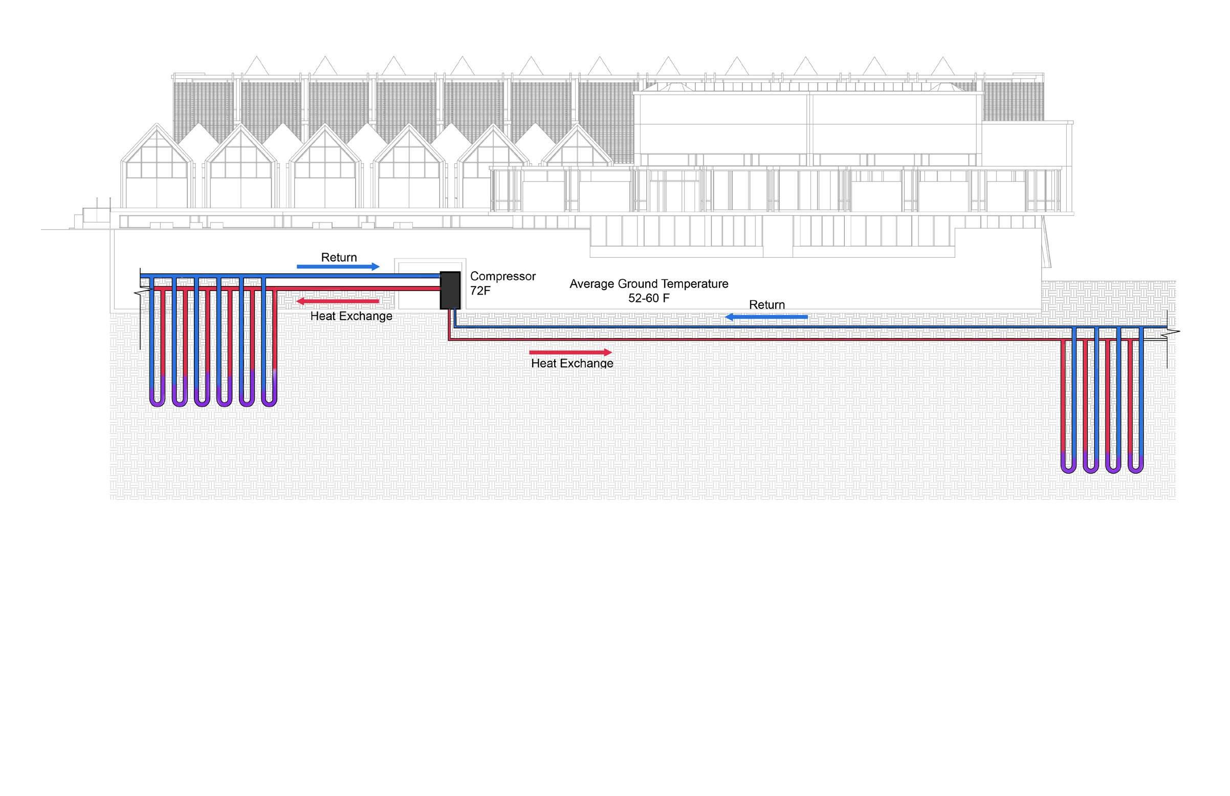
The total square footage of the building is 132,000 SF, Average Annual electricity consumption 2,5000,000 KW
Average 31% of the energy consumption is HVAC apoximate750,000KW Equal to $97500.
With geothermal Heating & Cooling system, Wellesley college can save approximate $48000 in electricity bill.
Geothermal Heating & Cooling system also has very low maintenance cost Regualr HAVC system has life expectancy around 10-15 Years
Geothermal Heating & Cooling System Heat pump life expectancy is 20 years Pipe system is 50 Years

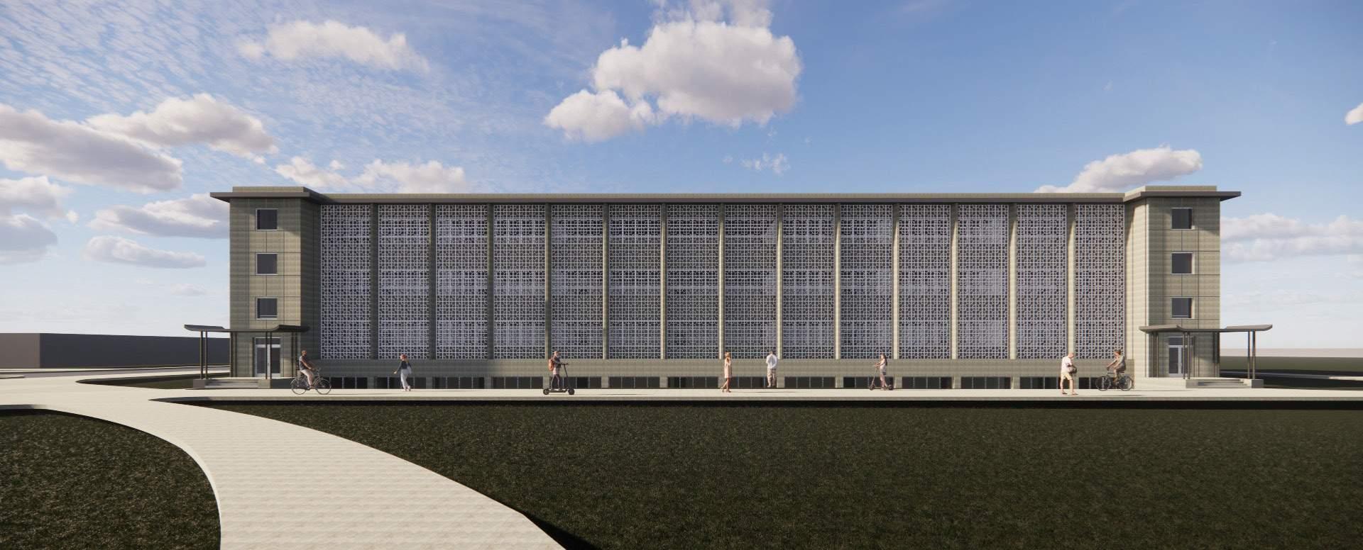
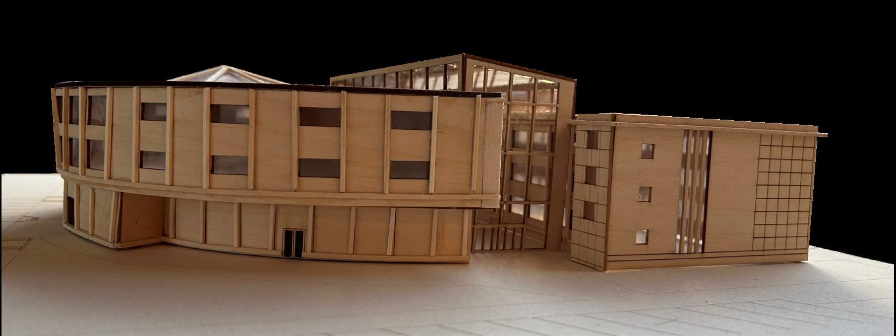
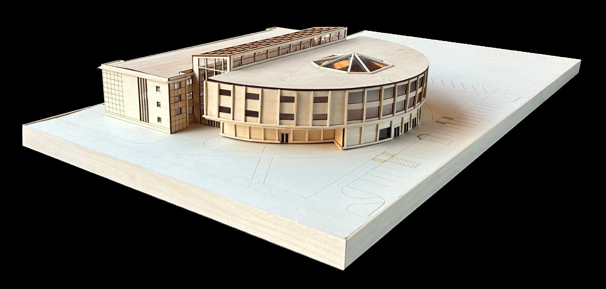
This project will focus on adaptive reuse and expansion to an existing lecture hall at the University at Buffalo. The goal is to learn from previous constructions while incorporating new adaptations and growth to the building and its program, giving the building a “second life” with a current, sustainable approach.
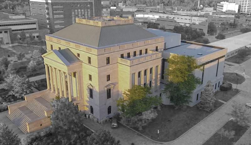
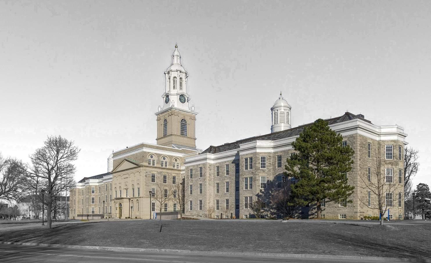
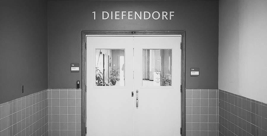
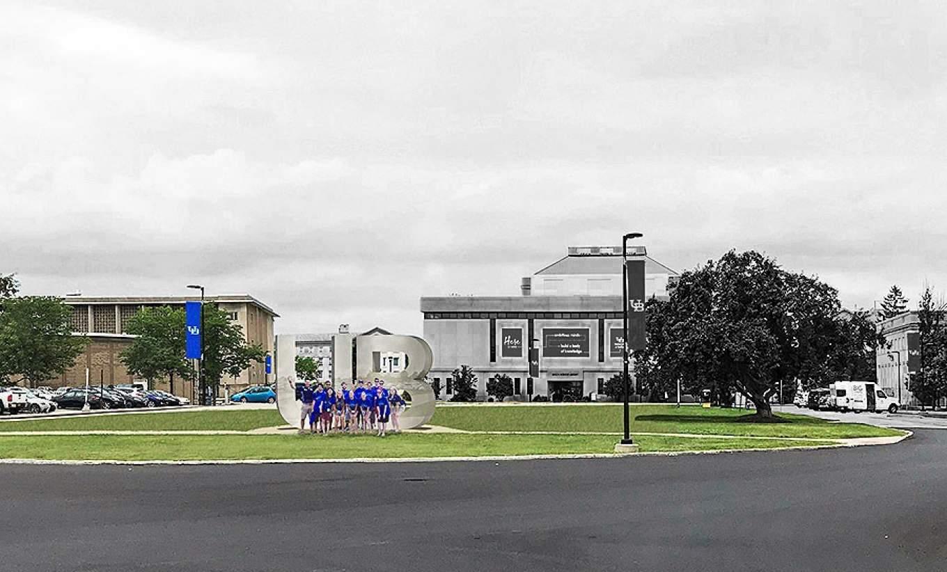
Diefendorf Hall is a focal point of the University at Buffalo South Campus. It has great potential to allow the local community to be welcomed onto campus while also being
an engaging place for the students on campus. The goal of the project is to engage with the student community by providing additional spaces for informal interactions, study spaces,
and additional library resources. The project also provides publicly accessible functions such as a cafe and courtyard, turning Diefendorf Hall into a more equitable renovation and expansion.
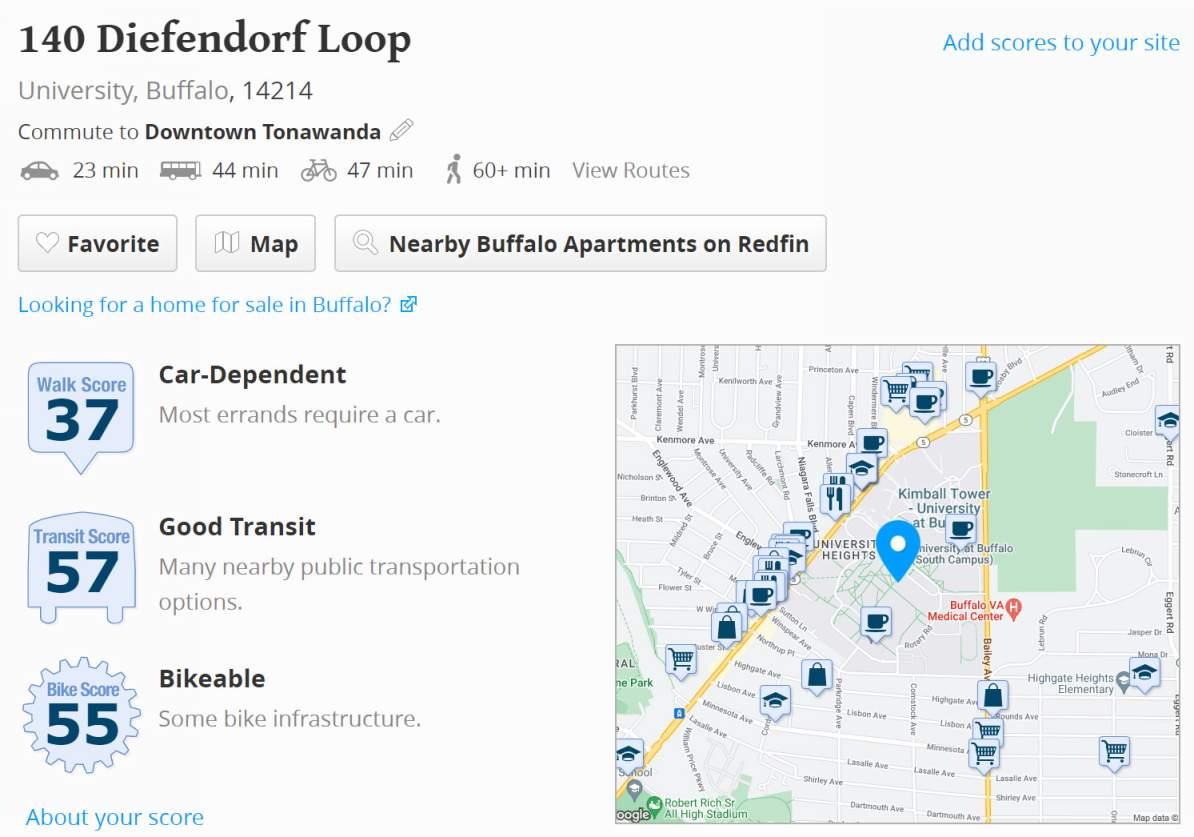
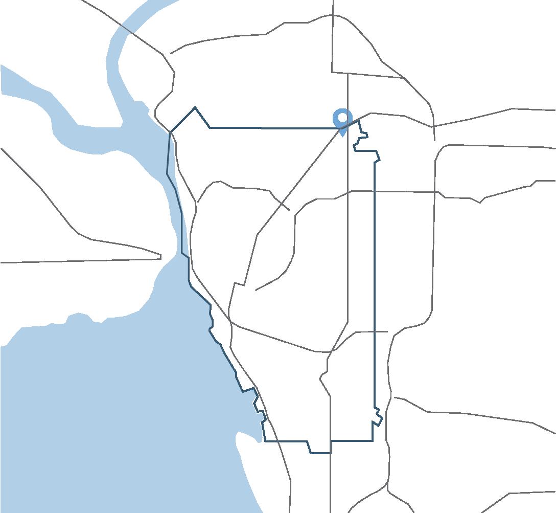
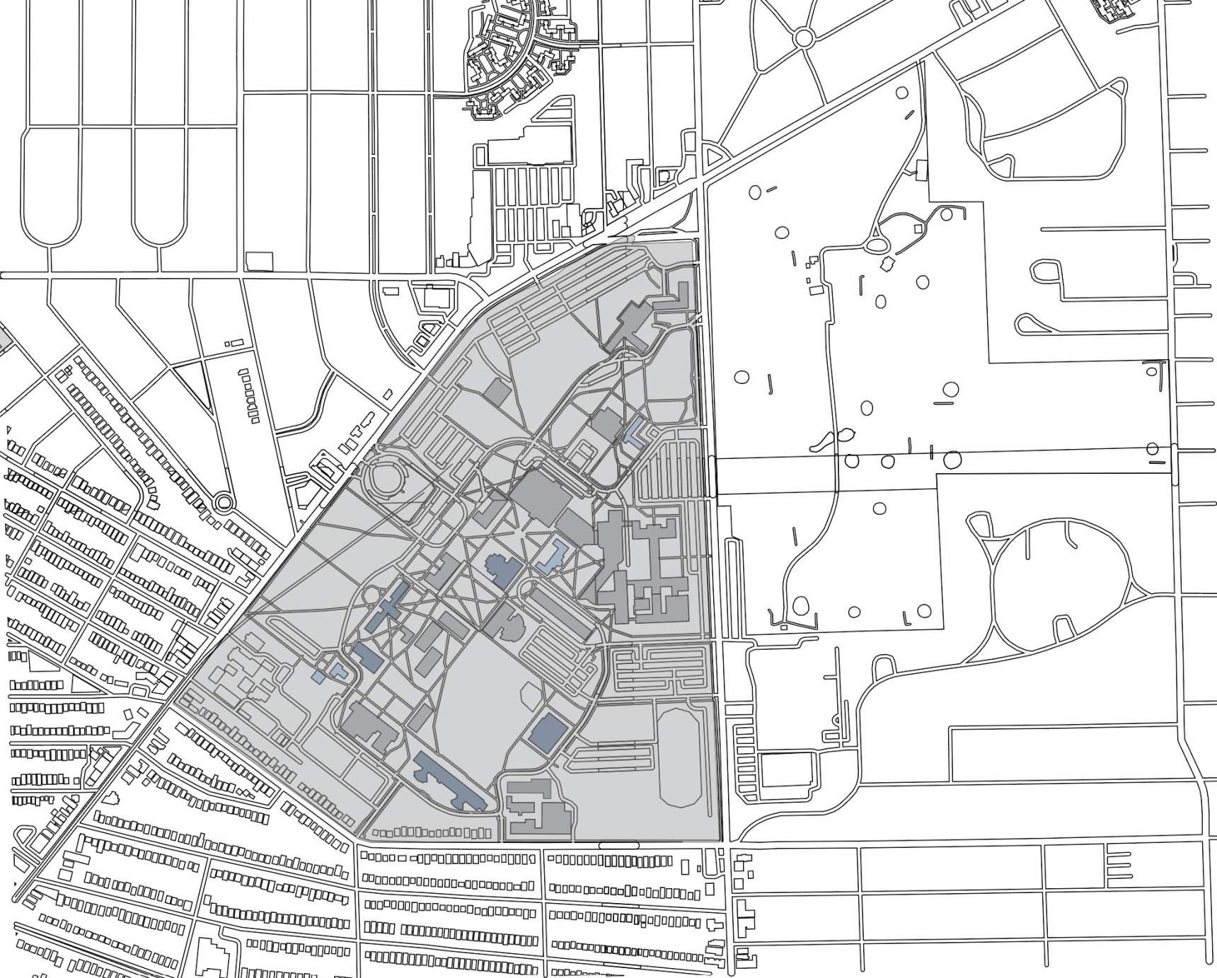
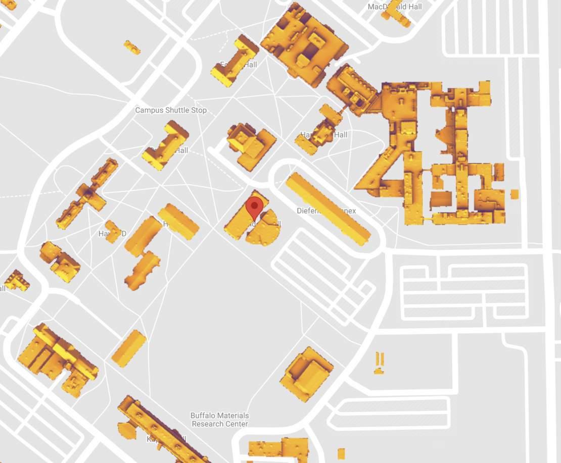
The University at Buffalo - South Campus is located in the north-east corner of the city of Buffalo, New York.
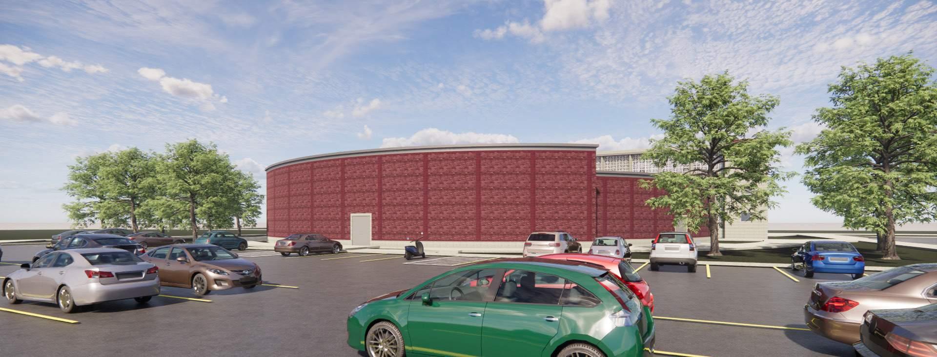
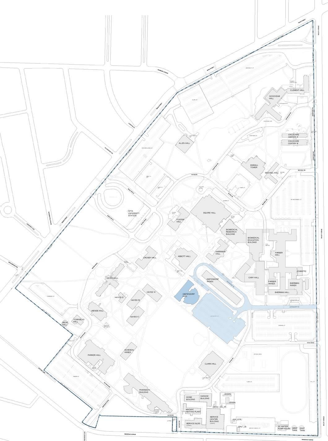
On the University at Buffalo South Campus, Diefendorf Hall is centrally located with a main access road and parking lot to the east side of the building. There is a large field and loop called the “Diefendorf Loop” that is going to become one of the campus’ new focal points for visitors coming to the school.
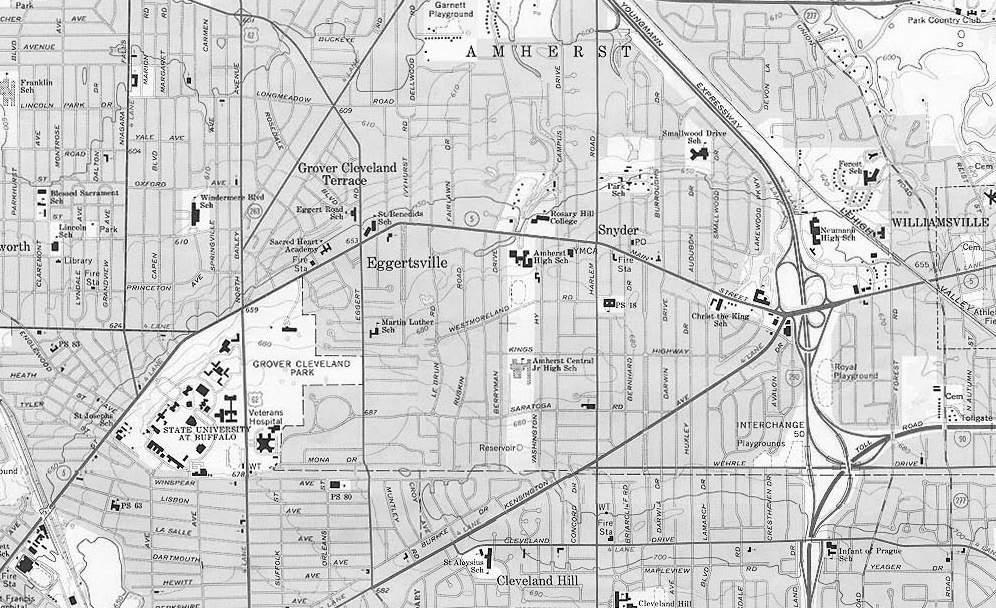
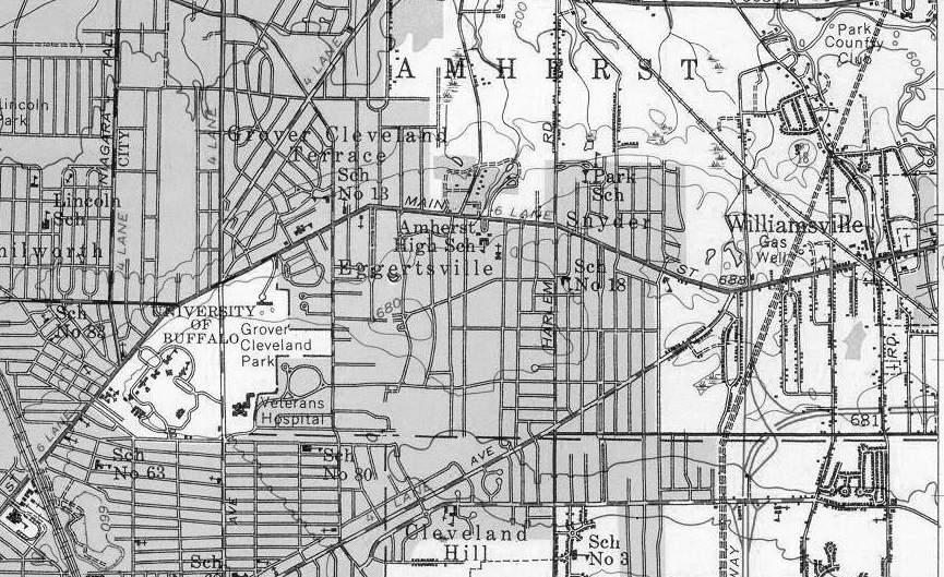
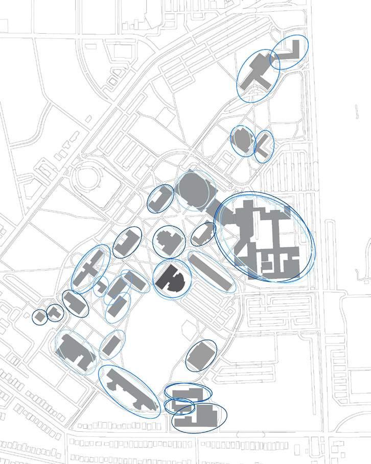
The Buffalo vicinity maps showcase the growth of the community surrounding the University at Buffalo’s South Campus from 1948 - 2022. There is clear evidence of a rapidly growing commmunity not only for the city but for the university as well. Recognizing this emphasizes the importance of finding ways in which the University at Buffalo can be engaged with, not just located within the community.
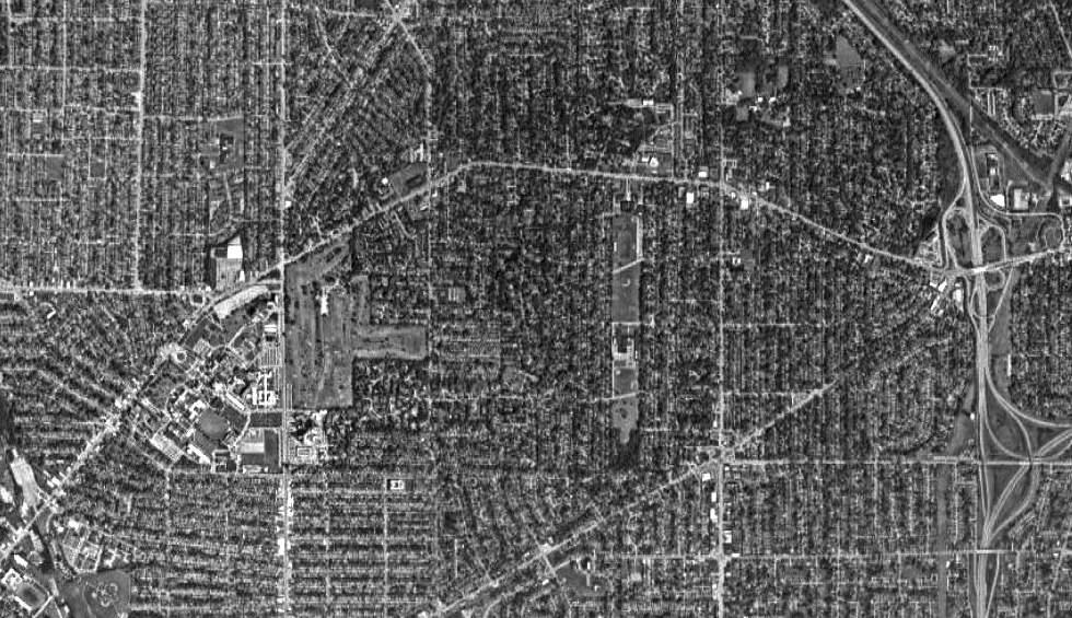
The University at Buffalo was founded as a medical school for a growing city.
The South Campus for the University at Buffalo was formally dedicated, taking over the existing Erie County Almshouse and County Hospital


The University at Buffalo began adding other programs such as law and dentistry
One of the nation’s first business schools was established at the University at Buffalo, with the goal of training business managers for the community
E.B. Green & Son and Albert Hart Hopkins developed the south campus plan, as well as the buildings to be constructed

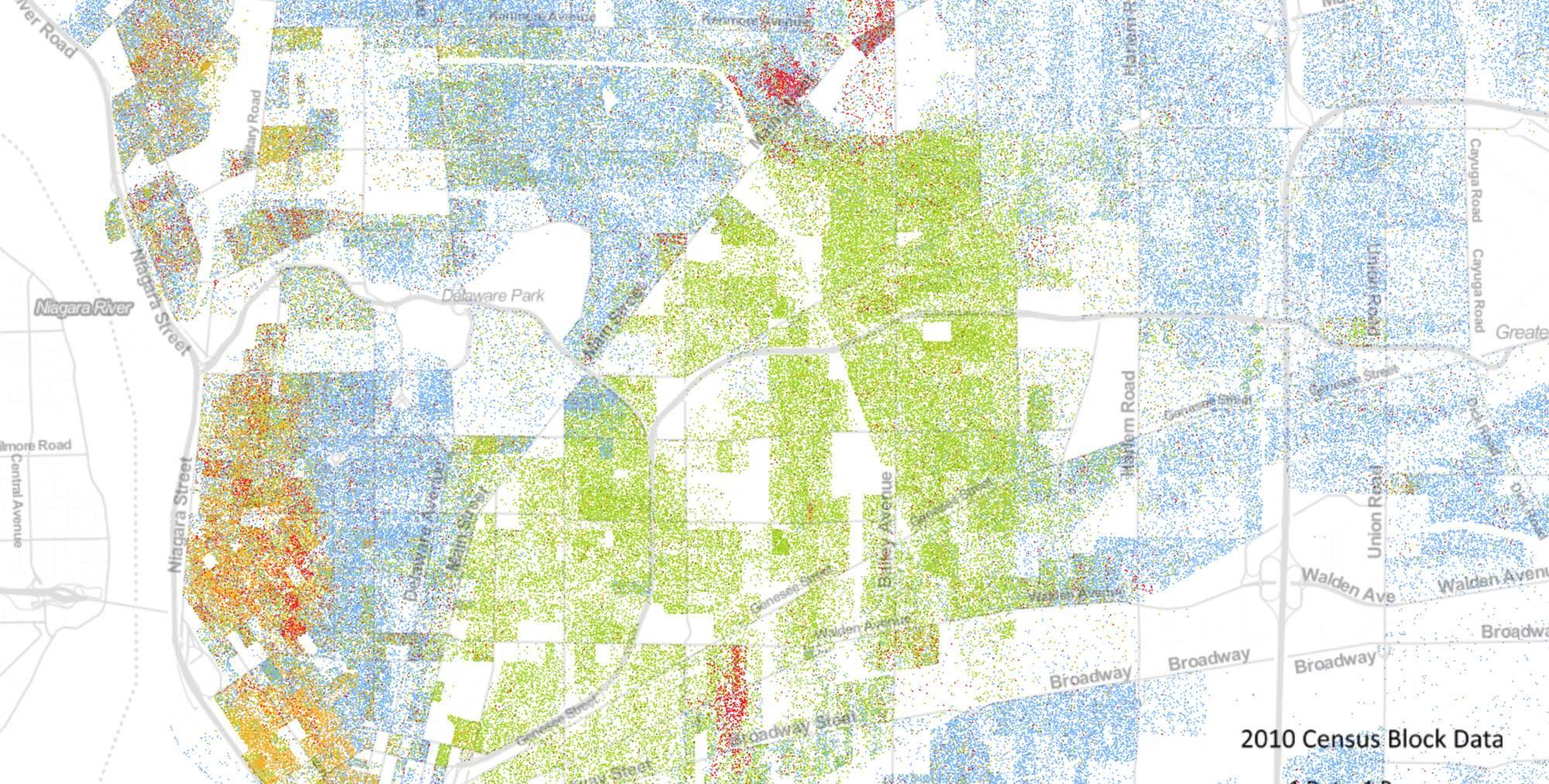
Housing segregation was seen in the form of restrictive covenants, redlining, and blockbusting. This history has created clear separations between
races in the geography of Buffalo. Buffalo has slightly declined in racial segregation over time, but has an extremely high amount of economic
segregation which can have impacts on health, education, job access, etc. resulting in a lower standard of living.
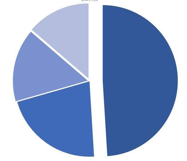
WHITE: 50%
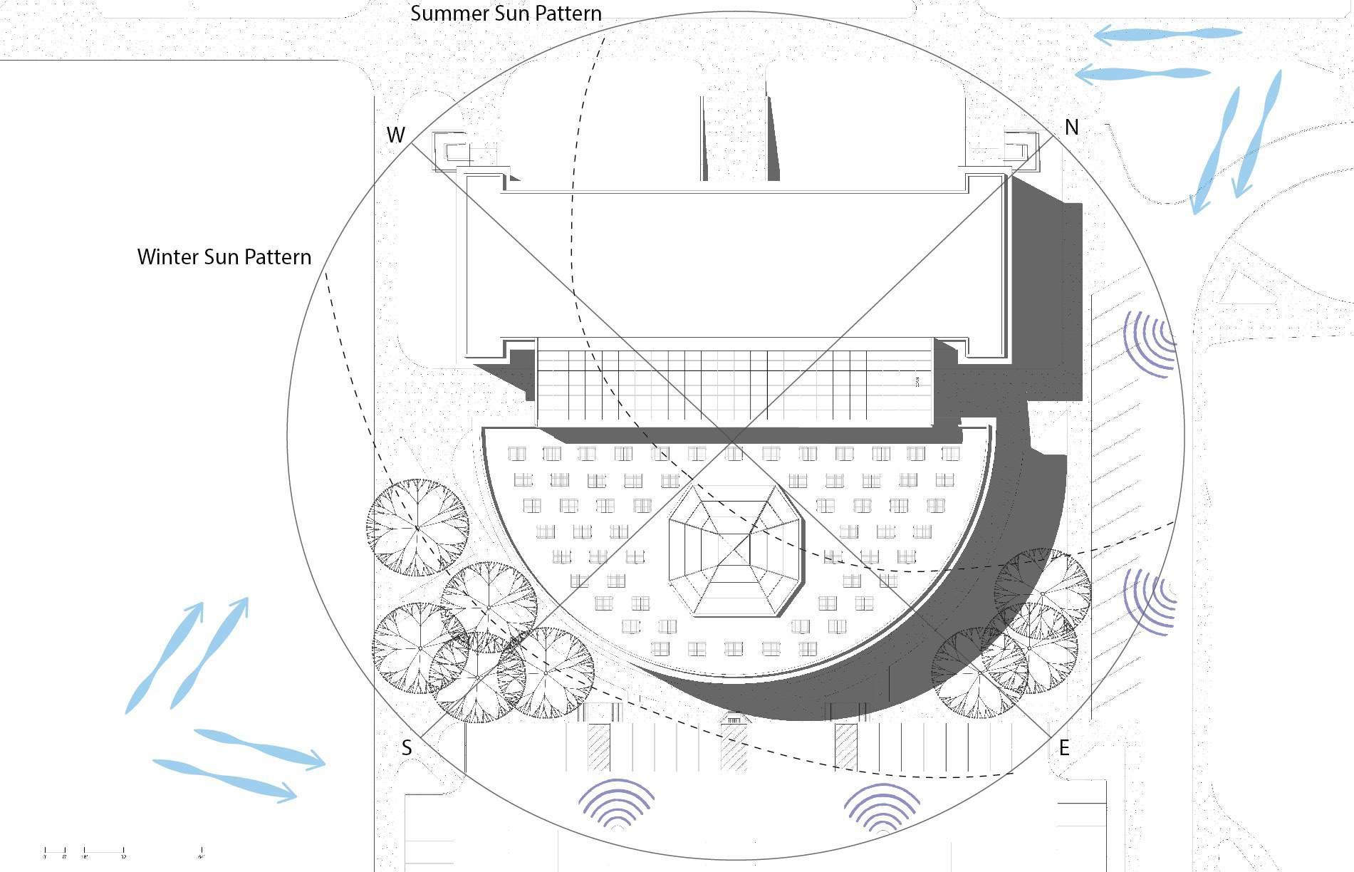
The map indicates the wind patterns during the fall and spring seasons, the typical high-level sound noises that come from the surrounding streets,
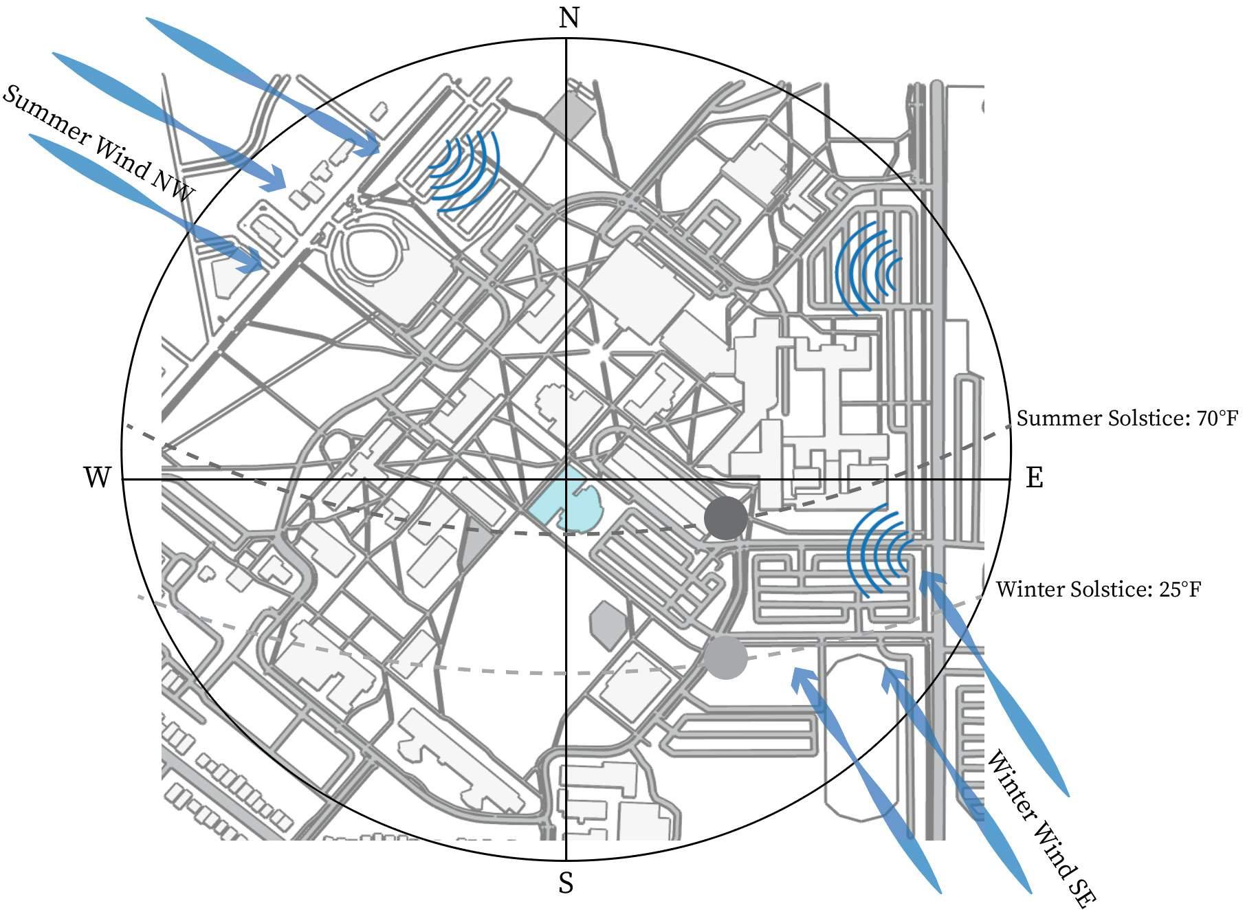
and the winter and summer sun patterns. This is a larger site map to show the surrounding buildings and landscape, and how they impact the
site immediately surround Diefendorf Hall.
The University at Buffalo’s goal is to be climate neutral by 2030. They’ve developed the 10 in 10 - Climate Change Action Plan. Included in the
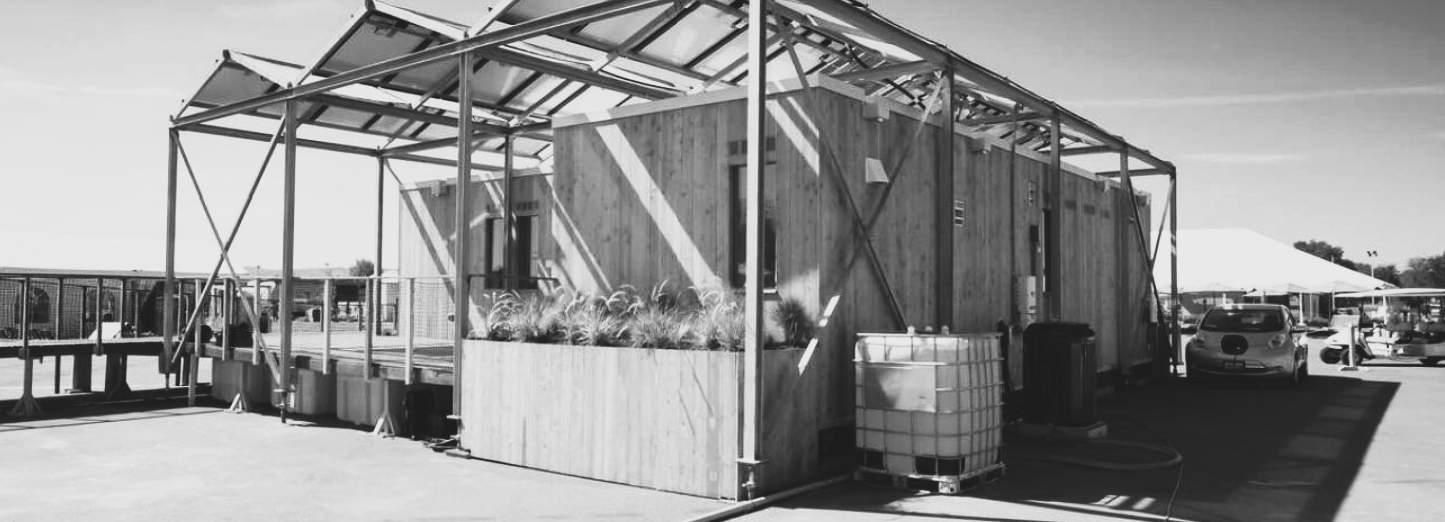
plan is a commitment to purchase carbon offsets to fill any gaps and bring the university’s emission levels to zero. Through efforts like the GRoW
Clean Energy Center, and installation of on-site solar panels, the University at Buffalo is pushing to make a greater impact on climate change issues.

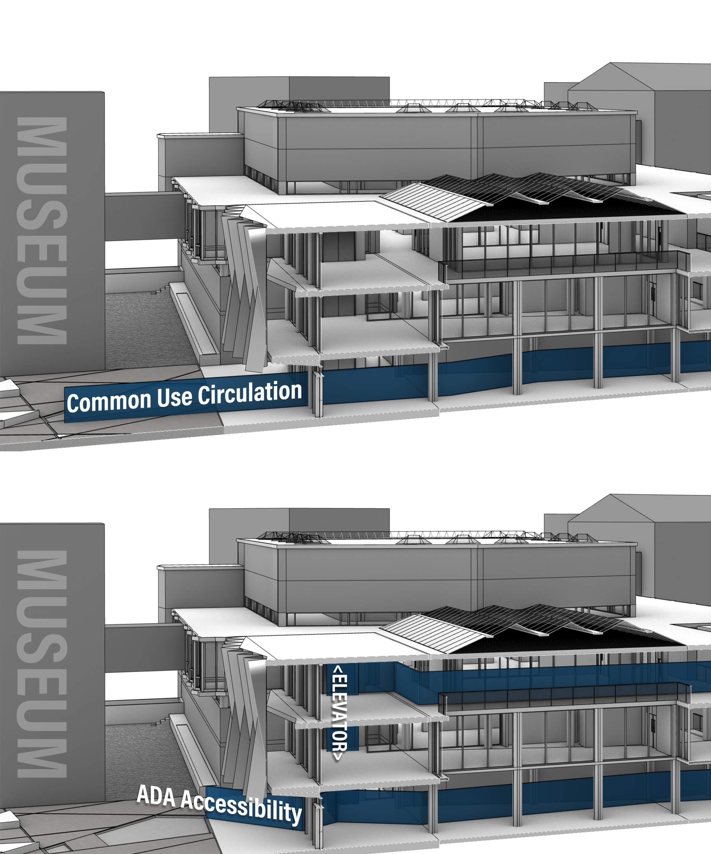
In this exisiting building access and circulation diagram, it indicates the main points of entry into the building. As well as showing the handicapped
entrance and exit doors. The greyed out arrows are all of the access points that are not ADA accessible. This is not an inviting or welcoming
educational building. The only accesible entry is on one side of the building down a ramp that is hidden.
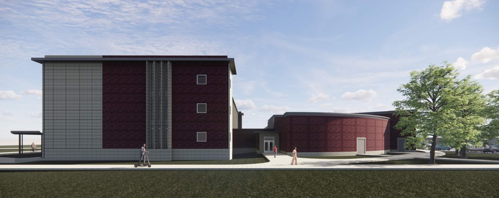
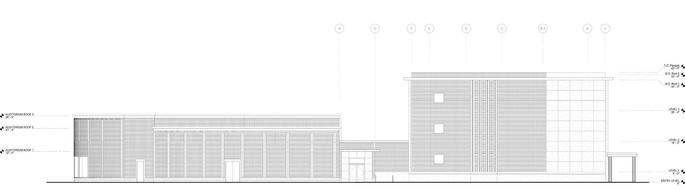
Hayes Hall & Abbott Hall are two of the south campus buildings that shape the identity of the architecture for the school. They are older historic buildings that have a more traditional design approach, but also maintain simplisity in the materials used. The goal is not to overwhelm people with an assortment of different materials that do not have any significance together. Instead the goal is to unify Diefendorf Hall with the rest of campus through unique design continuity of current materials around campus.
The campus circulation map highlights the common path of travel for students from around the campus that would be interacting with Diefendorf Hall. From this map there is evidence that all sides of the building are important access points and should be considered when planning for future adaptation.
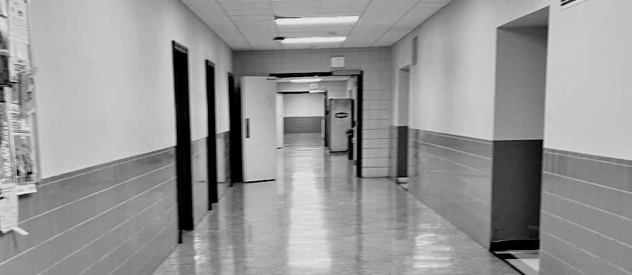
Diefendorf Hall has very dated interiors and does not allow for almost any natural light. Walking through the corridors is an uncomfortable experience that does not encourage anyone to stay in this area, and has minimal considerations for making it an equitable building for all users.
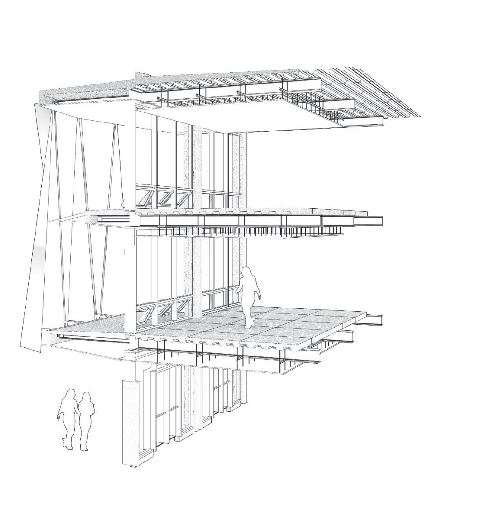
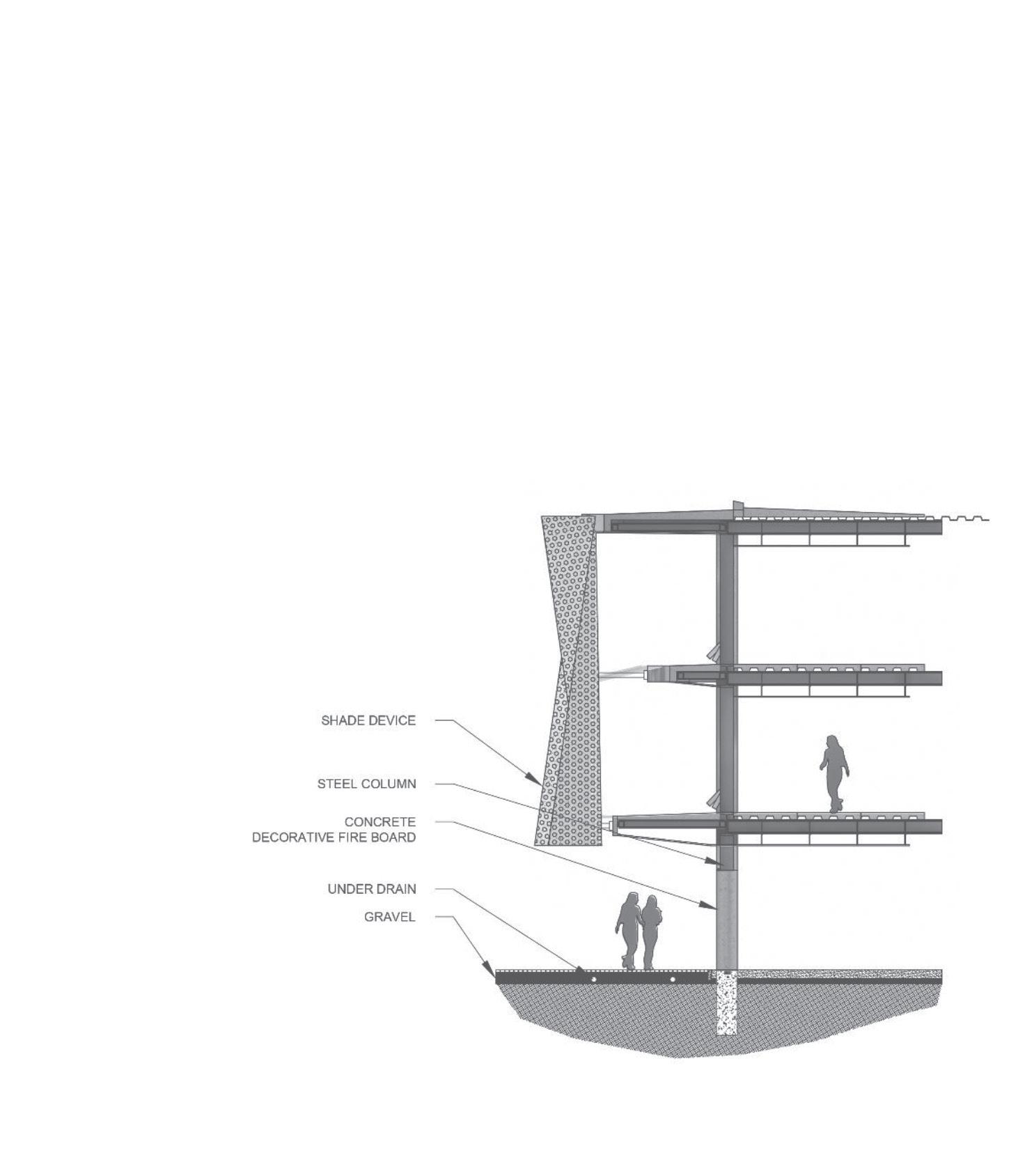
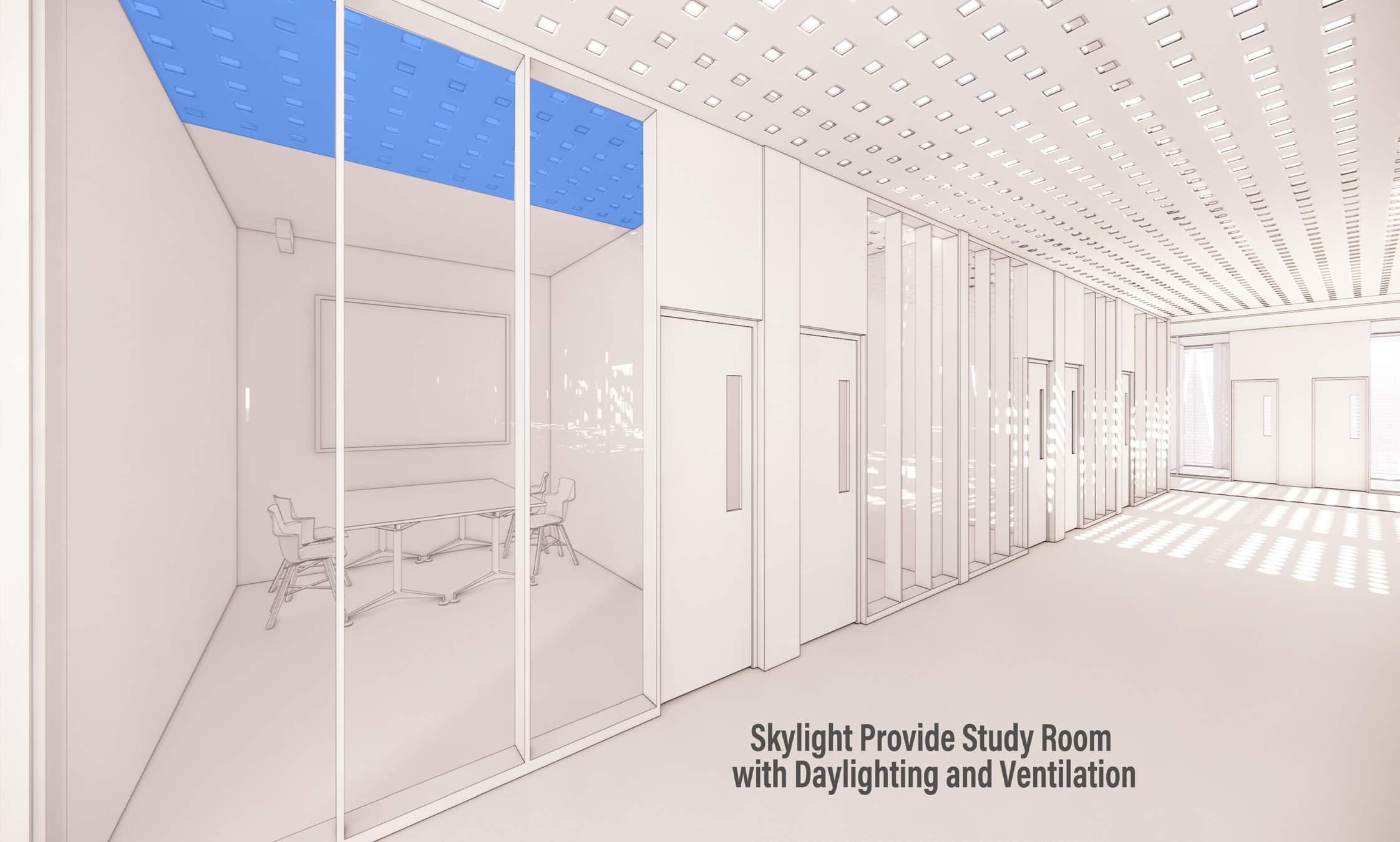
All classrooms and offices have a decorative concrete block outside of the operable windows. While this is a creative architectural feature that is important to the building’s historical design, the block tends to decrease the amount of daylighting in these spaces. This causes each room to be unable to maximize on its passive lighting and heating potential.
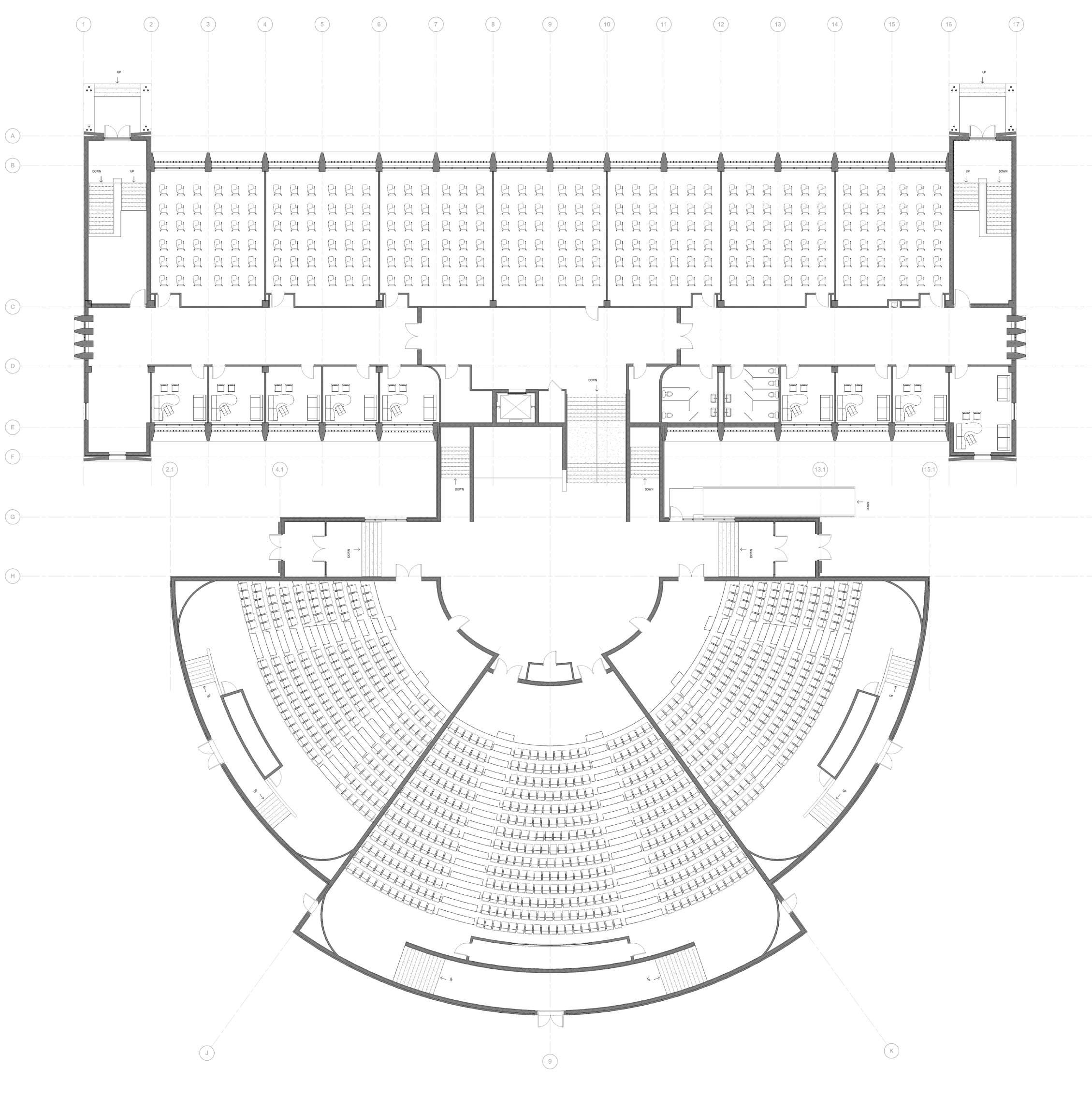
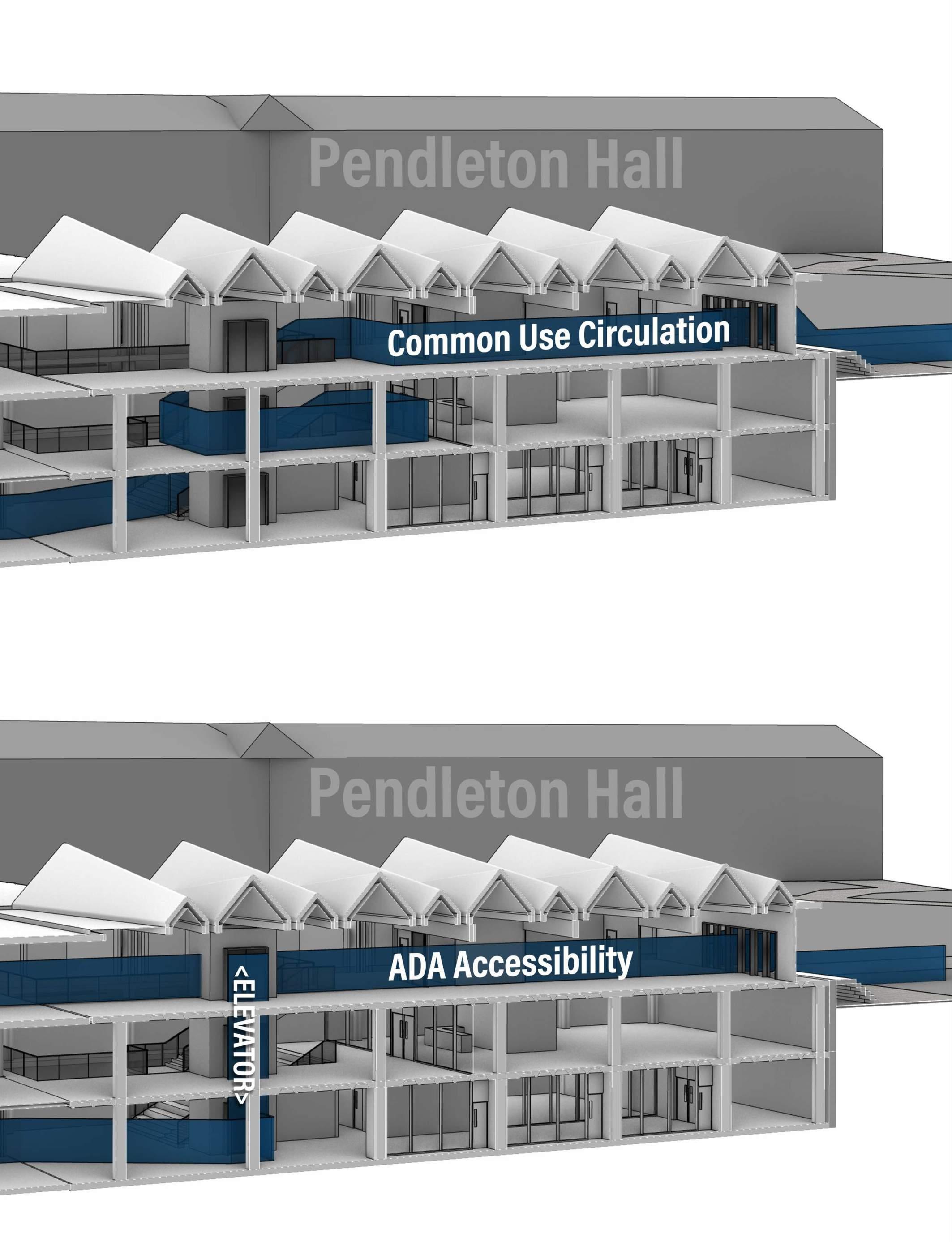
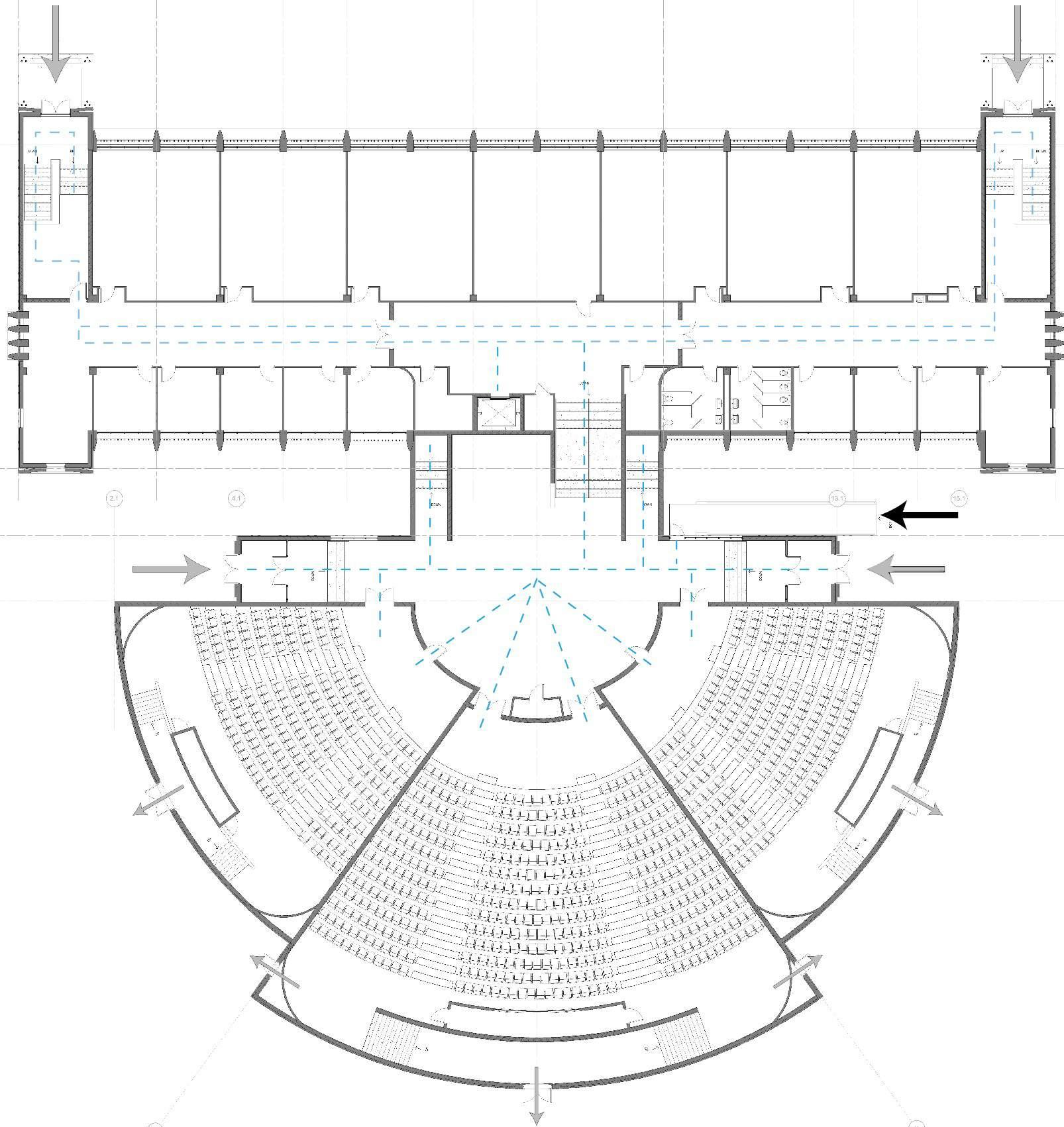
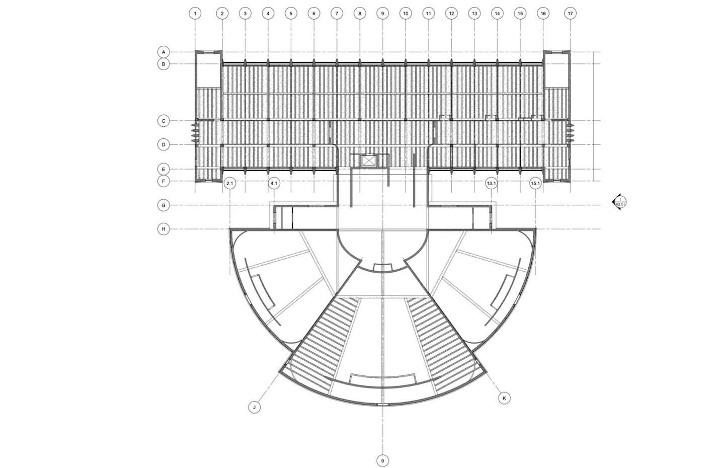
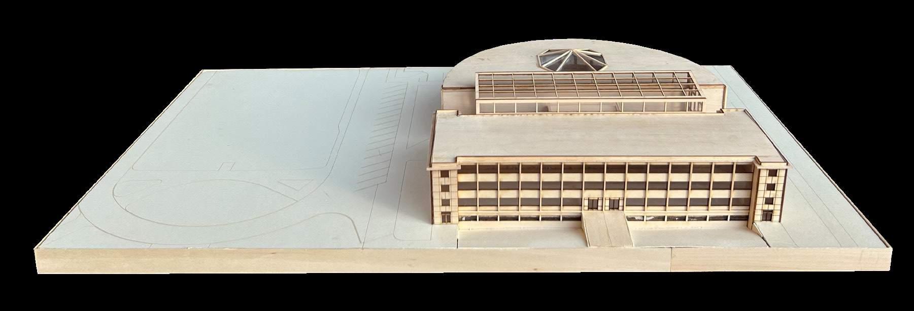
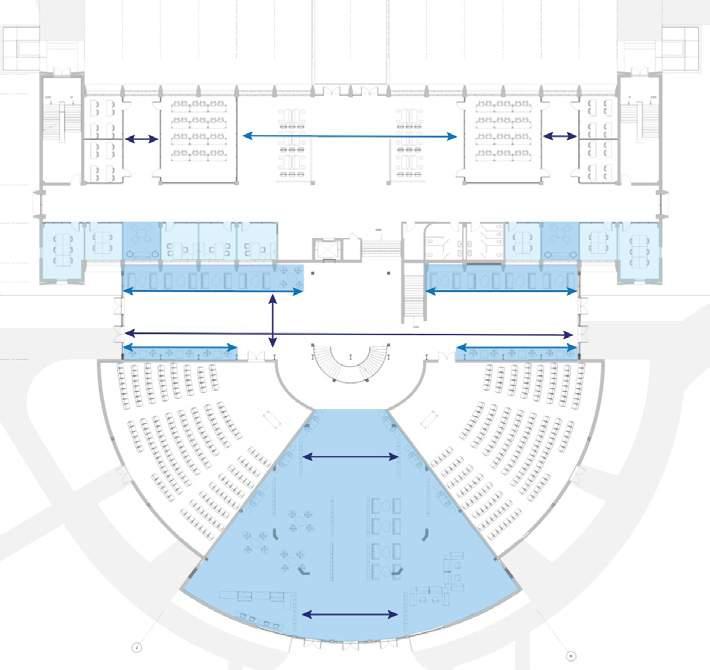
The staggered main floors of Diefendorf Hall contain (3) large auditoriums that are oversized and underused. There are also a low row of lecture rooms along a doubleloaded corridor with offices on the opposite side. Each floor has an identical layout.
For the interiors, a new layout will be need, so only the vertical circulation will be maintained during the adaptation + expansion for this building.
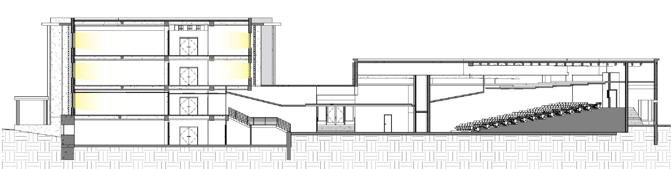
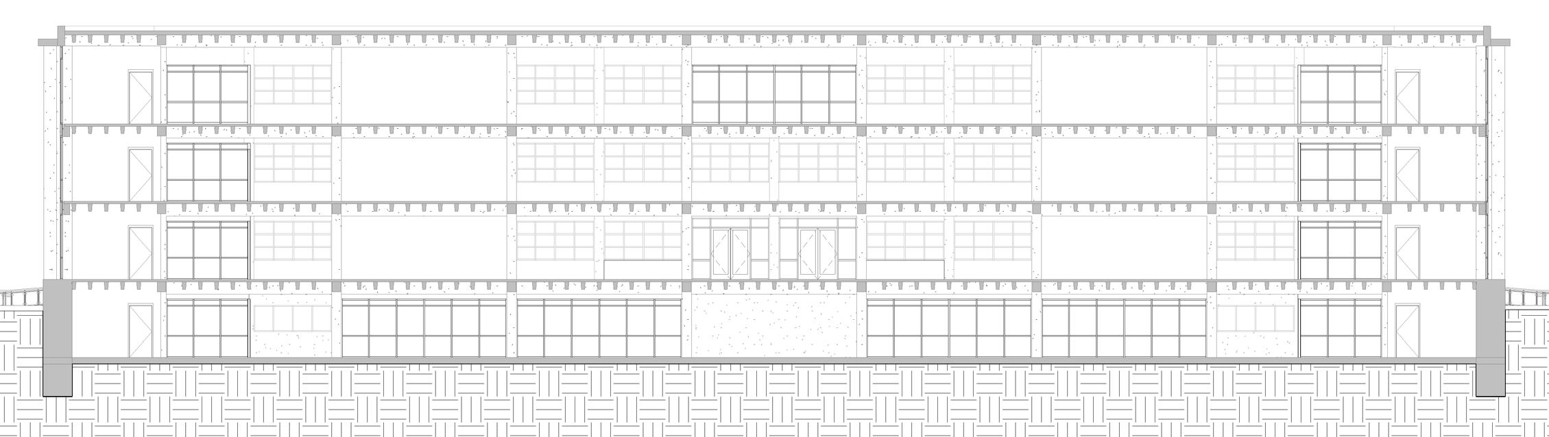
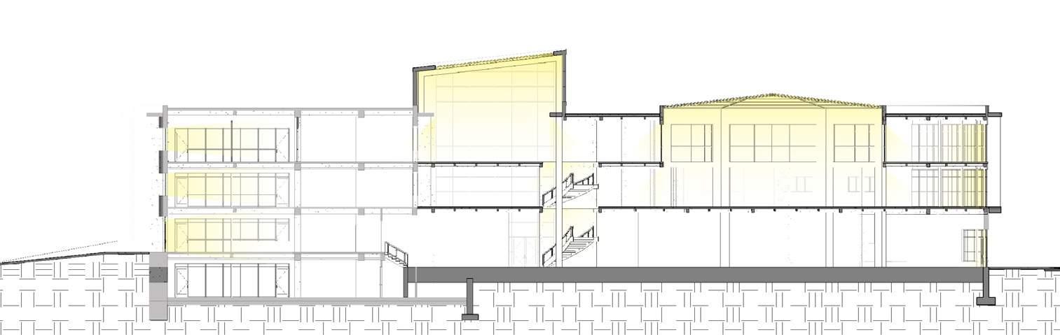
Analyzing the building sections for the current conditions makes it evident how difficult of a building this is to navigate. At every transition of
program in the building, a person is faced with a change in floor level which limits equitable access for people and causes a lack of
cohesiveness between the different sections of the building. Manuevering is very rigid and complicated in a seemingly simple floor plan.
In this diagram, the exisiting building doesn’t allow students to be comfortable. There are no collaboration spaces, social areas etc.
The goal for our proposed design is to create a space for students to have that space to work alone and with other people. The auditoriums didn’t
allow students to have the space for collaboration and socializing, we decided that was our next step in this project.
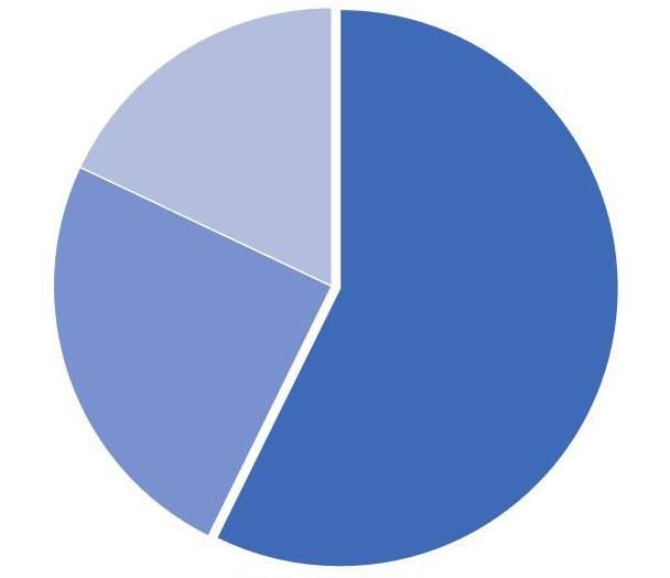
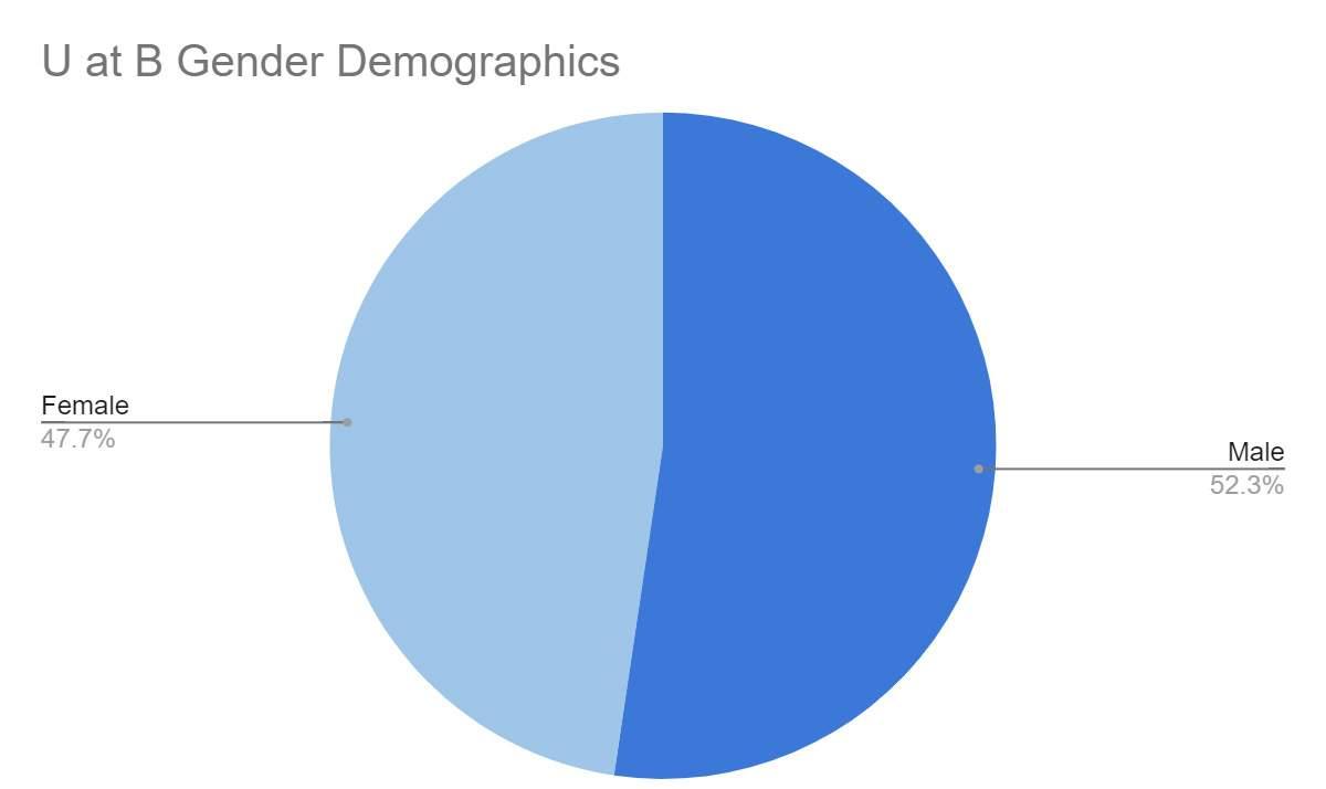
This graph showases the gender demographics of the students at University at Buffalo dating to 2022.
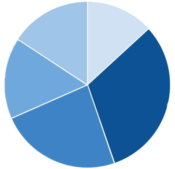
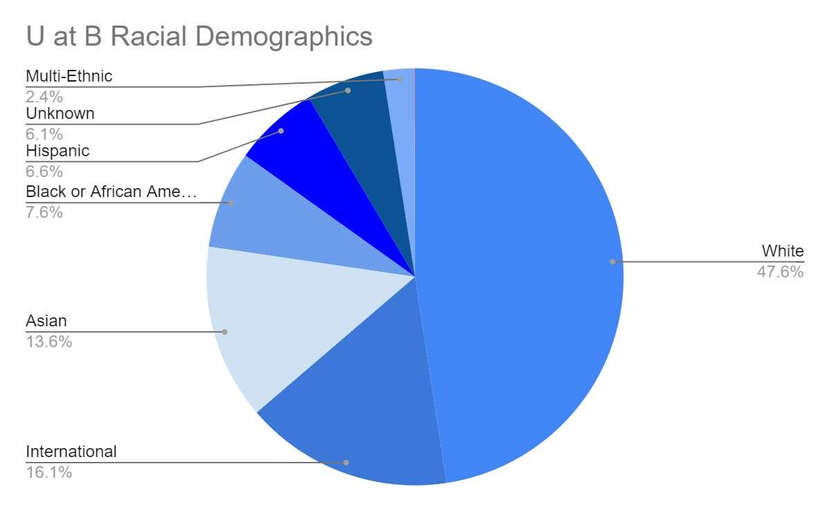
This graph showcases the racial demographics of the students at University at Buffalo dating to 2022. White students make up almost 50% of the population. The next largest is international and Asian students amounting to alost 20% combined. 7.6% of students are black or AfricanAmerican. They are underpresented given that this group represents 35% of Buffalo’s population.
This graph showcases the percent of people living below the poverty line in Buffalo-Niagra according to the American Survey Data, 1-year estimates, dating between 2008-2015.
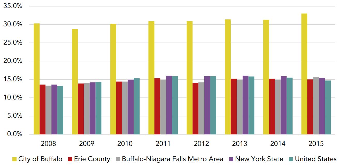
- U at B Average Household Income: $18,829
- Buffalo Average Household Income: $39,677
- U at B Poverty Rate: 44.70%
- Buffalo Poverty Rate: 28.3%
- Median Rental Costs: $1,125/month
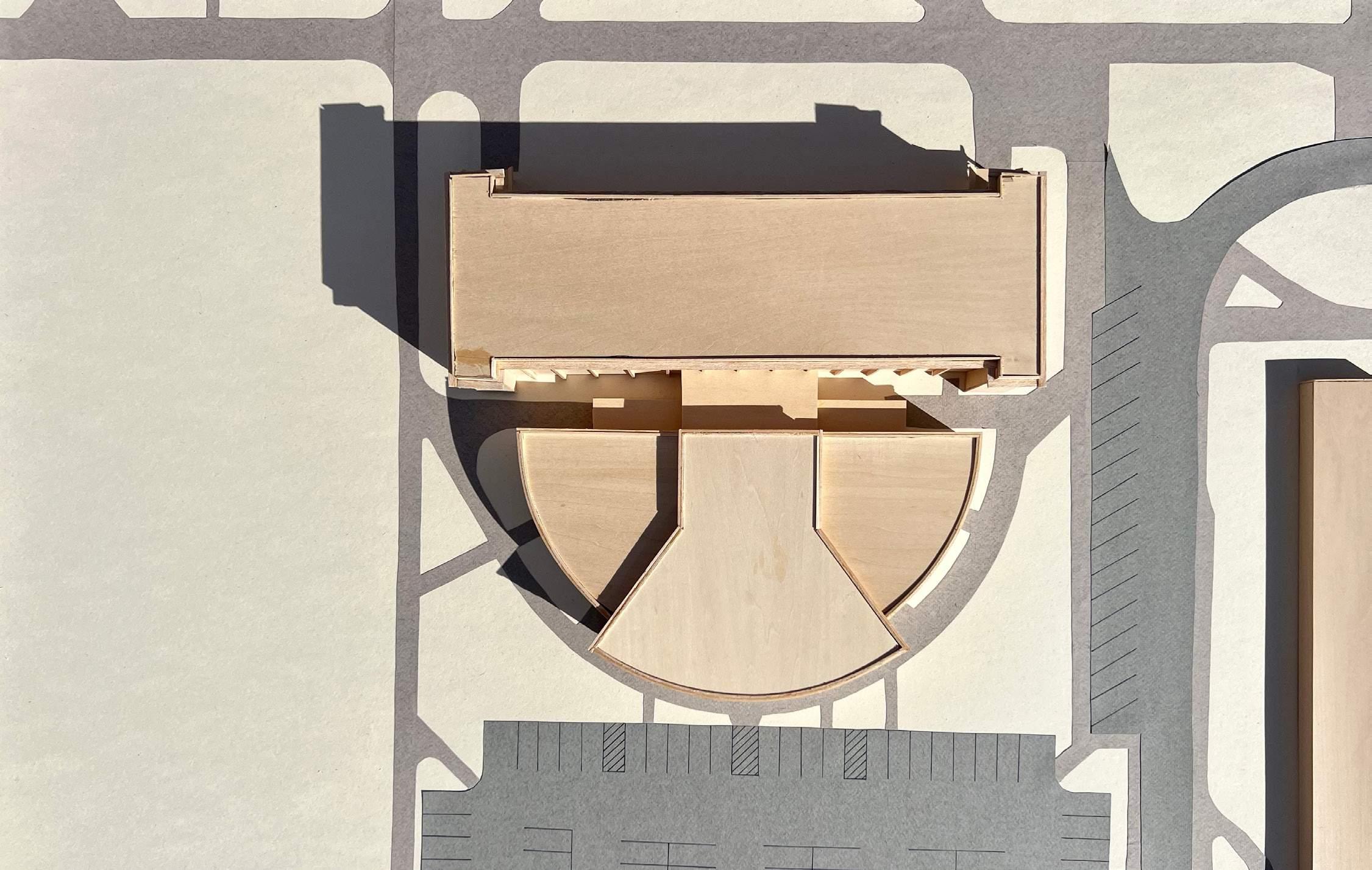
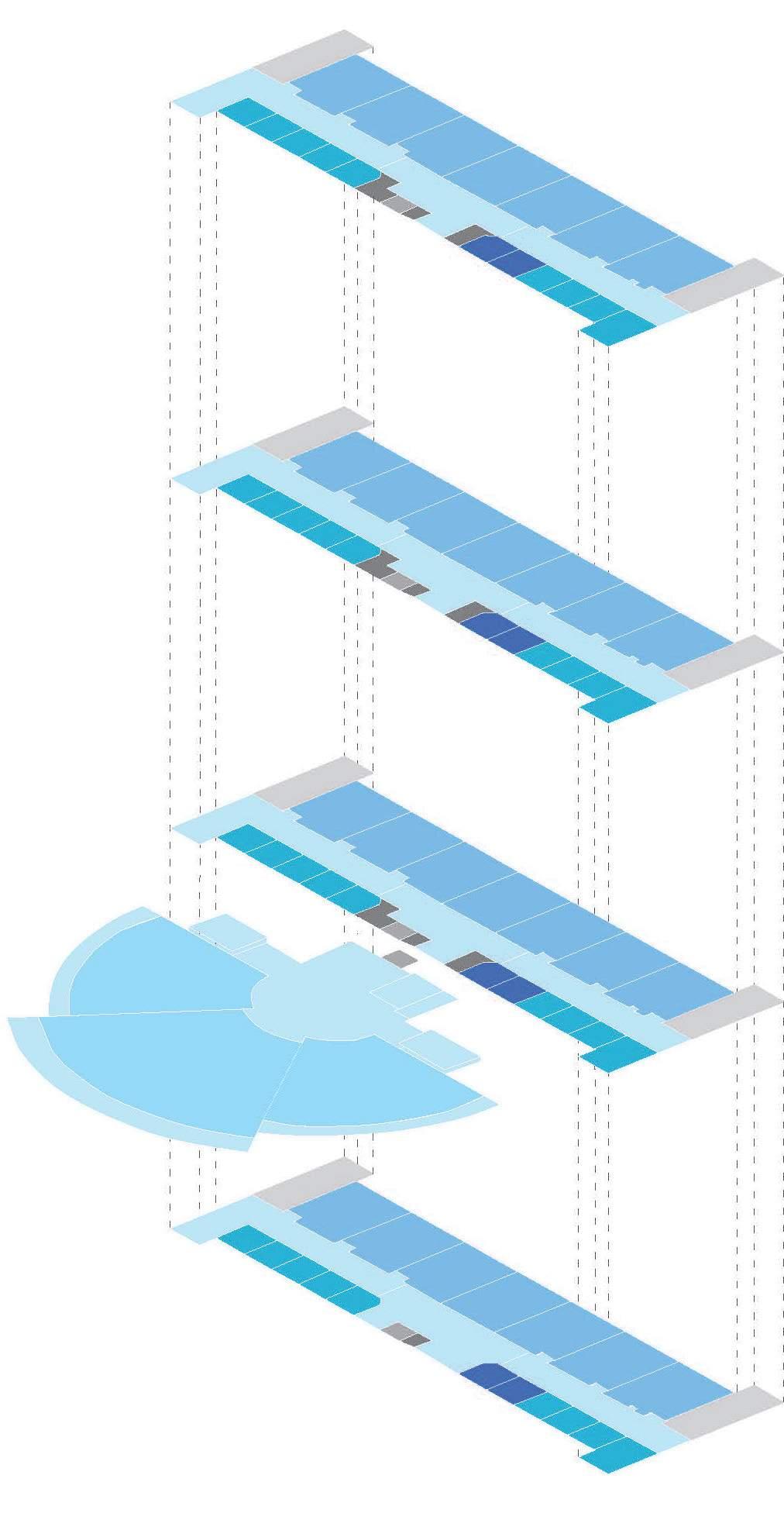
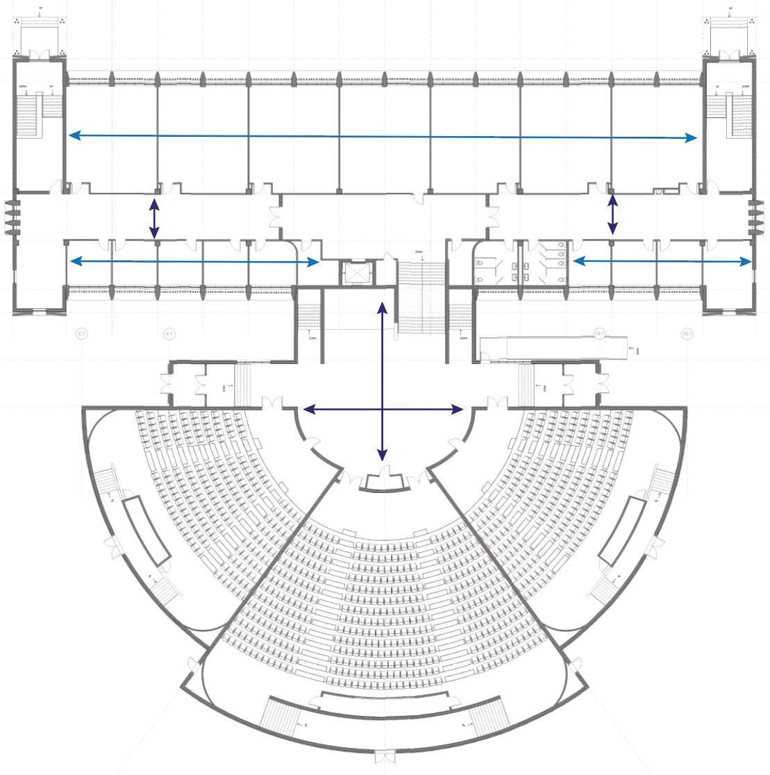
In this parti diagram, the most important thing was to connect the central axis of the lecture halls and the auditoriums. There needs to be an opportunity that enables a person to walk throughout the building without being interrupted by a set of doors or stairs. There also needs to be a unifying open space that connects all of the building program while also allowing more natural light to enter the building and increase the learning environment for the students.
The equitable access to this building has changed from being on one side of the building to all four sides. By building up the auditorium floors and ramping up to the main level of the building, someone could now easily navigate throughout no matter where they enter the building.
By opening up the central axis of this building, the program has been able to adapt to include a new cafe & library, while also providing additional break out study spaces for students. Programmatically, this update reduces the amount of unnecessarily large classrooms for smaller scale learning environments and more opportunities for students to gather and build their community outside of the classroom.
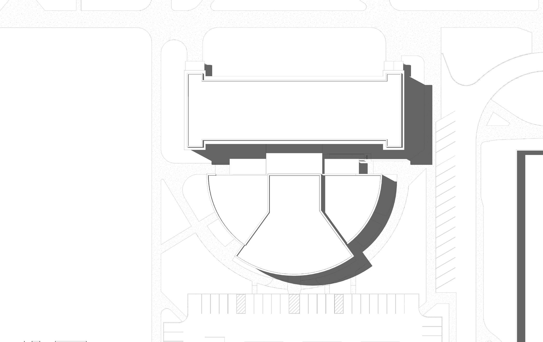
2ND FLOOR PLAN
N
A major upgrade to the building adaptation is the infill of the floor where the auditoriums where to make everything be level up entry into the
building. The corridors have more natural daylighting with the update wall layouts, and use of interior storefront. There is also going to be a
large amount of indirect light filling the entire building because of the new atrium spaces and selective removal of the concrete breeze block.
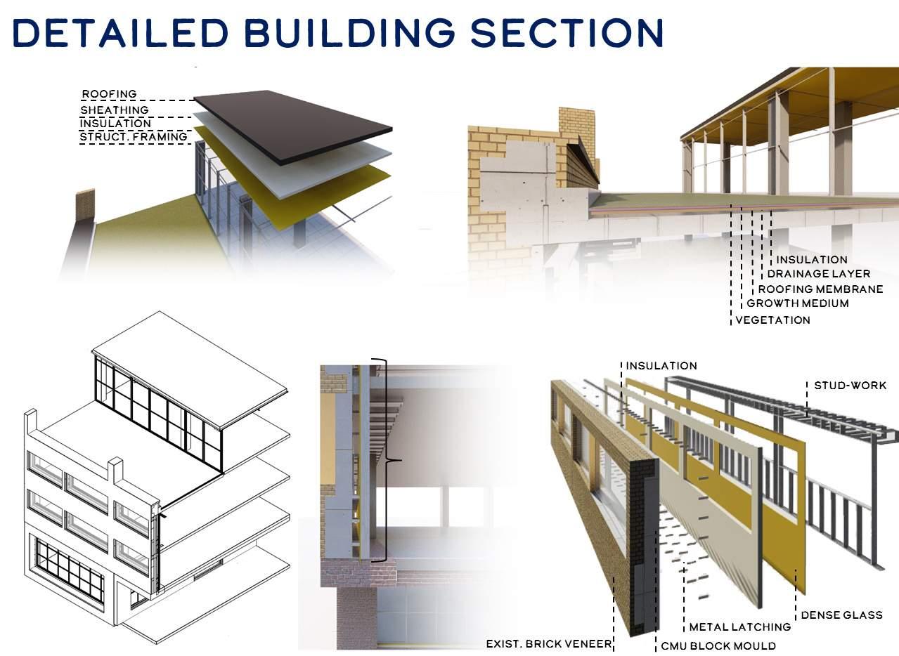
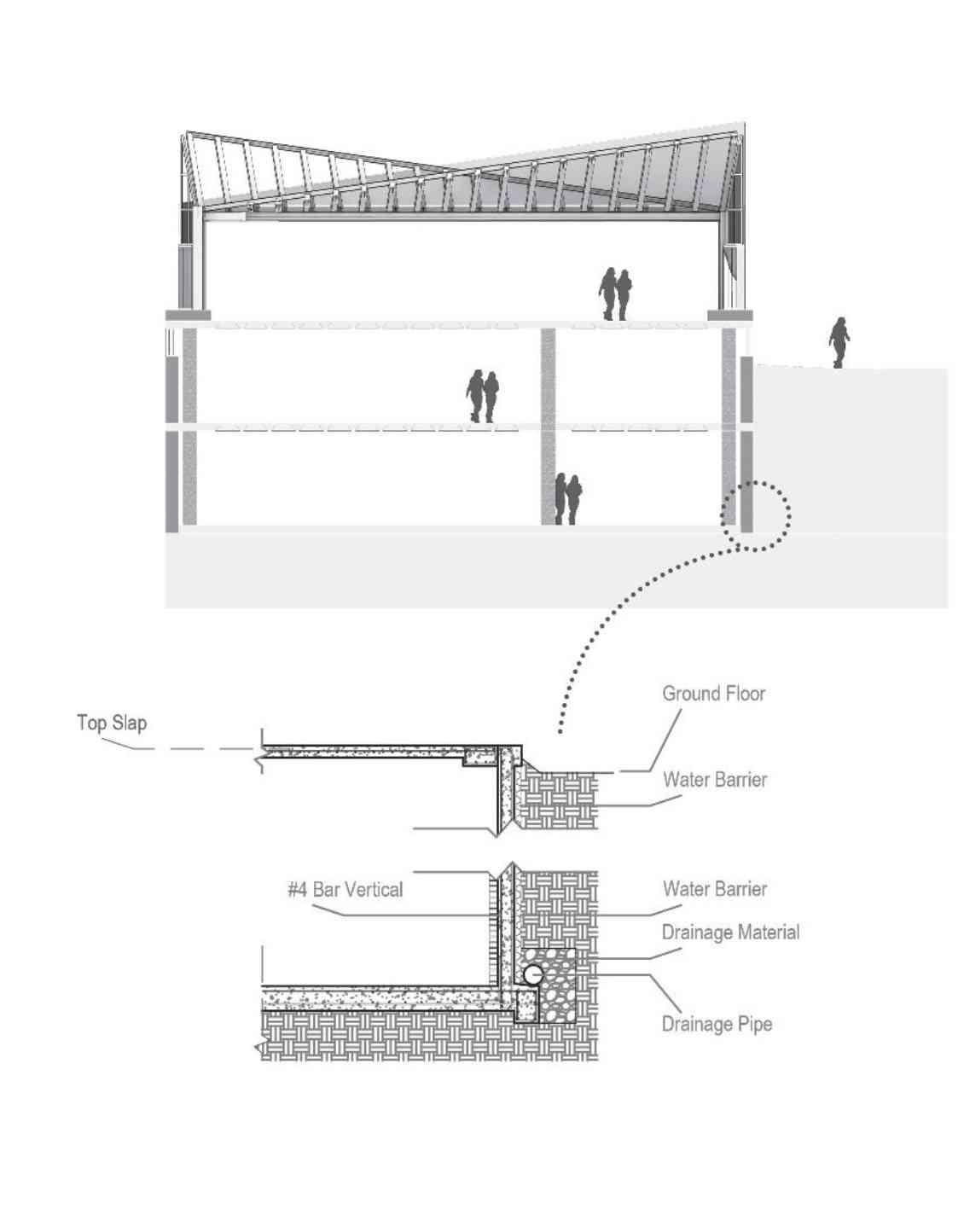
PARAPET WALL W/ COPING CAP SYSTEM & CANT STRIP AT TPO ROOF SYSTEM
BRICK VENEER, OVER MORTAR & LATHE, OVER MOISTURE BARRIER, OVER SHEATHING, OVER METAL STUD WALL W/ R-30 INSULATION
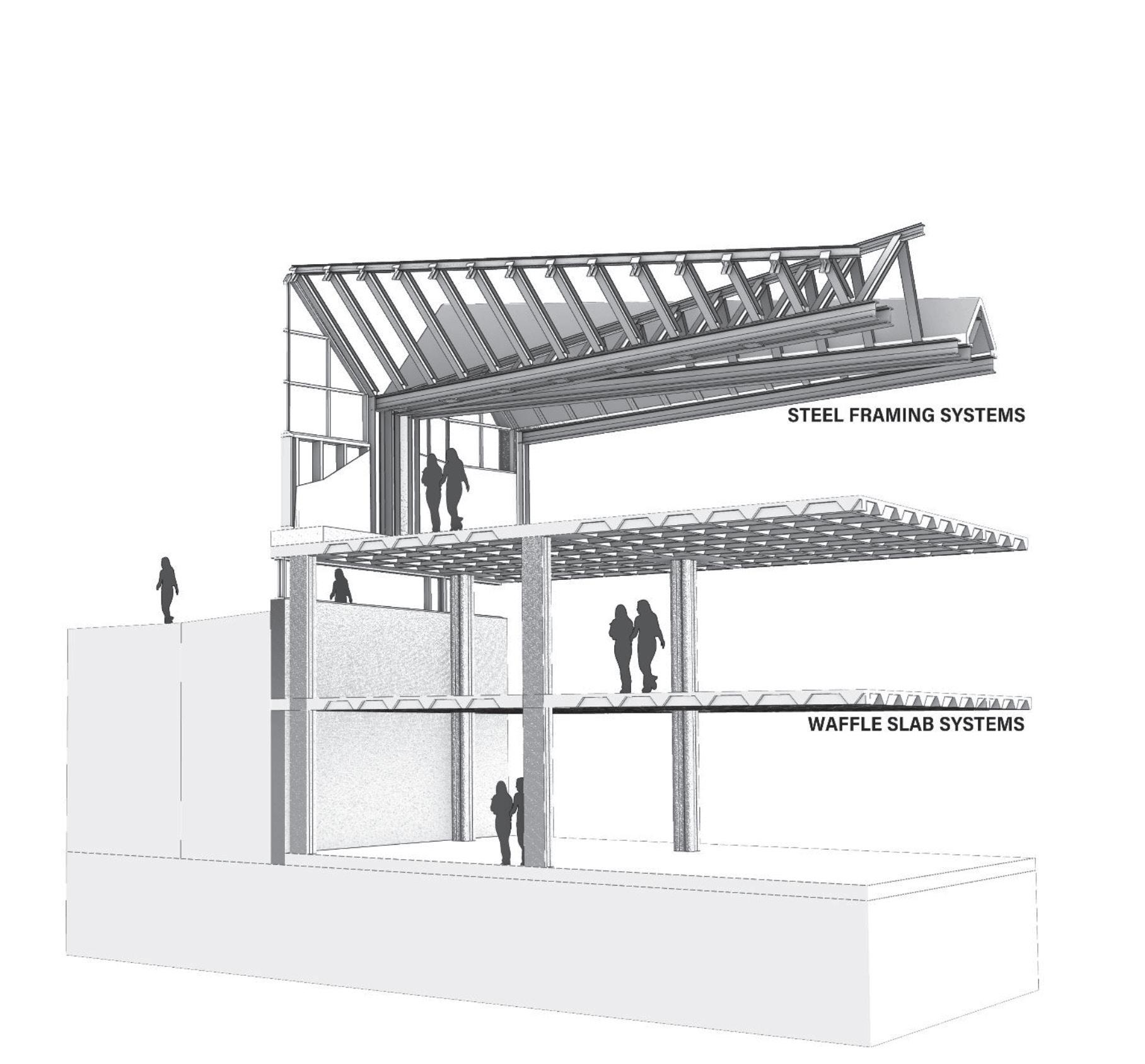
CAST-IN-PLACE CONCRETE JOISTS AND SLAB
EXISTING CMU WALL W/ BRICK VENEER & CONCRETE WAINSCOAT
WOOD FRAMED FLOOR INFILL TO BE LEVEL WITH ENTRY
The IDeA center at the University at Buffalo promotes the well being of their students. They strive to make the campus a more comfortable, safe,
and healthy place. In our design we attempted to promote the same ideas. Adding more daylight, adding a cafe, adding more collaboration space,
adding more seating, etc. All of these changes we made to our building are for the well being of the students at UB.
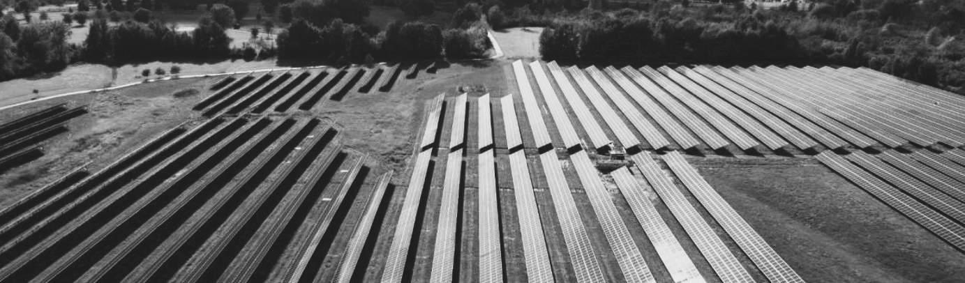
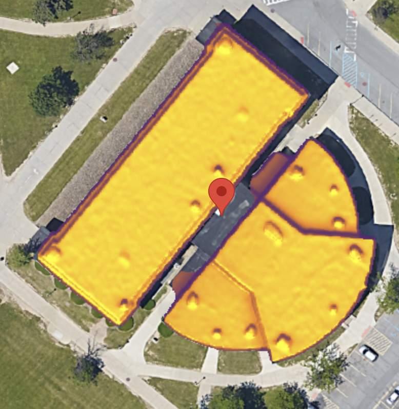
The proposed design included the building being powered sustainably. University at Buffalo has worked hard to make their carbon emmissions
zero. The solar installation size is 8.3 kW, and it will cover about 99% of our buildings electricity use. The cost of the installation is around $25,000. Total
20 year savings is around $10,000. Making this building solar powered attributes to the buildings carbon footprint.
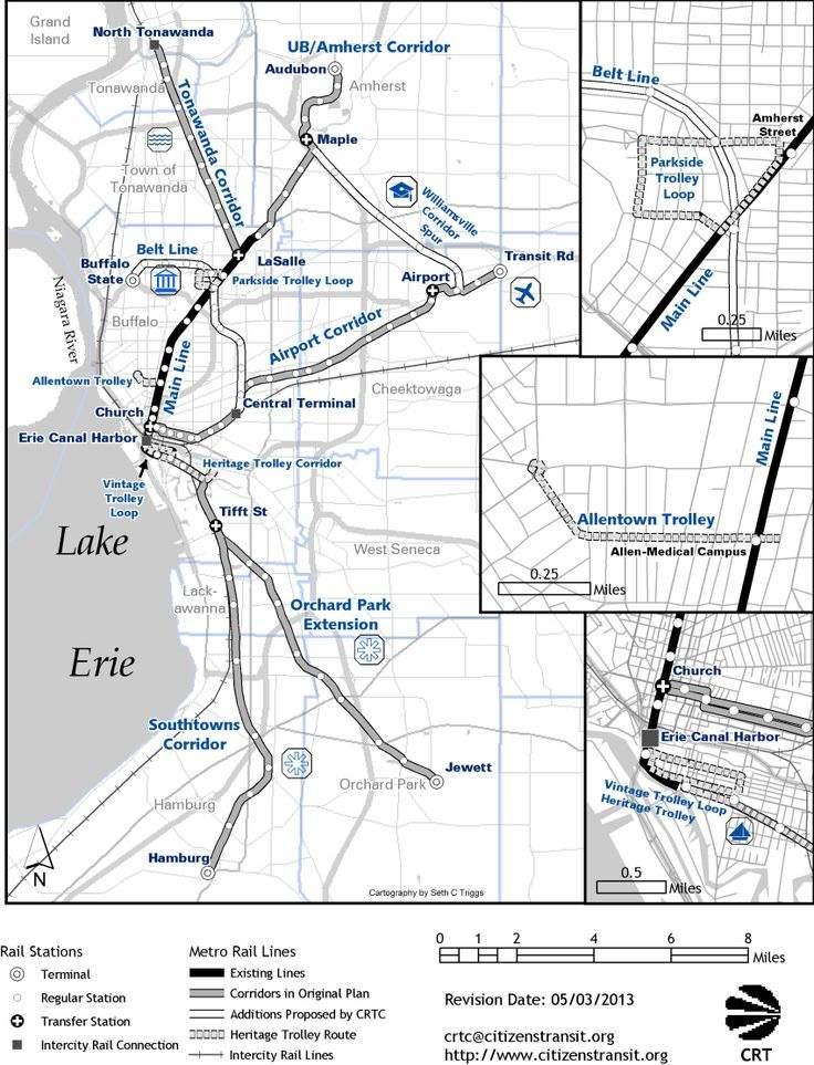
This is the transit map for Buffalo. South Campus is circled on this map. The main transit route is along Main Street with other additions proposed along that line.
This is the WalkScore for Diefendorf Hall. The building is very accessible to those who take public transit or bike. This impacted the design of the expansion as it allowed for the opportunity to have community accessible programming.