7 minute read
BIOFILM DETECTION AND MONITORING AT REAL TIME FOR COOLING WATER SYSTEM
BIOFILM DETECTION AND MONITORING AT REAL TIME FOR COOLING WATER SYSTEM
Anderson José Beber, B. Sc. Chemical Engineer, Applications Project Manager, Solenis Especialidades Químicas, Brazil
ABSTRACT
This paper describes a new methodology for real time measurement of biofilm thickness utilizing ultrasound waves on a heated surface, mimicking the heat transfer equipment on field. The ability of biofilm measurement can go as low as 5 m, which is considered very early in the biofilm formation and growth. This was applied to a large cooling system at a pulp mill which did not apply previously any biofilm monitoring.
KEYWORDS: biofilm, heat transfer, ultrasound, real time, sessile.
1. INTRODUCTION
The definition of biofilm is a loose matrix of many kinds of microorganisms that is held together with a slimy substance called extracellular polysaccharide (EPS). A significant part of biofilm is actually water. The presence of biofilm in a heat transfer surface will cause loss of efficiency, microbiological influenced corrosion under the biofilm. This can lead to a heat exchanger fail or at least lower of performance. The rate of biofilm accumulation is quite fast, being able to deposit within a few hours.
2. METHODS
2.1 Side stream ultrasound sensor
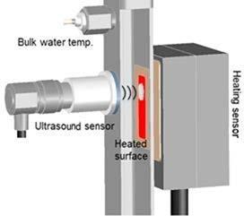
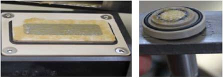
The device shown on Figure 1 can mimic critical heat exchanger conditions in real time. The device duplicates the shear stress and heat input so that the fouling factor can be measured continuously and can be compared to the design and operating conditions of any heat exchanger of interest. The device measures not only fouling factor, but also deposit thicknesses with an accuracy of +/- 5 microns. Ultrasound waves are used to measure the thickness of deposits. Figure 2 shows the heat transfer surface and the ultrasound sensor separately.
2.2 Measurement technique
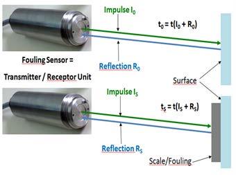
The heat transfer surface is adjusted to a given temperature range – usually 35 – 40 °C – to enhance biofilm growth. Flowrate is also adjusted to the side stream device in order to have best velocity conditions to biofilm attach on the heated surface. It is recommended to apply 15 liters per minute. The sensor sends an ultrasonic signal which goes through the water flow until it reaches the heated surface. Once it is reflected, it will reach the ultrasound sensor again. Since sound speed is known and the applied time is measured, it becomes easy to determine the extra thickness due to biofilm deposition. Figure 3
The biofilm thickness monitor and can detect biofilm growth in its initial formation to measurements as low as 5 m. Depending upon the nature of the biofilm and heat exchanger characteristics, even this low thickness can represent up to 10 – 15% heat transfer loss.
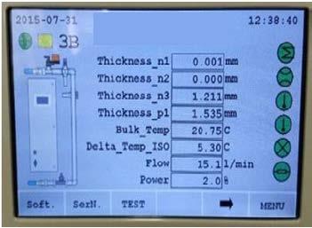
Figure 4 shows the local field human machine interface (HMI) that the equipment has for settings and measurement results.
3. RESULTS AND DISCUSSION
The ultrasonic biofilm thickness measurement device was applied to assess the conditions at an existing cooling tower at a pulp mill. Table 1 summarizes the operating parameters and microbiological control strategy.
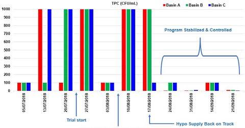
It is important to notice that prior to the addition of stabilized chloramine as a microbiological control agent, the plant used to dose sodium hypochlorite. Although this is a very common biocide, many times it is not correctly applied and may generate situations where bacteria count can be at higher than desired ranges, as shown on Figure 5. It illustrates how bacteria counts significantly dropped in comparison between before and after the oxidant biocide shift.
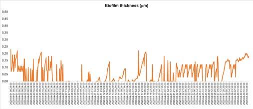
At first the biofilm thickness was considered very low and well controlled as described on Figure 6. Most of the time the biofilm thickness was kept under 25 m.
A change on stabilized chloramine dosage strategy was proposed. The total volume of biocide was kept the same. The change in strategy consisted in divide the total dosage in small batches, allowing the system to have a minimal residual of biocide for longer periods. Figure 7 shows the ultrasonic device heating surface before and after the change in biocide dosage strategy. It is quite clear the visual difference on biofilm accumulation before and after this change.
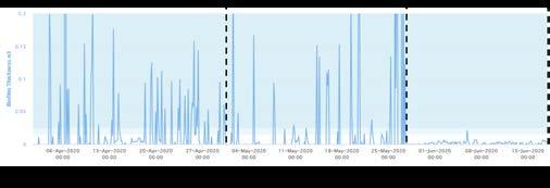
This shift on biocide dosage strategy was performed on 2 different moments. The online biofilm thickness measurement was used to identify the benefits on this decision, showing much lower thicknesses and more importantly, very low variability. Figure 8 shows the biofilm thickness drop and stability along both steps of the biocide strategy dosage change.
The corresponding heat transfer loss due to excessive biofilm accumulation was calculated on these three different periods and is illustrated on Figure 9 below. It was possible to identify an evolution on over six times less heat transfer loss due to almost not biofilm deposition on the biofilm thickness sensor.

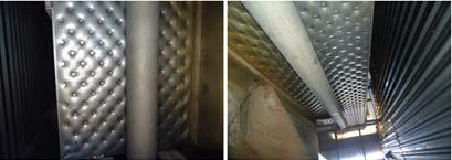
During a plant outage it was possible to inspect one of the main heat exchangers that use cooling water. Figure 10 is the internal area of this heat exchanger in its water circulation side. It is absolutely biofilm and sludge free, showing that in practice exactly was being observed with the online monitoring is real.
4. CONCLUSIONS
In summary, the biofilm thickness measurement device allowed:
• Measurements of biofilm thickness < 5 – 10 m;
• Investigation on best biocide dosage strategy with no change on total consumption;
• Reduction of heat transfer loss from 3.5% to 0.6%;
• Fewer bacteria count tests on field;
• Fewer chemical tests on field;
• Real time biofilm and slime formation;
• Cleaner and biofilm free heat exchanger surfaces observed during plant outage.
REFERENCES
2. Beardwood, E.S. “Treatment and Management for cooling Waters”, NACE International, Houston, Texas, Corrosion 2011 Conference & Expo, Paper No. 11388 (2011).
3. Beber, A. “Reduction on Water Consumption on a Cooling Tower with the Application of a Novel Biocide”, IWC International Water Conference, 16-23 (2016).
4. Bierganns, P. and Beardwood, E.S. A new and novel abiotic-biotic fouling sensor for aqueous systems, Solenis Internal Research and Development Report (2017)
5. Maurício, R.; Dias, C.J.; Jubilado, N. and Santana, F. “Biofilm thickness measurement using an ultrasound method in a liquid phase”, Environ Monit Assess, 185(10):8125-33. doi: 10.1007/s10661013-3160-0 (2013).
6. Seida, F.; Flocken, C.; Poschmann, R.; Schultz, M.; Klaua, R. and Dietrich, G. “Method and Device for High Precision Measurement of a Characteristic of a Fouling and / or Scaling Deposit Inside a Fluid Vessel or a Characteristic of a Portion of the Wall Inside a Fluid Vessel by Using Ultrasound”, International Patent Publication, Number WO 2009/141135 A1 (2009).


