
9 minute read
AutoCAD Civil 3D

from AUGIWorld
by AUGI, Inc.

PRODUCT FOCUS AutoCAD Civil 3D
Autodesk Civil 3D 2021 - Survey Tools
Well, since this is the Salary Survey edition of the magazine, I thought it was fitting to review some “Survey” tools! After all, most projects begin and end with survey, but I feelx like it gets often overlooked in Civil 3D. That joke goes over much better with the survey audience. But I love working with GIS data on all my projects as well. I typically do not begin a project without using some sort of GIS data in addition to the survey data.
So here is some survey related tools I use on almost every project.
GIS DATA
By far my favorite command in Civil 3D is MAPWSPACE!! One simple command can open the portal to utilizing the power of GIS data. You could change your Civil 3D workspace to the Planning and Analysis tab, but this gets you started with using the GIS data.
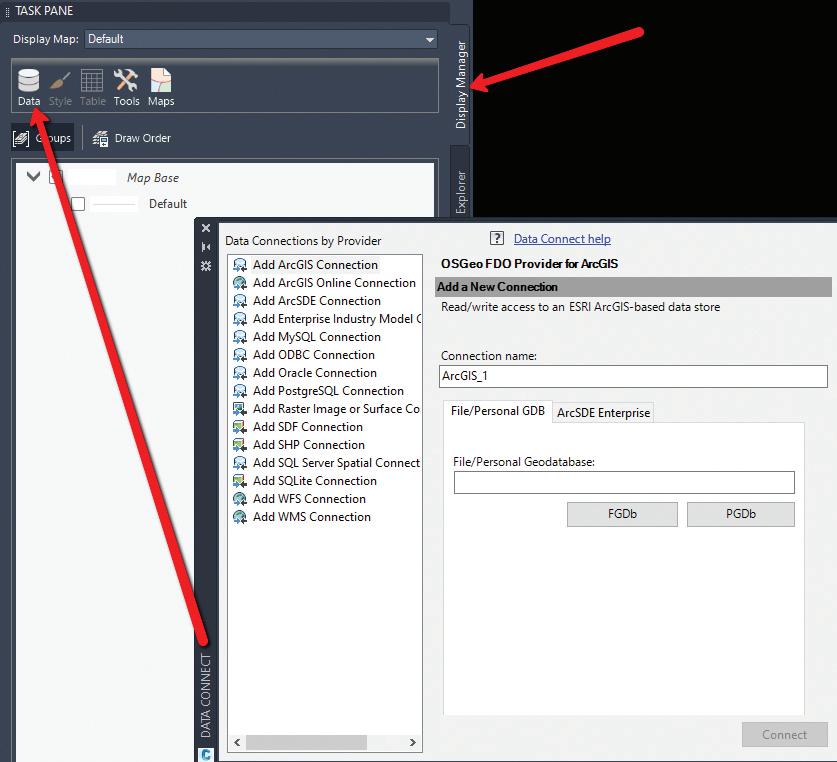
Once you type in MAPWSPACE, you then turn on the Map Task Pane. The Task Pane gives you quick access to frequently used features, and groups these features into taskrelated views. Use the Task Pane to create, manage, display, and publish maps. You will notice 4 tabs; in this case we will focus on the Display Manager.
In the Display Manager, you can simply select the DATA icon and connect to numerous data sources! Here you can import shapefiles, connect to external databases, and even bring in imagery. Did you know you can simply select your shapefile from Windows Explorer and drag and drop it on your screen? By far the easiest way to import GIS data!! Once dragged onto your screen, the layer will show in the task pane where you can query, theme, style, label and access all the attribute data within the DBF file. If your coordinate system is set, it will project to the correct location, or re-project as needed.
TIP: Need to do a quick concept plan? Drag and drop your parcel shapefile, select the property you wish to use, rightclick, check out feature and explode!! This creates a polyline that you can then utilize the parcel features on. And if your
CAD manager asks who told you to explode something in
Civil 3D….it wasn’t me!
Select the entire layer from the Task Pane, or even a feature from within model space, right-click and choose SHOW DATA TABLE. This will display all attributes for that selected feature.
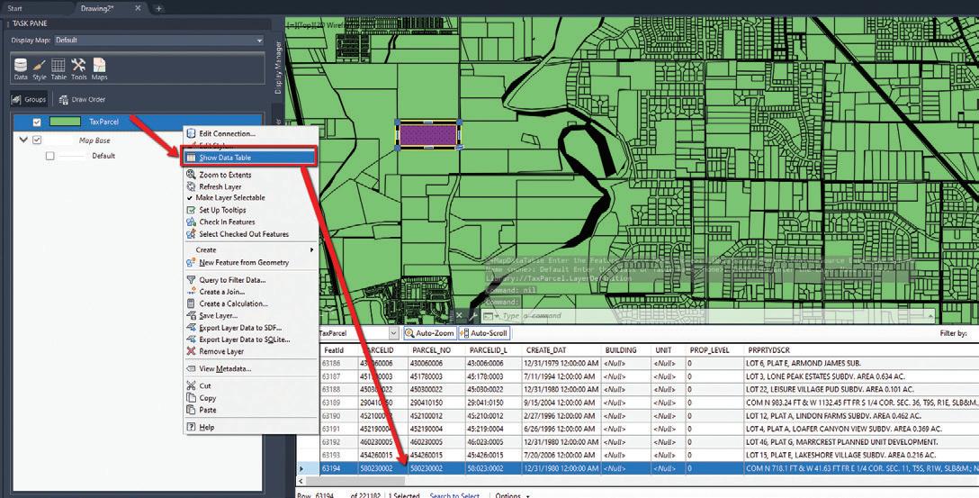
Right-click again on the layer from the Task Pane, you can perform all sorts of analysis and creation tasks right from here. Want to label and change the display? Simply select Edit Style.
In the Style Editor, you can perform many helpful tasks. You could, for example, theme the parcel shapefile and look for all parcels between 5-10 acres. This works great for soil types, utility line sizes and many other uses. You could also edit the style (hatch pattern/ polyline) as well as add a label based on the feature attributes.
All this from dragging and dropping a shapefile and using the Task Pane! All without switching workspaces and great for just getting
started with GIS data.

QGIS
We are working with larger data than ever before. Drone data and aerial imagery is now at the tips of our fingers anytime we want them. Some raster images can be many GB in size and resolution that Civil 3D cannot handle. If you have ever tried to import a GeoTiff (or other image types), and you get the “Invalid Image” warning, then QGIS is exactly what you need!
This is a FREE open source software tool that allows you to reduce the size of large images quickly and easily, and even translate to other coordinate systems if you’d like. Just go to www.qgis.org and download it.
You simply drag and drop your image into the QGIS desktop, rightclick on your layer (image) and export to a new rendered image!!
TRAVERSE EDITOR
Recreating deeds has always been a long, time consuming process. Drawing geometry line by line, arc by arc, can get a little bit boring and mistakes can easily creep in. But there are 2 options in Civil 3D that can help on this task. There is the COGO Editor and Traverse Editor. I will review the Traverse Editor below.
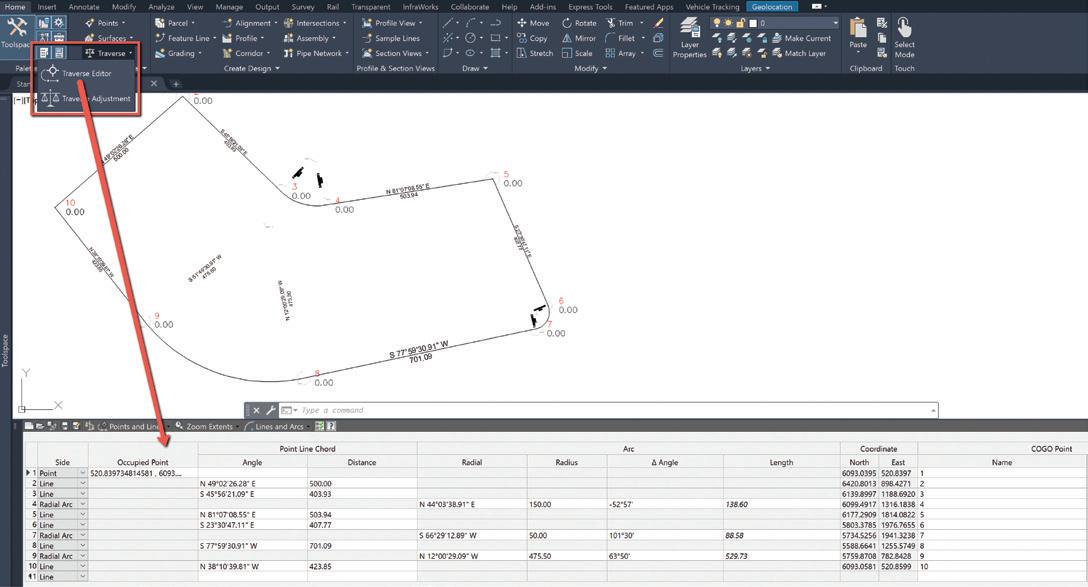
Traverse Editor
• You can use this to create 2D traverses by either selecting a polyline, or typically by entering deed data in the dialog box. You can specify whether you want to create points, lines, or points and lines in the drawing as you enter data. These objects remain in the drawing after you close the Traverse Editor. And for longer deeds, you can save your entry data and come back at a later time if needed. • You can enter traverse data in the Traverse Editor by creating traverse sides. Side types can be Point, Line, Chord Arc, Radial Arc, or Side Shot. The first entry must be a point of beginning (POB).
WRITING LEGAL DESCRIPTIONS
The Reports Manager from within the Toolbox has some great reporting tools. Out of the box they work great, and with a little customization you can end up saving a ton of time. The first thing I do prior to running a parcel report is set the point of beginning. That way your legal descriptions come out in the right order and you spend less time editing. Note: You must use parcels for this workflow, so if you need a legal description, simply turn your linework into a parcel, or parcels.
Setting your POB
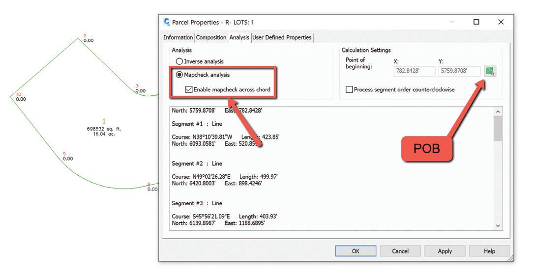
• Select the parcel you want to create a legal description for, rightclick and go to Parcel Properties. • Change to the ANALYSIS tab. • In the upper right, under Calculation settings, you can change the Point of Beginning by selecting the green box and selecting the points from within your drawing.
Need error of closure data? You can also perform a Mapcheck Analysis right here in the same screen!
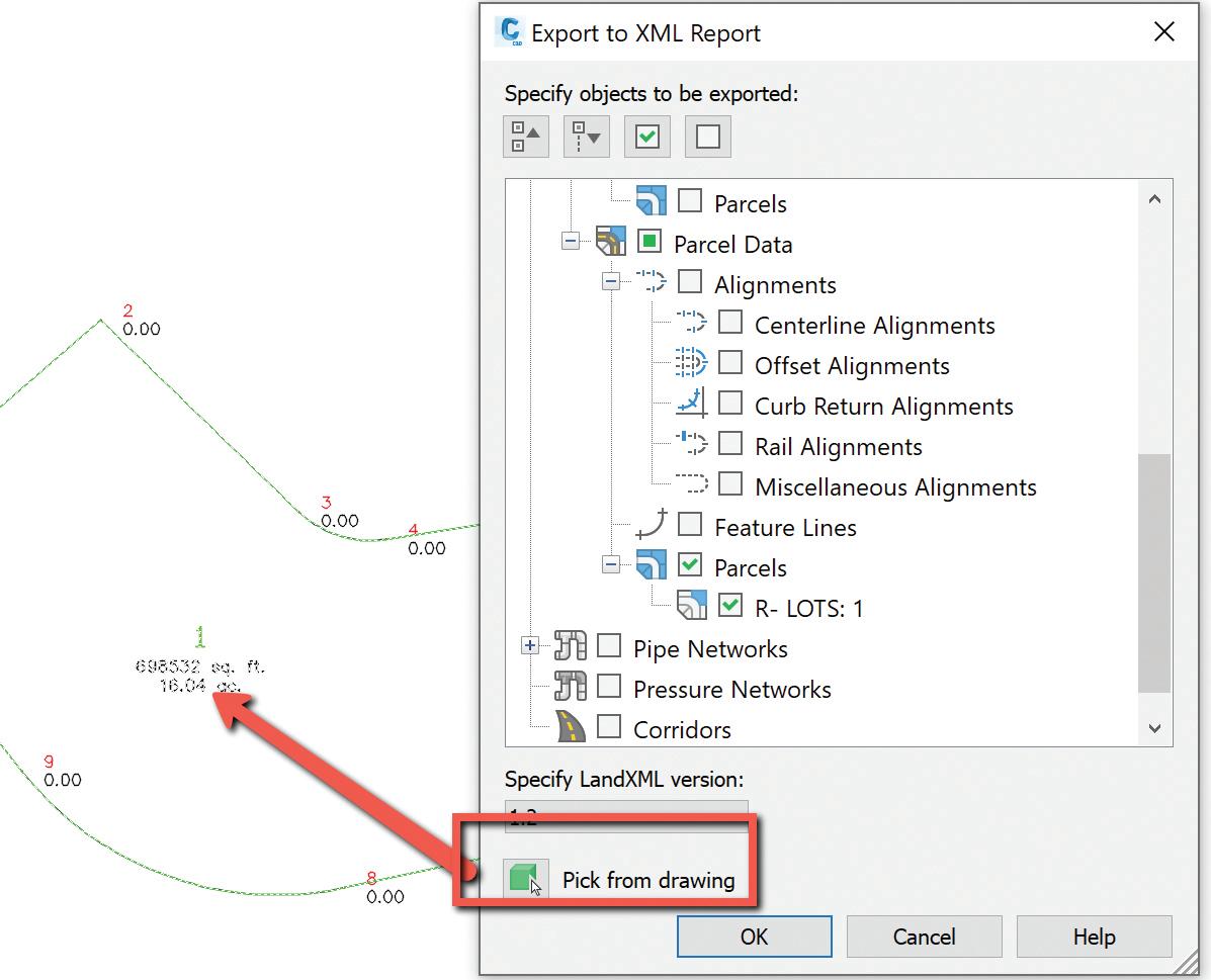
Parcel Reports
• Once you have set your POB, switch to the Toolbox tab of your
Toolspace. • Expand Reports Manager and expand Parcels. • There are several options to choose from. On either option you can select the option, right-click and choose Execute. • Use the Pick from Drawing option on the bottom left. You must select the Parcel Area Label itself, not the linework. You can select multiple, or one single parcel also. • Select OK • The description will open in a browser, although sometimes formatted weird, and then you can copy and paste into
AutoCAD as MTEXT (or word/email).
MAPCHECK ANALYSIS
You can use the Mapcheck Analysis command to perform a mapcheck that is based on the precision of your label. This can be a line/curve label or parcels labels. It will read the direction of your bearing call (NW v/s SE, etc.) so ensure that they are labeled correctly.
Type in MAPCHECK to launch the analysis or find it from the Ribbon on the Analyze tab, to the far left under Survey.
To perform a mapcheck you must specify a point of beginning (POB) for each parcel. For each segment within the parcel, you select a label containing a direction, direction and distance, distance label, or curve label until the requirements to compute the next vertex of the current segment are met.
As you perform a mapcheck, selecting label by label, temporary graphics are displayed in the drawing to indicate the sides that have been entered for each parcel. The current side is displayed in bold indicating origin and direction for that side. The temporary graphics also provide a visual confirmation of possible errors or indicate that the direction of a line or curve needs to be flipped or reversed.

PROJECTING OBJECTS TO PROFILE (OR SECTION) VIEWS
Projecting points into your profile and sections can really help in design and displaying existing features. Take an existing high-pressure gas main for example. You may have gone out to pot hole a main at some point, and need to show that in profile view to ensure no utility crossings conflict. So, importing your points, and projecting those to your profile is very simple. You can project points, feature lines, blocks, and all sorts of objects to your profile.
Project Objects to Profile
• First, import your points. • Select the Profile View you want to project your points into. • From the Ribbon, on the Launch Pad panel, select Project
Objects to Profile View • Select the point, or multiple points, that you want to project. The dialog box will the appear where you can set object and label styles. • This will project based on the point elevation, so if you shot top of pipe, it will appear at the top of pipe elevation. (Unless you change to other options). • Select OK and your object is now shown and labeled in your profile view.

PARCEL PROPERTIES MANAGER
Have you ever used this before? Well neither have I until just a couple weeks ago. This is a pretty quick way to globally change parcel styles and area label styles, without going in one-by-one. You can also add info to the description of each individual parcel. I use the description field a lot in plats, whether for addresses, tax ID numbers or simple notes.
In addition, you can also export a list of parcels to a CSV file for use in other applications, such as other GIS platforms. The list can also be used as the basis of AutoCAD tables and text objects within the drawing.
This tool can be found under the Miscellaneous Tools on the Toolbox. Give it a shot and see what you think!
CONCLUSION
Yes, I have skipped the obvious “Field to Finish” workflows for now. By now people have decided whether they want to use that or not, so I focused on a few other tools that help me in day to day project workflows. In an upcoming article I will detail the setup and workflows needed to perform the automated linework, or Field to Finish options.
I would love to hear from you regarding the survey tools you use and any tips or tricks you have, as well as feature requests for survey. So, feel free to call or email me anytime.
Shawn has been a part of the design engineering community for roughly 15 years in all aspects of design, construction, and software implementations. He has implemented and trained companies across the Country on Civil 3D and other infrastructure tools and their best practice workflows. Shawn can be reached for comments or questions at sherring@prosoftnet.com.
