8 minute read
Civil 3D
from AUGIWORLD
by AUGI, Inc.
Geotechnical Modeler
INTRODUCTION
When I finished last month’s article in AUGIWorld on the Geotechnical Module, Autodesk was working behind the scenes on a new version of capturing geotechnical data in Civil 3D. On February 9 of this year Autodesk released the Geotechnical Modeler for Civil 3D 2022. The Autodesk Geotechnical Modeler is a Civil 3D extension which enables you to visualize and analyze your geotechnical data directly within the Civil 3D drawing environment. Now that you have knowledge of the Geotechnical Module let’s explore the Modeler and the capabilities it can provide for producing geotechnical BIM within Civil 3D.
AUTODESK INTRODUCES GEOTECHNICAL MODELER

The Geotechnical Modeler for Civil 3D is an add-on extension that can be installed for Civil 3D 2022 and available through the desktop app or within your Autodesk account. After installing you will see a Ribbon tab named Geotechnical Modeler as shown in Figure 1.
The goal of the modeler is to produce geotechnical data derived from a spreadsheet with the ability to update in Civil 3D.
SAMPLE DATASET FILES
The Geotechnical Modeler includes a sample geotechnical project as shown in Figure 2 which users can quickly explore the subsurface modelling and visualization tools. There are two formats of the same project file. The first dataset is in AGS 4.0 format with the filename “GM-Sample Project.ags”. The second dataset is in CSV with the standard file naming convention: “Location Details.csv”, “Field Geological Descriptions.csv”, and “Orientation and Inclination”. Use these files to test out using the module and watch how it inserts the data into your current drawing. You need to keep the format the same as the examples including the headers and columns, do not delete and/ or replace even if there is no data in the column.
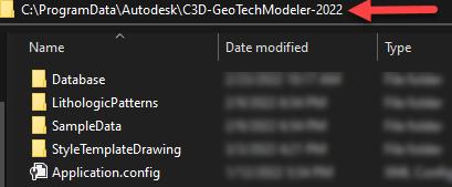
Figure 2: Sample Data Location
MANAGING YOUR DATA
We first need to look at our data and make sure it is in the correct format for importing. For this example, we will focus on the .xls format of the files. Review the headers of the sample .xls file and input your data into that file and keep all the files within the same folder.
The first file is the Location Details.csv. This file is straight forward with an ID, Type, Easting, Northing, Ground Level and Final depth as shown in Figure 3.

Figure 3: Location Details.csv
The second file shown in Figure 4 is the field descriptions.csv. This file has a few more columns that we need to pay attention to but remember we don’t need to use all the columns. I broke this up into two vertical images to display the fields. Remember, you Location ID must match what is on your location details.csv for the data to be interpreted.
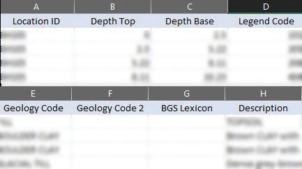
Figure 4: Field Descriptons.csv
We need to take our borehole data and paste into the correct fields within those two files, then we are ready to import as shown in Figure 5. Manage data and follow these 5 steps.
1. Create a project 2. Enter the project and drawing coordinate system. 3. Import the Borehole data 4. Add boreholes to drawing 5. Close the Manage Borehole data dialog.
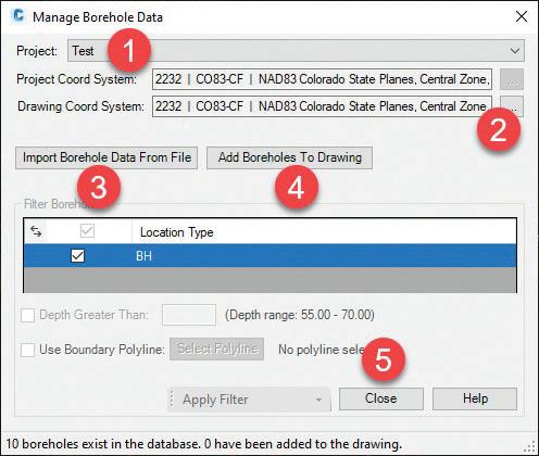
Figure 5: Manage Borehole Data
After selecting add borings then closing your borings will be displayed as COGO points within your Civil 3D drawing as shown in Figure 6.
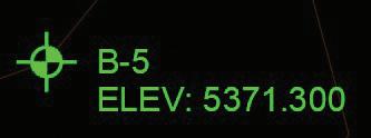
Figure 6: COGO Points
The first thing you may ask is, “What style does the modeler use to import these borings?” On our spreadsheet we used the Location Type field to identify a Civil 3D Cogo point which the style of the point is defined by using an AutoCAD block. Located in the samples folder there are two .dwt files which contain the blocks used for importing data. Open the GM_Styles (Imperial).dwt file and look at the data that is contained within that template. Figure 7 shows the styles in the drawing
and the blocks that are contained in that file. We used the block BH which uses the BM-LOCA-B2 block to define the COGO point style. COGO points are Coordinate Geometry points in Civil 3D. If you are not familiar with COGO points look in the help menu to gain more knowledge on how these are created within Civil 3D.

Figure 7: GM_Styles Template Drawing
BUILD STRATUM SURFACE AND SURFACE DISPLAY
Depending on how your geology is setup in the Field descriptions.csv file you can build surfaces from that data. Select the Build Stratum Surfaces Box on the Ribbon as shown in Figure 8.

Figure 8: Build and Display on the Ribbon
Notice how the Legend Code has 43 values. That is the field within the excel file that lists the separate types of geology and the depth for each stratum. Select Build Surface as shown in Figure 9 and your surfaces will automatically be built and show up in the prospector tab.
The Stratum Surface Display button is an easy way for you to display the styles of your surface within an easy-to-use dialog box. Select what you would like to display then apply the settings.


Figure 10: Surface Stratum Display
CREATING SUBSURFACE PROFILES
Creating subsurface profiles has become easier with the geotechnical modeler. Create an alignment within your drawing as you would normally do within Civil 3D. Select Subsurface Profiles on the geotechnical modeler tab on the ribbon. You will now have a dialog box as shown in Figure 11. Follow the steps to create your profile view with geotechnical information.
1. Select your alignment 2. Give your profile view a name. 3. Select the surface to display as well as the
Geology field. 4. Select the boreholes which you would like to view on the profile. (Keep in mind if they are offset from the alignment the strata may not line up exactly on the profile view). 5. The settings of the and labels of the sticks.
Change these values to get an optimal display of your profile. 6. Select Create Subsurface profile.
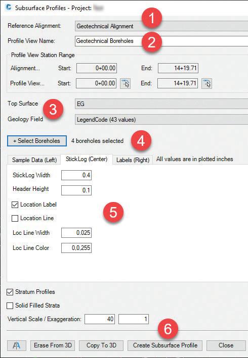
Figure 11: Subsurface Profile Data
In the Subsurface Profiles dialog box as shown in Figure 11 you can adjust your sample data on the left, center, and right by selecting each of the tabs shown in Step 5. If you adjust your data and want to update your profile, you will go back to this same dialog box and select the Update Subsurface Profile shown in Step 9.
7. Erase from 3D 8. Copy to 3D 9. Update Surface Profile

Figure 12: Updating your profiles
The Copy to 3D and Erase from 3D tabs will update the boreholes in 3D. A good workflow is to Copy to 3D then Erase from 3D if you need to update. After you are comfortable with your selections create the profile view just as you would in Civil 3D. Select an area on the screen for your profile view to be displayed as shown in Figure 13. Notice how the boreholes are displayed with hatch patterns and strata lines which are controlled by the surfaces you created.

Figure 13: Geotechnical Profile
2D STICKLOGS AND 3D BOREHOLES
You can also display 2D boring sticks, 3D boreholes, and Export 3D data. The 2D boring sticks and 3D boreholes are straight forward. Select the 2D sticklogs on the ribbon and follow the instructions as shown in Figure 14.
1. Select the Geology Field 2. Enter display data for your borehole 3. Depth Labels
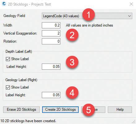
4. Geology Labels 5. Create the 2D Sticklogs
The (10) 2D sticks have been created and placed as a block at the COGO point location. You can erase the sticklogs by selecting the Erase 2D sticklogs button.
INFRAWORKS
When Selecting the Export 3D data, you will have the option to export the surface strata as well as the 3D boreholes. Good workflow is to keep the boreholes in a separate file. Use the 3D exported drawing and import into Infraworks to get a visual display of your borings along with a map from Model Builder.
Figure 15: 2D Borehole
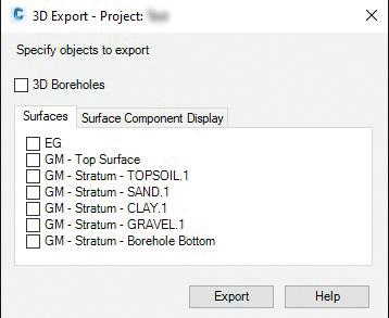
Figure 16: Exporting 3D Data to Infraworks
CONCLUSION
With the introduction of the Geotechnical Modeler Autodesk provides us another way to display Geotechnical data within our designs. All these methods are helping improve our ability to design accurately and display data in a visual style that is appealing to our customers and clients. For more information on the geotechnical modeler see Autodesk’s website.
https://help.autodesk.com/view/CIV3D/2022/ ENU/?guid=Civil3D_GeoTech_What_Is_the_ Geotechnical_Modeller_html
When using the modeler there are various ways to customize your visual display as well as your hatch patterns. Editing the hatch patterns is as easy as defining your new patterns within the Geologyhatchstyle.config file in the samples folder and as shown in Figure 17. Use Notepad or a text editor to add the patten definitions to your file.
Explore the examples and take your geotechnical data to the next level where you can use and implement the geotechnical modeler add-on for Civil 3D 2022.
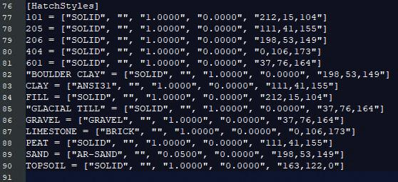
Figure 17: Editing Hatch Patterns
Sam Lucido is a Design Systems Administrator for CHA Consulting, Inc. He has over 25 years of experience in engineering design projects, user support, CAD standards and customization. Sam is professionally certified in AutoCAD, Civil 3D, and an Autodesk Expert Elite Member. Sam has been a top-rated Autodesk University Speaker for the past 7 years and created many articles on AutoCAD and Civil 3D through the Autodesk Knowledge Network. He uses his vast knowledge about AutoCAD and Civil 3D to help provide support to engineering and design teams at CHA Consulting, Inc. You can find him at CADProTips.com and he can also be reached at sam.lucido@cadprotips.com


