
5 minute read
Voltage drop circuit testing –Part


Two
This is the second article on voltage drop circuit testing, following on from the basics and fundamentals of the circuit testing methods explained in the June issue.
You need to have the correct tools and equipment in place to test and diagnose electrical faults – a good digital multimeter is essential to trace faults and give you accurate test results, don't buy a cheap multimeter as a good quality one will last for years if you look after it.
Below is a reminder of the rules that were explained in my previous article:
Rule 1
A digital voltmeter displays the difference in voltage between where you place the black probe and to where you place the red probe
Rule 2
The voltage after the last resistance in a circuit will always be zero (providing current can flow)
Rule 3
Volt drop will only occur across a resistance if current can flow
Rule 4
The Volt drop across a resistance in a series circuit is in direct proportion to the comparative resistance’s values.
By Des Davies AAE MIMI, Top Gear Motor Services
This basically means that voltage drop across all the resistors in that circuit must add up to the source voltage e.g. If you measure a 12V drop across the battery terminals, then with 1 or more resistors in that circuit they should all individually add up to the 12V system voltage. In a 3-resistor circuit, if they have all equal resistance then the voltage drop across the individual resistors will be 4V, each adding up to 12V system voltage, and this is Ohm’s law.
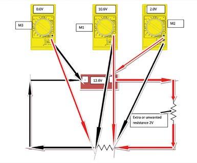
Place your multimeter across the positive/live circuit to check for the voltage drop in the circuit, in this case, an unwanted resistance was found in the positive/live side of the circuit. The M3 multimeter on the left, Figure 1, displays 0V indicating a good ground/earth. M1 in the centre displays 10.6V, the system/battery voltage is 12.6V, therefore we have an unwanted voltage drop of 2V somewhere in the circuit, check this using M2 to confirm this part of the circuit has the unwanted resistance. Place your multimeter M2 across the positive live circuit to check for a voltage drop, in this case, an unwanted resistance of 2V was found in the positive live side of the circuit. To check the positive/live side of the circuit place the red multimeter lead of M2 on the battery positive post and place the black multimeter lead to the main resistor input. If the reading is the same reading of 2V as indicated by the right hand side multimeter M2, then keep the red lead on the battery positive post and place the black lead at different points in the circuit working backwards towards the battery positive post until this multimeter reads 0V (0.5V max). Between the previous readings of the multimeter of 2V and 0V-0.5V is the unwanted resistance in that circuit. When you locate and repair the fault, place your multimeter M2 across the positive/live circuit, red lead to battery live/+ post and the black lead to the input terminal of the resistor to confirm and check for the voltage drop in the circuit. This should now display a reading of 0V (0.5V max) indicating a good positive live side part of the circuit.
A good way to check your ground/earth circuit is to reverse the leads – place the red lead of the multimeter to the positive terminal connector on the battery and the black lead to the negative ground/earth side of the resistor/component. This should display a reading of the battery/source voltage, in this case 12.6V which indicates a good ground circuit going back to the battery/source. Note, the multimeter may display a minus figure because the meter leads are reversed, this is normal.
If I am probing a lead in any part of the positive side of the circuit, which has a 12V supply, then either side of these 2 probes will have a 12V supply, therefore the meter reads 0V, because there is no difference between 12V and 12V so there will be no voltage drop in that cable and that part of the circuit is good, 0V. The maximum reading you should have on your multimeter is 0.5V if the positive or live side of the circuit is operating correctly.
The black lead is connected to the battery negative terminal and the red lead connected to the component/resistors earth/ ground lead. This meter displays 3.0V on the ground side, indicating that you have a poor ground connection in this part of the circuit, we now need to test this part of the circuit to locate the unwanted resistance.
The same is said if I probe the ground side cable using my 2 leads then either side of the probed leads should have 0V, and there is no difference in the voltage readings therefore the meter reads 0V, no voltage drop. The maximum reading you should have on your multimeter for a 12V circuit is 0.5V if the ground or earth side of the circuit is operating correctly.
You will now need to move your red probe back towards the battery ground until your meter now reads, for example, 0V (Meter2). In between the 0V reading that you have just recorded and the last probed reading of 3.0V (Meter1) is the high resistance in the circuit causing the malfunction in the circuit.
The black lead is connected to battery negative terminal and the red lead connected to the resistor input terminal with a perfect 0V reading, indicating an open circuit in the positive/ live side of the circuit and no current flow. Note: A 0V reading on your meter can also indicate a short circuit or very high resistance in that circuit and the meter will not register any reading, please be aware of this.
These testing methods can be used on any 12V circuits on the vehicle e.g. Starting, lighting, wiper/washer, engine management sensors and ABS etc for the correct functionality of that system.

Having the correct knowledge of how the circuits operate correctly is essential, and having a good reliable source of technical information and the manufacturer's data and circuit diagrams will help you to diagnose the electrical faults and help you fix the vehicle.
There are plenty of good quality electrical test equipment out there but I was always told as an apprentice, look after your tools and your tools will look after you! That tends to be good practice.
Remember the best tool you have in your possession is between your ears, this does not cost anything, so use it to its full potential!
Visual checks are essential to help you to locate problems and faults such as heat, burn marks and green crusties etc.
The black lead is connected to the battery negative post and the red lead connected to the earth/ground side of the resistor. A 12.6V reading on the multimeter indicates an open circuit in the earth/ground side and no current flow in that circuit.
Many technicians that I speak with struggle with electrical fault finding and tend to send the work out to other garages or mobile repair technicians. It can be time-consuming but also very rewarding when you locate the faults in these systems.
Electrical fault finding and diagnostics can be difficult at times but rewarding when you locate and fix the fault. And when you make a mistake, you will learn from that error and this will help you to develop better skills and confidence in both your practical skills and knowledge.
Knowledge is power! I hope that these articles help you to better understand basic testing for voltage drops in an electrical circuit. Remember, practice makes perfect!


