
6 minute read
Alarming Behaviour
Case Study – Audi A3 2005 with Alarm randomly sounding
A few months back I was presented with an Audi A3 from a regular customer with a fault that was distressing both its owner and their neighbours as it had developed an annoying tendency to set the antitheft alarm siren off at random periods, but most annoyingly, this frequently happened during the middle of the night.
The vehicle was dropped off on an ad hoc basis given the nature of the fault and this allowed symptom proofing to take place in the background comfort of our car park without too much distress to anyone. It was confirmed in the days leading up to it being looked at in the workshop that the alarm would sound for no apparent reason, and randomly with no documentable pattern.
The vehicle was left unlocked for the remainder of its wait, given after three validations of the symptom it just became annoying. The vehicle subsequently made its way into the workshop for assessment which began in the normal way of following our internal fault assessment procedure here at the garage.
Complete car scan
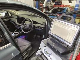
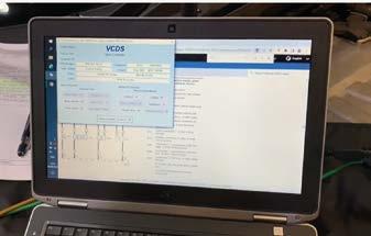
Retrieval of the stored DTCs were pulled in a complete car scan using ODIS and these were the faults stored in the convenience module:
• 1135 Interior Monitoring sensors – No signal/communication intermittent

By Gareth Davies AAE FIMI, Euro Performance
• 323 Vehicle inclination sensor – No signal/communication intermittent
• 1134 Alarm Horn – No signal/communication intermittent
• 323 Vehicle inclination sensor – Faulty intermittent
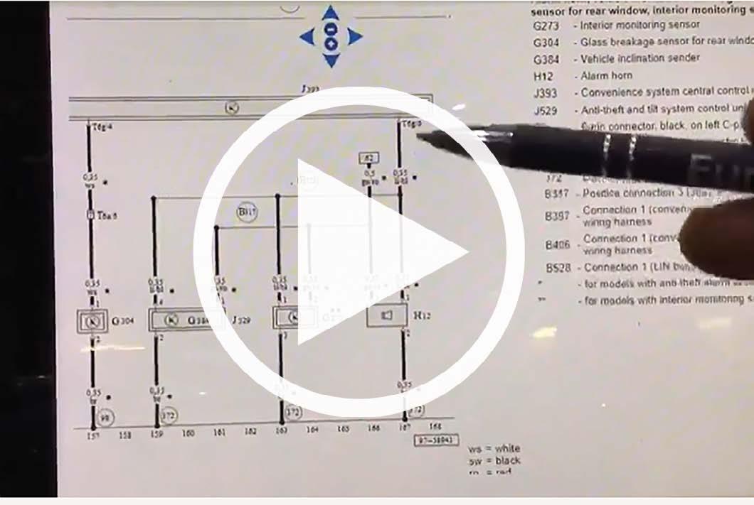
With this information and confirmation the symptom was replicable I was satisfied I had a good start point for my investigation work. Consulting technical data, I decided that checking any relationship between these components was important, and that a wiring diagram should furnish this answer. Looking at the wiring diagram I concluded that there are 3 separate sensors/units that each share the same root power, ground and a third wire. Studying the diagram, I could see they communicate with the convenience ECU via Lin Bus.




Lin Bus is a single 12v wire, low speed communication method, with a master and slave arrangement. Now at this stage I cannot be sure of a slave or master component failure, a wiring failure, or something more left-field of my peripheral.
I created a quick and simple plan to carry out some tests. My key questions and tests are:
Powers – Where does the supply come from?
Test methods – Fuse condition, volt drop testing, measured supply at components
Grounds – Where does the circuit ground?
Test Methods – Volt drop testing, measured ground at components
Lin Bus – Interpret Lin signal at connected components, what happens connected and disconnected
Basic principles were the foundations of my test plan and in keeping with the theme of ‘Time is money’ I needed to select the easiest and most logical test point(s) to start joining dots on a page that currently has lots of reference points, but no clear picture.
Test 1 – Power supply
I located the fused supply for all three components. Fuse confirmed by test light, removed to ensure integrity (legs/ corrosion) and this is good.
Test 2 – Easiest, least intrusive component of the group to inspect and check
Three tests to be carried out at this test point. Power supply, ground, and Lin activity. The test point was the interior monitoring sensors, which when referring to the current flow diagram does mention depending on spec this may or may not be fitted – on our car it was. I was able to identify the power supply, which confirmed as correct with no volt drop. I could confirm a good ground, cross checked with a test light validating another 12v supply, and cross checked for volt drop to ground. All good.
Test 3 – LIN Bus evaluation
At this point it was clear a LIN signal was present at the interior monitoring sensors but was not as expected. It was apparent from my limited knowledge of LIN Bus that the signal was corrupt. Familiar in what I should see, and a quick confirmation check with the very useful Diagnostic Assistance program, shows examples of good LIN, and LIN operation. I compared the signal with both the connected and disconnected and observed no change. This is the key test which should have showed some observed change if the network was performing correctly.
The other test that can be running in the background whilst your testing is being carried out is live data analysis. I felt it pertinent given the nature of the non-communicational faults stored to evaluate the live data change of the LIN slaves during my testing. For example, if when disturbing wiring during a wiggle test, or isolating a component suspected of being a contributor to the network transmission issue now detected, I would in theory be able to see a partial restoration of the communication status of these slaves when doing so. Really useful if you have a scan tool that is either Bluetooth connection to the multiplexer interface or has a really long lead (ODIS does) then you can have this in front of you when performing the tests. It may serve no useful purpose with some faults but could yield another clue with no extra effort being exerted.
Make it easy on yourself
At this point I had a useful amount of information from my testing. I had to make a new plan now to look at other points on the system to test. The logic I used here is to test at the next easiest point to gain the most information. I chose the alarm siren. This did require some intrusion, but the interior monitoring sensors were two tabs and two screws in the headlining, which was a piece of cake, the siren is OSF wheel off and arch liner down, whereas the inclination sensor was hidden somewhere up behind the driver’s side dash supposedly. “Pick your battles” is always my approach! You might have questioned my logic at this point and wondered why I hadn't gone straight to the inclination sensor, given one of the fault codes says, ‘inclination sensor – faulty’. I have learned over my time with the brand not to believe these faults and rate them as highly as I once did. My case study regarding an RS6 fuel pump control unit highlights why.
Something to remember when troubleshooting faults is a plausibility check of what it is you’re dealing with. Knowing your expected results is key. Can a component that is designed to work on a solid 12v supply function properly if it’s getting 6.8 volts? No, it can’t. Can that green crustiness at a plug connection really be the fault? Of course it could. In exactly the same way, is it the supply that is the fault or a flaky ground that increases resistance with the direction of the wind? All this questioning should remain at the forefront of any technician’s mind when approaching a fault. The basic principles are very often not far away from a route cause of failure. Hence the seemingly casual approach to the control unit faulty DTC being amongst others rather than a standout individual DTC entry.
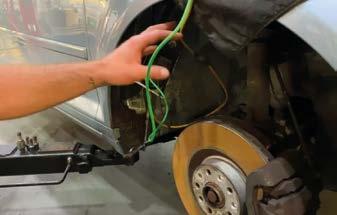
Fast forward to an exposed alarm horn siren (it’s an antitheft component so remember there may be shear bolts to deal with, which in this case there was) I was able to repeat the same set of tests that I had carried out earlier at the interior monitoring sensors. Sure, enough power and grounds checked out, and with the component connected I still had my bad LIN trace.
Something’s changed…
However, when disconnecting the component, I observed the Lin behaved differently to before. Instead of showing a virtual flatline 7v occasionally dropping to ground in a nonreferenceable waveform pattern, I now had a waveform operating between 12v and 7v and displaying telegrams. Furthermore, checking my live data PIDs I could now see an observed change to other slaves on the network. They were reporting a status change which said they were now communicating. A further stress test performed here shows that with the ‘bad apple’ out of the barrel can the system work otherwise? The answer was yes, when the vehicle assumed a simulated locked state, the interior monitor sensors reported a working state as did the inclination sensor.
With the diagnostic testing complete I moved to summarise my findings with the customer and quote for the repairs required; a new alarm siren unit and anti-theft bolt with the necessary labour. Notably, the labour content transparently less than the cost of diagnosis. This should be something considered in your fault assessment fee and approach, because if you are not charging suitably for diagnosis, you are likely to be left wanting in certain repair cases due to the effort to apply the fix is significantly less than the effort and skill to accurately troubleshoot the complaint effectively in the first instance.
The repair was carried out and the system operation was checked in a pre-assembled state, checking live data and operation when locked for a longer period in the workshop. There were no further instances of the alarm going off but the vehicle remained with us overnight to be absolutely sure before customer collection. The vehicle has since returned for MOT and was confirmed as fixed by the customer.
A fairly simple fault and case study in this guise, but was it made simpler by a logical approach and execution of testing? I think so, and I think a lot of the time reflecting on jobs before during and after the diagnosis chapter, what is the easiest route. Some jobs we come across for sure are really tricky longwinded affairs, but I think sometimes just a little thought and order to our approach results in the most effective use of time and skill, which we cannot forget are the only ‘things’ we as techs sell.



oils Page 39


