5 minute read
Rotating electrics: Low voltage hybrids


Moving knowledge forward on low -voltage hybrids
While there is nothing to fear from low-voltage technology, be wary of complacency. Rob Marshall, therefore, discusses the pertinent issues with remanufacturing exponent, Autoelectro, to establish the reasons why
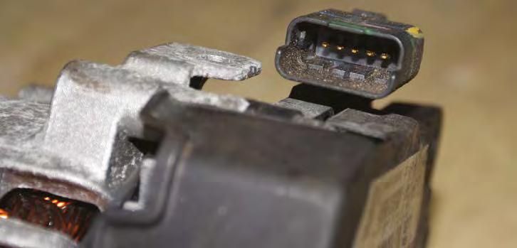
Be familiar with the low voltage micro/mild-hybrid application (i.e., under 48 volts), with which you are faced. Pictured is an early Bosch Stop-Start application for non-manual gearbox vehicles.
To reduce CO2 emissions (and, therefore, take advantage of taxation benefits) start-stop technology stalls the engine and restarts it promptly. These micro-hybrids were refined into mild-hybrids, the majority of which utilise 48-volt combined belt-driven starter-alternators.
Autoelectro reports that, because these costly units are tricky to copy accurately, remanufacturing is essential to introduce quality aftermarket replacements quickly. The company argues that quality remanufacturing is a preferable option over a copy part that has not been produced by the original manufacturer. Therefore, a removed faulty unit is still valuable as core.
A further issue is that some rotating electric components are becoming bespoke to certain models, so copy parts may not be viable, due to too low a production run. Even so, being familiar with the application on which you are working, adopting a logical diagnostics process, and addressing the fault, not just the symptom, will stand you in good stead.
Smart alternators
1. Some micro-hybrids can possess smart alternators, which charge at variable voltages. Between 10 and 18 volts are typical. Should the unit be found not to be charging at an expected constant voltage, or even not at all, something else on the vehicle may be responsible, instead of a faulty alternator. (Image courtesy of Bosch). 2. Communication between the alternator and engine ECU is via Pulse Width Modulated (PWM) data signals. Pictured are both LIN (Local Interconnect Network) and BSS (Bit Synchronous Interface) connections, which you are most likely to encounter. Alternatively, the Digital Field Monitor (DFM) connection sends an alternator load signal to the ECU. 'FR' directs a variable output of between zero and 11 volts to the ECU to assess the battery charge rate. Never introduce test voltages into these data wires.

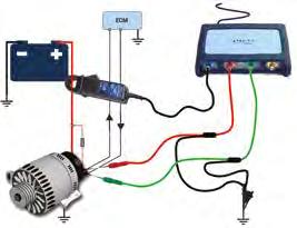
3. An oscilloscope displays real-time smart alternator responses to loading the electrical system. Yet, Autoelectro advises that you can disconnect the alternator-to-ECU communication wires (See Step A2), which enables the alternator to run independently of the ECU. The resultant voltages should measure between 14.5 and 14.8. Consider, however, that you may create the StopStart system to log a fault code, which you must reset afterwards. (Image courtesy of Pico Technology.)
Combined starter/alternators

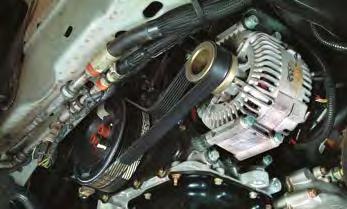
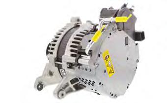
1. Low-voltage mild-hybrids can employ these units, mounted to the FEAD drive. A separate starter motor may be fitted for cold-start purposes. Valeo's StARS was the first massproduction combined starter-alternator unit, although OEMs use their own terminology. Ford uses the acronym, 'B-ISG', (Belt-driven Integrated Starter Generator), for instance. "Because these costly units are tricky to copy accurately, remanufacturing is essential to introduce quality aftermarket replacements quickly" ROTATING ELECTRICS
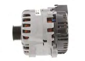
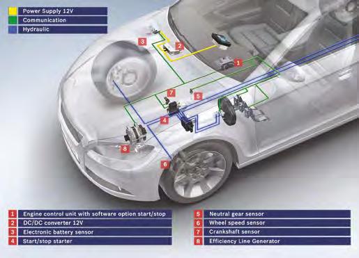
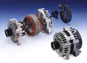
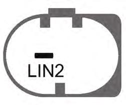
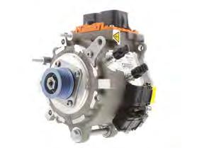
2. Valeo's later i-StARS integrated the previously separate power unit inside the alternator's main casing. For identification purposes, the rear-mounted black plastic cover houses these electronic components. The communications plug is also shown, where B+ is the positive battery supply, D refers to unused terminals, LIN provides the ECU communication protocol connection and GND is the ground/earth connection. 3. Be familiar with the whole system. This 2011 Peugeot 308 1.6-litre e-HDI has an 'e-booster' that supports the 12V battery (item 2), by supplying extra power, when starting the high-compression diesel engine (5). This comprises an ECU (1a) and a capacitor (1b) that provide extra current to the i-StARS combined starter/alternator unit (4). The whole system is controlled by a further ECU (3) via the communication network (blue line).

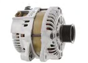
4. Not all carmakers employ the same systems. Mazda's I-ELOOP combined starter/alternator appeared in 2012, the FEAD-mounted alternator of which can generate up to 25v during deceleration. Yet, the conventional 12-volt battery cannot store this electrical energy without damage. Therefore, the system employs a separate capacitor that receives and discharges the power back into the system, when required. 5. Some 48-volts combined starter-alternators recuperate brake energy. Yet, as this is not performed via the road wheels (unlike conventional high voltage EVs), the regenerative energy comes through the Front End Auxiliary belt Drive (FEAD), therefore, increasing the engine braking effect. Some of these units become so hot, they require liquid cooling, such as this MercedesBenz item.
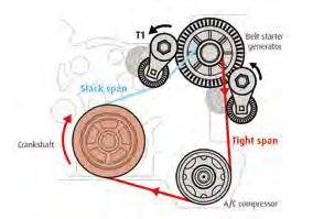
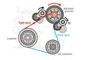
6. Some high-voltage hybrid models may also possess combined starter-alternators, such as vehicles that feature electric rear axle propulsion and combustion engine drive on the front. This Hybrid4 Peugeot component is rated at 415-volts, so it could be a potentially fatal mistake for the repairer to presume that it operates on a maximum of 48-volts. 7. Combined starter-alternators employ neither pulley-based clutches, nor decouplers. Some systems possess a simple single-stage tensioner; others have a more elaborate tensioning system that prevents belt slippage and absorbs engine torsional vibration. Pay special attention to the maintenance requirements and belt specifications when you service the FEAD drive. (Images courtesy of Valeo.)
tip:
Usable core is essential for successful remanufacturing. Autoelectro reports that robust connections of past alternators have been replaced with relatively fragile data connections to reduce weight and cost. However, they are far easier to break off accidentally, so be extra vigilant.