9 minute read
REFERENCE LIST


Prototype 2, was also is cut on the 1.5mm Plywood surface and joined the edges of MDF frames with zip ties.
As the inner raw of patterns failed in Prototype 2, we decided to extract the 3 raws of patterns from the center and test it. After we joined the surface to the frame, we observed that there occur no cracks.
Advertisement
So, the final model decided to be produced with this surface of the prototype, as the pattern drawing shown in Figure 49.
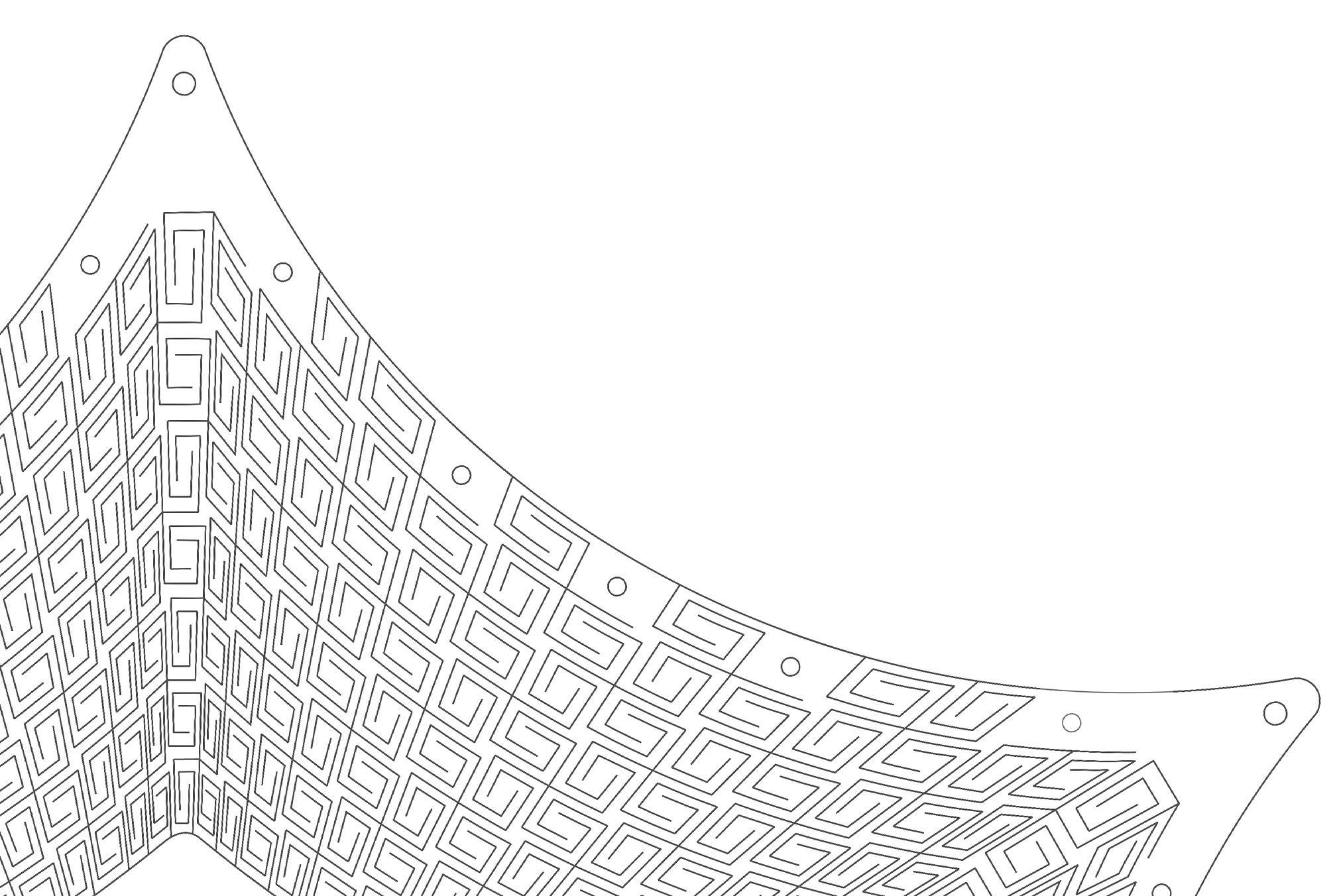
Figure 49: FINAL PATTERN
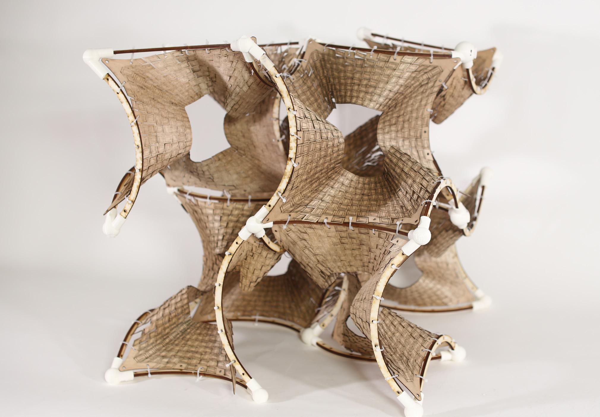
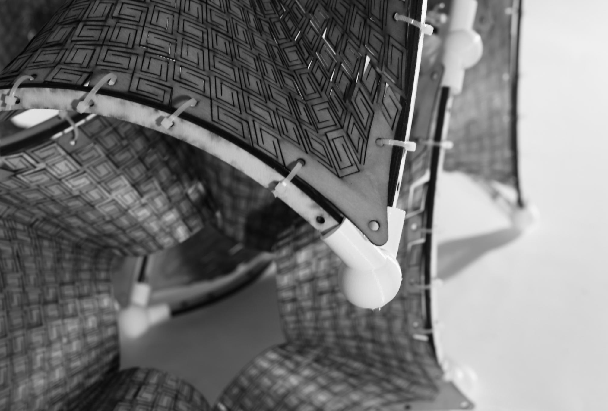
Figure 52: ARCH FRAMES ASEMBLY
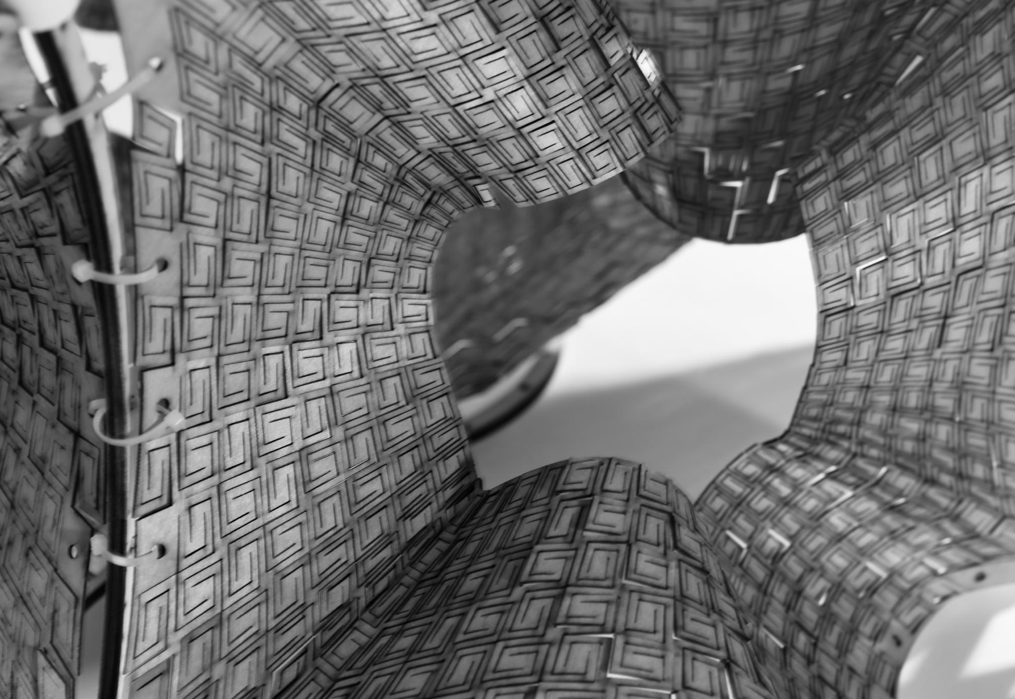
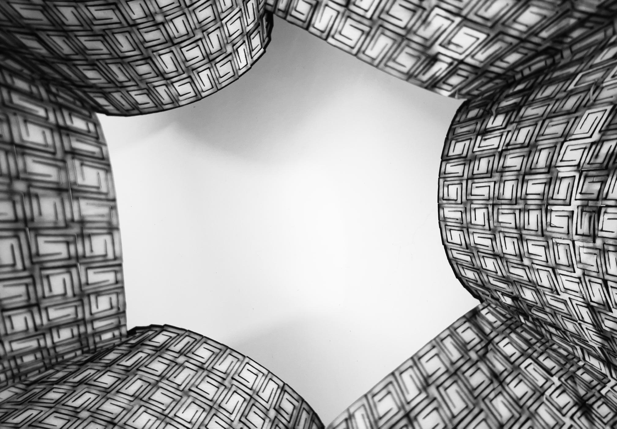
Figure 53: MATERIAL REDUCTION LIMIT
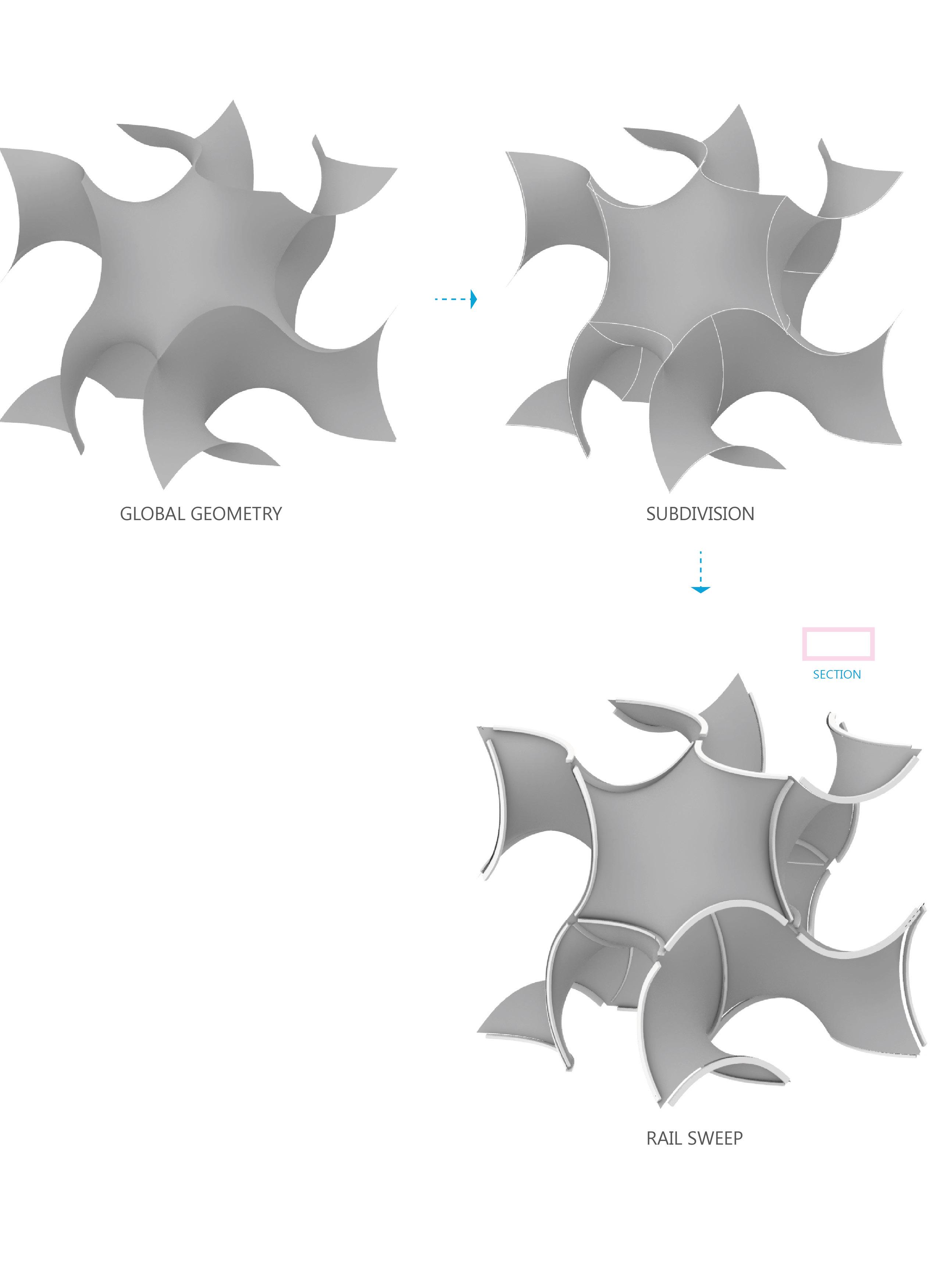
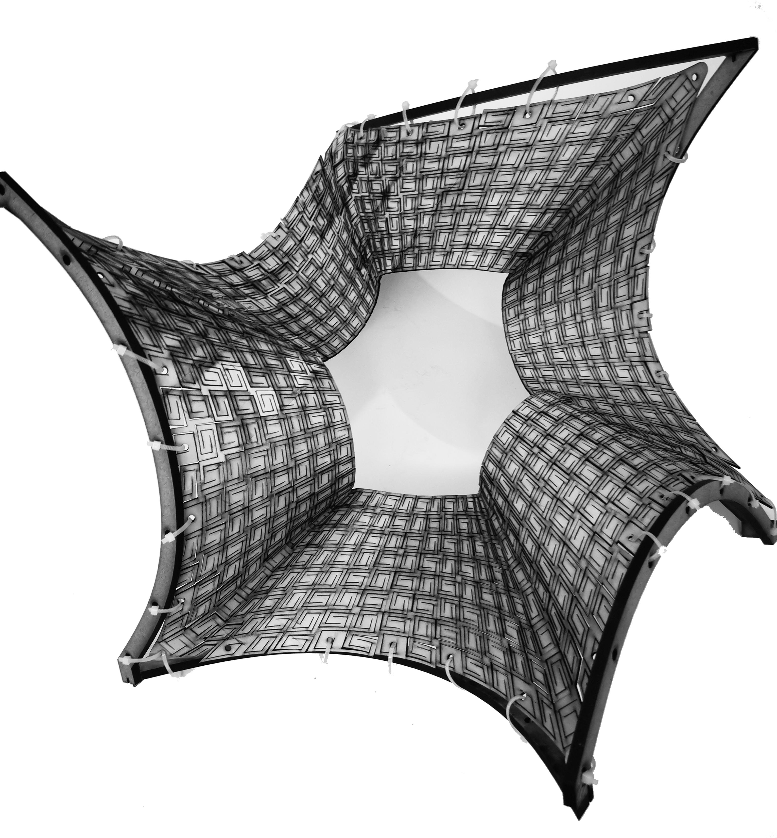
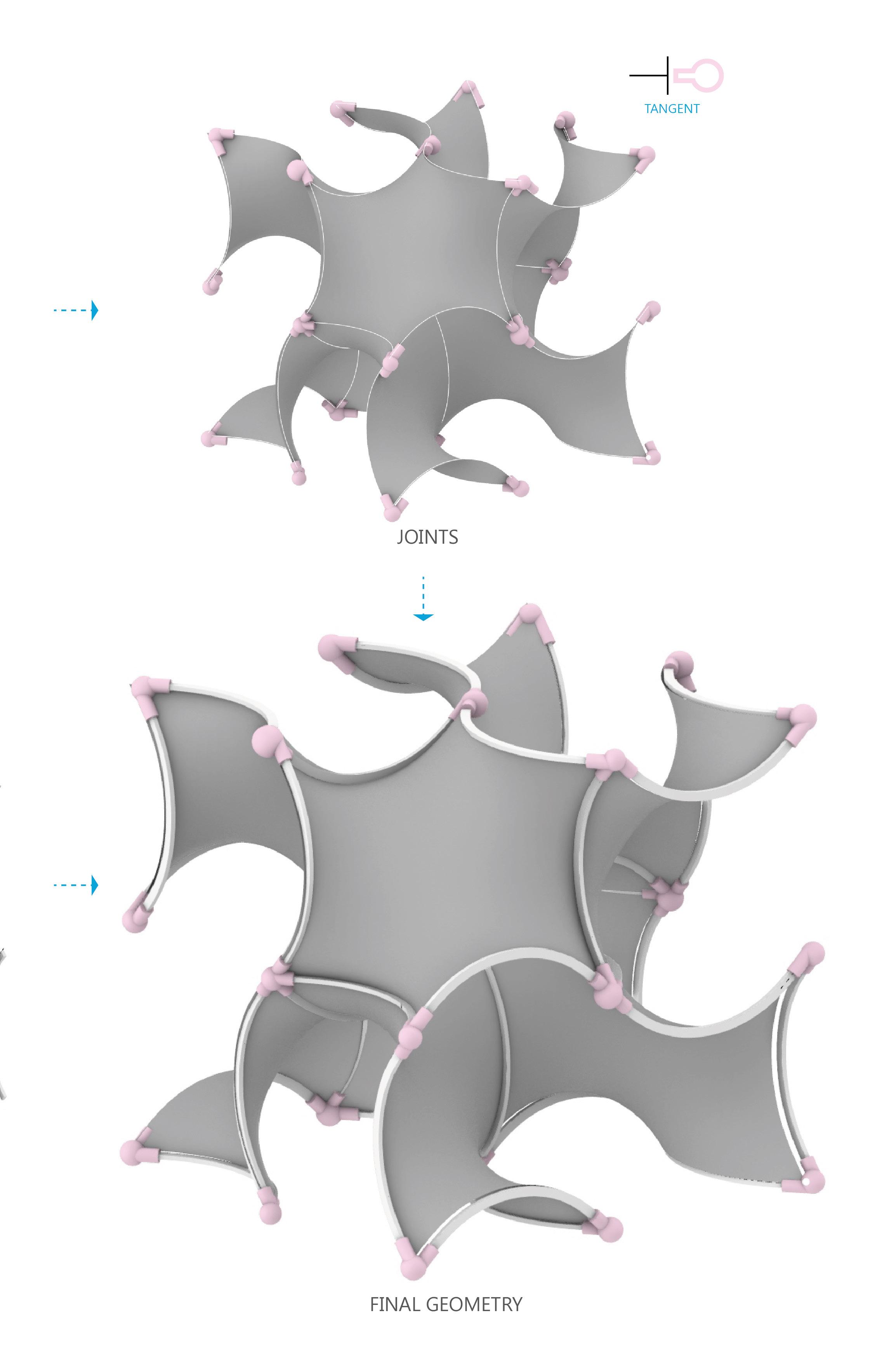
The flexible kerfed plywood needs to be assembled into a global geometry, thereby shaping the local geometry by means of a mold. The global geometry is subdivided into smaller local geometries, where the division curves, serve as the supports for the kerfed plywood to achieve its doubly curved surface. The beams that are translated from the division curves are held in place by 3D printed joinery. The combination of subtractive and additive manufacturing, with zip ties holding the kerfed member in tension, results in the formation of a Gyroid.
FABRICATION 08 FINAL MODEL
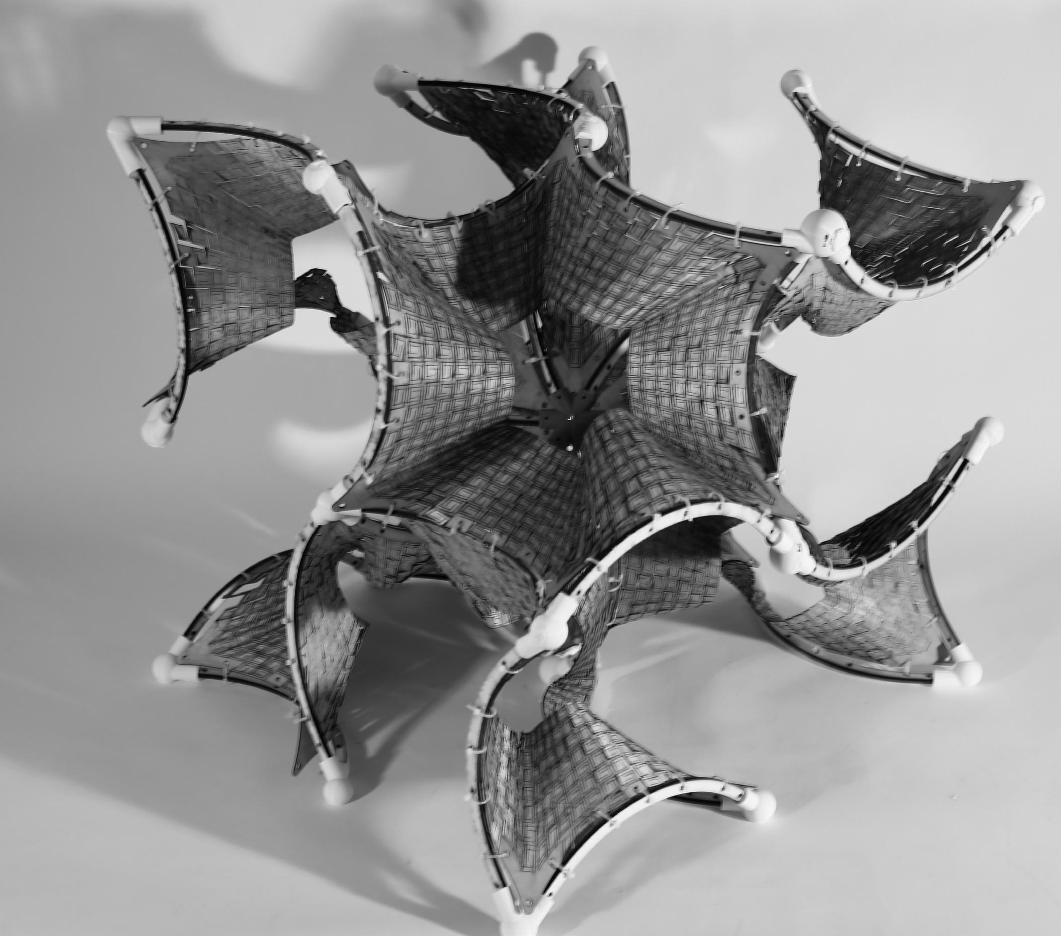
Figure 55: FINAL MODEL 8 SURFACES/ 1.5mm PLYWOOD
36 ARCH FRAMES/ 6mm PLYWOOD
252 ZIP TIES/ 7 EACH FRAME
24 CORNER JOINTS/ PLA
1 CENTER JOINT/ PLA
1 BOLT Figure 56: Digital model isometric
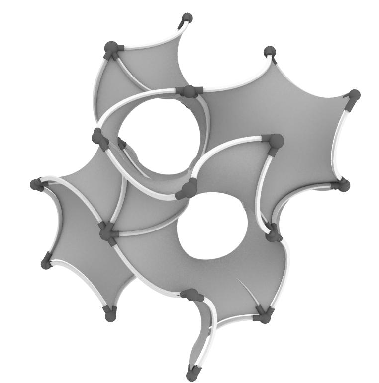
Figure 56: Digital model elevation

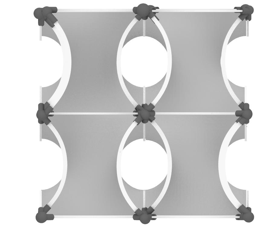
Figure 57: Digital model perspective
For the fabrication, 8 surfaces of 1.5mm plywood are joined with a central grey PLA joinery and 6mm plywood arch frames. On the corners, we used differently typed of joints with white PLA (that will be evaluated in the conclusion). In order to attach the surfaces into the frames, white plastic zip ties are used.
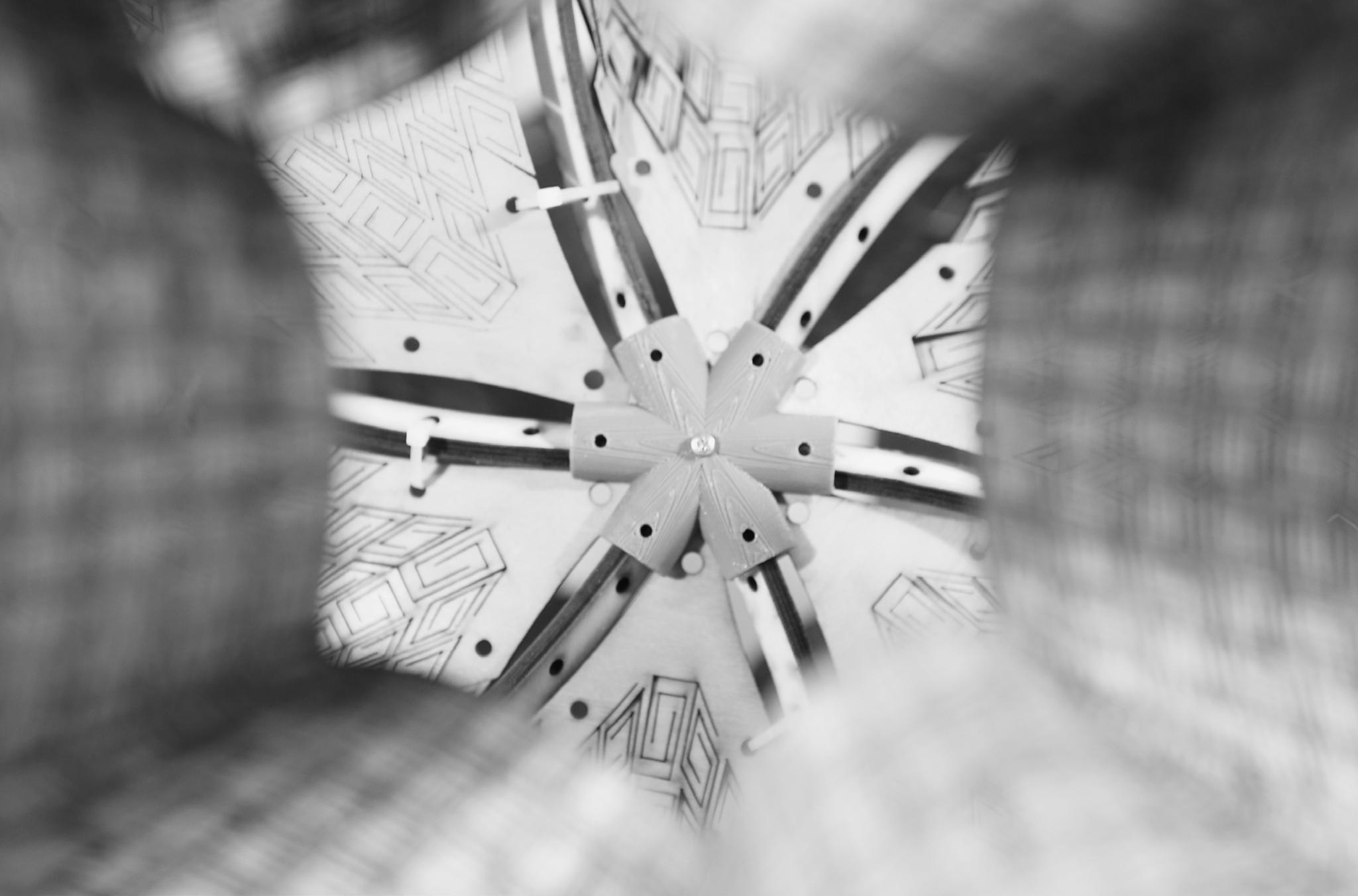
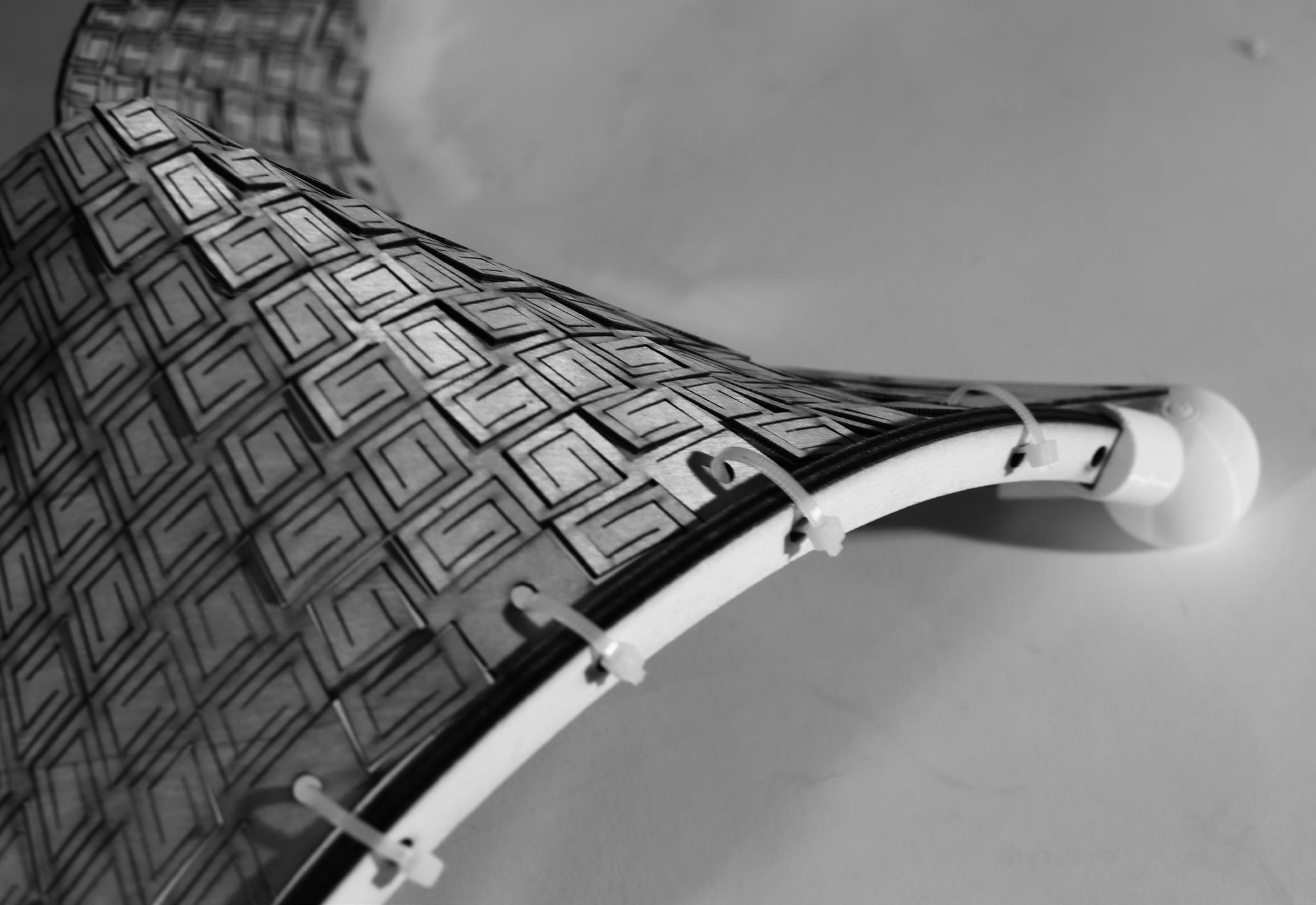
Center joint is designed to hold together the 6 central arch frames that are all joining in different angles. The joined is produced in 3d printer with gray PLA and stuck together with 2mm bolts.
Figure 61: CENTER JOINT Corner joints are designed to join 2, 3 or 4 arch frames depend on the location. They work in the same logic, as they are joining the frames with a centralized sphere. The joints are produced in 3d printer with white PLA and attached to the frames.
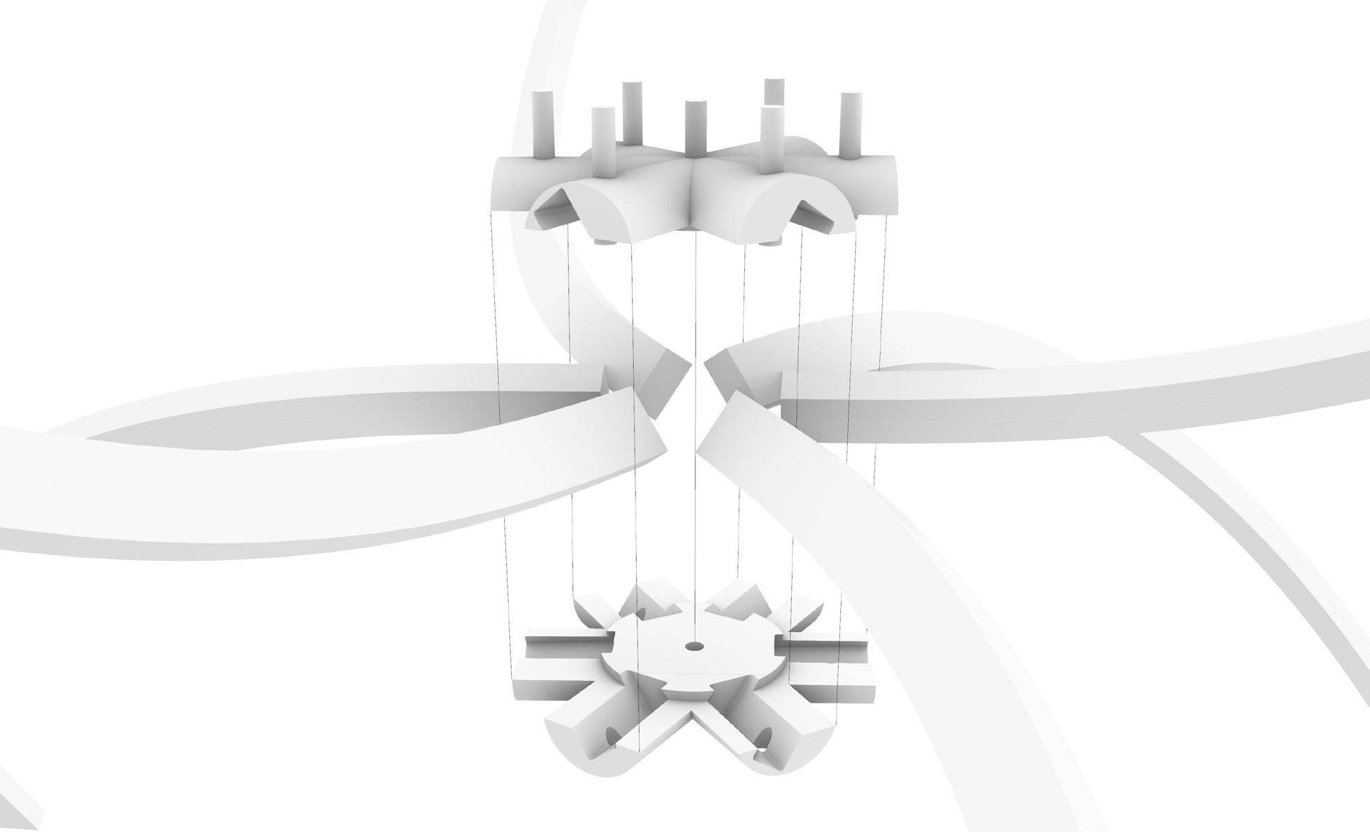
Figure 62: CORNER JOINTS
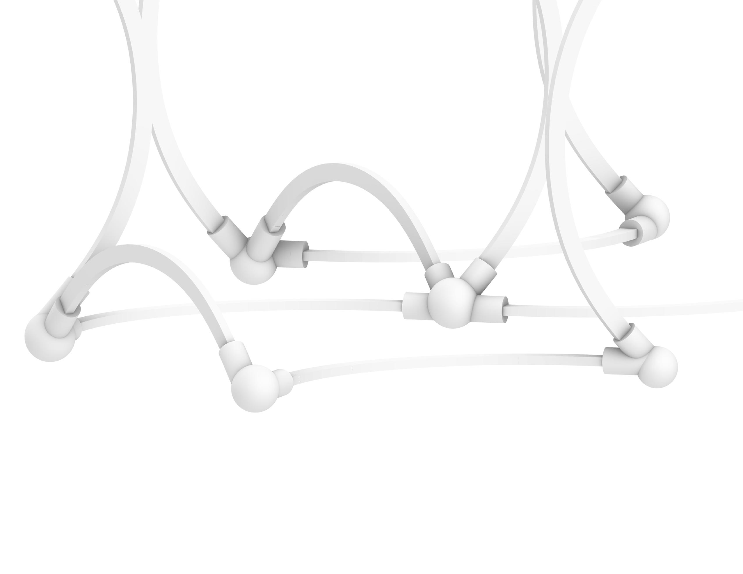

FIGURE 63: ISOMETRIC FIGURE 64: PERSPECTIVE
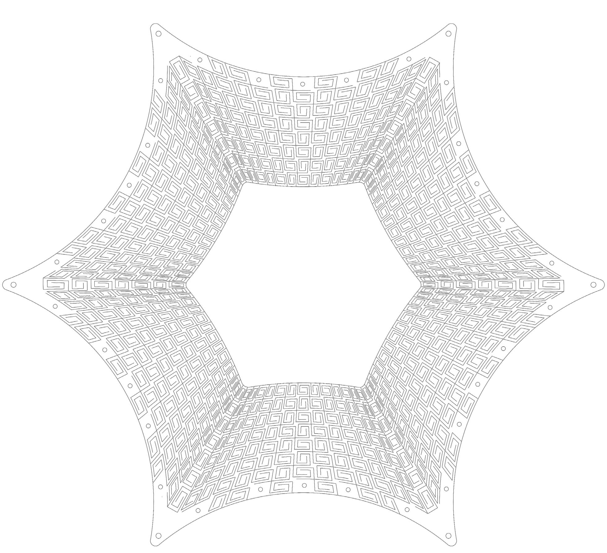
FIGURE 65: SURFACE GEOMETRY & PATTERN CORNER HOLE

MIDDLE HOLE
MOULD / 8 SURFACES
In the fabrication process, first, the plywood arch frames are joined together with PLA joints. 36 arch frames are joined with 24 corners and 1 central joint.
For the 8 plywood surfaces, they are all put in the water 48 hours before the as- sembly. Every 12 hours, the surfaces are checked if they were losing their stiffness or if they are still malleable and not getting rotten. So, after 48 hours, they are taken out of the water and dried out for 4 hours. After the drying process, the surfaces were ready to assemble.
Each surface attached to the frames one by one, with 2 people assistance, as the surfaces were still humid, they tended to broke easily. For a surface, first, the middle points are ties to the mold one by one for 6 edges of the surface. After the middle points, the corners are zipped to the frames followed by the remaining points. The zip ties are attached loosely at first stage, as soon as all the edges attached, the ties are tightened and the assembly completed.
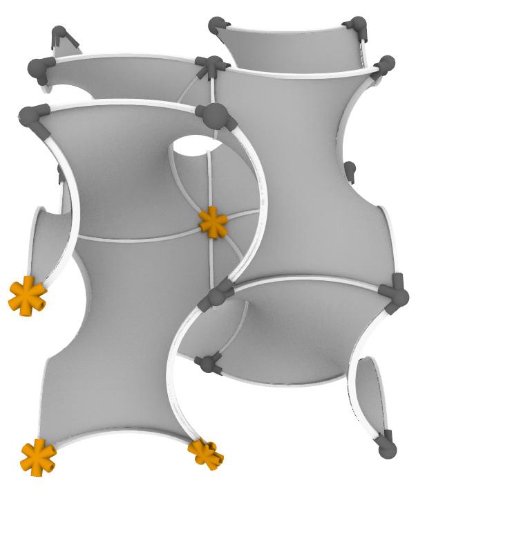
09A At first, the project started as exporting the gyroid geometry and the whole focus was to generate the doubly curved gyroid surface. As we progressed in the project, we focused to the idea of the gyroid geometry and only explored this option. We could have expanded our exploration range for geometry and implied what we learned from the gyroid and tried different options as well. The options could have been generated by scaling the gyroid geometry and joining them in different scales or to stretch the geometry as shown in Figure 66.
09B As we assembled the physical model, we realized that the corner joints were not suitable for the overall geometry. Although they were functioning well in terms of joining the arch frames properly, we could have designed a better corner joint, as we did for the central joint. The central joint could have been copied to the corners as well, also for emphasizing that the further modules can be attached to our module.
Another advantage of the central joint was the slits in the middle. As the plywood surfaces are attached to the frames, the corners were inserting the slits, so that the assembly will fit properly. Figure 66: Alternative geometries generated from gyroid

Existing corner joint
Existing center joint
New corner joints Figure 67: Alternative corner joints

Bolt
09C As the surface geometry is designed in Figure 41 and the assembled state is shown in Figure 53, in the central parts there occurs some foldings and these are uncontrolled geometries. Even though we can call them “emergent geometries” in the center and keep them as they are, as a further development, they can also be controlled in terms of introducing some tension cables or fixing them with additional frames.
09D The Karamba Analysis is applied on the surface without the cutting patterns. So, as the surface in the analysis did not have the carved out patterns, it was not so accurate for the final model. Additionally, the arch frames could have been structurally tested as well. As a further analysis, the frame and the tensile analysis can be done as follows:
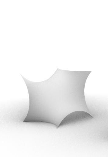
Frame The global geometry is subdivided by curves resulting in one subdivided surface that is repeated throughout. Creating Beam Elements from subdividing curves utilizing a rectangular cross-section, would then be taken forward for the location of its supports and material assignment. A series of points will be defined in the yz-plane corresponding to the module, as endpoints of the beam elements and will be supported by joints. Figure 69: Inner surface

Parts to be controlled
Tensile The local geometry as a result of our kerfing method applied appears to have negligible compressive and flexural strength. The behavior of the material is like the case of membrane structures, hence we removed regions of kinks in the center – to avoid wrinkles. To further recreate this behavior on or plywood we could try to reduce the shell thickness so that bending effects get neglectable and define the supports, to get negligible compression forces. If we set G=0.5E the material results with a lateral expansion factor of zero, this would correspond to our desired behavior.
09E As a further development for the pattern, we realized that in the square spiral pattern, there occur some shear forces through the majority (%77 overall) of the cuts within the subdivision as shown in Figure 70. So, we would take a pattern that prevents the shear propagating through the cut surface better compared to the square pattern. In a circular pattern (Figure 71), as the sheer will propagate to the center directly, this could be a better option. However, a circular pattern may have some potential problems in applying it to our geometry. Furthermore, hexagonal spiral pattern (Figure 72) can also have a potential to experiment and it may be easier to apply in our surface, as the surface also has 6 edges and the whole surface performs as 6 different surfaces.
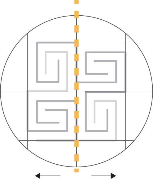
Figure 70: Square spiral grid Figure 71: Circular spiral grid

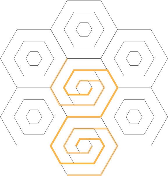
Figure 72: Hexagonal spiral grid
Cabrinha, Mark. “From Bézier to NURBS: Integrating Material and Digital Techniques through a Plywood Shell.” In ACADIA 2005 Conference: Smart Architecture, 156–69, 2005.
Cabrinha, Mark, Tuğrul Yazar, Mara Capone, Emanuela Lanzara, Rukmini Dey, Pradip Kumar, Rahul Kumar Singh, et al. No Title. Accessed November 16, 2019. https://www.researchgate.net/publication/335703347_Convolutas_Developable_strips_and_digital_fabricated_lightweight_architecture.
Capone, Mara, and Emanuela Lanzara. “Kerf Bending: Ruled Double Curved Surfaces Manufacturing,” 653–60. Editora Edgard Blucher, Ltda., 2018. https://doi.org/10.5151/sigradi2018-1389.
———. “Parametric Kerf Bending: Manufacturing Double Curvature Surfaces for Wooden Furniture Design.” In Lecture Notes in Civil Engineering, 24:415–39. Springer, 2019. https://doi.org/10.1007/978- 3-030-03676-8_15.
Dey, Rukmini, Pradip Kumar, and Rahul Kumar Singh. “Local Interpolation for Minimal Surfaces,” July 24, 2019. http://arxiv.org/abs/1907.10780.
Enlow, J. D., R. L. Enlow, K. M. McGrath, and M. W. Tate. “Modeling Liquid Crystal Bilayer Structures with Minimal Surfaces.” Journal of Chemical Physics 120, no. 4 (January 22, 2004): 1981–89. https:// doi.org/10.1063/1.1635811.
francisco.gonzalez. “(PDF) Convolutas Developable Strips and Digital Fabricated Lightweight Architecture,” 2019. https://www.researchgate.net/publication/335703347_Convolutas_Developable_ strips_and_digital_fabricated_lightweight_architecture. Garstecki, P., and R. Holyst. “Scattering Patterns of Self-Assembled Gyroid Cubic Phases in Amphiphilic Systems.” Journal of Chemical Physics 115, no. 2 (July 8, 2001): 1095–99. https:// doi.org/10.1063/1.1379326.
Longuet Higgins, M. S. “The Statistical Distribution of the Curvature of a Random Gaussian Surface.” Mathematical Proceedings of the Cambridge Philosophical Society 54, no. 4 (1958): 439–53. https://doi.org/10.1017/S0305004100002991.
Petrelli, Daniela, Luigina Ciolfi, Dick van Dijk, Eva Hornecker, Elena Not, and Albrecht Schmidt. “Integrating Material and Digital.” Interactions 20, no. 4 (2013): 58. https://doi. org/10.1145/2486227.2486239.
Ramaswamy Pillai, Swaroop, Sahith Reddy Madara, and Chithirai Pon Selvan. “Predication of Kerf Width and Surface Roughness in Waterjet Cutting Using Neural Networks.” Journal of Physics: Conference Series 1276 (August 2019): 012011. https://doi.org/10.1088/1742- 6596/1276/1/012011.
Stavrić, M., M. Manahl, and A. Wiltsche. “Discretization of Double Curved Surface.” In Challenging Glass 4 and COST Action TU0905 Final Conference - Proceedings of the Challenging Glass 4 and Cost Action TU0905 Final Conference, 133–40, 2014. https://doi.org/10.1201/ b16499-23.
Velimirovic, Ljubica, Grozdana Radivojevic, Mica Stankovic, and Dragan Kostic. “Minimal Surfaces for Architectural Constructions.” Facta Universitatis - Series: Architecture and Civil Engineering 6, no. 1 (2008): 89–96. https://doi.org/10.2298/fuace0801089v.
Yazar, Tuğrul. “The Relationship Between Gaussian Curvature and Surface Panelization Approaches in Architecture.” MEGARON / Yıldız Technical University, Faculty of Architecture E-Journal, 2018. https://doi.org/10.5505/megaron.2018.50103.


