
COLUMN HARDWARE
www.idex-hs.com 12 114 150 FLUIDICS INTRODUCTION 156 11 FLUIDICS FLUIDIC CONNECTIONS VALVES DEGASSERS COLUMN HARDWARE OPTICS DEGASSERS
VALVES
www.biotechfluidics.com
FLUIDIC CONNECTIONS

Valves
Our valves are an integral part of advanced fluid-handling solutions for a wide range of analytical instrumentation and clinical diagnostic systems. Our valve options include manual valves for lower frequency use and rotary shear valves that meet the high duty cycle requirements of UHPLC and also come in high and low pressure versions to meet your system requirements. We also offer check valves when there is a need to limit the fluid flow to one direction. Our Back Pressure Regulators products are designed to enhance system performance through outgassing prevention. All of our valve products, components, tools, and accessories are designed keeping our customer’s system needs first.
www.idex-hs.com 143 121 124 126 115 115 134 119
FLUIDICS VALVES 114 BACK PRESSURE REGULATORS MANUAL VALVES SPARE PARTS VALVE ACCESSORIES ROTARY SHEAR VALVES VALVE OVERVIEW & FUNCTIONS FLOW REGULATING VALVES STAND ALONE VALVE PRODUCTS www.biotechfluidics.com
FLUIDICS
VALVE OVERVIEW & FUNCTIONS
Valve Module
ACTUATED VALVES
UP TO 15,000 PSI
Switching
2-Position, 6-Port 2-Position, 10-Port
Injection For Injection, add the appropriately sized Sample Loop to the Switching valves above
Selection 6-Position, 7-Port UP TO 6,000 PSI
Switching
2-Position, 6-Port (Analytical and Nano Scale) 2-Position, 10-Port (Analytical and Nano Scale)
Injection For Injection, add the appropriately sized Sample Loop to the Switching valves above 2-Position, 6-Port (vertical port)
Selection 6-Position, 7-Port UP TO 125 PSI
Switching
2-Position, 6-Port 2-Position, 6-Port (Double 3-Way)
Selection 6-Position, 7-Port 10-Position, 11-Port
Valve Module Flow Configurations
MANUAL VALVES
UP TO 9,000 PSI
Injection 2-Position, 6-Port (Front-Loading, 9,000 psi) UP TO 6,000 PSI
Switching 2-Position, 6-Port (Analytical and Micro Scale)
Injection 2-Position, 6-Port
Selection 6-Position, 7-Port UP TO 1,000 PSI
Switching
2-Way, Right Angle 4-Position, 4-Port
3-Way, T-Shape 4-Position, 4-Port 4-Way, Diagonal Flow 4-Position, 4 Port
Injection 2-Position, 6-Port
Selection 6-Position, 7-Port
Rotary Shear Valves
Our Rotary Shear Valves were developed in tandem with the evolution of liquid chromatography, where combinations of elevated system pressures, aggressive chemicals, and ever-diminishing fluid volumes continually challenged system manufacturers who required highly precise fluid control and delivery. Today, many other disciplines utilize Rotary Shear Valves for their versatility, reliability, repeatability, long system uptime, and easy preventive maintenance.

www.idex-hs.com
Stator
Rotor
Flow
Page
Configurations
119
119
119
Page
123
123
123
FLUIDICS VALVES VALVE OVERVIEW & FUNCTIONS 115 FLUIDICS FLUIDIC CONNECTIONS VALVES DEGASSERS COLUMN HARDWARE OPTICS www.biotechfluidics.com
Valve Overview and Functions (Cont.)
Choosing a Rotary Shear Valve
Evaluating some simple variables will assist you in choosing the best valve for your needs.
Identify the Operating Pressure of Your Instrument or Application
Valves are designed to repeatedly deliver specific fluids to different locations in a fluidic circuit. Achieving fluidic precision at 15,000 psi requires different valve-design features than those required to achieve fluidic precision at 100 psi. A wide variety of variables such as valve architectures, metals, polymers, coatings, actuation speeds, and manufacturing techniques have been tested to achieve the fluidic accuracy and precision required for the full array of pressure conditions in life science applications. In this catalog, we define four separate pressure groupings:
Up to 15,000 psi (1,035 bar) UHPLC/Fast Chromatography
Up to 6,000 psi (410 bar) HPLC
Up to 1,000 psi (69 bar) Medium Pressure Applications
Up to 125 psi (8.5 bar)
Low Pressure/ Atmospheric Pressure
Identify the Range of Flow Rates in Your System
Because Rotary Shear Valves have been used most often in chromatography systems, certain flow rate ranges have evolved functionally. However, these ranges can apply to any system, not just chromatography:
Micro/Nano Scale — flow rates less than 100 µL per minute
Analytical Scale — flow rates from 100 µL to 10 mL per minute
Prep (or Semi-Prep) Scale — flow rates greater than 10 mL per minute
Decide What You Want the Valve to Do
In this chapter Rotary Shear Valves perform three functions:
Switching one or more flow paths to a different destination under pressure
Injection into a flowing stream under pressure
Selection/distribution of a variety of system liquids by means of a common port
Read more about valve functions on page 114.
Identify Whether You Want Automated or Manual Control
An automated valve offers more sophisticated functionality. Choose an automated valve if the application requires fast, consistent flow-stream switching. Some other advantages of automated valves include control options (PC- or instrument-triggered), higher torque operation, valve-position feedback, or very small flow paths.
Choose a manual valve if your application involves low frequency of use, demands operator control, or involves injection of smaller sample volumes. (See page 122 for more on Single Mode vs. Dual Mode operation.)
Identify
the Chemical
Compatibility Requirements Related to Your Fluids
Consulting the chemical compatibility chart in the Technical Resources section at the back of The IDEX Health & Science Laboratory Products catalog helps identify what valve materials to use — and avoid — in your application. You can also find Chemical Compatibility information at www.idex-hs.com under Materials and Tools.
Identify
Fluidic
Connection Requirements in Your System
The rotary shear valves in this catalog accommodate one or more of the following tubing outer diameters: 1/8”, 1/16”, or 1/32”.
Effects of Valves & Tubing on Resolution
The effect of tubing on analytical and microscale analyses can be significant. Since dispersion caused by tubing is proportional to the fourth power of diameter, large bore tubing should be avoided when performing analytical scale or microscale analyses. Tubing ID size ≤ 0.25 mm (0.010”) is recommended.
Consider a system with injection and column switching valves and analytical columns with small-bore connecting tubing. The chromatograms below, made using a typical analytical chromatograph, show these effects. Scheme A is the control (injection valve column detector) with no valve in the system. In Schemes B and C, two model 7060 Six-Position Switching Valves were placed side by side (injection valve valve #1 column valve #2 detector).
The injection valve and detector were connected to these valves by the same tubing used in the control. The extra tubing pieces required to connect the valves to the column were a 10 cm length for valve #1-to-column, and a 35 cm length for column-to-valve #2. The diameters of these tubes are indicated in the experimental details, to the right.
Comparison of Observed
Column Plates of Analytical and MicroScale Injection Valves
k’ = 0.6
k’ = 1.5
k’ = 7.9
77258125
2930505472%
4653690448%
787583055.0%
UV detector: 1 µL volume, 4 mm path. Sample volume: 2 µL, partial-filling method.
Column: 2 mm ID x 100 mm long, 4 µm C-18. True plates of column = 11,570.
Effects of Valves and Tubing on Resolution
(A) Column Only (C) Valve w/ 0.020” Tubing (B) Valve w/
Conclusion: These sequential chromatograms show the effect of adding volume to the flow path through the addition of components.
(A) Establishes a baseline quality of separation with the minimum volume of liquid in the flow path.
(B) Adding a valve plus smaller-ID tubing, and thereby increasing the liquid volume only marginally, barely affects the separation. However in
(C) Adding a valve plus larger-ID tubing, thereby increasing the liquid volume in the flow path to a greater degree, distinctly impairs the quality of the separation and the detectable sample.
www.idex-hs.com
FLUIDICS VALVES VALVE OVERVIEW & FUNCTIONS
0.007” Tubing
116 FLUIDICS FLUIDIC CONNECTIONS VALVES DEGASSERS COLUMN HARDWARE OPTICS www.biotechfluidics.com
WHAT IS MAKE-BEFOREBREAK ™ , AND WHEN DOES IT MATTER?
Make-Before-Break is a unique design feature of certain dual-mode manual injection valves.
Flow paths of model 7725(i) and 9725(i) with MBB design
Switching Valves
Switching valves dynamically alternate between two fluid paths without manually disconnecting plumbing. In Chromatography, these valves can be used for column switching, backflushing, sample enrichment, and other techniques. In Diagnostic or Sequencing applications, the switching valve may alternate flow paths to enable back flushing or other fluidic tasks within the instrument.
To maintain a constant, desired highpressure flow, our Make-Before-Break (MBB®) design creates continuous flow between the LOAD and INJECT positions that virtually eliminates pressure transient shock to the system. A passage in the stator face makes a new connection before old connections break. The MBB design — an improvement over bypass-style injectors — does not dilute the sample and is easy to maintain and troubleshoot.
Our switching valves operate between two positions, and may have 6 or 10 ports on the face of the stator (2/6 or 2/10). The flow paths connect ports around the circumference of the stator. The manual switching valves (to 1,000 psi) described on page 123 have different flow path geometry as noted.
Injection Valves
Our injection valves are a form of switching valve. Injection valves can be automated or manual, and they are generally utilized in the two-position, six-port (2/6) configuration and have a sample loop attached.
The purpose of an Injection valve is to introduce a sample into a flowing stream of liquid. Some Switching valves become Injection valves by the addition of a Sample Loop (a defined length of tubing and fittings configured to match the angle of the valve ports). Sample is loaded and held in the loop until injection is triggered, either manually or automatically.
Injection valves are classified as either Single or Dual Mode based on how the Sample Loop can be filled. A Single Mode Injection valve requires complete filling of the sample loop and is configured for Rear loading, generally in an auto-sample configuration. A Dual Mode Injection valve allows either partial or complete filling of the loop, and introduces sample by syringe through the needle port built into the valve shaft. Complete filling of the sample loop in both the Dual and Single Mode Injection valves provides greater repeatability injection to injection. (See the Application Note, page 131 for greater detail on partial vs. complete loop filling.)
www.idex-hs.com
Rotor Seal Grooves MBB Passage Position C Rotor Seal Grooves MBB Passage Position B Position A Shaft End Rotor Seal Stator Face Stator Rotor Seal Groove Stator Face Seal Column Pump MBB Passage MBB valve Non-MBB valve Pressure shock Inject Pressure Time
1 1 6 6 5 5 4 4 3 3 2 2 Flow path of Two-Position, Six-Port Switching Valve Position 1 Position 2 Flow path of Two-Position, Ten-Port Switching Valve Position 1 Position 2 1 2 3 4 5 6 7 8 9 10 1 2 3 4 5 6 7 8 9 10 Flow path of Two-Position, Six-Port Injection Valve LOAD 6 5 4 3 2 1 Column Pump Waste Sample INJECT 6 5 4 3 2 1 Column Pump Waste Sample FLUIDICS VALVES VALVE OVERVIEW & FUNCTIONS 117 FLUIDICS FLUIDIC CONNECTIONS VALVES DEGASSERS COLUMN HARDWARE OPTICS www.biotechfluidics.com
Valve Overview and Functions (Cont.)
Selection Valves
Selection valves enable discrete connections among multiple system liquids (mobile phase, reagents, buffers) by means of a common port (inlet or outlet) connected to a number of different reciprocal ports. In Diagnostic or Sequencing applications, the selection valve alternates between different reagents or sample streams.
Numerous configurations exist among selection valves (e.g., 6-position 7-port, or 10-position 11-port), but these valves typically operate between more than two positions. The ports are usually spaced radially, or outward in some manner around the center port of the stator.
APPLICATION NOTE
Six column selection using two selection valves.
www.idex-hs.com FLUIDICS VALVES VALVE OVERVIEW & FUNCTIONS Pump Sample Injector 1 6 5 4 3 2 1 7 23 456 1 6 5 4 3 2 Detector
Flow path of Six-Position, Seven-Port Selector Valve 7 6 1 2 3 4 5
118 FLUIDICS FLUIDIC CONNECTIONS VALVES DEGASSERS COLUMN HARDWARE OPTICS www.biotechfluidics.com

Stand Alone Valve Products
An automated valve offers more sophisticated functionality. Choose an automated valve if the application requires fast, consistent flow-stream switching. Some other advantages of automated valves include control options (PC- or instrument-triggered), higher torque operation, valve-position feedback, or very small flow paths.
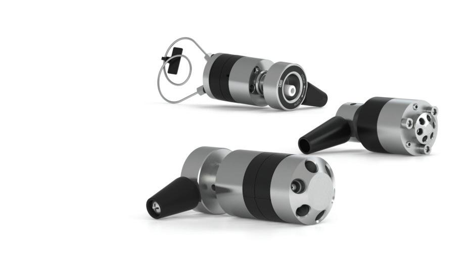
MX Series II
MXT to 15,000 psi (1,035 bar)
MXP to 6,000 psi (410 bar)
MXX to 125 psi (8.5 bar)
Add our MX Series II™ actuated valves to your existing instrument or use in stand-alone lab configurations. MX valves can be controlled remotely or operated manually using the push-button front panel with LED position indicator. MX valves connect to your instrument or PC through contact closure, BCD, serial port, or USB. Commands can be sent to the MX valves using your chromatography software or the included proprietary software for timed-events programmability.
Available flow rates include options for Analytical, Micro/Nano, or Semi-Prep in a range of pressure capabilities. Valve liquid ends are available in materials chosen to be chemically inert and biocompatible. Routine maintenance using authorized RheBuild® kits (page 124) or — for the higher-pressure MXP and MXP valves — the Rapid Replacement Pods™ (page 120) assures optimal performance.
ACTUATED
SWITCHING
UP TO 15,000 PSI (1,035 BAR)
MXT715-000 2-Position, 6-Port
MXT715-102 2-Position, 10-Port
10-32 Ports for 1/16” OD TubingUltraLifePD715-000
10-32 Ports for 1/16” OD TubingUltraLifePD715-102
INJECTION For Injection, add the appropriately sized Sample Loop to the Switching valves above SELECTION
MXT715-105 6-Position, 7-Port
10-32 Ports for 1/16” OD TubingUltraLifePD715-105 ea. All of these MXT valves include a set of 1/16” fittings. Replacement Fittings for MXT valves can be located on page 133. ACTUATED VALVES UP TO 6,000 PSI (410 BAR) SWITCHING
MXP7900-000 2-Position, 6-Port 10-32 Ports for 1/16” OD TubingDuraLife®* PD7900 ea.
MXP7960-000 2-Position, 10-Port 10-32 Ports for 1/16” OD TubingDuraLifePD7960 ea.
MXP7980-000 Obsolete 2-Position, 6-Port, Nano, 5,000 psi (345 bar) M4 Ports for 1/32” OD TubingDuraLife IIPD7980
MXP7986-000 Obsolete 2-Position, 10-Port, Nano, 5,000 psi (345 bar) M4 Ports for 1/32” OD TubingDuraLife IIPD7986
MXP9900-000 2-Position, 6-Port, Biocompatible, 5,000 psi (345 bar)10-32 Ports for 1/16” OD TubingPEEK PD9900
MXP9960-000 2-Position, 10-Port, Biocompatible, 5,000 psi (345 bar)10-32 Ports for 1/16” OD TubingPEEK PD9960
INJECTION For Injection, add the appropriately sized Sample Loop to the Switching valves above MXP7920-000 Obsolete 2-Position, 6-Port, Vertical Port 10-32 Ports for 1/16” OD TubingDuraLifePD7920 ea. SELECTION
MXP7970-000 Obsolete 6-Position, 7-Port 10-32 Ports for 1/16” OD TubingDuraLife II**PD7970
* DuraLife is a proprietary material combination of SST and an advanced polymer.
** DuraLife II is a proprietary material combination consisting of Titanium and an advanced polymer. All of these MXP valves include a set of 1/16” fittings. Replacement Fittings for MXP valves can be located on page 133. ACTUATED VALVES UP TO 125 PSI (8.5 BAR) SWITCHING
MXX777-601 Obsolete 2-Position, 6-Port Accepts Either 1/16” or 1/8” TubingRPC-7* 1/16” and 1/8” ea.
MXX777-603 Obsolete 2-Position, Double Three Way Accepts Either 1/16” or 1/8” TubingRPC-7 1/16” and 1/8” ea.
MXX777-612 Obsolete 2-Position, 6-Port, Large Bore Accepts Either 1/16” or 1/8” TubingRPC-7 1/16” and 1/8” ea. SELECTION
MXX777-605 6-Position, 7-Port Accepts Either 1/16” or 1/8” TubingRPC-7 1/16” and 1/8” ea.
MXX777-616 Obsolete 6-Position, 7-Port, Large Bore Accepts Either 1/16” or 1/8” TubingRPC-7 1/16” and 1/8” ea.
MXX778-605 10-Position, 11-Port Accepts Either 1/16” or 1/8” TubingRPC-7 1/16” and 1/8” ea. * RPC-7 Proprietary Polymer Combination. All of these MXX valves include a set of 1/16” and 1/8” ferrules. Replacement Fittings for MXX valves can be located on page 133.
www.idex-hs.com
FLUIDICS VALVES STAND ALONE VALVE PRODUCTS Part No. Description Ports, Connections Wetted MaterialRapid Replacement Pod Qty.
VALVES
ea.
ea.
ea.
ea.
ea.
ea.
ea.
119 FLUIDICS FLUIDIC CONNECTIONS VALVES DEGASSERS COLUMN HARDWARE OPTICS www.biotechfluidics.com

Rapid Replacement Pods™
For IDEX Health & Science MX Series II Valves
Zero downtime maintenance
Improves lab throughput
To help keep your instrument online and performing at maximum precision, select the exact Rapid Replacement Pod for your higher pressure MX Series II valves. Replacement pods are easily exchanged as part of scheduled preventive maintenance, or in an emergency, a pod can be substituted quickly while the original is examined and maintained at your convenience. The pod kit contains complete instructions for removal and replacement.


www.idex-hs.com
FLUIDICS VALVES ROTARY SHEAR VALVES RAPID REPLACEMENT PODS
Part No. Description For Valve Part No. Qty. TO 15,000 PSI (1,035 BAR) SWITCHING PD715-000 Rapid Replacement Pod MXT715-000 ea. PD715-102 Rapid Replacement Pod MXT715-102 ea. SELECTION PD715-105 Rapid Replacement Pod MXT715-105 ea. UP TO 6,000 PSI (410 BAR) SWITCHING PD7900 Rapid Replacement Pod MXP7900-000 ea. PD7960 Rapid Replacement Pod MXP7960-000 ea. PD7980 Obsolete Rapid Replacement Pod MXP7980-000 ea. PD7986 Obsolete Rapid Replacement Pod MXP7986-000 ea. PD9900 Rapid Replacement Pod MXP9900-000 ea. PD9960 Rapid Replacement Pod MXP9960-000 ea. INJECTION PD7920 Obsolete Rapid Replacement Pod MXP7920-000 ea. SELECTION PD7970 Rapid Replacement Pod MXP7970-000 ea. 120 FLUIDICS FLUIDIC CONNECTIONS VALVES DEGASSERS COLUMN HARDWARE OPTICS www.biotechfluidics.com
Manual Valves
Choose a manual valve if your application involves low frequency of use, demands operator control, or involves injection of smaller sample volumes.

NOTE
Manual Switching Valve Options

www.idex-hs.com
FLUIDICS VALVES MANUAL VALVES 7725i Manual Injection Valve Up to 9,000 psi (600 bar) 7060 Manual Switching Valve Up to 7,000 psi (483 bar)
Manual Switching Valve Up to 7,000 psi (483 bar)
3725i-038
4-Way Diagonal Flow Switching Valves (V-100D, V-101D) 1 2 3 4 1 2 3 4 1 2 3 4 Right Angle Flow Switching Valves (V-100L, V-101L) 1 2 3 4 1 2 3 4 1 2 3 4 3-Way Flow Switching Valves (V-100T, V-101T) 1 2 3 4 1 2 3 4 1 2 3 4 Manual Switching Valve Up to 1,000 psi (69 bar) 121 FLUIDICS FLUIDIC CONNECTIONS VALVES DEGASSERS COLUMN HARDWARE OPTICS www.biotechfluidics.com
Manual Valves (Cont.)
APPLICATION NOTE
Switching Valve Applications
Protect sensitive system components (such as a column) during a cleaning cycle with our Diagonal Flow Switching Valve (“D”). This valve eliminates the need to remove, plug and reconnect a low pressure column (see below).
A typical application for a Right Angle Flow Switching Valve (“L”) is column switching, allowing two columns to use one detector. Detector switching is another common application for this valve (see below). Plug off the extra port with the included plug.
Your detector switching application may require the flexibility of routing the column effluent to both detectors simultaneously while retaining the ability to isolate each detector. Use our 3-Way Flow Switching Valve (“T”), plugging off the fourth port with the included plug.
Characteristics of Manual Sample Injection Valves
& Capabilities
Dual Mode
Can load the loop by two methods:
1) Partial filling – syringe determines volume without wasting sample
2) Complete filling – loop determines volume by over filling loop
Single Mode Can load the loop by one method: Complete filling — loop determines volume by over filling loop
SST = Stainless Steel
1 This is the maximum pressure to which the valve can be adjusted. Some models are shipped from the factory set for lower pressures.
2 MBB (Make-Before-Break™) is a design that provides uninterrupted flow when switching between LOAD and INJECT. MBB also greatly reduces transient pressure shocks.
3 Models with an “i” suffix have a built-in position sensing switch. Models 8125 and 9010 also have a built-in switch.
www.idex-hs.com FLUIDICS VALVES MANUAL VALVES Type
Scale Partial Filling Volumes (Range) Sample Loop Sizes (Range) Wetted Materials Max. psi (bar)1 Max. T (ºC) MBB2 Model3
Analytical 1 µL–2.5 mL 1 µL–5.0 mL 2 µL–5.0 mL 2 µL–10 mL 316 SST, Vespel® PEEK, ETFE, ceramic 7,000 (483) 5,000 (340) 80º 50º Yes Yes 7725, 7725i 9725, 9725i Micro0.1 µL–500 µL5 µL–1.0 mL 316 SST, PEEK, Vespel, ceramic 7,000 (483)80ºNo8125
µL–10 mL2.0 mL–20 mL 316 SST, PEEK PEEK 5,000 (340) 4,000 (276) 50º 50º Yes Yes 3725(i)-038, 3725i
Preparative100
AnalyticalNot Applicable 5 µL–5.0 mL 5 µL–10 mL 316 SST, Vespel PEEK, ETFE, Ceramic 7,000 (483) 5,000 (340) 150º 50º No No 7010 9010
Pump Column Detector Position 1 Pump Column Detector Position 2 Position 1 Column Detector #1 Detector #2 V-100L Valve Plug In Detector #1 Detector #2 Position 1 Position 2 In Detector #1 Detector #2 Position 3 In Detector #1 Detector #2
Detector #1 Detector #2 V-100L Valve Plug Column Position 2
122 FLUIDICS FLUIDIC CONNECTIONS VALVES DEGASSERS COLUMN HARDWARE OPTICS www.biotechfluidics.com
SPECIFICATIONS & DETAILS
Manual Valves
MANUAL VALVES UP TO 9,000 PSI (600 BAR) INJECTION 7725i-188 2-Position, 6-Port, 9,000 psi (600 bar) 10-32 Ports for 1/16” OD TubingStainless Steel, PEEK, CeramicFront loading
MANUAL VALVES UP TO 6,000 PSI (410 BAR) SWITCHING
3000 Obsolete 2-Position, 6-Port, Prep Scale 5/16-24 Ports for 1/8” OD TubingPEEK
7000 2-Position, 6-Port, Large Bore 10-32 Ports for 1/16” OD
2-Position, 6-Port, Large Bore 10-32 Ports for 1/16” OD TubingStainless Steel & Vespel
7030 2-Position, 6-Port 10-32 Ports for 1/16” OD TubingStainless Steel & Vespel Double 3-Way ea. 7030L 2-Position, 6-Port, Large Bore 10-32 Ports for 1/16” OD TubingStainless Steel & Vespel Double 3-Way ea. INJECTION*
7010 2-Position, 6-Port Single Mode 10-32 Ports for 1/16” OD TubingStainless Steel & Vespel
ea. 9010 2-Position, 6-Port Single Mode (Switching, Injection)10-32 Ports for 1/16” OD TubingPEEK, ETFE, Ceramic 20 µL* ea.
3725-038 Obsolete 2-Position, 6-Port, Prep Scale Dual Mode 5/16-24 Ports for 1/8” TubingStainless Steel & PEEK 10 mL* ea.
3725i 2-Position, 6-Port, Prep Scale Dual Mode with Switch5/16-24 Ports for 1/8” TubingPEEK 10 mL* ea.
3725i-038 2-Position, 6-Port, Prep Scale Dual Mode with Switch5/16-24 Ports for 1/8” TubingStainless Steel & PEEK 10 mL* ea. 7725 2-Position, 6-Port, Analytical Scale Dual Mode 10-32 Ports for 1/16” OD TubingStainless Steel, Ceramic, Vespel20 µL* ea. 7725i 2-Position, 6-Port, Analytical Scale Dual Mode with Switch 10-32 Ports for 1/16” OD TubingStainless Steel, Ceramic, Vespel20 µL* ea. 8125** 2-Position, 6-Port, Micro Scale Dual Mode with Switch 10-32 Ports for 0.020” (0.5 mm) or 1/16” Tubing Stainless Steel, Ceramic, Vespel5 µL* ea.
9725 2-Position, 6-Port, Analytical Scale Dual Mode 10-32 Ports for 1/16” OD TubingPEEK, ETFE, Ceramic 20 µL* ea. 9725i 2-Position, 6-Port, Analytical Scale Dual Mode with Switch 10-32 Ports for 1/16” OD TubingPEEK, ETFE, Ceramic 20 µL* ea. SELECTION
7060 6-Position, 7-Port 10-32 Ports for 1/16” OD TubingStainless Steel & Vespel 6-Way ea.
* Ships with a sample loop of indicated volume attached to ports 1 and 4. ** The 8125 requires special ferrules for 0.020” (0.5 mm) tubing. 8125-084–0.5 mm ferrule for 8125; 8125-086–0.5 mm ferrule for 8125 — 4-pk. MANUAL VALVES UP TO 1,000 PSI (69 BAR)
Part No. Description
Tubing/Fitting Size
Wetted Material ConfigurationIncludesQty. SWITCHING
V-100D Obsolete 4-Position, 4-Port, 500 psi (34 bar) 1/4-28 Ports for 1/16” OD TubingPEEK, PTFEDouble Diagonal* ea.
V-101D 4-Position, 4-Port, Bulkhead, 500 psi (34 bar) 1/4-28 Ports for 1/16” OD TubingPEEK, PTFEDouble Diagonal* ea.
V-100L Obsolete 4-Position, 4-Port, 500 psi (34 bar) 1/4-28 Ports for 1/16” OD TubingPEEK, PTFERight-Angle “L”** ea.
V-101L 4-Position, 4-Port, Bulkhead, 500 psi (34 bar) 1/4-28 Ports for 1/16” OD TubingPEEK, PTFERight-Angle “L”** ea.
V-100T Obsolete 4-Position, 4-Port, 500 psi (34 bar) 1/4-28 Ports for 1/16” OD TubingPEEK, PTFESingle “T” *** ea.
V-101T 4-Position, 4-Port, Bulkhead, 500 psi (34 bar) 1/4-28 Ports for 1/16” OD TubingPEEK, PTFESingle “T” *** ea.
INJECTION For Injection, add the appropriately sized Sample Loop to the Switching valves above
V-450 Obsolete 2-Position, 6-Port, 1,000 psi (69 bar) 1/4-28 Ports for 1/16” OD TubingPolyimide, PTFEInjection (6) XP-235ea.
V-451 2-Position, 6-Port, Bulkhead Version, 1,000 psi (69 bar)1/4-28 Ports for 1/16” OD TubingPolyimide, PTFEInjection (6) XP-235ea.
V-540 Obsolete 2-Position, 6-Port, 1,000 psi (69 bar) 1/4-28 Ports for 1/8” OD TubingPolyimide, PTFEInjection (6) XP-335ea.
V-541 Obsolete 2-Position, 6-Port, Bulkhead Version, 1,000 psi (69 bar)1/4-28 Ports for 1/8” OD TubingPolyimide, PTFEInjection (6) XP-335ea. SELECTION
V-240 Obsolete 6-Position, 7-Port, 1,000 psi (69 bar) 1/4-28 Ports for 1/16” OD TubingPolyimide, PTFEMulti-port Selection(6) XP-235ea.
V-241 Obsolete 6-Position, 7-Port, Bulkhead Version, 1,000 psi (69 bar)1/4-28 Ports for 1/16” OD TubingPolyimide, PTFEMulti-port Selection(6) XP-235ea.
V-340 Obsolete 6-Position, 7-Port, 1,000 psi (69 bar) 1/4-28 Ports for 1/8” OD TubingPolyimide, PTFEMulti-port Selection(6) XP-335ea. 6-Position, 7-Port, Bulkhead Version, 1,000 psi (69 bar)1/4-28 Ports for 1/8” OD TubingPolyimide, PTFEMulti-port Selection(6) XP-335ea.
V- 341 Obsolete
* (4) P-218BLK, (4) P-240.
** (4) P-218BLK, (4) P-240, (1) P-309.
*** (4) P-218BLK, (4) P-240, (1) P-309.
www.idex-hs.com FLUIDICS VALVES MANUAL VALVES
Part No. Stator Passage Diameter Factory Set Pressure Maximum Field Set PressureMaximum Temperature (ºC) 3000 (PEEK) 1.0 mm (0.040”) 3,000 psi (207 bar) 4,000 psi (276 bar) 50º 7000, 7010 (SST) 0.6 mm (0.024”) 5,000 psi (340 bar) 7,000 psi (483 bar) 150º 7000L (SST) 1.0 mm (0.040”) 3,000 psi (207 bar) 5,000 psi (340 bar) 150º 7030 (SST) 0.6 mm (0.024”) 5,000 psi (340 bar) 7,000 psi (483 bar) 150º 7030L (SST) 1.0 mm (0.040”) 3,000 psi (207 bar) 5,000 psi (340 bar) 150º 7060 (SST) 0.4 mm (0.016”) 5,000 psi (340 bar) 7,000 psi (483 bar) 80º SST = Stainless Steel Part No. Description Tubing/Fitting Size Wetted Material Configuration Qty.
ea.
ea.
ea. 7000L
ea.
TubingStainless Steel & Vespel®
µL*
20
123 FLUIDICS FLUIDIC CONNECTIONS VALVES DEGASSERS COLUMN HARDWARE OPTICS www.biotechfluidics.com


APPLICATION NOTE
How to Select the Right Rotor Seal
The standard rotor seal in many of our manual valves is made from a Vespel® blend. This polyimide has low wear and high chemical resistance. Vespel tolerates a pH range of 0 to 10. Solutions more basic than pH 10 attack Vespel which damages the rotor seal. If you use any solutions above pH 10, our experts recommend a PEEK blend rotor seal. PEEK offers a high chemical resistance and versatility, and will tolerate the entire pH range from 0 to 14. ETFE blend rotor seals are appropriate for use in applications where PEEK is not generally acceptable, such as when methylene chloride or DMSO in higher concentrations is being used.
Spare Parts
We offer a full line of genuine spare parts to assist with your use of our valve products. We offer RheBuild® Kits designed for specific valve models. Rotor Seal and Stators are commonly replaceable parts.
Rotor Seals & Stators
The rotor seal is the polymeric disc that makes a high pressure seal against the stator or stator face seal. The seal wears with use and is one of the only parts that may need routine replacement.
Stators are available in 316 stainless steel, PEEK and proprietary materials. Typically, stators need replacement only if the ports or sealing surfaces become damaged. Avoid damage from use of improper injection needles by referring to the “Using Proper Syringe Needles” Application Note on page 130.
Please Note: Rotor seals for MX Series II™ Modules are available in RheBuild® Kits on this page. Stators for MX Series II Modules are available on this page. MX (Series I) Module rotor seals are available in RheBuild Kits on this page.
RheBuild® Kits
RheBuild Kits are available for most valve products. Included in each individualized RheBuild Kit are all parts, tools, and instructions to maintain precision performance of your particular product. RheBuild Kits eliminate individual part ordering.
APPLICATION NOTE
How to Avoid Pressure Transients
Air in the sample loop can cause an instantaneous system pressure drop that eventually returns to a normal level. Air causes the pressure to drop when the injector moves from the LOAD to the INJECT position. When large sample loops (≥ 100 µL) are partially loaded, air present in the needle port tube is pushed into the sample loop (see Figure 1). Air can also enter the sample loop from siphoning which occurs when the vent line is higher than the injection port. In either case, upon injection, the system pressure collapses the air bubble, causing pressure to drop momentarily.
A pressure drop in the system caused by air results in changes in retention time, artifact peaks, and affects column performance. Avoid pressure drops by removing the air in the needle port tube. Do this by flushing about 1 mL of mobile phase with a luer syringe with needle port cleaner. Keep the needle port tube filled with mobile phase by occasional flushing. Adjust the vent line(s) so the outlet is at the same horizontal level as the needle port (see Figure 2).
For additional injection troubleshooting, refer to our Troubleshooting Guide for HPLC Injection Problems. You may download the Guide from the IDEX Health & Science web site: www.idex-hs.com under Education & Tools.
www.idex-hs.com
Figure 2 Pathway of the flushing mobile phase using the Needle Port Cleaner, Part # 7125-054 (see page 131) when the injector is in INJECT
Air
Figure 1 Air present in the needle port tube is pushed by the syringe during loading into the sample loop
FLUIDICS VALVES SPARE PARTS ROTOR SEALS & STATORS / RHEBUILD KITS
124 FLUIDICS FLUIDIC CONNECTIONS VALVES DEGASSERS COLUMN HARDWARE OPTICS www.biotechfluidics.com
Vespel ETFE PEEK
Part No. For Valve Model No. Description Qty.
VESPEL BLEND ROTOR SEALS
7000-016 7000L, 7040L Vespel Rotor Seal ea.
7010-039 7010, 7000, 7040 Vespel Rotor Seal ea.
7030-003 7030, 9030 Vespel Rotor Seal ea.
7030-014 7030L Vespel Rotor Seal ea.
7060-070 7060, 7066 Vespel Rotor Seal ea.
7060-064 7060L Vespel Rotor Seal ea.
7125-047 7125, 7725, 9725 Vespel Rotor Seal ea.
7410-038 Obsolete 7410 Vespel Rotor Seal ea.
7413-013 Obsolete 7413 Vespel Rotor Seal ea.
8125-038 8125 Vespel Rotor Seal ea. ETFE BLEND ROTOR SEALS
7010-071 7010, 7010-087, 7000, 7040ETFE Rotor Seal ea.
7030-015 Obsolete 7030, 9030 ETFE Rotor Seal ea.
7060-074 7060, 7066, 9060 ETFE Rotor Seal ea.
7125-079 7125, 7125-081, 7725ETFE Rotor Seal ea.
8125-097 8125 ETFE Rotor Seal ea.
9010-051 9010 ETFE Rotor Seal ea.
9125-082 Obsolete 9125, 9725 ETFE Rotor Seal ea. PEEK BLEND ROTOR SEALS
3725-018 3725, 3725-038 PEEK Rotor Seal ea.
9010-065 7000, 7010, 9010 PEEK Rotor Seal ea.
8125-119 Obsolete 8125 PEEK Rotor Seal ea.
9125-095 7125, 7725, 9125, 9725PEEK Rotor Seal ea.
STATORS FOR MX SERIES II MODULES
7123-548 MXT715-000 Stator ea.
7123-550 MXT715-105 Stator ea.
7123-568 MXT715-102 Stator ea.
7770-229
MXP7920-000 Stator ea.
7980-004 Obsolete MXP7980-000 Stator ea.
7986-004 Obsolete MXP7986-000 Stator ea.
7900-146
7900-179
7900-183
7960-014
9960-002
MXP9900-000 Stator ea.
MXP7900-000 Stator ea.
MXP7970-000 Stator ea.
MXP7960-000 Stator ea.
MXP9960-000 Stator ea.
STATORS FOR OTHER IDEX HEALTH & SCIENCE VALVES
3725-006 3725, 3710-038, 3000-038 and 3030-038 Stator ea.
7010-069 7000L, 7030L, 7040LStator
7010-040 7010, 7125, 7000, 7030 and 7040 Stator
7060-039 7060 and 7066 Stator
7060-065 7060L, EV501-100 Stator
7123-047 PR/EV500-100 Stator
7123-127 Obsolete PR/EV750-107 Stator
7123-128 Obsolete PR/EV700-107 Stator
7123-142 PR/EV500-104, EV501-104Stator
7123-145 Obsolete PR/EV550-104, EV551-104Stator
7123-147 Obsolete PR/EV550-100 Stator
7123-148 Obsolete PR/EV500-101 Stator
7123-149 Obsolete PR/EV550-101 Stator
7123-180 PR703-100 and EV700-105Stator
7123-221 Obsolete PR753-100 and EV750-105Stator
7123-223 PR/EV700-112 Stator
7410-041 Obsolete 7410 and 7413 Stator
7520-030 (inlet) Obsolete 7520 Stator
7520-035 (outlet) Obsolete 7520 Stator
7650-002 PR/EV700-102 Stator
7725-010 7725(i) Stator
7750-070 Obsolete 7750 Stator
7750-038 PR/EV700-100 Stator
8125-098 8125 Stator
9125-043 9125, 9010, 9030 and 9725(i)Stator
9650-009 Obsolete PR/EV750-102 Stator
9750-021 PR/EV750-100 Stator
RHEBUILD KITS FOR MX SERIES II™ VALVES
7150-999
7152-999
7155-999
7920-999
7960-999
7961-999
7970-999
RheBuild Kit for MXT715-000 (includes 2 rotor seals) ea.
RheBuild Kit for MXT715-102 (includes 2 rotor seals) ea.
RheBuild Kit for MXT715-105 (includes 2 rotor seals) ea.
RheBuild Kit for MXP7920-000 and MXP7900-000 ea.
RheBuild Kit for MXP9960-000 (includes rotor seal and stator face seal) ea.
RheBuild Kit for MXP7960-000 ea.
RheBuild Kit for MXP7970-000 ea.
79801-999 Obsolete RheBuild Kit for MXP7980-000 ea.
79861-999 Obsolete RheBuild Kit for MXP7986-000 ea.
7900-999
RheBuild Kit for MXP9900-000 (includes rotor seal and stator face seal) ea.
RHEBUILD KITS FOR MANUAL VALVES
3725-999
RheBuild Kit for models 3725, 3725i, 3725-038, 3735i-038ea.
7010-997 Obsolete RheBuild Kit including Stator for model 7010 ea.
7010-998 Obsolete RheBuild Kit, pH Upgrade Kit for model 7000 ea. 7010-999
RheBuild Kit for models 7125 and 7126 ea.
RheBuild Kit for model 7010 and 7010-type Valves ea. 7125-999
7410-999 Obsolete RheBuild Kit for model 7410 ea.
7520-999 Obsolete RheBuild Kit for models 7520 and 7526 (includes inlet stator and seal) ea.
7725-999
7788-999
8125-999
9010-999
9125-999
9725-999
RheBuild Kit for models 7725 and 7725i ea.
RheBuild Kit for model 7725i-188 ea.
RheBuild Kit for models 8125 and 8126 ea.
RheBuild Kit for model 9010 ea.
RheBuild Kit for models 9125 and 9126 ea.
RheBuild Kit for models 9725 and 9725i; 7725(i) pH upgrade kit ea.
RHEBUILD KITS FOR MX SERIES I™ VALVES
7900-999
7960-999
RheBuild Kit for models MX7900-000, MX7925-000, MX9900-000, MX9925-000 ea.
RheBuild Kit for model MX7960-000 ea.
7980-999 Obsolete RheBuild Kit for model MX7980-000 ea.
7984-999 Obsolete RheBuild Kit for model MX7984-000 ea.
7986-999 Obsolete RheBuild Kit for model MX7986-000 ea.
RHEBUILD KITS FOR LABPRO™ & EV AUTOMATED FLUIDIC INSTRUMENTS
1006-999
RheBuild Kit for model PR/EV100-106 ea.
5001-999 Obsolete RheBuild Kit for models PR/EV500-101 and PR/EV550-101ea.
5100-999
RheBuild Kit for models PR/EV500-100 and PR/EV550-100ea. 5104-999
RheBuild Kit for models PR/EV500-104 and PR/EV550-104ea.
7004-999 Obsolete RheBuild Kit for models PR/EV700-104 and PR/EV750-104ea.
7112-999
7501-999
7502-999
RheBuild Kit for models PR/EV700-112 and PR/EV750-112ea.
RheBuild Kit for models PR/EV700-100 and PR/EV750-100ea.
RheBuild Kit for models PR/EV700-102 and PR/EV750-102ea.
7507-999 Obsolete RheBuild Kit for models PR/EV700-107 and PR/EV750-107ea.
7531-999
RheBuild Kit for models PR703-100 and PR753-100 ea.
www.idex-hs.com FLUIDICS VALVES SPARE PARTS ROTOR SEALS & STATORS / RHEBUILD KITS Part No. Description Qty.
ea.
ea.
ea.
ea.
ea.
ea.
ea.
ea.
ea.
ea.
ea.
ea.
ea.
ea.
ea.
ea.
ea.
ea.
ea.
ea.
ea.
ea.
ea.
ea.
ea.
125 FLUIDICS FLUIDIC CONNECTIONS VALVES DEGASSERS COLUMN HARDWARE OPTICS www.biotechfluidics.com
ea.

VALVE ACCESSORIES
Our valve accessories include a variety of products that work with and are specific to our valve mechanics. From Sample Loops, driver boards, or mounting brackets we offer a wide array of accessories to meet your system requirements. We also include tools that work specifically with our valves and valve components.
127 STAINLESS STEEL SAMPLE LOOPS
128 PEEK SAMPLE LOOPS
131 SUCTION NEEDLE ADAPTER
132 INJECTION PORT ADAPTERS
133 WRENCHES, BRACKETS, & REPLACEMENT FITTINGS
www.idex-hs.com FLUIDICS VALVES VALVE ACCESSORIES
126 FLUIDICS FLUIDIC CONNECTIONS VALVES DEGASSERS COLUMN HARDWARE OPTICS www.biotechfluidics.com

APPLICATION NOTE
How to Properly Install Sample Loops: Stainless Steel
Stainless steel sample loops are supplied with fittings that are not swaged onto the tube. It is important that the loop be completely bottomed in the injector port before the ferrule is swaged onto the tube. The depth of the tubing holes may vary slightly from port to port and from valve to valve. A fitting made up in one port may leave a small cavity in another port. The cavity causes high dispersion and peak distortion such as fronting, tailing, or broadening. It is good practice to label loop ends so they will be replaced in the same, respective ports that were used in swaging the ferrules. Hint: swaging ferrules separately on each side, into each respective valve port makes loop installation easier.

To install the sample loop:
1 Take one end of the loop and place the nut (1) and ferrule (2) onto the tubing (3) with the threaded portion of the nut and tapered portion of the ferrule toward the end. See Figure A.

2 Insert the tubing into port (4). Confirm that the tubing is bottomed in the valve port as shown in Figure A.
3 While firmly pressing down on the tubing, hand-tighten the nut as tight as possible.

4 With the IDEX Wrench (page 51), designed especially for fittings, tighten one quarter turn past finger tight. Remove the loop to confirm the ferrule is swaged onto the tube.
5 Repeat steps a-d with the other end of the loop while the swaged end remains outside the valve port. See Figure B.
6 Reinstall each end of the loop to their respective ports. See Figure C.
Stainless Steel Sample Loops
These high quality stainless steel sample loops have burr-free, square-cut ends to ensure a flush connection to valve ports. The size designations of loops are nominal. The actual volumes can differ from the theoretical designations because the ID tolerance varies depending on the tubing tolerance of the metal tubing bore. Accuracy of large metal loops (1.0 mm, 0.040” bore) is about ±5%, intermediate loops (0.5 mm, 0.020” bore) ±10%, and small loops (0.2 mm, 0.007” bore) ±30%.
Since both standards and unknowns are usually analyzed using the same sample loop, knowledge of the actual, accurate volume is rarely needed. If the sample loop volume must be known, it is best to calibrate the loop in place on the valve so the flow passages in the valve are also taken into account. An alternative to calibration is to use a dual mode injector and partial-filling method of loading. See the “Sample Loop Loading” Application Note on page 131.
Model 7725 Injector loops are not interchangeable with loops for the model 7125. The port angle for the 7725 is 30° whereas the port angle for the 7125 is 20° requiring the loops to have a different shape. Model 8125 Micro-Scale Sample Injector requires special loops in the 5.0 µL to 50 µL range. The 8125 sample loops are made with 0.5 mm (0.020”) OD tubing.
STAINLESS STEEL LOOPS FOR 3725-038, 3725I-038 INJECTION VALVES
STAINLESS STEEL LOOPS FOR 7725, 7725I, PR/EV700-100, PR/EV703-100, MX MODULE INJECTION VALVES (DO NOT USE FOR 7125)
www.idex-hs.com
FLUIDICS VALVES VALVE ACCESSORIES STAINLESS STEEL SAMPLE LOOPS
loop installation A C B Part No. Volume Tubing Qty. STAINLESS STEEL LOOPS FOR 7125, 7010 INJECTION VALVES (DO NOT USE FOR 7725) 7020 5 µL Sample Loop 0.18 mm (0.007”) ID x 1/16” OD ea. 7021 10 µL Sample Loop 0.30 mm (0.012”) ID x 1/16” OD ea. 7022 20 µL Sample Loop 0.51 mm (0.020”) ID x 1/16” OD ea. 7023 50 µL Sample Loop 0.51 mm (0.020”) ID x 1/16” OD ea. 7024 100 µL Sample Loop 0.51 mm (0.020”) ID x 1/16” OD ea. 7025 Obsolete 200 µL Sample Loop 0.76 mm (0.030”) ID x 1/16” OD ea. 7026 500 µL Sample Loop 0.76 mm (0.030”) ID x 1/16” OD ea. 7027 1.0 mL Sample Loop 0.76 mm (0.030”) ID x 1/16” OD ea. 7028 2.0 mL Sample Loop 1.0 mm (0.040”) ID x 1/16” OD ea. 7029 5.0 mL Sample Loop 1.0 mm (0.040”) ID x 1/16” OD ea. 1876 10 mL Sample Loop 2.0 mm (0.080”) ID x 1/8” OD ea.
3065-018 2.0 mL Sample Loop 2.0 mm (0.080”) ID x 1/8” OD ea. 3065-019 5.0 mL Sample Loop 2.0 mm (0.080”) ID x 1/8” OD ea. 3065-023 10 mL Sample Loop 2.0 mm (0.080”) ID x 1/8” OD ea. 3065-025 20 mL Sample Loop 2.0 mm (0.080”) ID x 1/8”
ea.
OD
5 µL Sample Loop 0.18 mm (0.007”) ID x 1/16” OD ea. 7755-021 10 µL Sample Loop 0.30 mm (0.012”) ID x 1/16” OD ea. 7755-022 20 µL Sample Loop 0.30 mm (0.012”) ID x 1/16” OD ea. 7755-023 50 µL Sample Loop 0.51 mm (0.020”) ID x 1/16” OD ea. 7755-024 100 µL Sample Loop 0.51 mm (0.020”) ID x 1/16” OD ea. 7755-025 200 µL Sample Loop 0.76 mm (0.030”) ID x 1/16” OD ea. 7755-026 500 µL Sample Loop 0.76 mm (0.030”) ID x 1/16” OD ea. 7755-027 1.0 mL Sample Loop 0.76 mm (0.030”) ID x 1/16” OD ea. 7755-028 2.0 mL Sample Loop 1.0 mm (0.040”) ID x 1/16” OD ea. 7755-029 5.0 mL Sample Loop 1.0 mm (0.040”) ID x 1/16” OD ea. 1876 10 mL Sample Loop 2.0 mm (0.080”) ID x 1/8” OD ea. STAINLESS STEEL LOOPS FOR 8125 INJECTOR (USE 7755-024 TO 7755-029 FOR VOLUMES > 50 µL) 8020 Obsolete 5 µL Sample Loop 0.20 mm (0.008”) ID x 0.020” OD ea. 8021 10 µL Sample Loop 0.20 mm (0.008”) ID x 0.020” OD ea. 8022 Obsolete 20 µL Sample Loop 0.25 mm (0.010”) ID x 0.020” OD ea. 8023 Obsolete 50 µL Sample Loop 0.30 mm (0.012”) ID x 0.020” OD
7755-020
127 FLUIDICS FLUIDIC CONNECTIONS VALVES DEGASSERS COLUMN HARDWARE OPTICS www.biotechfluidics.com
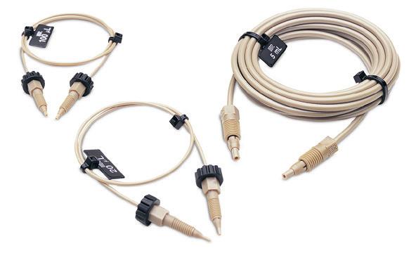
PEEK Sample Loops
Flexible PEEK sample loops are alternatives to stainless steel loops. PEEK loop ends are provided with clean, straight cuts for easy valve installation.
PEEK polymer is inert to almost all organic solvents and is biocompatible, giving PEEK loops added versatility. Natural PEEK is used for these sample loops. Like metal loops, the size designations of PEEK loops are nominal. The actual volumes can differ from the theoretical designations because of the tolerance of the tubing bore. Accuracy of large PEEK loops (0.8 mm, 0.030” bore) is about ±14%, intermediate loops (0.5 mm, 0.020”) ±21%, and small loops (0.2 mm, 0.007”) ±65%.
PEEK loops are also supplied with unswaged RheFlex® fittings but do not require the same swaging precaution. The fittings can reposition along the loop tubing when the fitting is reinserted in the ports for correct loop installation.
APPLICATION NOTE
Fluidic Movement in Tubes
Q: “Why can I load only up to half of the volume of the loop in partial-filling method?”
A: Sample occupies 2 µL of loop for every 1 µL loaded from the syringe. For example, 10 µL of sample spreads out over the entire length of a 20 µL loop. Any additional sample loaded will overflow the end of the loop and exit out to waste. Reproducibility is poor because the volume of sample in the loop is different from the known volume originally loaded by your syringe.
Fluid spreads in a parabolic shape through a tube instead of moving in one plug because the velocity is different at the center of the tube than at the walls. The velocity at the center of the tube is twice the average velocity, and near the wall the velocity is almost zero, creating a parabolic shape. This fluidic movement is called laminar flow. See Figure 1.
In dual mode injection valves (see “Sample Loop Loading” Application Note on page 131) the sample from the syringe needle loads directly into the sample loop. The sample volume is known since there is no sample waste. The laminar flow phenomenon accounts for the shape of the plot as shown in Figure 2. Note that the plot has three regions:
1 Partial-Filling Region. When the volume dispensed is less than half the loop volume, the curve is linear. Sample has not reached the end of the loop. Within this region, performance depends on the syringe and operator.
2 Nonlinear Region. When the volume dispensed is between half the loop volume and about two loop volumes, the curve is nonlinear. Sample is lost from the loop, so reproducibility is poor. If you dispense a volume equal to the loop size, you are in this region of poor performance.
3 Complete-Filling Region. When the volume of sample dispensed is several loop volumes, the loop contains only pure sample, undiluted by residual mobile phase. Within this region, reproducibility is highest.
In the single mode injection valves the sample must pass through a connecting passage before it reaches the sample loop. Since some of the sample dispensed from the syringe remains in the connecting passageway, an unknown amount enters the sample loop. Therefore, single mode injection valves achieve high reproducibility only by using the complete-filling method.
www.idex-hs.com Area of Peak Sample Dispensed (loop volumes) 1 2 3 4 40 80 linear nonlinear constant
area)
Sample Flow
Mobile
Figure 2 Sample mass (observed peak
vs. volume of sample dispensed from the syringe, in units of loop volumes,
injected
onto the column from our dual mode injector such as model 7725
Tube Wall
Phase
Figure 1 Schematic of sample flow through mobile phase between tubing walls
FLUIDICS VALVES VALVE ACCESSORIES PEEK SAMPLE LOOPS
128 FLUIDICS FLUIDIC CONNECTIONS VALVES DEGASSERS COLUMN HARDWARE OPTICS www.biotechfluidics.com

APPLICATION NOTE
PEEK Physical Strength Characteristics
Although PEEK material is compatible with virtually all solvents, there are many factors that affect burst pressure of PEEK tubing. Factors such as increases in inner diameter, temperature, exposure time, and concentration of organic solvents affect the degradation of PEEK. Other solvents such a THF, methylene chloride and DMSO cause PEEK tubing to swell while concentrated nitric acid and sulfuric acid weaken the tubing.
APPLICATION NOTE
How to Find and Fix Common Sample Injector Leaks
Leaks cause valuable sample loss. Nobody wants that. The key to the valve holding pressure is the integrity of the sealing surfaces. If there is a scratch on the sealing surface, or the needle seal in the rotor seal is damaged, a leak may appear. It is also important to realize what appears to be a leak can instead be a result of siphoning. The following are the three most common situations in which fluid leaks occur.
1 If fluid leaks out of the needle port only while loading the loop (i.e., while pushing down on the plunger of the syringe), the problem is most likely that the needle seal or the needle port fitting in the loop filler port is not gripping the syringe needle tightly enough. Tighten the needle seal grip by pushing with the eraser end of a pencil on the needle port (See Figure 1). The tightening reduces the hole diameter of the needle seal and port fitting.
2 If fluid leaks continuously from the needle port or vent lines and/or from the stator-tostator ring interface, replace the rotor seal and/or stator face assembly. Scratches on the rotor seal or cracks in the stator face assembly allow mobile phase to escape and cause cross port leakage. Genuine IDEX Health & Science RheBuild® Kits are listed on page 124.
3 If fluid leaks from the needle port and/or vent lines but eventually stops, the cause is most likely siphoning and not a leak. Siphoning occurs if the vent lines are lower or higher than the needle port. Adjust the vent line(s) so that the outlet is at the same horizontal level as the needle port to prevent siphoning. (See Figure 2).
For other leakage or injection troubleshooting, refer to our Troubleshooting Guide for HPLC Injection Problems. You may download the Guide from our web site: www.idex-hs.com under Education & Tools.
www.idex-hs.com FLUIDICS VALVES VALVE ACCESSORIES PEEK SAMPLE LOOPS
Figure 1 To reform the needle seal, push the eraser end of a pencil against the needle port
Figure 2 Needle port level compared to the level of vent line outlet:
(A) siphoning occurs when the vent line outlet is above the needle port level
129 FLUIDICS FLUIDIC CONNECTIONS VALVES DEGASSERS COLUMN HARDWARE OPTICS www.biotechfluidics.com
(B) siphoning does not occur if the vent line outlet is the same horizontal level as the needle port
PEEK Sample Loops (Cont.)
APPLICATION NOTE
Using Proper Syringe Needles
Needle
Needle port tube
Stator
Needle
With front-loading injection valves it is important to use the correct needle when loading the sample loop. An incorrect needle will damage the valve and can cause poor reproducibility. When the needle is too short the tip will not reach the needle seal. When the needle is too small in diameter the seal will not grip tightly enough. Needles with a beveled tip can damage the rotor seal and stator face assembly (see Figure 1). The needle should be #22 gauge (0.028”–0.0285”/ 0.72 mm), and 90° point style (square cut end). Model 3725i requires a #16 gauge (0.0645”–0.0655”/ 1.65 mm) needle. Never use a beveled, pointed, or tapered needle.
Needle specifications are not critical when using a Loop Filler Port to load the sample loop. However, it is important to tighten the needle port fitting around the needle if using a syringe needle with a slightly smaller diameter than 0.7 mm (0.028”).
If the loading method used is complete-filling, a syringe without a needle can be used. A syringe fitted with a Needle Port Cleaner can be used with a front-loading valve (Figure 2A) or with a Loop Filler Port (Figure 2B).
Needle port accessories are listed on page 132.


PEEK Sample Loops
PEEK LOOPS FOR 3725, 3725I INJECTION VALVES
PEEK LOOPS FOR 9725, 9010, PR/EV750-100, PR/EV753-100 INJECTION VALVES
9055-033
PEEK LOOPS FOR 7725, 7725I, PR/EV700-100
7123-227 1 µL Sample Loop (models PR/EV700-100 and EV750-100 only)
7755-015 2 µL Sample Loop (models 7725, 7725i, and 9725(i) only)
REPLACEMENT RHEFLEX FITTINGS FOR PEEK LOOPS
6000-078 Nut/Ferrule Set, Natural PEEK, 5/16-24, for 1/8” OD loops
6000-079 Obsolete Ferrules, Natural PEEK, for 1/8” OD loops
6000-251 Ferrules, Natural PEEK, for 1/16” OD loops
6000-254 Nut/Ferrule Sets, Natural PEEK, 10-32, for 1/16” OD loops
www.idex-hs.com FLUIDICS VALVES VALVE ACCESSORIES PEEK SAMPLE LOOPS
A
Figure 1 A square cut needle: (A) stops against the stator face assembly; The tip of a pointed needle (B) slips into the stator face and the tip breaks off as the valve rotates
Figure 2
B B Rotor seal
seal Needle
(A) Syringe fitted with Needle Port Cleaner (Part # 7125-054) loading a front-loading valve (model 7725); (B) loading a Loop Filler Port (Part # 7012)
Needle
port tube
A Rotor seal
Stator face assembly
seal
Needle
face assembly
Part No. Volume Tubing Valco No. Qty.
3055-018 2.0 mL Sample Loop 1.6 mm (0.062”) ID x 1/8” ODN/A ea. 3055-019 5.0 mL Sample Loop 1.6 mm (0.062”) ID x 1/8” ODN/A ea. 3055-023 10 mL Sample Loop 2.0 mm (0.080”) ID x 1/8” ODN/A ea. 3055-025 20 mL Sample Loop 2.0 mm (0.080”) ID x 1/8” ODN/A ea.
Part No. Volume Bore / Tubing Valco No. 9055-020 5.0 µL Sample Loop 0.18 mm (0.007”) ID x 1/16” ODSL5CWPK ea. 9055-021 10 µL
0.25 mm
ea. 9055-022 20
0.25 mm
ea.
50 µL
Loop 0.51 mm
ea. 9055-024 100 µL
0.51 mm
ea. 9055-025 200 µL Sample Loop 0.51 mm (0.020”)
1/16” ODN/A ea. 9055-026 500 µL Sample Loop 0.76 mm
1.0 mL
0.76
ea.
2.0 mL Sample Loop 0.76 mm
ea.
5.0 mL
0.76 mm
Sample Loop
(0.010”) ID x 1/16” ODSL10WPK
µL Sample Loop
(0.010”) ID x 1/16” ODSL20WPK
9055-023
Sample
(0.020”) ID x 1/16” ODSL50WPK
Sample Loop
(0.020”) ID x 1/16” ODSL100WPK
ID x
(0.030”) ID x 1/16” ODSL500WPK ea. 9055-027
Sample Loop
mm (0.030”) ID x 1/16” ODSL1KCWPK
9055-028
(0.030”) ID x 1/16” ODSL2KCWPK
9055-029
Sample Loop
(0.030”) ID x 1/16” ODN/A ea.
0.76 mm
Obsolete 10 mL Sample Loop
(0.030”) ID x 1/16” ODN/A ea.
Internal groove N/A ea.
Internal groove N/A ea.
ea.
5-pk
10-pk
10-pk
130 FLUIDICS FLUIDIC CONNECTIONS VALVES DEGASSERS COLUMN HARDWARE OPTICS www.biotechfluidics.com

Suction Needle Adapter
Our adaptable Loop Filler Ports (Part #7012 and 9012) are used to load sample from syringe needles or luer tips. The Needle Port (Part #9013) conserves sample by minimizing the volume between the needle and the valve.

Partial-Filling
Use the partial-filling method if you need to conserve sample, or if you want to vary sample volume frequently.
In partial-filling, the syringe sets the volume injected onto the column. There is no sample waste, and the volume injected onto the column is equal to that dispensed from the syringe. Reproducibility is 1.0% relative standard deviation (RSD). The volume of the sample loaded is limited to half the sample loop volume. For example, the most you can load into a 200 µL sample loop is 100 µL.
Complete-Filling
Use the complete-filling method if you have plenty of sample, if you do not vary sample volume, or if you need high reproducibility.
In complete-filling, the loop sets the volume loaded onto the column. Use excess sample (two to five loop volumes) to replace all the mobile phase in the loop. See Figure 2. Change the loop to vary the sample volume. Reproducibility is typically 0.1% RSD for loop sizes ≥ 5 µL. Accuracy is limited as loop volumes are nominal.
Q: “Which method should I use and which IDEX Health & Science sample injection valves use this method?”
A: There are two types of injection valves available: dual mode and single mode. Dual mode injection valves allow both partial- and complete-filling whereas single mode injection valves allow only complete-filling. See manual injection valves, page 123.
If you are collecting experimental data, sample is scarce, and/or you want to use different sample volumes, a dual mode injector with a large volume sample loop is appropriate. Only dual mode injection valves allow the partial-filling method for easily varying your volumes (up to half your sample loop volume) by setting the syringe volume. Once you begin routine analysis, and/or you have an abundance of sample, either a dual mode or single mode injector is appropriate. Both types of injection valves allow the complete-filling method in which you overfill the sample loop. Complete-filling maximizes the reproducibility of your results.
www.idex-hs.com
FLUIDICS VALVES VALVE ACCESSORIES SUCTION NEEDLE ADAPTER
9125-076
Part No. Description Qty. SUCTION NEEDLE ADAPTER & ACCESSORIES 7012 Obsolete Stainless Steel Loop Filler Port ea. 7125-054 Needle Port Cleaner ea. 9012 Obsolete PEEK Loop Filler Port ea. 9013 PEEK Needle Port ea. 9125-076 Suction Needle Adapter (for Models 7725 and 9725) ea. Flow path for the typical dual mode injector INJECT LOAD Waste Waste 4 5 Column Needle Port Waste 1 3 4 5 6 2 Needle Port Waste Pump Column APPLICATION NOTE Dual
7125-054
9013
Mode Sample Loop Loading: Partial-Filling vs. Complete-Filling
Waste Waste 1 3 4 5 6 2 Column Needle Port Pump Waste 1 3 4 5 6 2 Needle Port Waste Pump Column 131 FLUIDICS FLUIDIC CONNECTIONS VALVES DEGASSERS COLUMN HARDWARE OPTICS www.biotechfluidics.com

Wrenches, Brackets, & FittingsReplacement
Valve Wrenches
For convenient wrench-tightening of fittings on high pressure rotary shear valves
For removal of knobs on Manual Valves
The smartly designed IDEX Wrench is a double-ended slotted socket wrench that fits over 1/16” and 1/8” OD tubing. It easily loosens and tightens 1/4” and 5/16” hex head stainless steel or PEEK fittings. The “Z” shape of the IDEX Wrench provides ideal leverage for changing sample loops and fittings, and keeps one end from restricting the use of the other.
The V-103 is an Allen (hex-key) wrench designed to remove the knob from our V-101 valves (page 123). The V-104 is an Allen wrench that can be used to remove the knob from our Medium Pressure Selection and Injection Valves (also found on page 123).

Mounting Brackets
Our mounting brackets and panels of different shapes and sizes organize and provide a sturdy support for IDEX Health & Science valves. The Ring Stand Mounting Bracket now allows the valves to mount onto common laboratory equipment.
MXX Replacement Fittings
Use these replacement Ferrules and O-rings for 1/8” and 1/16” tubing with the MXX Series II valves shown on page 119. Please see the part number chart below for a list of individual part numbers.
www.idex-hs.com
Part No. Description Qty. VALVE WRENCHES 6810 IDEX Wrench ea. MOUNTING BRACKET ACCESSORIES 7160 Obsolete Mounting Panel ea. 7160-010 Obsolete Valve Angle Bracket ea. 7160-029 Ring Stand Mounting Bracket ea. VALVE BRACKET M-615-1 Obsolete Mounting Bracket for IDEX Health & Science Switching Valves ea. M-615-2 Obsolete Mounting Bracket for IDEX Health & Science Injection and Selection Valves ea. REPLACEMENT FITTINGS 7770-039 Ferrules for 1/8” OD Tubing 25-pk 7770-040 Obsolete Ferrules for 1/8” Tubing 50-pk 7770-044 Ferrules for 1/16” OD Tubing 25-pk 7770-124 O-rings for 1/16” OD Tubing 25-pk 7160-029 FLUIDICS VALVES VALVE ACCESSORIES WRENCHES, BRACKETS, & REPLACEMENT FITTINGS 133 FLUIDICS FLUIDIC CONNECTIONS VALVES DEGASSERS COLUMN HARDWARE OPTICS www.biotechfluidics.com
6810

FLOW REGULATING VALVES
Our Flow Regulating Valves include specifically designed valves that are used to control or stop the flow of a stream and are ideal for use if your application involves low frequency of use or demands operator control. A variety of types and styles of valves allow you to manage directional flow. In addition, we offer replacement cartridges for all of our flow regulating valves.
140
141
142
www.idex-hs.com
VALVES
135 CHECK
MICRO-SPLITTER VALVES
MICRO-METERING VALVES
SHUT-OFF VALVES FLUIDICS VALVES FLOW REGULATING VALVES 134 FLUIDICS FLUIDIC CONNECTIONS VALVES DEGASSERS COLUMN HARDWARE OPTICS www.biotechfluidics.com

Low cracking pressures
Less than 150 µL internal volume
Materials of construction: PEEK; perfluoroelastomer (CV-3001); gold-plated stainless steel spring (CV-3001); ethylene propylene (CV-3011); and stainless steel spring (CV-3011)
Inline CheckCartridge Valves
Our cartridge-style Inline Check Valves are designed to limit flow to one direction. These assemblies withstand system pressures of 1,000 psi (69 bar). The cracking pressures for the Inline Check Valve Cartridges are 1.5 psi (0.1 bar) for the CV-3001 and 3 psi (0.2 bar) for the CV-3011. Tolerance on the cracking pressure for CV-3001 is ± 0.5 psi (0.03 bar) and ± 1.5 psi (0.1 bar) on CV-3011.
cm)
CV-3000
Inline Check Valve Includes (1) CV-3001 Cartridge and Flangeless Fittings for 1/16” OD tubing
www.idex-hs.com
0.42” (1.07
1.92” (4.88 cm)
Part No. Description Includes Swept Volume Qty. INLINE CARTRIDGE CHECK VALVES CV-3000 Inline Check Valve Assembly for 1/16” OD tubing (1) CV-3001, (2) XP-21596 µL ea. CV-3001 Inline Check Valve Cartridge for CV-3000 91 µL ea. CV-3010 Inline Check Valve Assembly for 1/8” OD tubing (1) CV-3011, (2) XP-315 100 µL ea. FLUIDICS VALVES FLOW REGULATING VALVES CHECK VALVES INLINE CARTRIDGE CHECK VALVES 135 FLUIDICS FLUIDIC CONNECTIONS VALVES DEGASSERS COLUMN HARDWARE OPTICS www.biotechfluidics.com

Add back-flow protection to any 1/4-28 flat-bottom port
15 psi (1 bar) and 3 psi (0.2 bar) cracking pressure versions
Excellent chemical resistance
Materials of construction:
PEEK; PCTFE; perfluoroelastomer; PTFE (CV-3301 and CV-3302); stainless steel (CV-3301 and CV-3302); or gold-plated stainless steel (CV-3315 and CV-3316)
Standard 1/4-28 Inline Check Valves
Connect these Inline Check Valves to any 1/4-28 flat-bottom port. Then thread your 1/4-28 flat-bottom fitting into the check valve to connect the tubing. Once installed, the springactuated sealing system eliminates back flow, helping to prevent upstream contamination or damage. In addition, the unique design of this product eliminates the additional tubing cuts and connections required to install conventional inline check valves.
RELATED PRODUCTS
1/4-28 Inline Check Valves and Non-Metallic Check Valves with 1/4-28 flat-bottom ports (next page) can be used with any 1/4-28 Flangeless, Super Flangeless™, and VacuTight™ fitting on pages 45, 39, and 42, respectively, of the Fittings Chapter.
Micro-Volume Inline Check Valves and Non-Metallic Check Valves with 10-32 coned ports (next page) can be used with any 10-32 polymer Fingertight or SealTight™ fitting on page 36. Connect capillary tubing using the optional ferrules listed on page 35 or the NanoTight™ Fittings and Tubing Sleeves on page 37.
www.idex-hs.com
CV-3315 Standard, Inlet 1/4-28 FB Male to 1/4-28 FB Female 3 psi (0.2 bar) cracking pressure CV-3301 Standard, Inlet 1/4-28 FB Male to 1/4-28 FB Female 15 psi (1 bar) cracking pressure CV-3302 Standard, Outlet 1/4-28 FB Male to 1/4-28 FB Female 15 psi (1 bar) cracking pressure CV-3316 Standard, Outlet 1/4-28 FB Male to 1/4-28 FB Female 3 psi (0.2 bar) cracking pressure 0.49” (1.24 cm) 1.09” (2.77 cm) 0.49” (1.24 cm) 1.04” (2.64 cm) 0.49” (1.24 cm) 1.04” (2.64 cm) 0.49” (1.24 cm) 1.09” (2.77 cm) Part No. Description Cracking Pressure Qty. STANDARD 1/4-28 INLINE CHECK VALVES CV-3301 Inlet Check Valve, 1/4-28 FB, M to 1/4-28 FB, F* 15 psi (1 bar) ea. CV-3302 Outlet Check Valve, 1/4-28 FB, M to 1/4-28 FB, F* 15 psi (1 bar) ea. CV-3315 Inlet Check Valve, 1/4-28 FB, M to 1/4-28 FB, F* 3 psi (0.2 bar) ea. CV-3316 Outlet Check Valve, 1/4-28 FB, M to 1/4-28 FB, F* 3 psi (0.2 bar) ea. *
Male
threads;
Female
threads; C
Coned; FB
Flat-Bottom
M =
(external)
F =
(internal)
=
=
FLUIDICS VALVES FLOW REGULATING VALVES CHECK VALVES STANDARD 1/4-28 INLINE CHECK VALVES 136 FLUIDICS FLUIDIC CONNECTIONS VALVES DEGASSERS COLUMN HARDWARE OPTICS www.biotechfluidics.com

Cracking pressure of 8 psi (0.6 bar)
Excellent chemical resistance
Materials of construction: PEEK and perfluoroelastomer, suitable for biological applications
Non-Metallic Check Valves
Our Non-Metallic Check Valves are biocompatible and delivers a low cracking pressure. With a swept volume of only 7.4 μL, our Check Valve is perfect for applications where low flow path volume is critical, such as delivery to lab-on-a-chip, single-cell analysis and microor nano-LC post-column derivatization. Once installed, this check valve helps prevent back flow and the potential for contamination or damage to sensitive upstream equipment.
10-32 Micro-Volume Inline Check Valves
With a swept volume of only 7.4 µL, our 10-32 Micro-Volume Inline Check Valves are perfect for applications where low flow path volume is critical, such as delivery to lab-on-achip, single-cell analysis and micro- or nano-LC post-column derivatization. Once installed, this check valve helps prevent back flow and the potential for contamination or damage to sensitive upstream equipment.
NOTE
Check valves are specified by:
Cracking Pressure: the pressure required for the valve to open in the direction of the arrow.
Maximum Pressure: the maximum pressure the valve can experience in the reverse direction without leaking backwards.
Back Pressure Created: the amount of back pressure generated by the check valve with 50 mL/min room temperature water flowing in the direction of the arrow.
SPECIFICATIONS & DETAILS
www.idex-hs.com
CV-3500 Micro-Volume Inline 10-32 C Female to 10-32 C Female 0.62” (1.57 cm) 0.93” (2.36 cm)
Part No. Description Cracking Pressure Qty. NONMETALLIC 10-32 MICRO-VOLUME INLINE CHECK VALVE CV-3500 Inlet/Outlet Check Valve, 10-32 C, F to 10-32 C, F* 8 psi (0.6 bar) ea. * M = Male (external) threads; F = Female (internal) threads; C = Coned; FB = Flat-Bottom
Swept Volume Thru-Hole Max. Pressure Rating Back Pressure Created Cracking Pressure Tolerance STANDARD 1/4-28 FB CV-3301, CV-3302 20 µL 0.020” (0.50 mm)2,000 psi (138 bar)45 psi (3.1 bar) ± 5 psi (0.34 bar) CV-3315, CV-3316 16 µL 0.020” (0.50 mm)2,000 psi (138 bar)10 psi (0.7 bar)± 1.5 psi (0.10 bar) NONMETALLIC 10-32 CONED MICRO-VOLUME CV-3500 7.4 µL 0.010” (0.25 mm) 3,000 psi (207 bar) 25 psi (1.7 bar)± 5 psi (0.34 bar) FLUIDICS VALVES FLOW REGULATING VALVES CHECK VALVES NON-METALLIC CHECK VALVES 10-32 MICRO-VOLUME INLINE CHECK VALVES 10-32 Micro-Volume Inline Check Valves 137 FLUIDICS FLUIDIC CONNECTIONS VALVES DEGASSERS COLUMN HARDWARE OPTICS
Non-Metallic Check Valves (Cont.)
Low cracking pressure of 1 psi (0.07 bar)
Multiple configurations for different applications
Excellent chemical resistance
Materials of construction: PEEK and perfluoroelastomer
APPLICATION NOTE
The CV-3320 or CV-3321 style can be connected to any 1/4-28 flat-bottom port for trouble-free back flow protection.
When using a pump after the analytical column, consider placing a CV-3330 Check Valve after the column to prevent fluid from the post-column pump from flowing backwards through the column. This product also serves as an excellent nonmetallic alternative to our CV-3010 (page 135) in sparging applications where the mobile phase may be corrosive to the stainless steel or ethylene propylene components inside the CV-3010 assembly.
The CV-3335 Inlet and CV-3336 Outlet Check Valves allow tubing larger than 1/16” OD (up to 1/8”) to be connected into a 10-32 coned internal port. Use both of these check valves when attaching a larger-volume sample loop to an analyticalscale injection valve. This setup limits the flow of the sample into the loop to one direction, minimizing back flow and sample carry-over.
The CV-3340 is useful in virtually any high pressure fluid pathway using 1/16” or smaller OD tubing, where limiting the direction of flow is desirable.
1/4-28 & 10-32 Inline Check Valves
Our 1/4-28 & 10-32 Non-Metallic Inline Check Valves provide excellent backflow protection for sensitive equipment along with outstanding chemical resistance guaranteed by the PEEK polymer and perfluoroelastomer construction. Metal-free composition makes these check valves perfect for use with corrosive fluids or biological samples. These check valves function well up to moderately-high pressure applications. Low internal volume also allows them to be used in areas where flow path volume is important; however, higher flow rates can pass through with minimal pressure drop.
(1.57 cm) 1.09” (2.77 cm) CV-3320, CV-3322, CV-3324 Nonmetallic, Inlet
CV-3321, CV-3323, CV-3325 Nonmetallic, Outlet 1/4-28 FB Male to 1/4-28 FB Female
SPECIFICATIONS & DETAILS
CV-3323
CV-3325
NOTE
Upon initial use — or following a period of extended inactivity — the cracking pressure for these check valves may be somewhat higher than the stated cracking pressure.
1/4-28 & 10-32 Inline Check Valves
Inlet/Outlet Check Valve, 10-32 C, F to 10-32 C, F*
* M = Male (external) threads; F = Female (internal) threads; C = Coned; FB = Flat-Bottom
www.idex-hs.com FLUIDICS VALVES FLOW REGULATING VALVES CHECK VALVES NON-METALLIC CHECK VALVES 1/4-28 & 10-32 INLINE CHECK VALVES
Swept Volume Max. Pressure Rating Back Pressure Created Cracking Pressure Tolerance CV-3320, CV-3321 37 µL 2,000 psi (138 bar) 30 psi (2.1 bar) ± 0.5 psi (0.03 bar) CV-3330 34 µL 2,000 psi (138 bar) 30 psi (2.1 bar) ± 0.5 psi (0.03 bar) CV-3335,
49 µL 2,000 psi (138 bar) 30 psi (2.1 bar) ± 0.5 psi (0.03 bar) CV-3340 34 µL 2,000 psi (138 bar) 30 psi (2.1 bar) ± 0.5 psi (0.03 bar) CV-3322,
49 µL 2,000 psi (138 bar) 30 psi (2.1 bar) ± 0.5 psi (0.03 bar)
µL 2,000 psi (138 bar) 30 psi (2.1 bar) ± 0.5 psi (0.03 bar)
CV-3336
CV-3324,
182
Part No. Description Cracking Pressure Thru-Hole Qty. NONMETALLIC
INLINE CHECK VALVES CV-3320 Inlet Check Valve,
FB, M to 1/4-28 FB, F* 1 psi (0.07 bar) 0.020” (0.50 mm) ea. CV-3321 Outlet Check Valve, 1/4-28 FB, M to 1/4-28 FB, F* 1 psi (0.07 bar) 0.020” (0.50 mm) ea. CV-3322 Inlet Check Valve, 1/4-28 FB, M to 1/4-28 FB, F* 1 psi (0.07 bar) 0.040” (1.0 mm) ea. CV-3323 Outlet Check Valve, 1/4-28 FB, M to 1/4-28 FB, F* 1 psi (0.07 bar) 0.040” (1.0 mm) ea. CV-3324 Inlet Check Valve, 1/4-28 FB, M to 1/4-28 FB, F* 1 psi (0.07 bar) 0.060” (1.60 mm) ea. CV-3325 Outlet Check Valve, 1/4-28 FB,
1 psi (0.07 bar) 0.060” (1.60 mm) ea.
1 psi (0.07 bar) 0.020” (0.50 mm) ea. CV-3335 Inlet Check Valve, 1/4-28 FB, F to 10-32 C, M* 1 psi (0.07 bar) 0.020” (0.50 mm) ea.
Check Valve,
M* 1 psi (0.07 bar) 0.020” (0.50 mm) ea. CV-3340
1 psi
bar) 0.020” (0.50 mm) ea.
1/4-28 AND 10-32
1/4-28
M to 1/4-28 FB, F*
CV-3330 Inlet/Outlet Check Valve, 1/4-28 FB, F to 1/4-28 FB, F*
CV-3336 Outlet
1/4-28 FB, F to 10-32 C,
(0.07
0.62”
FB Male to 1/4-28 FB Female 0.62” (1.57 cm) 1.09” (2.77 cm) CV-3330 Nonmetallic, Inline 1/4-28 FB Female to 1/4-28 FB Female 0.62” (1.57 cm) 0.99” (2.51 cm) CV-3335
C Male 0.62” (1.57 cm) 1.17” (2.97 cm) CV-3336 Nonmetallic, Outlet 1/4-28 FB Female to 10-32 C Male 0.62” (1.57 cm) 1.17” (2.97 cm) CV-3340 Nonmetallic, Inline 10-32 C Female to 10-32 C Female 0.99” (2.51 cm) 0.62” (1.57 cm)
1/4-28
Nonmetallic, Inlet 1/4-28 FB Female to 10-32
138 FLUIDICS FLUIDIC CONNECTIONS VALVES DEGASSERS COLUMN HARDWARE OPTICS

Check valve protection with luer convenience
Remains open when engaged
Materials of construction: PEEK, perfluoroelastomer, and gold-plated stainless steel spring
RELATED PRODUCTS
1/4-28 Inline Check Valves and NonMetallic Check Valves with 1/4-28 flatbottom ports (next page) can be used with any 1/4-28 Flangeless, Super Flangeless™, and VacuTight™ fitting on pages 45, 39, and 42, respectively, of the Fittings Chapter.
Micro-Volume Inline Check Valves and Non-Metallic Check Valves with 10-32 coned ports (page 137) can be used with any 10-32 polymer Fingertight or SealTight™ fitting on page 36. Connect capillary tubing using the optional ferrules listed on page 35 or the NanoTight™ Fittings and Tubing Sleeves on page 37.
Quick-Stop Luer Inline Check Valve
The Quick-Stop Luer Check Valve is designed to provide inline luer connect/disconnect convenience without the mess and hazard of spills. Just connect the valve assembly to your inline tubing using standard 1/4-28 flat-bottom fittings (see pages 39 – 46). The check valve is automatically opened once the luer connection is engaged, allowing flow in either direction. Disconnecting the luer union causes the check valve to close. Please see the “Application Note” on this page for specific ideas regarding use of this valve.
APPLICATION NOTE
Inlet Solvent Reservoir:
Quickly change your solvent on the low pressure end of an HPLC system, while preventing potentially hazardous spills! Just install a Quick-Stop Luer Check Valve Assembly between your solvent reservoir and the pump, with the valve towards the bottle. The valve will prevent solvent leakage from the line coming from the reservoir, while the check valves in your pump prevent spills from the line leading to the pump. With both lines still full of solvent, this system also helps reduce the need to reprime your pump.
FIA Sample Injection:
The Quick-Stop Luer Check Valve provides a practical means to introduce a sample into FIA and other low pressure systems, when used in conjunction with a P-612 Pressure Relief Valve Tee (page 148). Simply connect the Tee into the appropriate flow path line with the included fittings and thread the P-697 Quick-Stop Luer Valve onto the 1/4-28 male end of the Tee. Sample can then be introduced conveniently by using a standard luer-tipped syringe. The check valve is automatically opened when the syringe is attached and closed when the syringe is removed.
Post Column Derivitization:
For post-column derivitization, place a CV-3000 Inline Check Valve on the effluent side of your column to prevent derivatizing agents from flowing backwards and poisoning the column. Placement on the post-column reagent line will also prevent mobile phase from contaminating the reagent if the auxiliary pump fails.
Helium Sparging Tank Protection:
Try the CV-3010 Assembly, designed specifically for degassing (sparging) lines to prevent solvent backup if the sparging gas runs out. This check valve will help prevent potential solvent cross-contamination and damage to the gas regulating valve.
www.idex-hs.com P-655 P-697 Part No. Description Includes Swept Volume Qty. QUICK-STOP LUER CHECK VALVE P-696 Quick-Stop Luer Check Valve Assembly (1) P-697, (1) P-655 127 µL ea. P-697 Quick-Stop Luer Check Valve 107 µL ea. P-699 Bulkhead Quick-Stop Luer Valve (1) nut/lock washer set107 µL ea.
FLUIDICS VALVES FLOW REGULATING VALVES CHECK VALVES QUICK-STOP LUER INLINE CHECK VALVE 139 FLUIDICS FLUIDIC CONNECTIONS VALVES DEGASSERS COLUMN HARDWARE OPTICS www.biotechfluidics.com

For interfacing LC-MS systems
Adjustable split stream flow rates
Versions for up to 800 psi (55 bar) and up to 4,000 psi (276 bar)
APPLICATION NOTE
With an incoming flow rate of 1 mL/min using room temperature water and equal pressures on both outlet lines, the minimum split flow rate is 2 µL/min for the standard micro-splitter valves and 4.8 µL/min for the high pressure micro-splitter valves.
All Micro-Splitter Valves have been tested at flow rates to 100 mL/min, with a maximum resulting pressure drop of only 45 psi (3.1 bar) when the valve is fully opened.
Micro-Splitter Valves
Our Micro-Splitter Valves are designed to accurately split and control a low-flow stream off a single incoming supply.
Choose between 1/4-28 flat-bottom and 10-32 coned threaded versions.
The High Pressure Micro-Splitter Valves are designed to operate successfully up to 4,000 psi (276 bar) and the standard Micro-Splitter valves are pressure rated to 800 psi (55 bar).
The Graduated Valve offers many of the benefits and features of Micro-Splitter Valves, plus the ability to adjust and set the split flow to repeatable settings. This allows documentation of settings and the resulting flow rates for easier method development. The graduations also make it easier to employ the valve in a system used to run multiple analyses that require different split flow rates.
P-450 Standard, 1/4-28, Biocompatible
Obsolete Standard, 10-32, Biocompatible
P-450
Standard Micro-Splitter Valve
(2.87 cm)
SPECIFICATIONS & DETAILS
Part No.Valve
P-450 Standard
P-451 Obsolete Standard10-32
P-460S, T Obsolete High Pressure10-321.2 / 2.8 µL
P-470 High Pres. Graduated 10-321.2 / 2.8 µL
1 The supply and waste port thru-holes have IDs of 0.020” (0.50 mm). The ID for the split-stream port thru-hole is 0.020” (0.50 mm) in standard versions; in capillary versions it is 0.010” (0.25 mm).
P-460S Obsolete High Pressure, 10-32, with Stainless Steel Needle
P-460T Obsolete High Pressure, 10-32, with Titanium Needle
GRADUATED MICRO-SPLITTER VALVES
P-470 High Pressure Graduated, 10-32, with Stainless Steel Needle
* Use with the MicroTight Tubing Sleeves, found on page 52.
www.idex-hs.com
Part No. Description Includes Qty. MICRO-SPLITTER
(3) XP-235 ea. P-451
(3) F-120 ea.
(3) F-120 ea.
VALVES
(3) F-120 ea.
(3) F-120 ea.
1.40” (3.56 cm)
Thumbscrew
1.13”
Threads Internal Volume1
open)Max. Operating Pressure
Type
(closed/fully
1/4-28 2.1
4.1 µL 800 psi (55 bar)
/
1.2
2.8 µL 800 psi
/
(55 bar)
4,000
psi (276 bar)
4,000
psi (276 bar)
FLUIDICS VALVES FLOW REGULATING VALVES MICRO-SPLITTER VALVES 140 FLUIDICS FLUIDIC CONNECTIONS VALVES DEGASSERS COLUMN HARDWARE OPTICS www.biotechfluidics.com

Flow rates as low as 3.5 µL/min*
1/4-28 flat-bottom and 10-32 coned designs available
Materials of construction: PEEK, PTFE
* At 1.0 mL/min incoming flow rate with room temperature water.
Micro-Metering Valves
For fine control of fluid flow rates, Micro-Metering Valves can reduce outgoing flow to as low as 3.5 µL/min*. These needle valves are perfect for use with peristaltic pump fluidtransfer applications, mass spectrometry, and fraction collection.
Our Micro-Metering Valves can also be used to regulate gas flow in helium sparging lines and as a flow-dependent variable back pressure regulator. For flow independent regulation of back pressure, please see page 147.
Flow path materials are PEEK polymer and PTFE. All versions of this valve have 0.020” (0.50 mm) thru-holes.
APPLICATION NOTE
Back Pressure Considerations
The Micro-Splitter Valves are designed to work when both effluent flow path pressures are nearly identical. However, the split flow path will often have higher back pressure than the waste flow path, making it hard to achieve any split flow at all. There are two possible solutions. Place a back pressure regulator (page 143) on the waste flow path that is equal to or slightly greater than the pressure on the split flow path. Or, switch the two effluent pathways such that the split flow pathway is attached to the “waste” port on the valve and the waste flow pathway is attached to the “split” port on the valve. (Please Note: This second method may result in a loss of adjustment sensitivity.)
Multi-Column and Detector Systems
Does your work require analyses with multiple columns and detectors that use the same mobile phase? If so, install one of our High Pressure Micro-Splitter Valves after your injector. A single injection can then be split to two separate columns and detector systems, at two different flow rates. This economical set-up eliminates the need for an additional pump and injector valve, while allowing data to be obtained simultaneously.
Post-Detector Interfacing
Use a Standard Micro-Splitter Valve to route fluid exiting an initial detector to other devices, such as a mass spectrometer and a fraction collector. The valve will split and reduce the flow rate to that required for MS interfacing, while diverting the remainder of the flow to the collector (a back pressure regulator may also be required for this set up, available on page 143).
Other Applications
These valves are also suited for other applications, such as adapting a standard HPLC system to handle microbore analyses. For more information and plumbing diagrams for this application and those listed above, please contact your local distributor or IDEX Health & Science directly.
* Maximum internal volume, with valve fully open.
www.idex-hs.com Part No. Material OD Tubing Thru-hole Internal Volume* Includes Qty. MICRO-METERING VALVES P-445 PEEK, Black 1/16” 0.020” (0.50 mm) 7.7 µL (2) XP-230 ea. P-446 PEEK, Black 1/16” 0.020” (0.50 mm) 7.2 µL (2) F-120 ea. P-447 PEEK, Black 1/8” 0.020” (0.50 mm) 7.7 µL (2) XP-330 ea.
PEEK
0.73” (1.85 cm) 1.28” (3.25 cm)
P-445
1/4-28 threaded
Micro-Metering Valve
0.49” (1.24 cm) OUT IN FLUIDICS VALVES FLOW REGULATING VALVES MICRO-METERING VALVES
Thumbscrew
141 FLUIDICS FLUIDIC CONNECTIONS VALVES DEGASSERS COLUMN HARDWARE OPTICS www.biotechfluidics.com

Biocompatible, all-polymer flow path
Available for 1/16” and 1/8” OD tubing
Pressure rated to 500 psi (34 bar)
Shut-OffValves
Stop a flow stream quickly with IDEX Health & Science biocompatible Shut-Off Valves. The bodies are manufactured from ETFE, and a PEEK rotor, making them highly resistant to chemical attack. The blue colorant used in some valve configurations has proven not to leach out with common HPLC solvents.
Connect semi-rigid or rigid tubing, such as PEEK, stainless steel or fluoropolymer, with the 1/4-28 Flangeless Fittings provided. Soft tubing, such as PharMed® or Tygon® (see page 14), may be connected to these valves using our 1/4-28 barbed adapters, found on page 90.
Maximum internal volume, with valve fully open.
www.idex-hs.com
ETFE body Shut-Off Valve 0.145” (0.37 cm) diameter 0.50” (1.27 cm) Part No. Material OD Tubing Thru-hole Internal Volume* Includes Qty. SHUT-OFF VALVES, BIOCOMPATIBLE P-721 ETFE body, PEEK rotor black 1/8” 0.040” (1.0 mm) 10.0 µL (2) P-335, (2) P-300N ea. P-732 Obsolete PEEK, Natural 1/16” 0.020” (0.5 mm) 2.5 µL (2) XP-235 ea. P-733 Obsolete PEEK, Natural 1/8” 0.040” (1.0 mm) 10.0 µL (2) XP-335 ea.
ETFE body, PEEK rotor black 1/16” 0.020” (0.5 mm) 2.5 µL (2) XP-235 ea. P-783 ETFE body, PEEK rotor black 1/8” 0.040” (1.0 mm) 10.0 µL (2) XP-335 ea. *
FLUIDICS VALVES FLOW REGULATING VALVES SHUT-OFF VALVES 142 FLUIDICS FLUIDIC CONNECTIONS VALVES DEGASSERS COLUMN HARDWARE OPTICS www.biotechfluidics.com
P-783
P-782
Black

BACK PRESSURE REGULATORS
Back Pressure Regulators (BPR) are designed to enhance system performance through outgassing prevention and improved pump check valve efficiency. It includes 5 and 20psi assemblies (replacement cartridges not available), a variety of pressure rated cartridges and assemblies, PEEK and stainless steel BPR holders, high pressure adjustable BPR for pressure between 2000 and 5000psi and ultra-low volume BPRs set to 100 and 500psi.
144 ULTRA-LOW VOLUME BACK PRESSURE REGULATOR
145 BACK PRESSURE REGULATOR ASSEMBLIES
146 BACK PRESSURE REGULATOR HOLDERS
147 BACK PRESSURE REGULATOR CARTRIDGES
148 PRESSURE RELIEF VALVES
www.idex-hs.com
FLUIDICS VALVES BACK PRESSURE REGULATORS 143 FLUIDICS FLUIDIC CONNECTIONS VALVES DEGASSERS COLUMN HARDWARE OPTICS www.biotechfluidics.com

Ultra-Low Volume Back Pressure Regulators (BPRs)
Wetted flow path materials: PEEK, perfluoroelastomer, and ETFE
Available pressure settings of 100 or 500 psi (7 or 34 bar)
Low swept volume of only 6 µL
Our Ultra-Low Volume Back Pressure Regulators (BPRs) were developed to minimize swept volume, which is especially important for multi-detector applications. With a maximum swept volume of only 6 µL*, it is nearly impossible to detect these BPRs as part of your fluid pathway. To minimize the swept volume added to your flow path, we recommend trimming the length of the attached tubing. And because the flow path is completely polymeric, you are assured of biocompatibility.
MicroVolume BPR Assembly Attached tubing not shown
Please Note: Our Ultra-Low Volume Back Pressure Regulators cannot be used as check valves due to their unique internal design. Try our Micro-Volume Inline Check Valve on page 137.
* The maximum internal swept volume listed above is for the back pressure regulator only and does not include the volume of the attached tubing lines.
SPECIFICATIONS & DETAILS
1 All data generated using water at room temperature.
2 Set at a flow rate of 0.5 mL/min.
3 Set at a flow rate of 5 mL/min.
www.idex-hs.com M-410
0.81” (2.06 cm) 1.30” (3.30 cm) Part No. Description Pressure Setting Tubing OD Includes Swept Volume Qty. ULTRA-LOW VOLUME BPRs M-410 Low Flow 100 psi (7 bar) 1/16” XP-2306 µL ea. M-412 Low Flow 500 psi (34 bar) 1/16” XP-2306 µL ea. M-420 High Flow 100 psi (7 bar) 1/16” XP-2306 µL ea.
Back Pressure Setting psi (bar) Flow Rate Recommendations Recommended Pressure Range psi (bar) 1/16” OD Tubing M-410 100 2 (7)2 Optimal: 100 µL–1 mL/min Max.: 4 mL/min 40–150 (3–10) PEEK, 0.010” ID M-412 500 2 (34)2 Optimal: 100 µL–1 mL/min Max.: 4 mL/min 250–525 (17–36) PEEK, 0.010” ID M-420 100 3 (7)3 Optimal: 3–8 mL/min Max.: 10 mL/min 40–150 (3–10) PEEK, 0.020” ID
FLUIDICS VALVES BACK PRESSURE REGULATORS ULTRA-LOW VOLUME BACK PRESSURE REGULATORS
144 FLUIDICS FLUIDIC CONNECTIONS VALVES DEGASSERS COLUMN HARDWARE OPTICS www.biotechfluidics.com

Flangeless Nut
Flangeless Ferrule Cartridge Holder Cartridge
Color-Coded End Cap


Back Pressure Regulator Assemblies
Choose from our line of Biocompatible and Stainless Steel BPR Assemblies, each complete with a replaceable, factory preset cartridge (except the 5 and 20 psi versions).
Our BPR Assemblies create incremental back pressures ranging from 5 to 1,000 psi (0.3 to 69 bar). The Biocompatible BPR Assemblies feature a PEEK holder; polymer-based fittings; biocompatible BPR cartridges and wrenches for tightening. Stainless Steel BPR Assemblies feature the same biocompatible BPR cartridges with a 316 stainless steel holder and polymer fittings.
In
High Pressure Adjustable Back Pressure Regulator
Materials of construction: PEEK, perfluoroelastomer, and PTFE
The biocompatible P-880 High Pressure Adjustable BPR offers the flexibility to adjust your system back pressure between 2,000 and 5,000 psi (138 and 345 bar), independent of the flow. Only 10% fluctuation in pressure generally occurs with flow rates of 0.1–10 mL/min. Lower or higher flow rates will lead to greater fluctuations in pressure. To achieve the desired back pressure setting, simply turn the thumbscrew while monitoring your system pressure. Because this product creates such high back pressure, please check system component specifications prior to using to avoid damaging any sensitive components.
P-880
High Pressure Adjustable BPR Includes One-Piece Fingertight Fittings for 1/16” OD tubing
www.idex-hs.com
U-609 500 psi BPR shown with
0.43” (1.09 cm) 1.04” (2.64 cm)
5 psi BPR (sold as assembly only) 1.92” (4.88 cm) 0.42” (1.07 cm)
Each BPR Assembly includes a preset BPR Cartridge and IDEX Health & Science fittings for 1/16” OD tubing.
P-765 Cartridge
P-790
Part No. Pressure Setting Holder Material Includes Swept Volume Qty. BPR ASSEMBLIES P-790 5 psi (0.3 bar) PEEK (2) XP-215 134 µL ea. P-791 20 psi (1.4 bar) PEEK (2) XP-215 134 µL ea. P-785 40 psi (2.8 bar) PEEK (1) P-761, (2) XP-215 131 µL ea. P-786 75 psi (5.2 bar) PEEK (1) P-762, (2) XP-215 131 µL ea. P-787 100 psi (7 bar) PEEK (1) P-763, (2) XP-215 131 µL ea. P-788 250 psi (17 bar) PEEK (1) P-764, (2) XP-235 102 µL ea. P-789 500 psi (34 bar) PEEK (1) P-765, (2) P-250, (2) LT-115 96 µL ea. P-455 1,000 psi (69 bar) PEEK (1) P-796, (2) P-250, (2) LT-115 89 µL ea. U-605 40 psi (2.8 bar) SST (1) P-761, (2) XP-201 129 µL ea. U-606 75 psi (5.2 bar) SST (1) P-762, (2) XP-201 129 µL ea. U-607 100 psi (7 bar) SST (1) P-763, (2) XP-201 129 µL ea. U-608 250 psi (17 bar) SST (1) P-764, (2) XP-201 99 µL ea. U-609 500 psi (34 bar) SST (1) P-765, (2) XP-201 93 µL ea. U-610 750 psi (52 bar) SST (1) P-795, (2) P-250, (2) LT-115 91 µL ea. HIGH PRESSURE ADJUSTABLE BPR ASSEMBLY P-880 2,000–5,000 psi (138-345 bar) (2) F-120BLK 9 µL ea. FLUIDICS VALVES BACK PRESSURE REGULATORS BACK PRESSURE REGULATOR ASSEMBLIES
0.73” (1.85 cm) 1.08” (2.74 cm)
1.90” (4.83 cm) 145 FLUIDICS FLUIDIC CONNECTIONS VALVES DEGASSERS COLUMN HARDWARE OPTICS www.biotechfluidics.com
Out

Back Pressure Regulator Holders
P-465 PEEK and U-469 Stainless Steel BPR Holders work with any of our replacement BPR Cartridges. Each holder comes with fittings for 1/16” OD tubing (see below). The U-469 Holder is surface-treated to prevent galling, a potential problem with large, threaded metal parts.
Please Note: These Back Pressure Regulator Holders are designed to allow each cartridge to operate at its stated pressure setting when tightened to 20 in–lbs. of torque. To approximate this level of torque, first finger tighten the Holder, then tighten an additional 1/8 –1/4 turn with the supplied wrenches.

* Using PEEK tubing and supplied fittings. ** Using stainless steel tubing and supplied fittings.
www.idex-hs.com
Pressure
Rating3,000 psi (207 bar)*
Pressure
Rating4,000 psi (276 bar)**
U-469
Stainless Steel BPR Holder (cartridge sold separately)
F-300
Two-Piece Fingertight Fitting (page 35)
P-465
PEEK BPR Holder (cartridge sold separately)
LT-115 LiteTouch® Nut (page 38)
P-250
Super Flangeless™ Ferrule (page 39)
Part No. Pressure Setting Holder Material Includes Swept Volume Qty. BPR HOLDERS P-465 Biocompatible BPR PEEK (2) P-250, (2) LT-115 7 µL ea. U-469 High Pressure BPR SST (2) F-300 4 µL ea. FLUIDICS VALVES BACK PRESSURE REGULATORS BACK PRESSURE REGULATOR HOLDERS 146 FLUIDICS FLUIDIC CONNECTIONS VALVES DEGASSERS COLUMN HARDWARE OPTICS www.biotechfluidics.com

APPLICATION NOTE
Small gas bubbles often form as solvent moves from the high pressure of an HPLC column to the low pressure environment leading to the detector. This outgassing can cause erratic baseline readings and loss of sensitivity. Placing a BPR (usually a 40–100 psi) after the detector provides an excellent, low-cost method for reducing this problem by maintaining enough back pressure on the mobile phase to keep gases dissolved in solution.
A back pressure regulator can also be used as a pump preload for low and fluctuating pressure applications. Many of today’s pumps require a steady back pressure to function properly. Install an IDEX Health & Science BPR (usually 500–1,000 psi) between the pump and the injector to enhance pump performance.
Caution: Do not exceed the maximum operating pressure of your system — please refer to the operating manuals for your system components before choosing the appropriate BPR.
Back Pressure Regulator Cartridges
Proven outgassing protection
Flow-independent pump preload for greater pump efficiency
5 to 1,000 psi cartridges and assemblies available
Back Pressure Regulators are designed to enhance system performance through outgassing prevention and improved pump check valve efficiency.
IDEX Health & Science back pressure regulators include:
5 and 20 psi assemblies (replacement cartridges not available)
40, 75, 100, 250, 500, 750, and 1,000 psi cartridges and assemblies
PEEK and stainless steel BPR holders
High pressure adjustable BPR for pressures between 2,000 and 5,000 psi
Ultra low volume BPRs set to 100 and 500 psi (page 144)
For flow control options try the Micro-Metering Valves found on page 141.
Back Pressure Regulator Replacement Cartridges
Materials of construction: PEEK, ETFE, perfluoroelastomer, and gold-plated stainless steel
These replacement cartridges will operate in any of the standard BPR holders shown on this page. These cartridges create back pressures from 40 to 1,000 psi (2.8 to 69 bar)—all independent of flow except as noted below.
The recommended operating flow rate range for our BPR Cartridges is 0.1 mL–10 mL/ min. Within this range, the amount of back pressure created by the BPR Cartridges and Assemblies will not vary more than ±10%. Lower or higher flow rates may result in larger pressure fluctuations.
www.idex-hs.com
Part No. Pressure Setting COLOR CODING Swept Volume Qty. BodyEnd-Cap BPR CARTRIDGES P-761 40 psi (2.8 bar) Tan Blue 125 µL ea. P-762 75 psi (5.2 bar) Tan Yellow 125 µL ea. P-763 100 psi (7 bar) Tan Red 125 µL ea. P-764 250 psi (17 bar) Tan White 95 µL ea. P-765 500 psi (34 bar) Tan Green 89 µL ea. P-795 750 psi (52 bar) BlackBlue 87 µL ea. P-796 1,000 psi (69 bar) BlackGreen 83 µL ea.
40 psi BPR Cartridge P-796 1,000 psi BPR Cartridge
P-761
FLUIDICS VALVES BACK PRESSURE REGULATORS BACK PRESSURE REGULATOR CARTRIDGES 147 FLUIDICS FLUIDIC CONNECTIONS VALVES DEGASSERS COLUMN HARDWARE OPTICS www.biotechfluidics.com

Pressure Relief Valves
Prevent system over-pressurization
Our Pressure Relief Valves are ideal for preventing system over-pressurization. These products protect system components by diverting fluid flow automatically when inline pressure exceeds the set limit. Choose between preset 100 psi (7 bar) and 5 psi (0.3 bar) assemblies, both shipped with Flangeless Fittings. The 100 psi version is a good, general purpose valve, while the 5 psi version is perfect for protecting syringe and peristaltic pump systems. The void volume of both relief valves is low due to the small 0.020” (0.50 mm) thru-holes in the valve tee body.
If you wish to have the Pressure Relief Valve open at a different pressure than 5 or 100 psi, simply combine one of the other replacement Back Pressure Regulator Assemblies listed on page 145 with the P-612 Pressure Relief Valve Tee. Choose the P-612S for larger bore tubing and higher flow applications.
www.idex-hs.com
Pressure Relief Valve Tee Includes Flangeless Fittings for 1/16” OD tubing (Drawing is not actual size)
P-612
Pressure Relief Valve Includes Flangeless Fittings for 1/16” OD tubing (Drawing is not actual size) 1.0” (2.54 cm) 2.50” (6.35 cm) Part No. Description Pressure Setting Tubing OD Includes Swept Volume Qty. PRESSURE RELIEF VALVES U-455 Pressure Relief Assembly 5 psi (0.3 bar) 1/16” XP-201 148 µL ea. U-456 Pressure Relief Assembly 100 psi (7 bar) 1/16” XP-201, wrenches139 µL ea. P-612 Pressure Relief Tee Only 1/16” XP-201 14 µL ea. P-612S Obsolete Pressure Relief Tee Only 3/16” XP-201 348 µL ea.
U-455
FLUIDICS VALVES BACK PRESSURE REGULATORS PRESSURE RELIEF TEES 148 FLUIDICS FLUIDIC CONNECTIONS VALVES DEGASSERS COLUMN HARDWARE OPTICS www.biotechfluidics.com
