
Product Cata log
2023/2024


Product Cata log
2023/2024


Material: ADC12
Follows: Face milling
Tool:
XEBEC Brush Surface A11-CB100M, p. 7
VIDEO

Material: ADC12
Follows: Face milling
Tool:
XEBEC Brush Surface A32-CB25M, p. 7
VIDEO

Material: Ceramics
Follows: Face milling
Tool:
XEBEC Brush Surface A11-CB15M, p. 7
VIDEO

Material: SCM
Follows: Drilling
Tool:
XEBEC Brush Crosshole CH-A12-7M-TL, p. 11
VIDEO

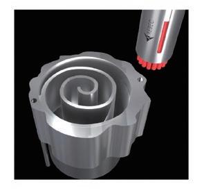
Material: Aluminum
Follows: Ball end milling
Tool:
Material: Aluminum
Follows: Face milling
Tool:
XEBEC Brush Surface A11-CB40M, p. 7
VIDEO

Material: S45C
Follows: Gear hobbing
Tool:
XEBEC Brush Surface A32-CB40M, p. 7
VIDEO

Material: SKD11
Follows: End milling
Tool:
XEBEC Brush Surface A32-CB25M & A11-CB25M, p. 7
VIDEO
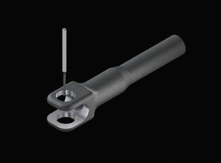
Material: SCM
Follows: Drilling
Tool:
Back Burr Cutter & Deburring
Tool Path, XC-58-A, p. 27
VIDEO
XEBEC Brush Surface End Type A11-EB06M, p. 9
VIDEO

Material: FCD
Follows: Drilling
Tool:
Back Burr Cutter & Deburring
Tool Path, XC-78-A, p. 27 VIDEO

Material: FCD
Follows: Drilling
Tool:
Back Burr Cutter & Deburring
Tool Path, XC-38-A, p. 27
VIDEO

Material: CFRP
Follows: Tapping
Tool:
Burrless Chamfering Cutter XC-C-06-N, p. 33
removal CNC deburring of input shaft CNC deburring of differential case
Material: FC250
Follows: Face milling
Tool:
XEBEC Brush Surface
A32-CB60M, p. 7
VIDEO

Material: Aluminum
Follows: End milling
Tool:
XEBEC Brush Surface A21-CB25M, p. 7

Material: SPHC
Follows: Turning
Tool:
XEBEC Brush Surface A21-CB25M, p. 7
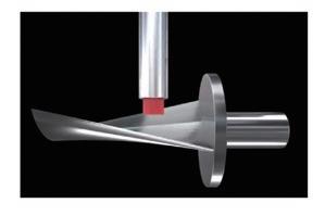
Material: SUS630
Tool:
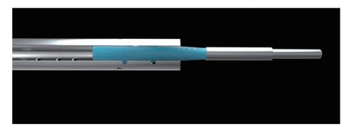
Material: Stainless steel
Follows: Drilling
Tool:
XEBEC Brush Crosshole CH-A33-7M, p. 11
VIDEO
VIDEO
VIDEO

Material: SCM
Follows: Threading
Tool:
XEBEC Brush Wheel Type W-A11-50, p. 15
VIDEO
Follows: Ball end milling
XEBEC Brush Surface A32-CB25M & A11-CB25M, p. 7
VIDEO

Material: Aluminum
Follows: Drilling
Tool:
XEBEC Stone Flexible Shaft CH-PM-6B, p. 37
VIDEO

Material: Aluminum
Follows: Casting
Tool:

Material: CoCrMo
Follows: Turning
Tool:
XEBEC Brush Surface A13-CB06M, p. 7
VIDEO

Material: Titanium
Follows: End milling
XEBEC Stone Mounted Point AX-PM-6T, p. 39
VIDEO

Tool:
XEBEC Brush Surface End Type A11-EB06M, p. 9
VIDEO
Material: PEEK resin
Follows: End milling
Tool:
Back Burr Cutter & Deburring
Tool Path, XC-18-A, p. 27
VIDEO
CNC deburring of gearbox CNC deburring of slide cylinder CNC roughing of brake disc CNC deburring of pipe CNC deburring of shaft CNC polishing of turbine blade Manual deburring of hydraulic manifold Manual deburring of shaft CNC polishing of artificial hip joint CNC deburring of osteosynthesis screw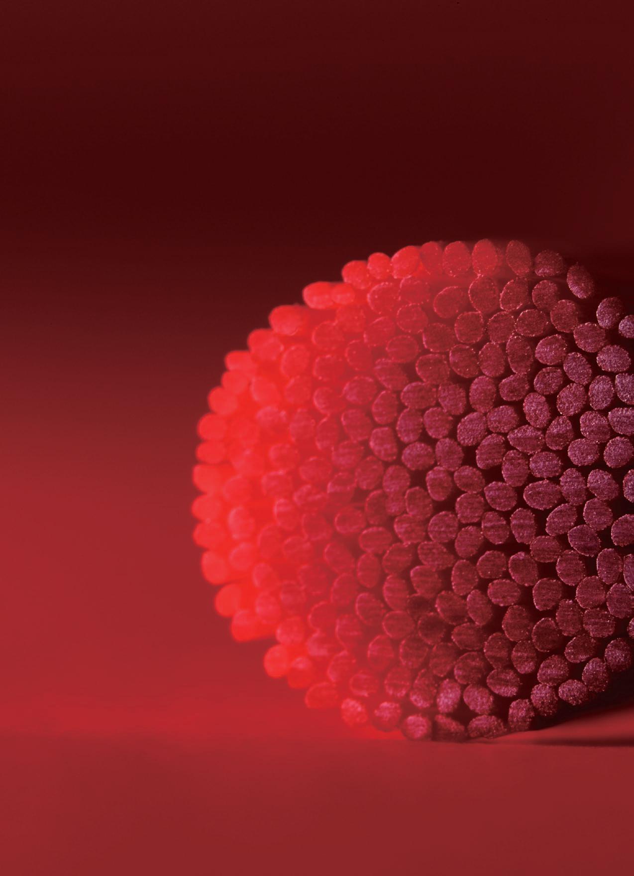
“What if we could make a brush out of the same material as ceramic grinding stones. It would be truly groundbreaking!” And so, the ceramic brush was born. It was one of a kind; the result of a desire to challenge technological norms. Yet no one quite understood what it could be used for. Some forward-thinking users believed in its potential. Thanks to them, we found out it could remove fine burrs and improve surface roughness at the same time. They also found it easy to manage compared with conventional brushes. This resulted in us pioneering the concept of automated deburring and polishing.
XEBEC Brush uses unique abrasive ceramic fiber material instead of abrasive grain. Each bristle consists of 1,000 ceramic fibers that work as cutting edges. Overwhelming grinding power, consistent cutting performance, and no deformation enables CNC deburring immediately after machining operations inside the same machine tool.
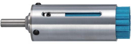


The content ratio of ceramic fiber is approximately 80%. Cutting edges on the brush tips offer excellent grinding power.
Maintains its straight shape and does not spread out like an old toothbrush. Easy to manage on mass production lines.
Before


New cutting edges are always exposed. Consistent grinding performance throughout due to the uniform structure of the fiber.
Brush selection
Resin Copper, Brass Aluminum
Steel
Workpiece material
Burr size
Stainless steel
HRSA steel
Cast iron
Hard material
Micro fine burrs
Burr thickness (≤ 0.1 mm)
Burr thickness (0.1 - 0.2 mm)
Brush (color) A13 (pink) A11 (red) A21 (white) A32 (blue)
Grinding power High
Not all brush colors are available in all sizes.
HRSA (heat resistant super alloy)
The high grinding power of ceramic fiber makes this tool optimal for polishing. Achievable surface roughness is Ra = 0.1 μm (Rz = 0.4 μm).
XEBEC Brush (A21-CB40M)
3000 min-1
Brass
Deburring

Before After


Polishing Before After
Patented
Deburring, cutter mark removal, and surface polishing

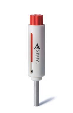
Applicable equipment

This tool can be mounted on equipment shown below.
Machining center Lathe (with live tools) Dedicated machine Robot
Brushes
Applicable burr size
Burr thickness ≤ 0.2 mm (Burrs this size can be bent by fingernails)
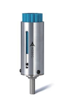
Tool composition
Brush and sleeve are sold separately. Assemble brush and sleeve before use.
Burr thickness
Bristle bundles are embedded in a single line on the periphery (except for φ6 type).
Brush size is approximate as the tip expands with rotation.
Brushes larger than φ100 are available by special order. Refer to page 10.
Sleeves
Overall length L is sleeve length not including brush projecton.
The case of the S15M-P is made of fiber-reinforced plastic (FRP).
Brush Sleeve
Higher quality automated deburring
Cylinder head

Material: Aluminum
Follows: Face milling
Tool: A11-CB100M
Rotational speed
Before
Abrasive nylon brush was used. It was time-consuming and not able to remove all burrs.
After
All burrs are removed by high grinding power. Quality is stable. The cycle time is shortened by a high feed rate.
Automation of time-consuming polishing

Material: Hard material
Follows: End milling
Tool: A11-CB25M
Feed rate - Deburring
Before
40 minutes hand polishing per workpiece. Uneven quality resulted in complaints.
After
Shortened the polishing time to one minute per workpiece by automation. Achieved uniform polishing quality.
Recommended parameters differ depending on brush size. Refer to the chart below for starting parameters for each brush size.
Burr thickness: 0.05 mm
(Very easily bent by fingernails)
Burr thickness: 0.1 mm
(Easily bent by fingernails)
Feed rate - Polishing
Rotational direction
Set the rotational direction so that the brush pushes the burrs up from below.
Upcut against burrs from below
4000 mm/min
2500 mm/min
Cutter mark removal, polishing 250 - 850 mm/min
Depth of cut - Vertical burrs
Formed by end milling & drilling
(Are vertical to brush tip) 0.5 mm
Depth of cut - Horizontal burrs
Formed by face milling
(Are horizontal to brush tip) 1.0 mm
Depth of cut - Polishing
Cutter mark removal, polishing 0.3 - 0.5 mm
Plastic workpieces may deform or discolor. If this occurs, reducing rotational speed to approximately 10% of the starting parameter may solve the problem.
Cutter mark removal and polishing on sealing surfaces


Applicable equipment
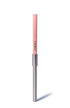
This tool can be used with equipment that controls rotational speed.
Brushes
Brush size is approximate as the tip expands with rotation.
Precautions for use
The grinding load must less be than 2 N for hand use.
The brush will break if:
• used beyond the maximum rotational speed
• used beyond the maximum indentation load
• used with a pneumatic rotary tool
Applicable burr size
Burr thickness ≤ 0.1 mm (Burrs this size can be easily bent by fingernails)

Tip angle approx. 100 deg.
Deburring, cutter mark removal, surface polishing (≥ 100 mm)

Applicable equipment
This tool can be mounted on equipment shown below.
Tool composition
Machining center Lathe (with live tools) Dedicated machine
Brushes
Brush size is approximate as the tip expands with rotation.
Slide rings
The slide ring consists of a ring, base holder and shank.
Combined weights of brushes and slide rings
Starting parameters
Applicable burr size VIDEO
Burr thickness ≤ 0.2 mm (Burrs this size can be bent by fingernails)
Burr thickness Burr height
The brush main unit and slide ring are separate items. Assemble the main unit and slide ring before use.
Brush Slide ring
• Ring
• Base holder
• Shank
Base holder and shank sizes are the same for all brush diameters. Ring size varies with brush diameter.
Applicable burr size
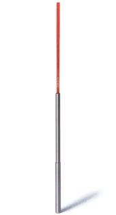

Applicable equipment

Deburring, cutter mark removal, polishing on inner diameters & counterbores (≤ φ20 mm)
Burr thickness ≤ 0.1 mm (Burrs this size can be easily bent by fingernails)
Burr thickness


This tool is used on equipment with rotational speed control (> 6500 min-1).
Brushes
Brush size is approximate as the tip expands with rotation.
Precautions for use
The shank must be inserted ≥ 30 mm in the holder to secure it properly.
The brush will break if:
• used beyond the maximum rotational speed
• used with a pneumatic rotary tool
• rotated outside of the bore (outside workpiece)
• used with brush tip < 20 mm inside bore
The brush may break when used with:
• off-center or angled crossholes
• t-shaped holes, when secondary bore diameter ≥ main bore
• crossholes, when secondary bore diameter ≥ 70 % main bore
Automation of crosshole deburring
Input shaft

Material: SCM
Follows: Drilling
Tool: CH-A12-7M-TL
Before
Manual deburring by abrasive nylon brush. Not all burrs were removed and output was low.
After
A dedicated machine is used to automate deburring. All burrs are removed by high grinding power. Quality is stable.
Automation of crosshole deburring
Valve case

Material: Resin
Follows: Drilling
Tool: CH-A12-5M-TL
Before
Manual deburring by cutter was time-consuming. Cutter left scratches on inner surface.
After
Deburring inside the machine reduced cycle time significantly. No scratching on inner surface and finish quality is stable.
Caution: Rotating the brush outside of the bore may damage the brush and cause injury to the operator.
1. Insert the brush stationary into the bore.
2. Rotate the tool once past the crosshole.
3. Machine while pulling the brush back.
4. Machine while pushing the brush forward.
5. Stop the brush rotation.
NG
6. Remove the brush when it is stationary.
Rotational
CH-A12-1.5M
CH-A12-3M-TL/3L-TL
5 4 3.5 10000 11000 12000 9000 13000 7 8 6 5 8000 9000 10000 7000 11000 10 9 8 9000 10000 11000 8000 12000 18 12 10 8000 9000 10000 7000 11000 14 16 20 18 14 7000 8000 9000 6000 10000 16 20 15 17 19 Target hole diameter (mm) Rotational speed (min -1 )
Feed rate 300 mm/min
Rotational direction
Deburring, cutter mark removal, polishing on inner diameters & counterbores (≥ φ20 mm)

Applicable equipment

This tool is used on equipment with rotational speed control (> 4000 min-1).
Applicable burr size
Burr thickness ≤ 0.1 mm (Burrs this size can be easily bent by fingernails)
Burr thickness Burr
Machining center Lathe (with live tools)
Brushes
Dedicated machine Robot
Brush (color) Shank insertion depth ds (mm)
Product code Max. rotational speed (min-1)
Brush and shank are sold separately. Assemble before use.
Brush Shank
Target hole diameter (mm) Matching shank Fig. A34 (dark blue) CH-A34-15 φ15 60 10 9000 φ20 – 25 CH-SH-6 7 CH-A34-20 φ20 60 16 9000 φ25 – 30 CH-SH-8 7 CH-A34-25 φ25 60 16 9000 φ30 – 35 CH-SH-8 7
Brush size is approximate as the tip expands with rotation.
Shanks
Product code Shaft dia. Ds (mm) Shank length ℓs (mm) Matching brush Fig. CH-SH-6 φ6 80 CH-A34-15 8 CH-SH-8 φ8 86 CH-A34-20, CH-A34-25 8
The brush will break if:
• used beyond the maximum rotational speed
• used with a pneumatic rotary tool
• rotated outside of the bore (outside workpiece)
• used with brush tip < 20 mm inside bore
CH-A34-15
Hole
dia.: φ20 – 25
The brush may break when used with:
• crossholes larger than φ12
Contact XEBEC technical support before using on crossholes > φ12.
ℓs ℓ 80 ds
Fig. 8
φDs
Feed rate: 300 mm/min
Rotational direction: Uniform deburring and edge quality can be achieved by rotating the tool in both clockwise and counterclockwise directions.
Applicable materials:
Plastics, nonferrous materials, steel, stainless steel.
Applicable burr size Patented
Deburring, cutter mark removal, polishing on bores over φ150 mm in depth
Custom-made item
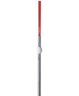
Applicable equipment
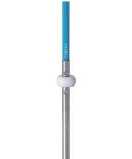
This tool is used on full cover type equipment with rotational speed control (> 6500 min-1).
Burr thickness ≤ 0.1 mm (Burrs this size can be easily bent by fingernails)
Burr thickness Burr height
Tool composition
Brush, collar and shank are sold separately. Assemble before use.
Machining center Lathe (with live tools)
Brushes
Dedicated machine
This is a custom-made item. Contact XEBEC technical support for details.
Brush size is approximate as the tip expands with rotation.
Precautions for use
The brush will break if:
• used beyond the maximum rotational speed
• used with a pneumatic rotary tool
• rotated outside of the bore (outside workpiece)
The brush may break when used with:
• off-center or angled crossholes
• t-shaped holes, when the secondary bore diameter is > 50 % of the main bore
• crossholes, when the secondary bore diameter is > 25 % of the main bore
Deburring, polishing on inner diameters, side walls, and outside diameter threads

Applicable equipment

Tool composition
This tool can be mounted on equipment shown below.
Machining center Lathe (with live tools) Dedicated machine Robot
Brushes
Shanks
Burr thickness ≤ 0.1 mm (Burrs this size can be easily bent by fingernails)
Burr thickness
Applicable burr size VIDEO
Brush and shank are sold separately. Assemble before use.
Brush main unit Shank
Automation of thread deburring
Output shaft

Material: SCM
Follows: Turning
Tool: W-A11-50
Before
A file was used to manually deburr the thread but failed to remove all burrs. Quality was unstable.
After
All burrs are removed and quality is stable.

Material: S50C
Follows: End milling
Tool: W-A11-50
As shown in the drawing at right, the best approach to removing burrs formed on surface A is to place the center of the brush at a 45-degree angle to the edge. Burrs are removed by rotating the brush both clockwise and counterclockwise.
Surface A
Before Burrs formed on the face were removed manually.
After Burrs are completely removed inside the machining center.
45deg.
Maximum parameters
MANUAL 16
Reduce the burden of adjusting for brush wear and achieve more consistent deburring and polishing results.


A built-in spring helps to maintain stable load, reducing the frequency of wear offsets and brush protrusion length

Floating holder in use

A built-in gear mechanism automatically adjusts brush protrusion length, reducing human error and providing consistent machining performance.

Self-adjusting sleeve in use
A tool for quick in-machine brush length adjustment.
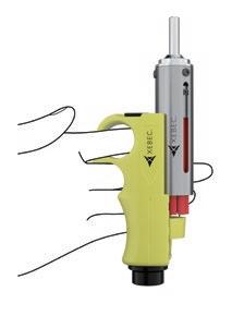
Straight Shank Type
BT Shank Type Patented
A built-in spring helps to maintain stable load, reducing the frequency of wear offsets and brush protrusion length adjustments.
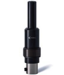


Applicable equipment [Straight Shank Type]
This holder can be used on equipment shown below.
Straight Shank Type used with XEBEC Brush Surface (φ6 – 100)
BT Shank Type used with XEBEC Brush Surface (φ6 – 25) VIDEO

Applicable equipment [BT Shank Type]
This holder can be used with machine tools that are compatible with BT30/40 shanks.
Machining center Lathe (with live tools)
t Installed when shipped.
Dedicated machine Robot
l Attachments included when shipped.
Optional φ3 bush is available.
Refer to p. 20 for the spring load.
φ6 bush sold separately.
Refer to p. 20 for the spring load.
Precautions for use
• Lower the tool vertically onto the workpiece.
• The tool cannot be used on surfaces that are discontinuous or have protrusions.
• The tool may not function correctly on a horizontal machining center when spring load is low.
This tool has a built-in spring. The spring is compressed when the brush contacts the workpiece surface.
Lower the brush to compress the built-in spring. The spring contracts up to 6 mm.

Built-in spring compressed
Product in use
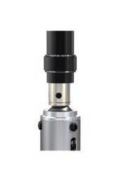
Built-in spring without load
The diagram to the left shows how to use the tool effectively.
1. Approach the workpiece surface from above without rotating the brush.
2. Set the depth of cut and compress the spring.
3. Rotate the brush and start feeding with the spring compressed.
4. Stop rotation and feed when finished machining.
5. Remove the brush upward from the workpiece surface.
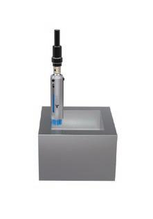

Avoid cavities and protrusions to ensure proper operation of the floating mechanism.
A built-in gear mechanism automatically adjusts brush protrusion length, reducing human error and providing consistent machining performance.

Applicable equipment
This tool is used on equipment capable of precise angular control of the sleeve.
Consists of a sleeve and rack gear. Brushes are sold separately.
Sleeve Rack gear
Machining center Dedicated machine Robot
Sleeves
Mount the rack gear inside the machine.
The brush protrusion length is adjusted by rotating the side gear built inside the sleeve with the rack gear.
Rack gear Side gear
The main body side gear and the rack gear are meshed.
Rack gear Rack
As shown above, the main body passes through the rack.
The brush protrusion length can be adjusted in increments of 0.05 mm. It is possible to make an adjustment of up to 1 mm in a single pass. This allows adjustments to be made at a predetermined interval corresponding to tool wear.
Compact tool holder whose length under the gauge line is 23.5 mm (including bush flange thickness 1.5 mm). Optimal when space is limited.
Only for use with XEBEC tools
Used with
XEBEC Brush Surface
XEBEC Self-Adjusting Sleeve
XEBEC Floating Holder
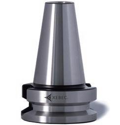
Applicable equipment
This tool can be used with machine tools that are compatible with BT30 shanks.
A tool for quick in-machine brush length adjustment. Product code Matching brush diameter
• Move the brush rest using the adjustment knob to set the amount of brush protrusion.
• Tighten the fixing nut.
• Hold the unit in one hand and align the sleeve rest with the sleeve end.
• Loosen the adjustment screw on the sleeve to allow the bristles to drop to the brush rest.
• Tighten the adjustment screw to secure the brush in place.
Used with
XEBEC Brush Surface (φ15 – 100)

Special deburring cutter and made-to-order tool path
“There must be a way to automate crosshole deburring!”
Our efforts to automate deburring made us aware of other problems requiring innovative solutions. We started developing a means to remove somewhat larger burrs from the edges of complex shaped workpieces, without scratching adjacent surfaces. The result was a product that combines optimal tool geometry for deburring with tool paths that inhibit burr formation. It was also symbolic of our approach to development— drawing from whatever field necessary to solve a problem.


A solution combining a made-to-order tool path program with a dedicated cutting tool for high quality finish, extended tool life and the world’s fastest automated deburring of drill holes. The ready-to-use CNC program is

XEBEC Deburring Tool Path
Made-to-order CNC tool path program

An optimized tool path and use of the ideal approach angle enables uniform break width on edges, while inhibiting formation of secondary burrs.
Before After
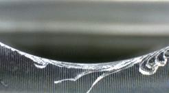
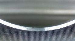
Five different tool paths provide a choice of edge break widths. (Refer to p. 29 for cutter diameters and corresponding edge break widths.)
Tool life is increased by continuous displacement of the cutter contact point.

Area of tool used (contact range)

Cycle time is reduced because there is no wasted motion in the cutter path. Cycle time is up 10 times faster than conventional deburring tools.
Material : SUS304
Planar
:
Applicable burr size
Burr thickness ≤ 0.2 mm (Burrs this size can be bent by fingernails)
Ideal for deburring both front and back of drilled holes. Burr thickness

Applicable equipment


This tool is used on equipment with 3-axis simultaneous control.

Consists of a spherical deburring cutter and made-to-order tool path. Refer to p. 29 - 30 for information on the made-to-order tool path (CNC machining program).
Machining center Lathe (with live tools)
Valve
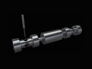
Material: Free cutting steel
Follows: Drilling
Tool: XC-18-A
Before
Deburring was done in 3 steps (φ2 zero cut, nylon brush deburring, φ3 zero cut), with a different tool for each. This resulted in a long cycle time.
After
Deburring is performed with a single cutter. Cycle time is 9 seconds shorter and tool cost is reduced.
Uncoated
Industrial robot part

Material: SUS304
Follows: Tapping
Tool: XC-18-A
Before
A lengthy manual deburring was followed by a tap zero cut and air blow. This resulted in a very long cycle time.
After
XEBEC deburring tool path reduces the deburring time from 120 to 40 seconds. The workplace is safer as manual deburring is no longer used.
Precautions for use
• XEBEC Back Burr Cutter is designed for CNC machines. Never use it as a hand tool.
• Turning on advanced preview control on the machine tool results in uniform edges.
• The machining error on holes must be kept as small as possible.
• Machining parameters will vary for the straight type when protrusion lengths other than 10D (shown in table) are used.
• Rotational speed and feed rates shown are intended as guides for setting starting parameters.
• In the event of abnormal vibration or noise, reduce the rotational speed and feed rate proportionally.
• If the maximum rotational speed and feed of the machine is below the starting parameters, reduce them both proportionally to the machine’s capability.
Patented
An integral component of this deburring solution, XEBEC Deburring Tool Path is a made-to-order CNC tool path program that ensures optimal performance of the XEBEC Back Burr Cutter.

Standard paths are readily available for the commonly encountered crosshole configurations shown below.

The same cutter can be used for many different types and sizes of hole. This reduces the number of tools in the ATC and the cycle time.
Deburring amount and allowable cumulative error
Deburring amount is the chamfer width after an edge is deburred.
Standard paths are available for thread sizes from M3 to M24.
Deburring amount
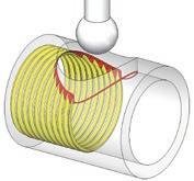
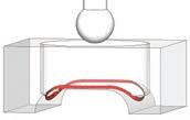
A customized tool path for extremely complex edge profiles.

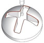
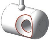


A made-to-order tool path for commonly encountered crosshole configurations.
STEP 1
Free assessment
You check whether the XEBEC Back Burr Cutter and Deburring Tool Path can be used with your workpiece and machine. The result is available immediately.
Online Application Form
STEP 2
Quotation
You receive a quotation by submitting your contact information.
All you need to do is to enter a few dimensions including hole diameters and to specify the orientation of the workpiece inside the machine.
Visit the special website below to conduct a self-assessment and submit a request for quotation.
https://xebec-backburr-cutter.com

STEP 3
Order
Send your order to the XEBEC distributor in your region after confirming the details.
Ordering XEBEC Deburring Tool Path All Edges
Please contact XEBEC directly to request XEBEC Deburring Tool Path All Edges, a customized solution for deburring paths which to do not belong to the six standard types shown on p. 29.
WEBSITE
Burrless chamfering with the world's first V-shaped blade
“Let’s make a chamfering tool that only XEBEC would think of.”
At the time, we were looking for additional ways to automate the deburring process and reduce the burden on users. The tools we offered could not provide an exact chamfer. In many cases, users had to alter break edge instructions on drawings to permit edge blending. After much consideration, we came up with the concept of a chamfering tool that does not produce secondary burrs. And settled on the world’s first V-shaped blades as the optimal choice for our tool.


The world’s first V-shaped blades (patented) chamfer without creating secondary burrs, eliminating the need for deburring after
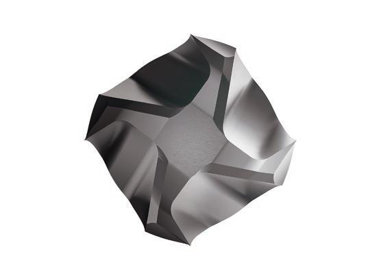
The multi-blade design enables high feed rates for reduced machining time.







This cutter has twice the tool life of conventional chamfering tools.
XEBEC Burrless Chamfering Cutter Straight blade
Material: SUS304
Flat tool tip prevents rounding and chipping of the tool tip, reducing tool length measurement errors and improving machining positional

Burrless chamfering with world's first V-shaped blade


Applicable equipment
This tool can be mounted on equipment shown below.
Uncoated N: Non-ferrous metal O: Resin
Automation of chamfering
Cooling water pipe block

Material: SUS304
Follows: Drilling
Tool: XC-C-06-M
Before
Burrs were formed when chamfering. Manual deburring was required.
After
Shortened the chamfering time. Manual deburring is no longer required after chamfering.

Material: S50C
Follows: End milling
Tool: XC-C-06-M
Position the chamfering alignment diameter at the chamfering center point of the workpiece. Chamfer
Before
Oil stone was used to remove burrs after chamfering. However, it scarred the surface.
After
Oil stone is no longer needed and quality is improved.
Machining parameters
Offsets
Starting parameters


“A friend with a dream worth realizing.”
XEBEC was founded from a belief in the invention of a childhood friend. A grindstone that can be molded, but does not bend, break, or chip. With the vision of the world’s best ceramic grindstone firmly in their minds, two friends teamed up with a materials manufacturer and developed a unique ceramic fiber suited to grinding. They also received a patent for a grindstone with an original structure that maximizes strength and polishing performance. Known as XEBEC Ceramic Stone, this product now dominates the market for the polishing of intricate features in molds, such as ribs, bosses and corners, and has a reputation for making manual deburring safer and more efficient.
Patented
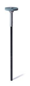
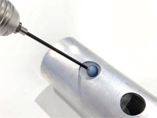
Deburring and polishing front and back of crossholes, grooves and areas deep inside the workpiece. The spring steel shaft absorbs vibrations for a soft surface contact.

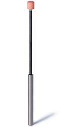

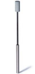
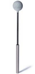
Applicable equipment
This tool is used on equipment with rotational speed control.
Machining center Lathe (with live tools) Dedicated machine Robot Rotary tool (electric) Ball
Cylinder type
Applicable burr size
Burr thickness ≤ 0.2 mm (Burrs this size can be bent by fingernails)
Burr thickness Burr height
VIDEO
Fig. 20 Fig. 22
Fig. 21
Fig. 23 Fig. 24
Disc type - stone
Deburring crosshole
Aircraft pipe part
Shaft
Before

Material: Stainless steel
Follows: Drilling
Tool: CH-PM-6B
Deburring was carried out with a rubber grinding stone on a rotary tool. Finish quality varied depending on the workers’ skill. 40 minutes was required to deburr 16 crossholes.
After
The tool is inserted in a crosshole and retracted gently while tracing around the hole edge. Quality of finish is uniform and less time is required for deburring.
Before

Material: SCM
Follows: Drilling
Tool: CH-PM-145D
An oil-impregnated grinding disc was used. The grinding stone shaft was short, making it difficult to access the deburring area. Tool life was poor.
After
The longer shaft of the disc type grinding stone makes it easy to access the groove. The ceramic fiber stone is replaced less often because it has a longer tool life. The shaft is reusable. Only the grinding stone is replaced.
The entire surface of the ceramic stone is abrasive and therefore can be used for deburring and polishing.
Ball type
Characteristics
Cylinder type

The spring steel shaft absorbs vibrations for soft contact with the workpiece surface. The ceramic stone does not bounce around, thereby reducing the risk of scratching the workpiece. This makes this tool ideal for polishing and deburring areas that are deep inside the workpiece. The stone is safe to touch as it is not a cutting tool.
Disc type

Trial set
This set includes a disc type stone and shaft.
Product code
CHPM14D-SET
φ2.3 to φ3 Collet Adapter
Adapts the φ2.3 shaft to fit on rotary tools with φ3 shanks.
Product code RMP3024X
Precautions for use
A ceramic stone tool will be damaged when:
• used beyond the maximum rotation speed
• used with a pneumatic rotary tool
Users of the disc type should be careful to use only normal (clockwise) rotation. Reverse (counter-clockwise) rotation may cause the screw to loosen and the head to fly off.
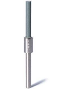
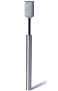
Suitable for use with pneumatic rotary tools at high rotational speed
Applicable equipment
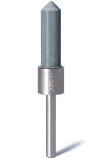
This tool can be mounted on rotary tools. Rotary tool
Rotary tool
Burr thickness ≤ 0.2 mm (Burrs this size can be bent by fingernails)
Burr thickness
Applicable burr size VIDEO

Material: Stainless steel
Tool: AX-PM-6T
Before
A file was used for deburring. However, it caused secondary burrs and a quality problem.
After
Secondary burrs are not formed and edge quality is improved.
Before

Material: Aluminum
Tool: AX-PM-6T
A rotary bar was used because the burrs were large. However, there was a safety problem.
After
The switch to abrasive stone makes the process safer to perform. The ceramic fiber stone’s grinding power improves work efficiency.
All surfaces of the ceramic stone are abrasive and all of them can be used for deburring and polishing. These ceramic stones are capable of withstanding high speed. As such they can be used with pneumatic rotary tools in addition to electric rotary tools.


Battery-powered rotary tool for use at workstations where power supply is unavailable. The handpiece is ultra-lightweight, ideal for manual operation without causing fatigue.

Capable of about 5 hours of continuous use on a single charge.
Handpiece with stand, controller, ON/OFF foot switch, power cable for charging
Refer to the charts below and select the brush color based on the workpiece material, burr thickness and surface roughness.
Deburring
Resin Copper, Brass Aluminum Steel
Workpiece material
Not all brush colors are available in all sizes.
HRSA (heat resistant super alloy)
Stainless steel HRSA steel Cast iron
Hard material
Copper, Brass Aluminum Steel
Workpiece material
Not all brush colors are available in all sizes. HRSA (heat resistant super alloy)
Take the following actions, if burrs remain despite using the recommended depth of cut for the given burr size.
Increase the rotational speed to the maximum.
2. Check the rotational direction of the brush XEBEC recommends cutting upwards so that the bristles lift burrs up.
3. Change the brush color
Check whether the brush color is suitable for the workpiece material and burr size. The grinding power of colors increases as follows: pink < red < white < blue.
Stainless steel HRSA steel Cast iron
Hard material
It is not possible to remove burrs with brushes without rounding edges to some extent. Take the following actions to improve edge sharpness.
1. Increase feed rate
To make a sharper edge, increase the feed rate in 1,000 mm/min increments within the range where burrs can be removed. Increasing the feed rate also helps reduce the cycle time.
2. Decrease rotational speed
Decrease rotational speed in 10 to 20 percent increments within the range where burrs can be removed.
3. Check the brush color
Check whether the brush color is suitable for the workpiece material and burr size. Rounding of edges increases as follows: pink < red < white < blue.
Reference data - Tool life
Example 1 Example 2
Material Aluminum die-casting
Follows Face milling
Burr thickness 0.1 mm
Tool path length 1000 mm/piece
Tool A11-CB25M
Rotational speed 4000 min-1
Feed rate 2400 mm/min
Depth of cut 1 mm
Wear amount 50 mm out of 75 mm
Tool life 10 km (10000 pieces)
Material S45C
Follows End milling
Burr thickness 0.1 mm
Tool path length 200 mm/piece
Tool A21-CB25M
Rotational speed 4000 min-1
Feed rate 2000 mm/min
Depth of cut 0.5 mm
Wear amount 50 mm out of 75 mm
Tool life 3 km (15000 pieces)
Tool life varies greatly depending on the material, machining conditions, and burr size and direction.
The above data is not guaranteed. Please use as a guide.
It may be possible to improve the surface finish. Try the following.
1. Check the brush color
The ability to improve surface roughness is inversely proportional to the grinding power, meaning that A13 (pink) achieves the best surface roughness, followed by A11 (red), A21 (white), and A32 (blue). Make sure to select the appropriate brush color based on the workpiece material and target surface roughness.
2. Wet machining
The brush can be used for both dry and wet (oil-based and water-soluble) machining. Wet machining may improve surface roughness and tool life.
3. Increase the number of passes
When comparing with the same cycle time, increasing the number of passes makes a bigger difference than decreasing the feed rate.
Reference data - Surface roughness after deburring
Refer to the chart below and select the brush color based on the workpiece material, burr thickness and surface roughness.
Resin Copper, Brass Aluminum
Steel
Workpiece material
Stainless steel
HRSA steel
Cast iron Hard material Burr
HRSA (heat resistant super alloy)
Refer to the chart below and select the brush color based on the workpiece material, burr thickness and surface roughness.
Resin Steel
Copper, Brass Stainless steel
Workpiece material
Burr size
Achievable surface roughness
Brush (color)
Aluminum
HRSA steel
Cast iron
Hard material
Micro fine burrs
Burr thickness (≤ 0.1mm)
≤ Ra 0.1 μm
≥ Ra 0.1 μm
A12 (red) A33 (blue)
A34 (dark blue)
Grinding power High
HRSA (heat resistant super alloy)
Take the following actions, if burrs remain despite using the correct brush and rotational speed for the given burr size.
1. Check the brush color
2. Increase rotational speed to the maximum
3. Increase the number of passes
4. Decrease the feed rate
Try the following, if tool life is short despite using the correct brush for the given burr size.
1. Decrease the rotational speed
2. Increase the feed rate Material S45C
Example
Follows
Burr
Main
Crosshole
Tool CH-A12-5M-TL
Rotational speed 10000 min-1
Feed rate 300 mm/min
Depth of cut 1 mm
Wear amount 10 mm out of 50 mm
Tool life 4500 holes
Tool life varies greatly depending on the material, machining conditions, and burr size and direction. The above data is not guaranteed. Please use as a guide.
Take the following actions, if burrs remain despite using the recommended depth of cut for the given burr size.
Increase the feed amount in increments of 10 to 20 percent.
Try the following, if tool life is short despite using the correct brush for the given burr size.
Increase the feed rate in increments of 10 to 20 percent.
It is not possible to remove burrs with brushes without rounding edges to some extent. Take the following actions to improve edge sharpness.
Example
Material S45C
Follows End milling
Burr thickness 0.1 mm
Tool path length 120 mm/piece
Tool W-A11-50
Cutting speed (Rotational speed) 250 m/min (1600 min-1)
Feed per bundle (Feed rate) 0.7 mm/bundle (7000 mm/min)
Depth of cut 0.2 mm
Wear amount 50 mm out of 75 mm
Tool life 600 m (5000 pieces)
Tool life varies greatly depending on the material, machining conditions, and burr size and direction. The above data is not guaranteed. Please use as a guide.
Schedule a regular maintenance for cleaning and greasing sliding parts to ensure smooth movement and functioning. Recommended grease: Lithium soap grease (NLGI Grade #2).
Please make sure to read the instruction manual before use.
In order to ensure safety, be sure to observe the operator safety measures and operational precautions listed below.
The following precautions exist to ensure safe use of the products and prevent injury to persons using the products and other persons in the vicinity, as well as prevent property damage. They are classified as “Warnings” and “Cautions” depending on the level of potential injury and danger involved. “Warnings” and “Cautions” should be strictly observed as they all are related to safety.
[WARNINGS]
These have the potential to cause death or serious injury to persons or serious property damage if handled improperly.
[CAUTIONS]
These have the potential to cause injury to persons or property damage if handled improperly.
[Use
Wear safety glasses, protective gloves and masks when using the tools. Wear clothing with long sleeves or other clothing that does not expose the skin. Cuffs and hems of clothing should be tightly fastened.
Machine tools and dedicated machines should be equipped with covers and other safety measures capable of protecting users from injury in the event of tool fragmentation.
Cutting dust and burrs are scattered into the air with the rotation of the tool. These should be removed by a dust collector and persons should not enter the affected area.
An enclosure should be installed around the work area to prevent persons other than the operator from entering the work area. Persons who enter the work area should always wear protective clothing and use protective equipment.
Ignoring the aforementioned warnings may result in the following:
• Fragments and cutting particles may enter the eyes, causing loss of sight in severe cases.
• Fragments and cutting particles may cause injury by cutting into skin.
• Cutting dust resulting from tool use may irritate the skin, cause allergic reactions and damage lungs.
Operate the tool for at least one minute (3 minutes after the tool has been replaced) before conducting any actual cutting. Cease operation immediately in the event of any sign of abnormality with the machine or loosening of the tool shank. Continued use may result in the shank flying out of the holder, causing damage to the machine, the jig, and workpiece, as well as injury or loss of sight to the operator.
Cease operation immediately at the first sign of abnormalities such as vibration. Continued use may result in the shank flying out of the holder, causing damage to the machine, the jig, and workpiece, as well as injury or loss of sight to the operator.
Do not operate the tool beyond its maximum rotational speed. Set the machining conditions based on the instruction manual. Operation at speeds beyond the maximum rotational speed may damage the tool, the machine, the workpiece, and also cause loss of sight or other injury to the operator.
• A dust collector should be used during machining and cleaned thoroughly afterwards.
• Insufficientremovalofdustandcleaningofdustcollectorsmayresultindamagetomachinetool slides and other exposed sliding surfaces.
XEBEC has been helping factories and machining shops around the world automate their deburring processes since 2002. With our wealth of knowledge accumulated over the years, we strive everyday to solve customer deburring problems faster than before. We aim to change the way people think about deburring and create valueadded in customers’ finishing processes. A world where people can make use of their creative talents to the fullest, is a world where XEBEC wants to be.
Ongoing technological innovation through integration of materials, hardware and software from many scientific fields enables us to find superior solutions to fundamental problems.
Challenging accepted practices to optimize and innovate business processes such as product marketing, manufacturing, sales and delivery.
Attaching the upmost importance to every aspect of quality management, such as stable product quality, shipping accuracy, and timely and polite customer support.
XEBEC Burrless Chamfering Cutter™ released. Jul. 2023
XEBEC Stone™ Flexible Shaft Disc Type released. Feb. 2022
XEBEC Brush™ Crosshole Extra-Large released. Sep. 2021
Nov. 2018 Corporate branding renewed.
Jun. 2018
XEBEC Back Burr Cutter and Deburring Tool Path chosen product of the year in Germany's Best of Industry Awards (cutting division).
Mar. 2017 'Deburring Productivity Day' certified by Japan Anniversary Association
XEBEC Brush™ Wheel Type released. Oct. 2016
XEBEC Back Burr Cutter and Deburring Tool Path™ released. Jun. 2016
Nov. 2015 'XEBEC Plus Engineering Center' opened in Okazaki, Aichi.
XEBEC Self-Adjusting Sleeve™ released. Oct. 2015
Mobile Micromotor System released. Apr. 2015
Mar. 2015 One of 100 companies awarded the Diversity Management Award by the Ministry of Economy, Trade and Industry.
May 2014 Headquarters moved to current location at Kojimachi, Chiyoda-ku, Tokyo.
Jun. 2013 'XEBEC Plus R&D Center' opened in Ota-ku, Tokyo. Vertical machining center (with additional axis) acquired.
XEBEC Brush Length Adjustment Tool™ released. Apr. 2013
Aug. 2012
XEBEC Floating Holder™ released. Oct. 2010
XEBEC Stone™ Mounted Point released. Oct. 2008
Test cut facility established at the head office. SCARA robot acquired.
Oct. 2007 Norihiko Sumiyoshi appointed president and CEO.
XEBEC Stone™ Flexible Shaft released. XEBEC Brush™ Crosshole released. Nov. 2004
XEBEC Brush™ Surface released. Apr. 2002
XEBEC Ceramic Stone™ Meister Finish released. May 1998
Jun. 1997
Certified as an authorized corporation by the Ministry of Economy, Trade and Industry under the Act on Temporary Measures for Facilitating Specific New Businesses.
Jun. 1996 XEBEC Technology Co., Ltd incorporated. (Founder: Takehiko Sumiyoshi)
Fuerte Kojimachi 1-7 Building 4F, 1-7-25 Kojimachi
Chiyoda-ku, Tokyo, 102-0083, Japan
Tel. +81-3-3239-3481 Fax. +81-3-5211-8964 www.xebec-tech.com
customerservice@xebec-tech.co.jp
