6 minute read
Metrology 101: Verifying the Integrity of S-Parameter Measurements


Christopher L. Grachanen National Instruments if used, to within acceptable limits. For transmission
Advertisement
S-Parameters
Vector Network Analyzers (VNA) are used to measure a variety of RF parameters such as transmission loss, reflection loss, phase and group delay for a variety of passive RF devices and signal interconnections. RF devices span from attenuators and terminations to power splitters and directional couplers. Interconnections include RF cables, adapters, fixtures, probes as well as PCB signal traces. These RF devices and interconnections as measured by VNAs yields s-parameters. S-parameters describe the response of a RF device or interconnection to a stimulus (incident signal) applied to any or all of its connections (ports). S-parameters are essentially ratios comparing port stimuli to port responses to the applied stimuli.
VNAs are configured with one or more ports depending on its intended purpose i.e. making singleend measurements (one or two ports), making differential measurements (four ports) and making multiple aggressor/ victim crosstalk measurements (greater than four ports). S-parameter naming nomenclature is port based denoting stimuli port and response port. For a two-port s-parameter, the naming nomenclature starts with an ‘S’ followed by the response port and then stimuli port: S11 = Stimuli on Port 1, Response on Port 1 (Reflection) S12 = Stimuli on Port 2, Response on Port 1 (Transmission) S21 = Stimuli on Port 1, Response on Port 2 (Transmission) S22 = Stimuli on Port 2, Response on Port 2 (Reflection)
VNA Calibration
Prior to making s-parameter measurements, the VNA should be within its calibration interval if measurements need to be traceable, a prerequisite for accredited based measurements, and allowed sufficient warmup time.
VNA calibrations are typically performed annually and should not be confused with VNA S-parameter Vector Cal (SVC) performed prior to making s-parameter measurements which are also often referred to as components from within the VNA measurement ensemble i.e. VNA, cables and adapters and fixtures
VNA calibrations. VNA SVC is used to remove error measurements these errors components are associated with measurement port isolation, load matching and the frequency response of transmission tracking. For reflection measurements, these error components are associated with measurement port directivity, source matching and the frequency response of reflection tracking.
VNA SVC is performed using RF standards with known characteristics and/or known relationships. These standards are characteristically grouped together into a kit commonly referred to as a ‘VNA Cal Kit’ depending on the type of VNA SVC being performed. One of the most popular VNA SVC types is called SOLT (ShortOpen-Load-Thru). A SOLT VNA Cal Kit with have RF standards with characteristics of a shorted transmission line, an open transmission line, a termination (typically 50 ohms) as well as an adapter (thru) for connecting measurement ports together (not needed for a single port SVC). Another popular VNA SVC type is the LRL (Line
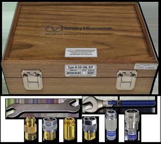
Maury Microwave Type N, VNA Calibration Kit, model 8850CK40. Photo courtesy of Maury Microwave.
Reflect-Line), also called TRL (Thru-Reflect-Line). VNA Cal Kits are made with different RF connectors to support specific frequency ranges such a N-Type (typically DC to 18GHz) and APC 3.5mm (typically DC to 26.5GHz). VNA Cal Kits usually include a calibrated torque wrench to insure proper torqueing of coaxial connections.
S-parameter measurements may be further enhanced after performing VNA SVC using techniques to reduce measurement uncertainties associated with VNA drift and cable flex. Additionally, de-embedding techniques may be used to reduce the effects of adapters, fixtures and probes which are required to connect to an RF device or interconnection.
Tests For S-Parameter Measurement Integrity
After performing VNA SVC and employing the aforementioned measurement enhancement techniques as applicable one could reasonably presume that derived s-parameter measurements are accurate and correct. But what if the VNA SVC and/or enhancement technique was performed in error and/or a VNA Cal Kit standards used to perform SVC was out of specification due to its coaxial connector being worn or damaged? What if during the course of performing a VNA SVC one of the cable connections becomes loose or intermittent due to cable flexing? An easy way to flag possible VNA SVC problems is to measure a check standard and compare its s-parameter values to previous measurements. A check standard such as an attenuator does not need to be accurate but should possess stable attributes over time in order to assess measurement repeatability. It must be noted that using a check standard gives insight into measurement repeatability but will not identify a systematic error common to all measurements. Again, after measuring a check standard and determining good repeatability one could reasonably presume derived s-parameter measurements are both accurate and correct. But what if the physical connection to one of the ports of a RF device or interconnection under test is less than optimal and/or a cable becomes loose due to flexing prior to or during the measurement? The following are tests that can be performed on captured s-parameter measurements from passive RF devices and interconnections to ensure measurement integrity:
Passivity – A passive device such as an attenuator does not generate energy such that there should be no gain or amplification i.e. no amplitudes greater than the applied stimuli such that transmission s-parameter need to be ≤ 1.
Reciprocity – The losses and delays are the same between any pair of ports regardless of direction of stimuli propagation. For a two port VNA ensemble S12 losses and delays equals S21 losses and delays.
Causality – A passive system only produces a response after it has received a stimulus and not before i.e. an output must occur after an input and not prior to that input being applied. The frequency spacing of the s-parameter data as well as the maximum frequency of the s-parameter data can affect the apparent causality of the measurement data. One must be sure that there are sufficient frequency points across a span. The ability to determine if a calibrated VNA meets causality requirements can be impaired if the frequency spacing between measurement points is too large.
Some signal integrity-based software programs have the means for assessing s-parameter passivity, reciprocity and causality as well as providing the means for enforcing compliance. Additionally, MatLab scripts can be created to perform these tests on captured s-parameters. A 2012 DesignCon white paper titled, “Fast and Optimal Algorithms for Enforcing Reciprocity, Passivity and Causality in S-parameters” 1 is a good starting point for understanding testing algorithms. An excerpt from this paper describes its content:
These errors in S-parameters may manifest themselves as violation of certain physical laws. Besides leading to incorrect conclusions, such violations present significant difficulties while using such S-parameters in system simulations like generating and analyzing eye patterns, or equalization of the modeled channels etc. This paper focuses on rectifying the violation of three such properties of S-parameters – causality, passivity and reciprocity.
Conclusion
Despite all s-parameter measurement preparations i.e. VNA annual calibration, VNA sufficient warmup time, VNA SVC, measurement uncertainty enhancements, de-embedding and check standard repeatability, derived s-parameter measurement can be seriously flawed due to passivity and reciprocity non-compliance and/or excessive causality influence. Best practice for ensuring the integrity of s-parameter measurements is to run tests for assessing passivity, reciprocity and causality. It should be noted that s-parameters may be transformed from the frequency domain into the time domain providing additional insight into s-parameter integrity not addressed in this paper.
Christopher L. Grachanen (chris.grachanen@ni.com), Principal Program Manager Global Calibration Capability, National Instruments, Austin, TX 78759.

