 Cameron Mixner
Architectural Portfolio
Table of Contents


 Cameron Mixner
Architectural Portfolio

Interpolating renders created by Midjourney, the monastery was to be made out of spheres. Initially, the maximal approach was taken, but soon after was slimmed down to a few spheroid shapes. The monastery is located on the second floor of this structure. It is initially carved out from two large orbs, then three eggs were used to carve out more of the space as well as seating. Then attached to those eggs are barnacles that are attached like how they would be to a rock at the site, and are used as carved out areas to capture and diffuse light to be used in the space itself. There are also three areas inside that have porous openings to allow light in and views to the exterior. To be able to enter this space, you must use the spiral staircase. The ground floor is made of egg shapes to make out the ten individual units, one of which is the spiral staircase. The habitable units are then carved out further and used for personal storage, a bathroom, and shower room, with a bed making up most of the floorspace. There is a central pathway that is directed by the landscape along the curve of the building. Light is let through from angled cuts along the outside walls. Not allowing for views inside the units to be visible for seclusion. Along the front exterior is a wall replicating the same outline of the monastery, with porous opening similar to the openings upstairs, allowing for some privacy, but also still allowing for views along the water.


 AI Generated Image Post-Design
AI Generated Image Pre-Design
AI Generated Image Pre-Design
AI Generated Image during Design

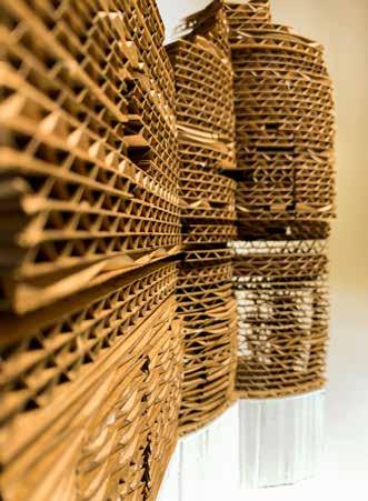


 Photo of Physical Model
Render of Entrance Stairway
Render of Sanctuary Units
Render of Exterior View
Photo of Physical Model
Photo of Physical Model
Render of Entrance Stairway
Render of Sanctuary Units
Render of Exterior View

The intentions of this community center are to bridge the disconnect between site conditions on the northern and southern sides. On the south we have more com pact, old residential settlement consisting of mostly three-family triple-decker houses and apartments. The north side consists of more mixed-use and commercial buildings with two high-rise apartment buildings. Our design creates an underpass-like pedestri an walkway that connects these two conditions. This community center is welcoming to residents of all living situations.

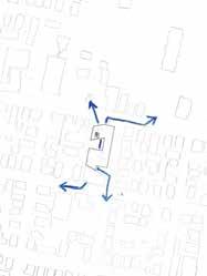

The population that seems to be the most in need of this space is poor youth. This population will be served through the child care program and the sports hall. The spatial situations visually connect the various levels interiorly and exteriorly. We are using local recycled granite to harken back to the origins of the city of Fall River being a textile mill town. The underpass walkway has the ability to become a very lively and welcoming through the incorporation of outdoor furniture and the capacity to invite performances and even vendors. The intent is to make this a safe space for youth and adults to congregate and interact with their community.

The main areas of the building, like the theater and the sports hall are dou ble-height spaces. These spaces are not independent spaces from the building but they interact with the other floors visually and directly through the use of balconies and cantilevered pathways through and between. The walkway through the building is visually connected with the interiors of the building using glass curtain walls.
The building will be constructed using CLT for the entire structure, with it being mainly consisting of Post & Beam, with some Load Bearing walls used in a few of our spaces. The building has enough open space that it can evolve and adapt to whatever it may become and need. The ground floor mainly consists of glass to make the building light and transparent, allowing people to walk through the underpasses and get a glimpse of the many activities involved throughout. The upper floors are more closed off to allow for privacy in meeting spaces as well as in the classrooms.


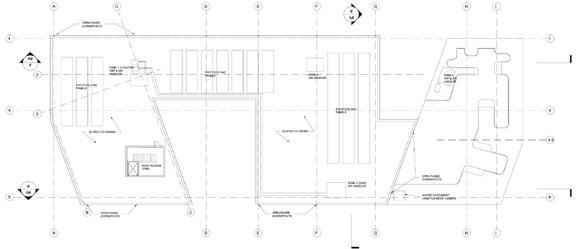


1 - Solar panels collecting energy from the sun to offset the buildings energy usage.


2 - There is sun shading which helps block the harsh summer sun from entering the building, while allowing the winter sun in to heat the building naturally.


3 - Natural ventilation is used to help cool the building in the warmer months and reduce active system use. Vents are located on the vertical ends of the windows to allow fresh air to pass through as desired.
4 - Water that is collected from the roof is brought to the outer edges of the building, and distributed throughout.


5 - The interior courtyard facades have water catchers that move the water to the edges of the building to be distributed throughout.

6 - There are pipes underneath the back side of the building where water is brought to water the plants.
7 - Water pipes are underneath the green areas on the rooftop to distribute the water and water the plants.

8 - Water is pushed through the solar panels to cool them which boosts their efficiency to gain more power.
A snippet of the full 255 page booklet that was created with this project.

Roof construction
Parapet system
2” rigid insulation
CLT Lintel
Window System

Opening Mechanism for panels behind windows
Aluminum & Glass Panels
Wall ties per glass panel
CLT Floor system
color
Glazing system
Ground floor construction
½” Porcelain tile
4” Conc. slab
2” rigid insulation 6” gravel
Conc. Footing
2” rigid insulation
Footing drain
Ceramic coated aluminum panel with Tinted glass


 1:40 Model Photos
Portion of Physical Structural Model


 Physical Facade Analysis
Physical Building Section Analysis


the stage at the middle of the structure. The shape of the Shell was generated with acoustics in mind, while also providing shelter to the people sitting in the permanent seating area. The extended seating portion is more gradual and not fully covered. The Shell is held together using a steel framing system generated in Grasshopper. The inner deflector is made out of timber paneling, with areas for lights to be hung as well as speakers. It is hung up using steel cables. Once inside the structure, you see the stage as well as the water, as the trees have been removed to have an uninhibited view of the bay.
The Shell is a music pavilion located on the Global Heritage Hall lawn. It is positioned in the path of GHH as you walk out to the lawn. The natural down slope was formed to create the seating, with the stage at the middle of the structure. The shape of the Shell was generated with acoustics in mind, while also providing shelter to the people sitting in the permanent seating area. The extended seating portion is more gradual and not fully covered. The Shell is held together using a steel framing system generated in Grasshopper. The inner deflector is made out of timber paneling, with areas for lights to be hung as well as speakers. It is hung up using steel cables. Once inside the structure, you see the stage as well as the water, as the trees have been removed to have an uninhibited view of the bay.


Axonometric Drawing
Overall Site Section Section of Shell Pavilion


The Dream Theater is a music hall located on the east facing peninsula. I wanted to make it and experience and landmark that has experiences throughout the building as well as the surrounding ground. The building floats off the ground and hovers over the water in the north, east and south directions. Hovering over and almost encapsulating the building is an anodized stainless steel facade that is a rich copper color. The color was chosen to be in contrast of the harbor. The shape went through many iterations starting conservatively, and eventually evolving to almost encapsulating the entire structure while still keeping the east and west facades relatively intact. There are moments where the facade is held back to allow for a balcony space on the northern point, as well as a cut through also along the northern end to allow for a lightwell to light up the two floors at that point. The site was reformed to include a renovated dock area, as well as experiences under the building and facade. The ground slopes up to the first floor of the building which opens to the lobby space that can lead you to the theater space. As you enter into the theater space, it opens up to a direct view to the water and Greater Newport. You also get hints of the facade almost starts to encroach on the view. The plans were originally boxes, but I then wanted to take away the corners, in the secondary spaces as well as the main theater space.
Sketches of Various Elements used for Overall Design


N/S Overall Section

Initial to Final Models of the Building Shell
Initial Models of the Overall Building Form
Sound Diagram in Section
Sound
Second Floorplan


Exploded Axon of Shell with Structure
E/W Overall Section


 Render of Theater Space looking at Stage


 Render of Balcony Space on Second Floor
Providence Food Market & Station takes the existing structure and transforms it into a brand new food market unlike anything in Providence currently. The new market provides an additional two floors with added shopping spaces. Along the front of the building are angled facades so depending on what direction you come towards the building, you either get a continuation of the old elements or the new glass elements connected to the new station. Alongside the new food market is a grand atrium that acts as a new pathway through the building, connecting the many icons of Providence together. Through the attrium we can enter into the new station. There are four openings to below to view the trains as well as the platforms being extended. There are now twelve ways to get to the platform allowing for a whole new influx of people to enter the city. The second and third floors provide security and extra seating.


 Diagram showing Expansion of Space


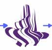


Amenista is the newest experience in Barcelona. During the day, it is an exhibition and event space, and at night it transforms into a nightclub. The way this happens is with origami-inspired elements throughout the site. The exterior elements are these moving cubes with triangular panels that fold and become fencing at night. The interior elements are moveable walls that can be tucked away under the stage at night. Both of these elements move on a grid track allowing for various layouts that can adapt to any event. The building’s program provides different spaces. The ground floor is an exhibition and event space with a stage, a set of bathrooms as well as a bar, and at the entrance of the club, there is a coatroom. The first and second floors are balconies that face on opposite sides of each other with bars and seating. Going up, there is a large rooftop bar with a kitchen. The basement is used as storage and archive space.


Exploded Axon showing main building concepts
Origami Transformation Diagrams showing movement and foldability


The purpose of this project was to design a courtyard that had seating as well as shading elements. Trees are natural shading, so that became the inspiration for the design. Balsa wood is very maliable when wet, so using different sizes to represent the various tree branch sizes to make the tree element look as natural as possible was necessary. I then started to randomly just place them in to create a space with efficient shading but also a beautiful space to be in. The flooring was inspired by the Japanese tatami floor mat proportions. The flooring stepped up and down throughout to create various paths. For seating and tables, some of the branches wrapped upon themselves to create custom seating for the space. The views below show the different light effects on the space at various times of the year and day.


These were working drawings created in my Construction Materials class, with proper notes as well as hatching and dimensions. These specific drawings are both from brick construction.
This series of photographs were taken in RI on a bike path at night to show the movement of light through the paths. The photos were then edited and distiorted in Photoshop to alter the normal experience of this journey.


I was lucky enough to study abroad from Jan. ‘20 to Mar. ‘20. In that time, I was able to live in Barcelona, and visit Toledo, Valencia, Venice & Paris to name a few. The trip was cut short due to coronavirus, but the experience was once in a lifetime. All photos were edited in Lightroom.


Photography has only been a passion of mine. I have selected some of my favorite photos I have taken in the past three years in various different places, including Bear Run, PA, Kennet Square, PA, Providence, RI, and Bristol, RI. All photos were edited in Lightroom.


