
PORT FOLIO Arch. Carla Altamirano Saavedra2021TO2018MILANODIPOLITECNICO-INTERIORS-ENVIRONMENTBUILT-ARCHITECTUREMSC.
ELEVATION WEST Scale 1:500 07 08 09 pág. 4 Design Studio 1st Semester (December 2018) Student Residence pág. 16 Construction Studio 2nd Semester (July 2019) Aquatic Center pág. 26 Interior Design Studio 2nd Semester (July 2019) Medical Center Beautiful Corner Elemental Heritage Rehabilitation Índice


10 11 12 pág. 40 Thematic Studio 3rd Semester (December 2019) Sustainable Regeneration pág. 58 Final Thesis Studio 4th Semester (July 2020) Motorway Service Area Reactivation pág. 70 Master Degree Thesis (September 2021) Motorway Service Area Reactivation Into the Green Landscape Interconnection Rest and Walk


4
Beautiful Corner
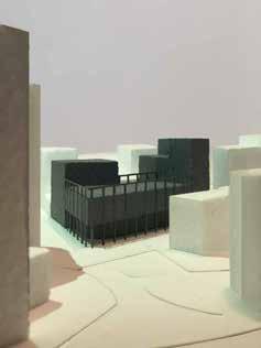
Located between the old and new Mi lan, the project takes the cultural po sition of respecting the heritage archi tecture of the site. The development of the project was mainly focused on the design of the corner and managing its acute angle. For this reason, the buil ding develops a continuous portico on both facades intersecting the corner. The design of the facade answers to main framework, double laered, whe re the main grid responds to the urban scale arounf the project, meanwhile a smaller grid answers to the interior scale of the student residence.
07
An opac pigment is mixed with the concrete of the building so its charac ter responds to a refresching atmos phere realted to the young users of the
Theproject.building is located in a very inte resting urban context, as it is where ancient and contemporary Milan meet. Therefore the building was designed mainly for its urban image rather than for its functional program. Since in a city like Milan, the function will be able to change according to the needs. That said, the character of the building res ponds to the classic regularity of an cient Milan and in turn the simplicity and geometry of modern Milan.
5

6 CORNERS Architectural Design Studio - WS 2018 - Politecnico di Milano Giancarlo Floridi, Angelo Lunati, Zachary Mark Jones - with Marta Bertani, Stefano Casula, Dalmasso, Emilio Ellena, Gianmario Pandozzi, Stefano Passamonti Altamirano, Ayda Khayyami Reference - Casa Economica Ground Floor. Building character model. Rome, Italy
ViadellaLegaLombarda
Redraw by the author Made by the author SofiaCORNERSProf.Carla

0 8 16 24 40m Facades. Redraw
From the corner towards the back of the building, the floors grow upwards, generating a terraced building. But above all, avoiding the sharp angle of the corner to protrude strongly and instead, the building manages to be that element that allows a smooth dia logue between the scales of the two floor residential houses and the ten floor buildings. A B D A C E B D EC
As a reference for the project, Casa Economica, located on Via della Lega Lombarda street in Rome was taken. A residential building within a triangular lot, where the sharpest corner is the corner for the city. The building is totally symmetrical. However, the access does not follow the symmetry, being located on only one side of the building, thus respon ding to functionality, rather than a mere architectural whim.
7 Elevation development - scale 1:500 Casa Economica by Innocenzo Sabbatini
CORNERS Architectural Design Studio - WS 2018 - Politecnico di Milano Prof. Giancarlo Floridi, Angelo Lunati, Zachary Mark Jones - with Marta Bertani, Stefano Casula, Sofia Dalmasso, Emilio Ellena, Gianmario Pandozzi, Stefano Passamonti Carla Altamirano, Ayda Khayyami by the author
8 0 20 40 60 100m Student Residence Ground Floor Building character model
9 0 10 20 30 50m Facades A A F B E C D C B E D F
0 20 40 60 100m Student Residence Roof Plan

11 0 5 10 15 25m NorthSouthWestFacadeFacadeFacade
0 10 20 30 50m Ground Floor Type Floor Second Floor Sixth Floor Student Residence


13 0 3 6 9 15m Section A - A´

14 Galery interior space model Foyer interior space model Student Residence


15 0 1 2 3 5m Facade Detail


VIEW OF THE POOL 0 30 60 90 150m


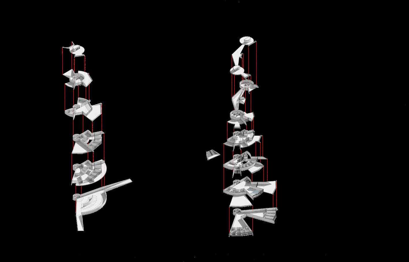
BUILDING CONNECTIONS Internal and external passages
17
Facades Diagram
BUILDING RELATIONSHIPS Stepping down in height and complexity
08
Elemental Water is a healing and calming ele ment; a part of the human body that is essential for our wellbeing. Sports, and in a particular way water sports, are beneficial for our health, both on a physical and a mental level. Because of this, the project aims to move away from the dynamic architecture often found in Olympic sports centres to work with more pure forms that would allow both athletes and other users to benefit from this aquatic experience. In keeping with the idea of purity, the project places a strong emphasis on the sensory experience created in the Theusers.aquatics centre is subdivided into three independent buildings, defined by the elements of water, earth and air. The main building - water - is dedi cated to the experience of swimming and houses the main Olympic pools. The second building - earth - is dedi cated to the sports activities that take place on land, housing the athletes gyms and dry land diving room, toge ther with additional spaces for physical activities. The smallest of the buildings - air - houses spa activities such as sau nas and Turkish baths and is the space where users can retreat for relaxation and wellness.
The pure geometries incorporated in the design can be found in histori cal examples of aquatic centres, such as the Roman baths built extensively in Italy and Britain. The Terme di Ca racalla, with their use of arches and symmetrical balance, are an example of such purity. The ancient Romans recognised the advantages of the arch and exploited its full potential for their monumental buildings. This thousand-year old architectural ele ment has managed to seamlessly in corporate itself into countless modern projects. Modern reinterpretations of these forms can be seen in the works of Felix Candela, Eduardo Torroja and Oscar Niemeyer, who explored the po tential of the arch geometry to design incredible shell structures.
AirEarthWater


18 STRUCTURAL DIAGRAM KEY LAYERS METAL COMPOSITEMESHCRUCIFORM STEEL 200 MM POST TENSIONED COLUMNS 600 X 600 MM CONCRETE BARREL VAULTS CONCRETE COVER 100 MM USING HEB 400 PROFILE Aquatic CenterPools - Metal mesh - Composite cruciform steel columns 600x600 mm - Concrete cover 100 mm - Using HEB profile - 200 mm post tensioned - Concrete barrel vaults Structural Diagram
19 500 MM SHEAR CONCRETE WALLS 400R.C.WINDOWSARCHSMMHOLLOWCORE CONCRETE SLAB R.C. WITHARCHSSTRUCTURAL TOPPING 300 X 300 400 MM HOLLOWCORE CONCRETE SLAB WITH STRUCTURAL TOPPING 300 X 300 400 MM HOLLOWCORE CONCRETE SLAB WITH STRUCTURAL TOPPING 500 MM SHEAR CONCRETE WALLS 400R.C.WINDOWSARCHSMMHOLLOWCORE CONCRETE SLAB R.C. WITHARCHSSTRUCTURAL TOPPING 300 X 300 400 MM HOLLOWCORE CONCRETE SLAB WITH STRUCTURAL TOPPING 300 X 300 400 MM HOLLOWCORE CONCRETE SLAB WITH STRUCTURAL TOPPING - 400 mm hollowcore concrete slab with structural topping - R.C. archs 300x300 mm - 400 mm hollowcore concrete slab with structural topping - R.C. archs 300x300 mm - 400 mm hollow core concrete slab with concrete-toppingstructural500mmshearwalls - Windows Gym Spa
20 Ground Floor Aquatic Center
21 ELEVATION SOUTH Scale 1:500 ELEVATION NORTH Scale 1:500 ELEVATION WEST Scale 1:500 ELEVATION EAST Scale 1:500 ELEVATION WEST Scale 1:500 ELEVATION EAST Scale 1:500 ELEVATION SOUTH Scale 1:500 ELEVATION NORTH Scale 1:500 0 15 30 45 60m Northwest Facade Southeast Facade Southwest Facade Northeast Facade
22 First Floor Aquatic Center A C´C D D´ B A´B´
23 SECTION CC’ Scale 1:500 SECTION BB’ Scale 1:500 SECTION CC’ 1:500 SECTION BB’ 1:500 SECTION DD’ 1:500 SECTION DD’ 1:500 DD’ 1:500 DD’ 1:500 0 15 30 45 60m Section A - A´ Section B - B´ Section C - C´ Section D - D´
Constructive Section Aquatic Center WATER SECTION SCALE 1:200 13.00 4.50 0.35 17.85 0.30 6.50 9.30 2.50 WD-1 Water section 1:200 13.00 4.50 0.35 17.85 0.30 6.50 9.30 2.50 WD-1 Water section 1:200

WD-1WD-1 0 4 8 12 20m

8- GLASS BOX 6- OPEN STAIRWELL 5- CIRCULATION AND WAITING AREA 8- GLASS BOX 7- GLASS BOX 6- OPEN STAIRWELL


09
Inside the doctors´offices the furniture continues as an envelop that separates the office area (wood) from the consul ting area (concrete).
RehabilitationHeritage
The old building of Municipality is com pletely abandoned and surrounded by medical equipment. In order to inte grate the building to its surroundings, a masterplan is designed to create an entire medical complex in the hole par Oncel. the interior of the abandoned buil ding, most of the walls are preserved and then a functional furniture systen is used to divide the new spaces. This furniture system worked also as wall, seats for the patients waititng their appointment, and for hiding the tech nical installations of the building.

Masterplan Medical Center

0 6 12 18 30m PouredPavementConcreteConcreteslabsstoneCorteninplacerubberizedsurfaceRectangleofstoneIIRectangleofstoneI
30

31

32 First Floor Medical Center

33 0 2 4 6 10m Second Floor

34

35


Into the Green
10
Located between agricultural fields, the area of Gratosoglio works as an obstacle from east to west and from north to south the situation is mainly the same. To generate connectivity along the neighborhood, a green corridor is de signed between the area available for pedestrian and bike use. Along its way to sport activities, leisure spots, re creative areas and community gardens are Twolocated.strategic points. Piana and Pias tra, block the gren corridor with huge parking areas (abandoned and dange rous). So the parking is redesigned into roofed green areas, maximizing the permeability of the design.

41 A C T U A L S I T U A T I O N P R O P O S A L


Green Corridor La Piana: Actual Situation La Piastra: Actual Situation PIANA PIASTRA


43 VERSIONSTUDENTAUTODESKANBYPRODUCED VERSIONSTUDENTAUTODESKANBYPRODUCED VERSIONSTUDENTAUTODESKANBYPRODUCED PRODUCEDBYANAUTODESKSTUDENTVERSION VERSIONSTUDENTAUTODESKANBYPRODUCED VERSIONSTUDENTAUTODESKANBYPRODUCEDPRODUCEDBYANAUTODESKSTUDENTVERSION PRODUCEDBYANAUTODESKSTUDENTVERSION La Piana: Proposal -Green30.9 m2 per family -Green7.75 m2 per family Children activities - 30.9 m2 per family Children activities - 7.75 m2 per family Community activities - 30.9 m2 per family Community activities - 23.25 m2 per family La Piastra:EnlargingProposalthegreen grid around La ContinuousPianapedestrian and cycling path Refreshment points for the visistors and bikers passing by Direct floorbetweenrelationshipgoundandfirstfloor Green corridor passes under La Piana activating the ground floor and creating a big clima te shelter Green corridor passes under La Piana activating the ground floor and creating a big clima te shelter Multifunctional pa villion. Also balances the scale of buildings of the “courtyard” Refreshment points for the visitors and bikers passing by Direct relations hip andgroundbetweenfloorfirstfloorContinuous pedes trian andpathcycling Enlarging the green grid around La Piastra


Plans PRODUCED BY AN AUTODESK INTO THE G R E E N LA PIANA Sections PRODUCED BY AN AUTODESK STUDENT VERSION Typologies and functions in La Piastra Actual Situation Cluster 1 1 2 3 5 7 4 6 SCHOOL - ELDERLY CENTER VERSIONSTUDENTAUTODESKANBYPRODUCED La Piana Underground Floor Plan Section A - A1: Actual Situation Section A - A1: Proposal A C C1 B B1A1


0 10 20 30 50m 0 3 6 9 15m Ground Floor Plan A C C1 B B1A1
1 2 3 5 4 7 6 1 2 3 5 7 4 6 Current Situation Proposal Current Situation Activation RelationshipTransparentVisualPublicPermeabilityTerracesReactivating ground floor and first floor for the use of the school and residence. PRODUCEDBYANAUTODESKSTUDENTVERSION Typologies and functions in Actual ProposalSituation BoxChurchTower(Ground Floor)352 Cluster 1 6 4 7 BoxChurchTower 352 Cluster 1 6 4 7 SCHOOLRELIGIOUSLORELIGIOUSELDERLYC.A.MSCRIGNOEMPTYEMPTYVETERINARYSCHOOL-ELDERLYC.A.MLOSCRIGNOSCHOOLSCHOOLSCHOOL ANBYPRODUCED STUDENTVERSION Section C - C1: Actual Situation Section B - B1: Actual Situation Section C - C1: Proposal Section B - B1: Proposal La Piana
Proposal Transparent Facades RelationshipVisualBy changing to transparent facades, C.A.M. will relate more directly with La Piastra. VERSIONSTUDENT 1 2 3 5 La Piastra 4 7 6 1 2 3 5 7 4 6 Current Situation Proposal Current Situation PublicPermeabilityActivationTerracesReactivating ground floor and first floor for the use of the school and residence.SCHOOLEMPTYEMPTYCENTERCENTERSCRIGNO PRODUCEDBYANAUTODESKSTUDENTVERSION PRODUCEDBYANAUTODESKSTUDENT 0 3 6 9 15m
50 La Piana Actual Situation

51 Proposal

Plans PRODUCEDVERSION 1 2 3 5 4 7 6 1 2 3 5 7 4 6 Current Situation Proposal Current Situation Activation RelationshipTransparentVisualPublicPermeabilityTerracesReactivating ground floor and first floor for the use of the school and residence. PRODUCEDBYANAUTODESKSTUDENTVERSION Typologies and functions in La Actual ProposalSituation BoxChurchTower(Ground Floor)352 Cluster 1 6 4 7 BoxChurchTower 352 Cluster 1 6 4 7 SCHOOL - ELDERLY CENTER LORELIGIOUSC.A.MSCRIGNO EMPTYEMPTYSCHOOLVETERINARY-ELDERLY CENTER RELIGIOUSC.A.M LO SCRIGNO SCHOOL SCHOOL SCHOOL VERSIONSTUDENTAUTODESKANBYPRODUCEDLa Piastra Underground Floor Plan A B B1 A1 Section A - A1: Actual Situation


Piastra.facades,FacadesProposalchangingtotransparentC.A.M.willrelatedirectlywithLa VERSIONSTUDENTAUTODESKANBYPRODUCED 1 2 3 5 4 7 6 1 2 3 5 7 4 6 Current Situation Proposal Current Situation Activation RelationshipTransparentVisualPublicPermeabilityTerracesReactivating ground floor and first floor for the use of the school and residence. PRODUCEDBYANAUTODESKSTUDENTVERSION Ground Floor Plan 0 10 20 30 50m 0 3 6 9 15m A B B1 A1 Section A - A1: Proposal

54

55

56 Actual Situation La Piastra

57 Proposal

VERSIONSTUDENTAUTODESKANBYPRODUCED VERSIONSTUDENTAUTODESKANBYPRODUCEDTopography Building StructureViewpoint Vertical Circulation Cable Car Structure Cable Car Amphitheater, Landscape viewpoints Relationship of Landscape and Architecture


59 Landscape Interconnection
A first approach to the intervention ca rried out for the master’s thesis. In the territory of the Vocemola service area on the A7 highway. The historic town has been displaced by the presence of the road. This first proposal wants to take advantage of the existing natural context in order to promote tourism to the site through a peculiar architecture that attracts attention. As a first strategy, the service area is in vaded with the green of the mountain. Circulation is then generated from the service area to the top of the moun tain. Finally, the buildings end up being a kind of embedding in the topogra phy, giving the idea that the user en ters the interior of the mountain when entering the building.
11
60 Highway Service Area Highway Service Area Vocemola Town Vocemola TownGas station Gas station Shopping Center Existing Proposed Landscape Interconnection Current StrategySituation|Masterplan


61 Top of the Mountain Top of the Mountain Integration between the road and the natural context provided by the orography Camping Area Spa ResortCable Car 0 50 100 150 250m
62 Parking Lots CableCafeteriaShopsShopsCar Access Vertical Circulation Exterior Access Shopping Center
AmphitheaterSpaPoolRoomsArea / Restaurant Foyer / Cable Car Access Spa Resort
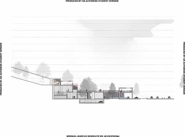
N. +15.00 N. +7.50N. +0.0 N. -4.0 0 20 40 60 100m Roof Floor Plan Section B - B´ Section C - C´ Shoping Center


VERSIONSTUDENTAUTODESKANBYPRODUCED PRODUCEDBYANAUTODESKSTUDENTVERSION VERSIONSTUDENTAUTODESKANBYPRODUCED PRODUCED BY AN AUTODESK STUDENT VERSION PDF.pc3ToDWG16:45:42,15/7/2020studio.dwg,thesisfinalTHESIS\examC:\Users\carla\Documents\FINAL +11.25+15.0+7.50+3.75+0.0-3.75 0 10 20 30 50m Section A - A´Isometry Landscape Isometry A B1 B A1


N. +0.0 N. +0.0 N. -13.1 N. -11.25 N. -3.75 N. -18.75 N. -7.5 N. -15.0 Spa Resort 0 20 40 60 100m Roof Floor Plan Section B - B´ Section C - C´


-18.75-11.25-7.50-3.75+0.0-15.0 VERSIONSTUDENTAUTODESKANBYPRODUCED PRODUCEDBYANAUTODESKSTUDENTVERSION PDF.pc3ToDWG16:46:17,15/7/2020studio.dwg,thesisfinalTHESIS\examC:\Users\carla\Documents\FINALB1B A1A Section AIsometryA´ Landscape Isometry


A BAC ED 43 2 1 17 181920 111097658 PRODUCED BY AN AUTODESK A BAC ED 43 2 1 17 181920 111097658 PRODUCED BY AN AUTODESK A BAC ED 43 2 1 17 181920 111097658 AUTODESKSTUDENTPRODUCEDVERSION BY AN AUTODESK A BAC ED 43 2 1 17 181920 111097658 AUTODESKSTUDENTVERSION A BAC ED 43 2 1 17 181920 111097658 AUTODESKSTUDENTVERSION A ED 111097658 A B Spa Resort Facade Detail

B C DE PISCINA JACUZZI DE 12 13 14 15 16 111097 Drainage layer _ 3cm Polymer modified bitumen sheet, 2 layers Thermal isolation_ 1.50cm Vapor Concretebarrierforslope_ 0.03cm 6 Bedding Mortar_ 1.50cm 5 Polished Concrete Floor_ 2cm 81416 Lightweight concrete screed_ 3cm Insulation matress_ 1.5cm Concrete floor units_ 32cm 13 Bedding Mortar_ 1.50cm 12 Polished Concrete Floor_ 2cm 15 Accesible rooftop construction Floor Retainingconstructionwallconstruction 3 Gravel filtrationlayerpipe drainage 2 Felt geotextile layer 1 Embankment 419 Thermal isolation_4cm Copper, titanium and zinc alloy sheet 18 Mortar filling_4cm 17 Precast concrete element 20 Ledge construction VERSIONSTUDENTAUTODESKANBYPRODUCED AUTODESK STUDENT VERSION B C DE PISCINA DE 12 13 14 15 16 111097 Drainage layer _ 3cm Polymer modified bitumen sheet, 2 layers Thermal isolation_ 1.50cm Vapor Concretebarrierforslope_ 0.03cm 6 Bedding Mortar_ 1.50cm 5 Polished Concrete Floor_ 2cm 81416 Lightweight concrete screed_ 3cm Insulation matress_ 1.5cm Concrete floor units_ 32cm 13 Bedding Mortar_ 1.50cm 12 Polished Concrete Floor_ 2cm 15 Accesible rooftop construction Floor Retainingconstructionwallconstruction 3 Gravel filtrationlayerpipe drainage 2 Felt geotextile layer 1 Embankment 419 Thermal isolation_4cm Copper, titanium and zinc alloy sheet 18 Mortar filling_4cm 17 Precast concrete element 20 Ledge construction VERSIONSTUDENTAUTODESKANBYPRODUCED AUTODESK STUDENT VERSION B C DE PISCINA DE 12 13 14 15 16 111097 Drainage layer _ 3cm Polymer modified bitumen sheet, 2 layers Thermal isolation_ 1.50cm Vapor Concretebarrierforslope_ 0.03cm 6 Bedding Mortar_ 1.50cm 5 Polished Concrete Floor_ 2cm 81416 Lightweight concrete screed_ 3cm Insulation matress_ 1.5cm Concrete floor units_ 32cm 13 Bedding Mortar_ 1.50cm 12 Polished Concrete Floor_ 2cm 15 Accesible rooftop construction Floor Retainingconstructionwallconstruction 3 Gravel filtrationlayerpipe drainage 2 Felt geotextile layer 1 Embankment 419 Thermal isolation_4cm Copper, titanium and zinc alloy sheet 18 Mortar filling_4cm 17 Precast concrete element 20 Ledge construction PRODUCEDBYANAUTODESK VERSIONSTUDENTAUTODESKANBYPRODUCED AUTODESK STUDENT VERSION B C DE PISCINA JACUZZI DE 12 13 14 15 16 111097 Drainage layer _ 3cm Polymer modified bitumen sheet, 2 layers Thermal isolation_ 1.50cm Vapor Concretebarrierforslope_ 0.03cm 6 Bedding Mortar_ 1.50cm 5 Polished Concrete Floor_ 2cm 81416 Lightweight concrete screed_ 3cm Insulation matress_ 1.5cm Concrete floor units_ 32cm 13 Bedding Mortar_ 1.50cm 12 Polished Concrete Floor_ 2cm 15 Accesible rooftop construction Floor Retainingconstructionwallconstruction 3 Gravel filtrationlayerpipe drainage 2 Felt geotextile layer 1 Embankment 419 Thermal isolation_4cm Copper, titanium and zinc alloy sheet 18 Mortar filling_4cm 17 Precast concrete element 20 Ledge construction PRODUCEDBYANAUTODESK VERSIONSTUDENTAUTODESKANBYPRODUCEDB C DE PISCINA JACUZZI DE 12 13 14 15 16 111097 Drainage layer _ 3cm Polymer modified bitumen sheet, 2 layers Thermal isolation_ 1.50cm Vapor Concretebarrierforslope_ 0.03cm 6 Bedding Mortar_ 1.50cm 5 Polished Concrete Floor_ 2cm 81416 Lightweight concrete screed_ 3cm Insulation matress_ 1.5cm Concrete floor units_ 32cm 13 Bedding Mortar_ 1.50cm 12 Polished Concrete Floor_ 2cm 15 Accesible rooftop construction Floor Retainingconstructionwallconstruction 3 Gravel filtrationlayerpipe drainage 2 Felt geotextile layer 1 Embankment 419 Thermal isolation_4cm Copper, titanium and zinc alloy sheet 18 Mortar filling_4cm 17 Precast concrete element 20 Ledge construction PRODUCEDBYANAUTODESK VERSIONSTUDENTAUTODESKANBYPRODUCED B C DE 12 13 14 15 16 111097 Drainage layer _ 3cm Polymer modified bitumen sheet, 2 layers Thermal isolation_ 1.50cm Vapor Concretebarrierforslope_ 0.03cm 6 Bedding Mortar_ 1.50cm 5 Polished Concrete Floor_ 2cm 81416 Lightweight concrete screed_ 3cm Insulation matress_ 1.5cm Concrete floor units_ 32cm 13 Bedding Mortar_ 1.50cm 12 Polished Concrete Floor_ 2cm 15 Accesible rooftop construction Floor Retainingconstructionwallconstruction 3 Gravel filtrationlayerpipe drainage 2 Felt geotextile layer 1 Embankment 419 Thermal isolation_4cm Copper, titanium and zinc alloy sheet 18 Mortar filling_4cm 17 Precast concrete element 20 Ledge construction A B C C 0 2 4 6 10m

The town of Vocemola is part of Ar quata Scrivia, a town in the province of Alessandria. “Appartata” which means isolated in English, is the first word used by the municipality of Arquata Scrivia when describing Vocemola. “Appartata”, due to its distance from the capital of the municipality to which it “Appartata”,belongs. for its complicated access. “Appartata”, due to its separation from the landscape due to the highway. When passing through the service area of the A7 motorway in the Scrivia Va lley, the eastern part of Vocemola can be slightly perceived, while the rest of the town is hidden by the lower level of the topography with respect to the motorway. The presence of the hi ghway has made Vocemola an isolated and dead-end destination. The people who will drive to it are currently only residents, as there is no other event that attracts external users to visit or just pass through the town of Vocemo la.The obstruction of the highway, to gether with the migration, has exposed the fragility of the territory. Unders tanding this fragility as “the quality of being easy to break” (Cambridge Dic tionary), this project intends to rein force the activity of the territory, thus combating a possible “breakdown” of the place.In order to achieve the goal, the strengths and weaknesses of the site were analyzed to determine the appropriate tools that would generate a positive transformation in the site. In the first place, Vocemola Service Area, along with the highway it ser ves, are determined as a weakness for its monotony and monodirectionality. Furthermore, the service area which can just exist as a wider extension of the motorway in form of platform, con tributes to territorial fragility as it is a space without any identity that can be compared to a non-place, where tra velers only stop momentarily to refill Ongasoline.theother hand, the natural context that surrounds the highway represents an opportunity factor for the reacti vation of these fragile territories, ta king into account the preference that many people currently have towards visiting nature in the face of significant urban growth. In the case of the A7 motorway, the natural context around it offers a landscape sequence, as the road climbs, descends and crosses di fferent valleys. In the closest area next to the highway the natural context is flatter and mostly used for agricultural purposes, as it moves away from the hi ghway the topography rises, becoming a potential natural area to explore but currently underused for recreational purposes due to its difficult access.
Rest and Walk over the A7 Motorway around the Vocemola Service Area
“Appartata, su un poggio oltre lo Scrivia, Vocemola conserva più di altre località aspetti e sapori di paese, con il borgo compatto attorno alla chiesa, le vecchie case ridipinte, i vicoletti, e, a brevissima distanza, monti e boschi.”
12
70
(Comune di Arquata Scrivia, n.d.)
Based on the above, this project pro poses to use the weaknesses as oppor tunities and take advantage of the exis ting strengths. In order to do this, the service area platform will be used, as the articulator between Vocemola, the highway and the orography, transfor ming the non-place into a place to visit and stay, attractive and accessible to external users (travelers of the A7 Mo torway) and internal users (residents from Vocemola and Arquata Scrivia), taking the great potential of the natural context as a possible role of landscape tourism in the reactivation of the town of Vocemola and its surroundings.
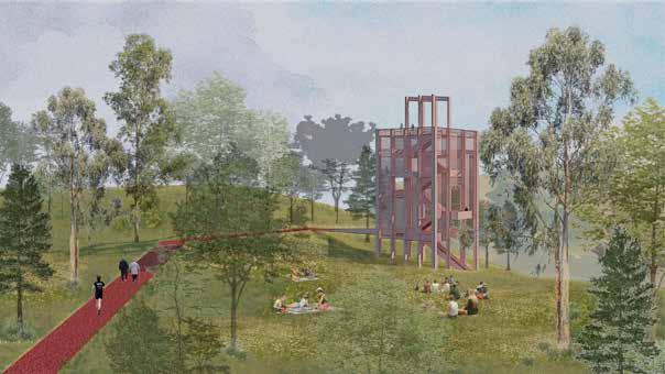
To achieve this, the built footpath will be used as the dynamic connector be tween Vocemola, the service area and the landscape, facilitating access to the user and offering an experience by wal king. Starting from Vocemola the built footpath which gives continuity to the existing path, now blocked by the hi ghway. Then, by crossing transversally the motorway, will connect Vocemola with the lanscape. And finally, will go into the mountain in order to explore it. Additionally, through open space ar chitecture, different type of interven tions are proposed in form of terraces and platforms providing more identity to the site and designed for resting, allowing the user greater proximity to


72 1 2 3 4 5 VERSIONSTUDENTAUTODESKANBYPRODUCED PRODUCEDBYANAUTODESKSTUDENTVERSION VERSIONSTUDENTAUTODESKANBYPRODUCED PRODUCED BY AN AUTODESK STUDENT VERSION Footbridge over A7 Motorway VERSIONSTUDENTAUTODESKANBYPRODUCED PRODUCEDBYANAUTODESKSTUDENTVERSION VERSIONSTUDENTAUTODESKANBYPRODUCED PRODUCED BY AN AUTODESK STUDENT VERSION VERSIONSTUDENTAUTODESKANBYPRODUCED PRODUCEDBYANAUTODESKSTUDENTVERSION VERSIONSTUDENTAUTODESKANBYPRODUCED PRODUCED BY AN AUTODESK STUDENT VERSION VERSION AUTODESK Gas Station Roof (Milan-Genoa) Gas Station Roof (Genoa-Milan) Masterplan1.Vocemola Bridge 2. Vocemola Town 3. Highway Service Area 4. Scrivia Torrent


73 0 50 100 150 250m 7 6 8 Torrent 5. A7 Motorway 6. Cable Car 7. Mountain Rest Area 8. Watchtower VERSIONSTUDENTAUTODESKANBYPRODUCED PRODUCEDBYANAUTODESKSTUDENTVERSION VERSIONSTUDENTAUTODESKANBYPRODUCED PRODUCED BY AN AUTODESK STUDENT VERSION VERSIONSTUDENTAUTODESKANBYPRODUCED PRODUCEDBYANAUTODESKSTUDENTVERSION VERSIONSTUDENTAUTODESKANBYPRODUCED PRODUCED BY AN AUTODESK STUDENT VERSION VERSIONSTUDENTAUTODESKANBYPRODUCED PRODUCEDBYANAUTODESKSTUDENTVERSION VERSIONSTUDENTAUTODESKANBYPRODUCED PRODUCED BY AN AUTODESK STUDENT VERSION STUDENT AN


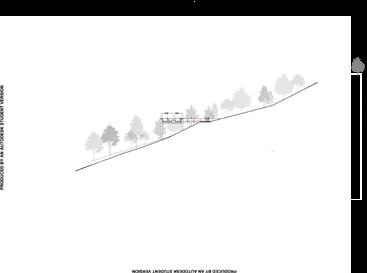
Deep stone filled trench 100 20-30NmmRedconcrete Crossfall 1/40100 mm granularCompated20-30NType1sub-baseGeotextile for filter purposeGround ContainmentLowWall 0 0.5 1 2m WALKWAY Raw Concrete pigmentation)(Red RawSTRUCTUREConcrete Mountain Footpath Footpath Section


75 Change of direction of the Footpath


Motorway Service Area Isometry


77 A7 Motorway III. 81 Longitudinal Section to the A7 Motorway Transversal Section to the A7Genoa-MilanGasMotorwayStationService AreaCable car Gas Milan-GenoaStation Vocemola Territory Built Footpath (Access from Vocemola) Gas Milan-GenoaStation Service Area 0 12 24 36 60m Ground Floor First Floor


VERSIONSTUDENTAUTODESKANBYPRODUCED PRODUCEDBYANAUTODESKSTUDENTVERSION VERSIONSTUDENTAUTODESKANBYPRODUCED PRODUCED BY AN AUTODESK STUDENT VERSION C D +10.00 +15.00 +13.00 +5.00+8.00+0.00 +10.00 +15.00 +13.00 +8.00 +5.00 +0.00 Section C - C1 Section D - D1 Motorway Service Area


VERSIONSTUDENTAUTODESKANBYPRODUCED PRODUCEDBYANAUTODESKSTUDENTVERSION VERSIONSTUDENTAUTODESKANBYPRODUCED PRODUCED BY AN AUTODESK STUDENT VERSION A B +15.00+15.00+10.00+10.00+5.00+5.00+0.00+0.00 -3.00 0 6 12 18 30m Shopping Center Section A - A1 Section B - B1


80 CONSTRUCTIVE COMPOSITION FOOTPATH [2] - Metallic structure with a thin layer of concrete covering on the top layer FACADE AND GAS STATION STRUCTURE -[3][4]PPC Aluminium lined metal structure with fixed glazing - Perforated PPC aluminum panels for TERRACEhandrails FLOOR [1] - Reinforced concrete slab with steel FIRSTbeamsFLOOR AND INTERIOR WALLS [1] - Reinforced concrete slab with steel -beamsSolid walls made with precast concrete GROUNDpanels FLOOR SLAB AND INTERIOR WALLS [1][3] - Reinforced concrete slab - Solid walls made with precast concrete panels and glass walls with aluminium MAINprofilesSTRUCTURAL ELEMENTS [1] - Reinforced concrete retaining wall towards topography - Steel and concrete composite colum ns on the main building - Reinforced concrete support points for pedestrian bridge VERSIONSTUDENTAUTODESKANBYPRODUCEDVERSIONSTUDENTAUTODESKANBYPRODUCED VERSION PRODUCED BY AN AUTODESK STUDENT VERSION Exploded Isometry 5 10 20m Motorway Service Area [2] Raw Concrete (Red pigmentation) [1] Raw Concrete [3] PPC (LightAluminiumpinktone) Perforated[4] (LightAluminiumPPCpinktone)


81 The Path into the Building VERSIONSTUDENTAUTODESKANBYPRODUCED PRODUCEDBYANAUTODESKSTUDENTVERSION VERSIONSTUDENTAUTODESKANBYPRODUCED


82 Triangular Courtyard Shopping Center InteriorVERSIONSTUDENTAUTODESKANBYPRODUCED PRODUCEDBYANAUTODESKSTUDENTVERSION


83 Circulation on ground floor VERSIONSTUDENTAUTODESKANBYPRODUCED PRODUCEDBYANAUTODESKSTUDENTVERSION

VERSIONSTUDENTAUTODESKANBYPRODUCED PRODUCEDBYANAUTODESKSTUDENTVERSION
VERSIONSTUDENTAUTODESKANBYPRODUCED PRODUCEDBYANAUTODESKSTUDENTVERSION
VERSIONSTUDENTAUTODESKANBYPRODUCED PRODUCED BY AN AUTODESK STUDENT VERSION
PRODUCEDBYANAUTODESKSTUDENTVERSION
VERSIONSTUDENTAUTODESKANBYPRODUCED PRODUCEDBYANAUTODESKSTUDENTVERSION
VERSIONSTUDENTAUTODESKANBYPRODUCED PRODUCEDBYANAUTODESKSTUDENTVERSION
VERSIONSTUDENTAUTODESKANBYPRODUCED PRODUCED BY AN AUTODESK STUDENT VERSION
VERSIONSTUDENTAUTODESKANBYPRODUCED PRODUCED BY AN AUTODESK STUDENT VERSION
VERSIONSTUDENTAUTODESKANBYPRODUCED
VERSIONSTUDENTAUTODESKANBYPRODUCED PRODUCED BY AN AUTODESK STUDENT VERSION
VERSIONSTUDENTAUTODESKANBYPRODUCED PRODUCEDBYANAUTODESKSTUDENTVERSION
VERSIONSTUDENTAUTODESKANBYPRODUCED PRODUCED BY AN AUTODESK STUDENT VERSION
VERSIONSTUDENTAUTODESKANBYPRODUCED PRODUCEDBYANAUTODESKSTUDENTVERSION
VERSIONSTUDENTAUTODESKANBYPRODUCED PRODUCED BY AN AUTODESK STUDENT VERSION
VERSIONSTUDENTAUTODESKANBYPRODUCED PRODUCED BY AN AUTODESK STUDENT VERSION Cable Car Exit Exit to the direct connection with the Mountain Rest Area Access from the terrace of the Service Area Building Cable Car Access (+10) (+100) (+185) (+70) (+160)(+40) (+130) Rest Area and Cable Car structure Cable Car
84


85 Type Facade Type Section 0 2 4 6 10m


1. Shadow Rest Area 2. Cable Car Access 2 1 Isometry Moountain Rest Area


VERSIONSTUDENTAUTODESKANBYPRODUCED PRODUCEDBYANAUTODESKSTUDENTVERSION VERSIONSTUDENTAUTODESKANBYPRODUCED PRODUCED BY AN AUTODESK STUDENT VERSION E G F +3.00 +3.00+0.00 +5.00 +0.00 +5.00+0.00 0 8 16 24 40m Section E - E1 Section F - F1 Section G - G1


88 CONSTRUCTIVE COMPOSITION FOOTPATH [1][2] - Pre-cast concrete low retai ning wall towards topography - Cast on site concrete for the STRUCTUREfloor Platform [3][4] - PPC Aluminium lined metal -structurePerforated PPC aluminum panels for handrails Cable Car [1] - Semi-circular precast compo site PLATFORMSelement [1] - Reinforced concrete slab VERSIONSTUDENTAUTODESKANBYPRODUCEDVERSIONSTUDENTAUTODESKANBYPRODUCED 10 20 40m Exploded Isometry Moountain Rest Area [2] Raw Concrete (Red pigmentation) [1] Raw Concrete [3] PPC (LightAluminiumpinktone) Perforated[4] (LightAluminiumPPCpinktone)
89 Half way stop VERSIONSTUDENTAUTODESKANBYPRODUCED PRODUCEDBYANAUTODESKSTUDENTVERSION VERSIONSTUDENTAUTODESKANBYPRODUCED PRODUCED BY AN AUTODESK STUDENT VERSION


Watchtower Isometry

VERSIONSTUDENTAUTODESKANBYPRODUCED VERSIONSTUDENTAUTODESKANBYPRODUCED PRODUCED BY AN AUTODESK STUDENT VERSION +7.50+2.50 +10.00+5.00+0.00 +12.50 Section H - H1 Floor Plans 0 4 8 12 20m (+7.50) (+10.00) (+12.50) (0.00) (+2.50) (+5.00)


92 CONSTRUCTIVE COMPOSITION FACADE [4] - Perforated PPC aluminum panels STRUCTURE [3] - PPC Aluminium lined metal columns FLOORS [3] - Laminated steel plate STAIRCASE [2][3] - Metallic structure with a thin layer of concrete covering on the top layer - Laminated steel plate for the handrails FOOTPATH [2] - Cast on site concrete for the floor VERSIONSTUDENTAUTODESKANBYPRODUCEDVERSIONSTUDENTAUTODESKANBYPRODUCED VERSIONSTUDENTAUTODESKANBYPRODUCED 10 20 40m Watchtower Isometry [2] Raw Concrete (Red pigmentation) [3] PPC (LightAluminiumpinktone) Perforated[4] (LightAluminiumPPCpinktone)
93 End of the Path VERSIONSTUDENTAUTODESKANBYPRODUCED PRODUCEDBYANAUTODESKSTUDENTVERSION VERSIONSTUDENTAUTODESKANBYPRODUCED


ACADEMIC WORK