5 minute read
Valve Lockout
What is a Gate Valve Lockout?
A simple solution for isolating gate valves. Once the valve is in the appropriate position, simply slip the Lockout over the top of the handle, rotating freely around the valve stem and thus preventing access and movement of the valve.
The different sizes cover the most commonly used valve diameters. Where a Gate Valve Lockout cannot be used due to fitting or other restraints, consider using a Cable Lockout system to isolate the valve (see page 169 for our full range of Cable Lockouts). • Resistant to cracking and abrasion. • Dielectric properties. • Rotates freely around valve handles. • Resistant to extreme temperatures. • Suitable for hasps and padlocks. • Available in various sizes.
Using a Gate Valve Lockout
Slip the Lockout over the top of the valve handle. Once in position the cover will rotate freely thereby preventing the valve from turning.
Directions For Use:
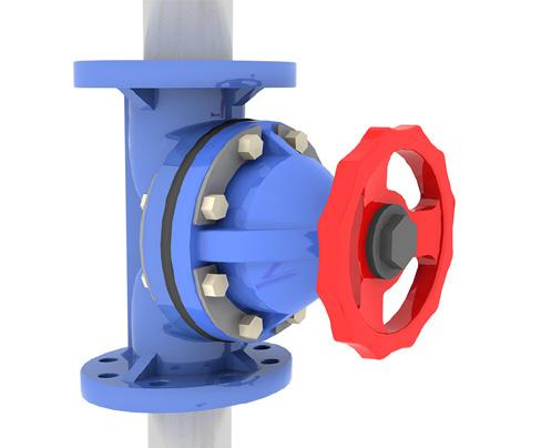
Step 1
Ensure the valve is in the required locked off position (on/off). Select the appropriate sized Lockout for the gate valve.
Step 1b (Optional)
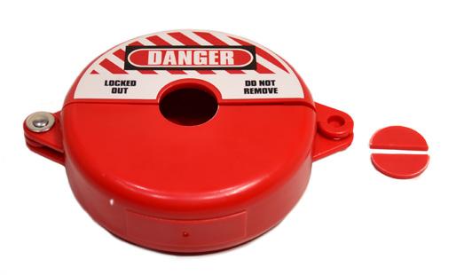
Optional clip out centre. Please specify if you would like the Lockout with pop out centre when placing your order. (For use on valves with a rising stem).
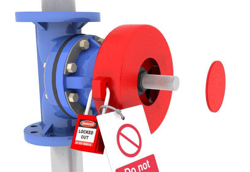
Step 2
Place the Lockout device over the valve wheel and close, ensuring it can rotate freely around the wheel.
Step 3
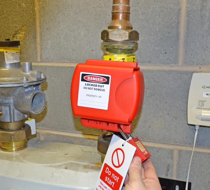
Secure Lockout with a safety padlock and attach a tag to communicate your chosen safety message. Use a hasp if more padlocks are required.
Gate Valve Lockout
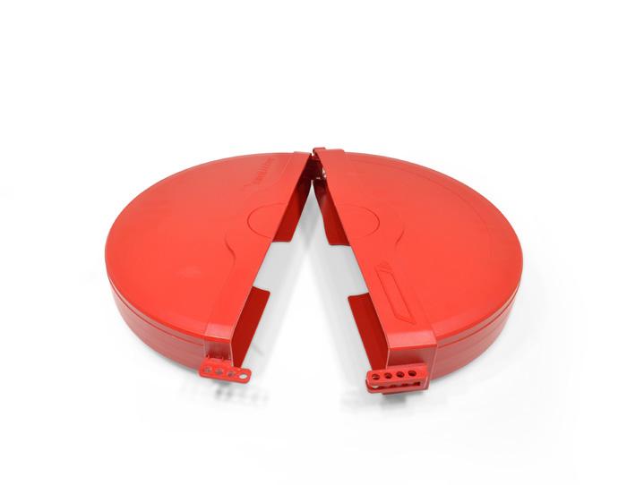
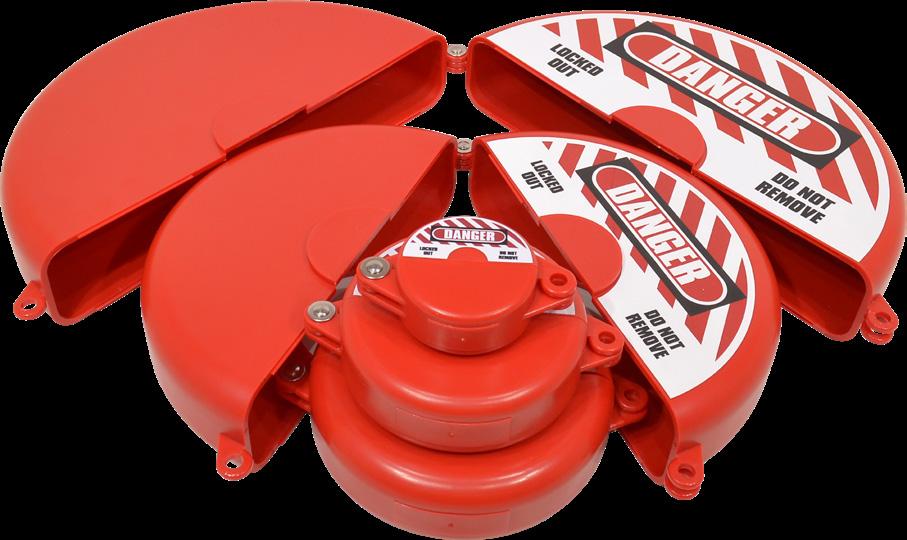
Comprising of 2 flattened half moons with a hollow centre. Hinged at one side, they are placed over the valve and then closed, ensuring that the valve wheel is tamper-proof. Use a hasp if more than one padlock is required to Lockout the device.
(Millimetres) (Inches) Code
25 - 63.5mm 1” - 21/2” 5581080 63.5 - 127mm 21/2” - 5” 5581081 127 - 165mm 5” - 61/2” 5581082 165 - 254mm 61/2 - 10” 5581083 254 - 355mm 10” - 14” 5581084
Please ask if you require the Gate Valve Lockout with a clip out centre.
Dimensions (A) (B) (C) (D) (E)
25 - 63.5mm 70 32 76 38 N/A
63.5 - 127mm 130 34 140 44 33
127 - 165mm 170 41 177 50 53
165 - 254mm 257 50 267 63 70
254 - 355mm 355 63 368 74 74
(A) Inside diameter (B) Inside depth (C) Outside diameter (D) Outside depth (E) Inner hole diameter
A
E
C
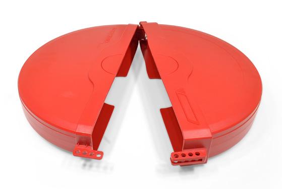
Extra Large Gate Valve Lockout
Our largest sized Gate Valve Lockout is suitable for valve handles with a diameter of 330mm up to 450mm. It has an integral clip out centre and a built in facility to use up to 4 padlocks without the need for a hasp.
When not in use one side of the Lockout fits within the other for transportation and storage.
Size (Inches) Code
330 - 450mm 13” - 18” 5570011
Dimensions (A) (B) (C) (D) (E)
330 - 450mm 470 75 475 90 90
(A) Inside diameter (B) Inside depth (C) Outside diameter (D) Outside depth (E) Inner hole diameter All sizes in minimeters
A
E
C
B D
Adjustable Gate Valve Lockout
2 separate pieces which slide over the valve and lock together. Fits valve hand wheels between 25.5mm and 165mm in diameter.
Size (Inches) Code
25.5 - 165mm 1” - 61/2” 5581090
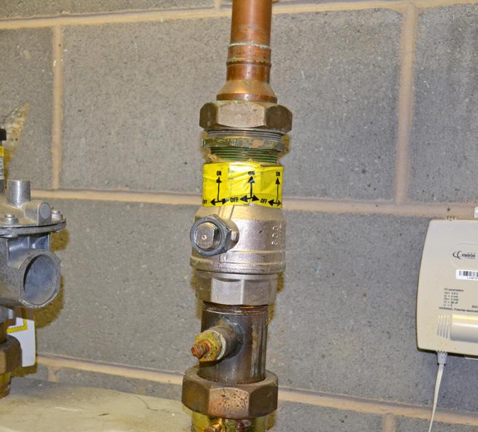
What is a Ball Valve Lockout?
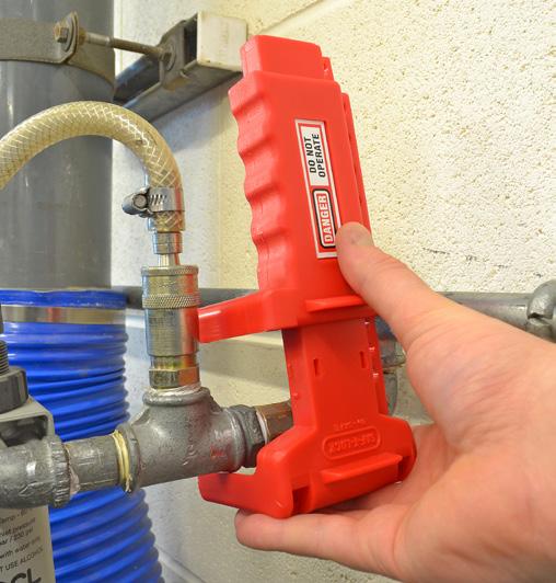
Using Ball Valve Lockouts
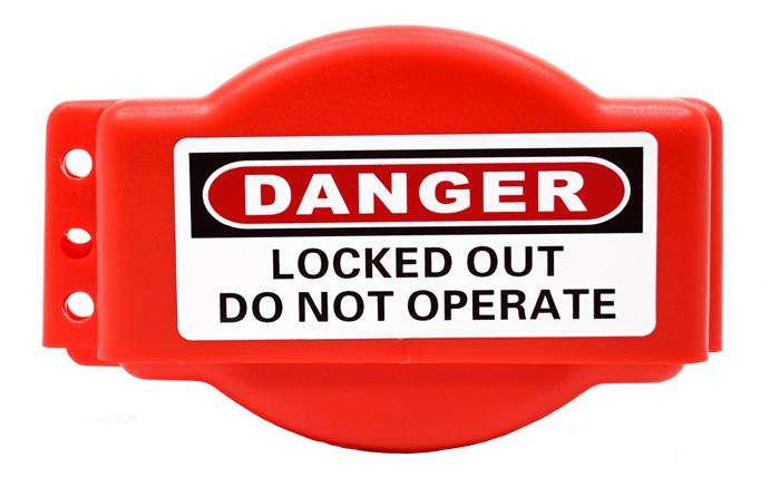
Once in the correct isolated position, the handle of the valve is trapped within the body of the Lockout, preventing the handle from being operated.
Please note: Holes on the slider section have a staggered repeat which ensures that at least one hole will be tight when placed against the valve. If more than one padlock is required then a hasp should be used.
Directions For Use:
Step 1
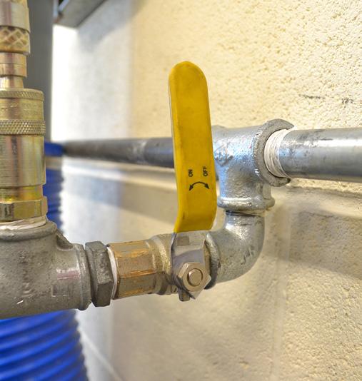
Turn the valve handle to the correct position - either on or off.
Step 2
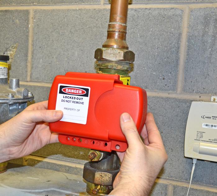
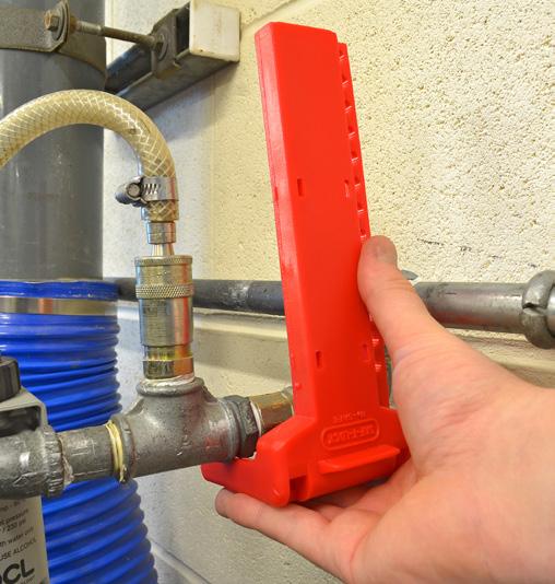
Lockout the device by placing the main body over the top of the valve handle. Ensure the valve handle sits inside channel.
Step 3
Move slider section down the shaft of the Lockout until tight against the valve body.
Step 4
Insert a padlock or hasp through the most appropriate hole which keeps the slider secure.
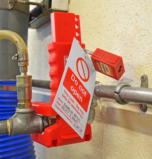
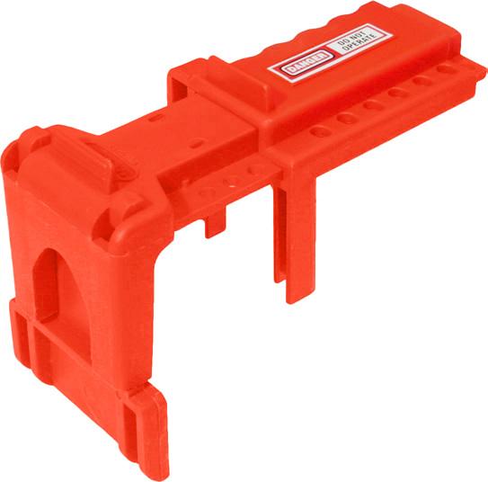
Ball Valve Lockout
Size Code
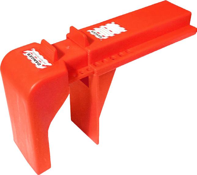
9.5 - 31mm 5581150 32 - 63mm 5581151 50 - 203mm 55F3202
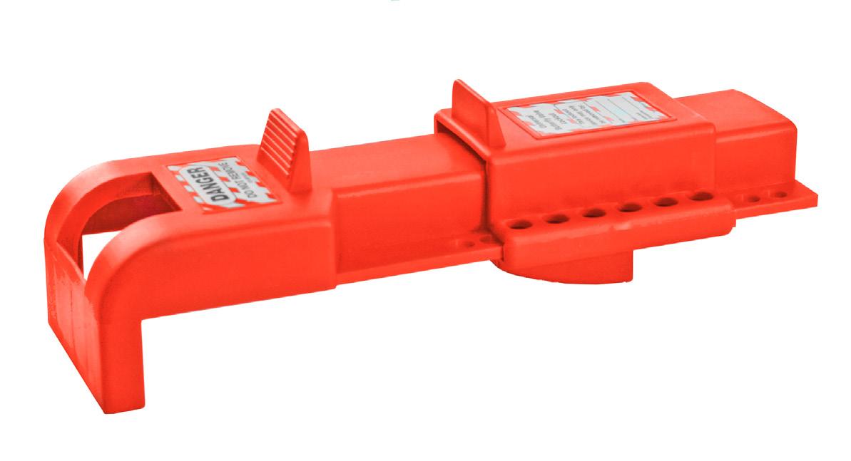
Butterfly Valve Lockout
When slid into position the wedge on the slider section prevents the compression handle being squeezed, preventing operation of the valve. Working in a similar way to the standard Ball Valve Lockouts, the wedge on the slider section sits between the compression handle and lever, preventing operation.
Size Code
8 - 45mm 5581160
Flange Ball Valve Lockout
Once the flange ball valve is in the desired position and the handle removed, this Lockout device fits over the top of the stem ring.
The two sections of the device slide together over the top of the stem, ensuring it is suitable for various sizes of valves. Hole size: 46 x 38mm
Size Code
150 x 220 x 70mm 5570106
Directions For Use:
Step 1 Step 2 Step 3
