3 minute read
Charge Ahead in Battery Design with COMSOL Multiphysics®


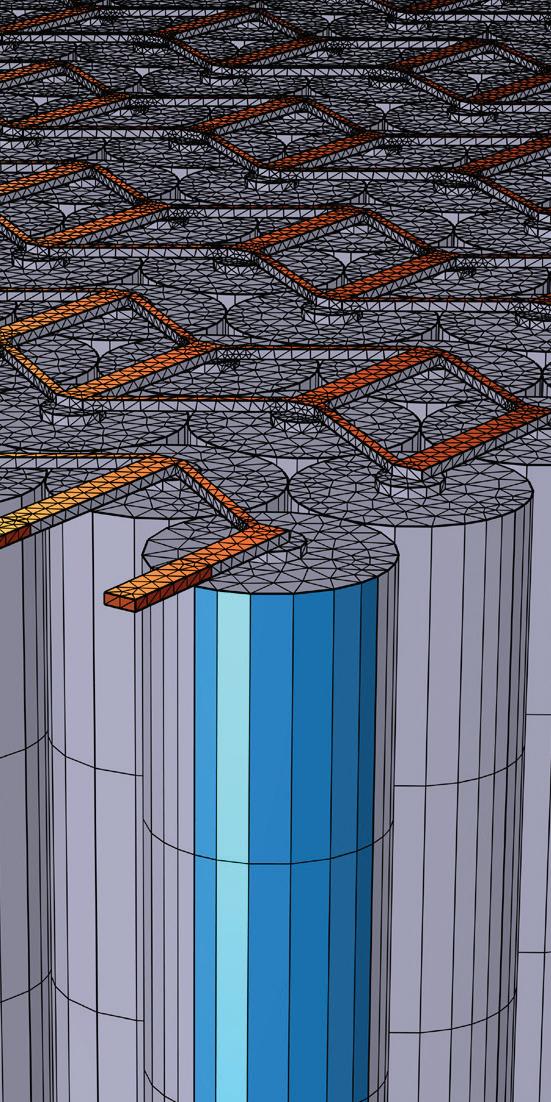
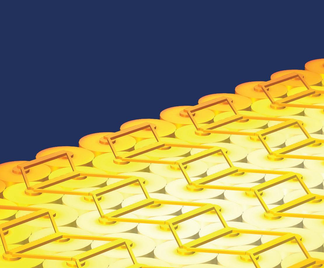
Multiphysics simulation helps in the development of innovative battery technology by providing insight into mechanisms that impact battery operation, safety, and durability. The ability to run virtual experiments based on multiphysics models, from the detailed cell structure to battery pack scale, helps you make accurate predictions of real-world battery performance.
» comsol.com/feature/battery-design-innovation


(IPM-SynRM), which combines the buried magnets of the Interior PM Synchronous Motor (aka IPM-SM) with the rotor structure of the reluctance motor. Basically, the IPM-SynRM behaves pretty much like the IPM-SM as far as the inverter is concerned, but with a signi cant contribution from reluctance torque (more on what that is below). In both the IPM-SynRM and IPM-SM, burying the rotor magnets also partially shields them from heat as well as demagnetization from the stator (during overloads and eld weakening) and also eliminates the risk of being ung o the rotor at high rpm, as is the invariable case for the surface PM construction (that, to be fair, is rarely used in EVs these days). Both Toyota and Tesla have reportedly started using this type of motor, albeit not exclusively.
Moving along the continuum from the pure synchronous motor to the IPM-SM, then the IPM-SynRM, we nally come to the pure reluctance motor, which operates only on the attraction between electromagnets in the stator and a magnetically-so iron or steel rotor. Reluctance is the magnetic analog to resistance, so a magnetic circuit with minimum reluctance occurs when magnetic eld lines can freely ow from the North to South poles. is condition occurs in a reluctance motor when a diametrically-opposed pair of electromagnets on the stator align with a matching pair of projecting teeth on the rotor (maximum reluctance occurs when the rotor teeth are between two pairs of stator poles). By constructing the rotor with fewer teeth (or salient poles) than the stator (e.g. 4 rotor poles to 6 stator poles), it can be ensured that when some salient poles are aligned with the stator electromagnets, some will be in between them. Sequentially energizing the stator electromagnets—switching from one pole pair to the next, hence the more common name of Switched Reluctance Motor—will cause the rotor to rotate in much the same fashion as in a PMSM or ACIM. One crucial di erence in the SRM, however, is that the stator electromagnets are supplied with a trapezoidal but unipolar (DC) current waveform, rather than a bipolar (AC) one. is means there are no iron losses in the rotor, which is a huge plus, but the torque output has a lot of ripple, and this subjects the rotor to immense tension and compression, which can then cause vibration and noise. It also means that the classic half-bridge power stage used for each phase in an inverter/VFD isn’t the best choice here; rather, a two-switch, two-diode power stage is preferred, as it can rapidly increase the winding current, and just as rapidly decrease it (while recycling any energy still stored in the winding inductance back to the battery).
Another issue that has hampered the adoption of reluctance motors until recently is the fact that the current through the stator electromagnets must be ramped up rapidly and with precise timing as a given rotor pole pair comes into alignment with a stator pole pair, then held at a de ned level for a few degrees of rotation, and then rapidly ramped down again as that rotor pole pair rotates out of alignment. is requires very accurate knowledge of the rotor position, which generally means a relatively expensive (and relatively delicate) absolute encoder, and as if that weren’t enough, the inductance of the stator electromagnets increases as a rotor pole pair comes into alignment (because the reluctance drops, and inductance is inversely proportional to reluctance), which makes increasing the current that much more di cult, especially given the fact that the dI/ dt (i.e. rate of change in current over time) must be carefully controlled for optimum torque production. is requires a lot of computing power, but fortunately, modern microcontrollers and Field-Programmable Gate Arrays (FPGAs) have more than sucient grunt for the task. Consequently, the SRM is bound to be the dominant EV traction motor of the future… Any day now, I’m sure…
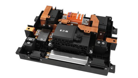
Power levels in electric vehicles are increasing. EVs need to drive farther and charge faster. What does this mean for system safety? Expertise is critical when managing, distributing and protecting electrical systems. Eaton’s advanced battery disconnect units (BDUs) feature integrated Breaktor® circuit protection technology, enabling EV manufacturers around the globe to deliver the safest vehicle systems possible.


Because that’s what matters.


