17 minute read
SAUBER TECHNOLOGIES


From a privateer race team to one of the biggest players in the industry, Racecar charts the evolution of Sauber’s engineering groups
By Stewart Mitchell
Axel Kruse, CEO of Sauber Technologies
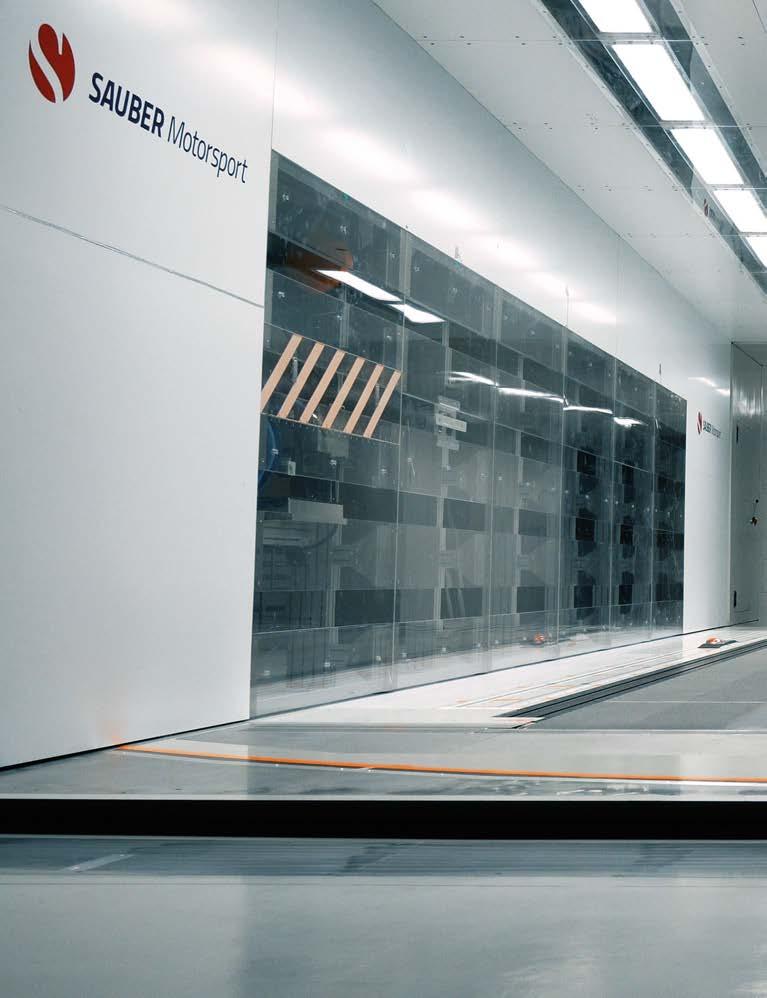
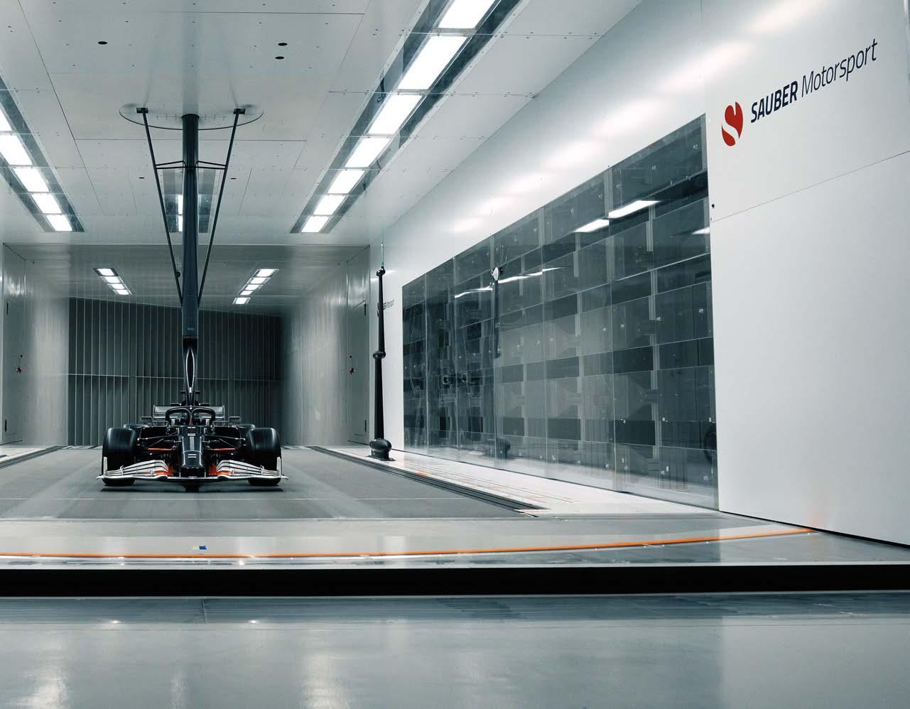
Sauber’s wind tunnel is one of the best known and widely used of its type in motorsport today. This impressive facility now forms part of the newly formed Sauber Technologies
Forward thinking
Leveraging a Formula 1 team’s engineering expertise and DevOps capabilities for other applications is nothing new. Teams up and down the grid have formed race team partner firms to sell their services to outside organisations for many years. However, this part of Formula 1 has evolved significantly over the past couple of years to accommodate the cost cap regulations and keep the staff’s amassed engineering expertise in house.
The Alfa Romeo Formula 1 team is run by Sauber Motorsport, part of the Sauber Group based in Hinwil, Switzerland. The start of 2022 saw the birth of Sauber Technologies, a new company devoted to bringing Sauber’s engineering innovation and Formula 1 mindset to businesses worldwide. Sauber Technologies incorporates Sauber Engineering and Sauber Aerodynamics, which have both been around for a while, strengthening their capabilities for customers across a broad range of industries.
‘In the past, we had three entities in the company: the motorsport pillar, aerodynamics and engineering,’ explains Axel Kruse, CEO of Sauber Technologies. ‘The engineering, which is the base of the Sauber Technologies group, came from our recognition of us having an excellent product in engineering expertise and being very strong in additive manufacturing (AM).
‘We’ve been pushing AM very hard because we recognise its potential for supply of the wind tunnel testing components and realising our designs in the real world before they go to final manufacture. With the introduction of the budget cap, it made sense to merge the aerodynamic and engineering capabilities as they are hand in hand. So, we created the Sauber Technologies arm of our company.’
There and back
The evolution of the Sauber Group started in 1970 when Swiss businessman, Peter Sauber, founded Sauber Motorsport. After various stints in a multitude of racing
disciplines, from hillclimbing through to Sportscars, the team entered Formula 1 in 1993. After failing to make much of an impression as an independent outfi t, Sauber sold the team to BMW in 2005. It then competed as BMW Sauber from 2006 to 2009, scoring one victory.
Then, when BMW pulled out of Formula 1 at the end of the 2009 season, Peter Sauber bought his old team back again, and it was granted a 2010 entry.
The BMW Sauber project had resulted in a substantial increase in competitiveness for the team. Third party engineering work was always a strong pillar for Sauber, but its reliance on engineering output increased with the withdrawal of BMW’s funding. Today, Sauber Technologies is its own entity, entirely dedicated to third party business, though one of its biggest customers is Sauber Motorsport (currently the Orlen Alfa Romeo Formula 1 team).
Within the Technologies arm, the company has fi nite element analysis (FEA) and computational fl uid dynamics (CFD) capacity, milling and other subtractive manufacturing solutions, additive manufacturing (AM) capability and wind tunnel services, able to run from full-size cars down to 50 per cent scale models.
Clear vision
‘With this capability, alongside our consulting within those areas, we can support companies with a clear vision who want to execute their programme from taking a blank sheet of paper and ideas to full production,’ explains Kruse.
Sauber Technologies’ additive manufacturing capability was born out of the high demand for test parts to be made quickly and accurately. When BMW bought the Formula 1 team, it brought with it a signifi cant budget. The Sauber Group management therefore put together a plan for team to improve effi ciency across all its operations. Part of that drive was to stop outsourcing the production of wind tunnel components. That desire saw Sauber build up its additive manufacturing department internally, initially for plastic parts for Sauber Motorsport produced via stereo lithography (SLA) and selective laser sintering (SLS) techniques.
‘Early on in our additive manufacturing journey, we discovered some parts on the full-scale car we wanted to print, but the material was not available in the quality we needed,’ notes Kruse. ‘For example, for the Monaco GP, you need the front brake ducts to have the maximum ducting because of the high number of braking zones and the low fl ow fi eld velocity through the front braking system. But you only need this confi guration for that race once a year.
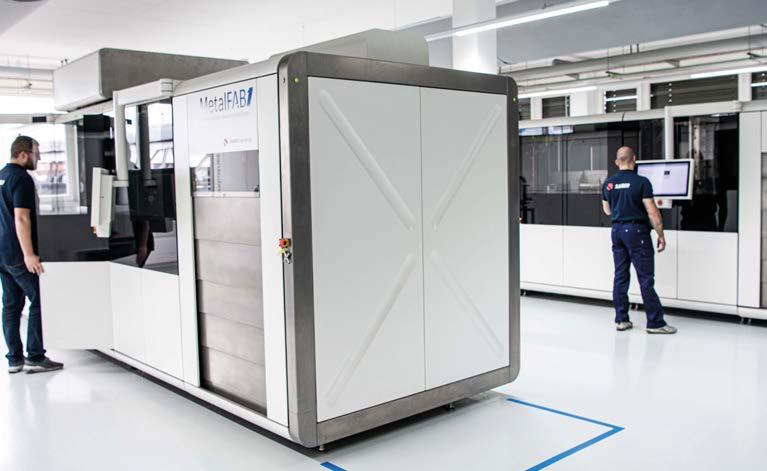
Additive Industries’ modular and scalable MetalFAB1 system, designed for integrated and automated production with metal powder bed fusion technology using four lasers
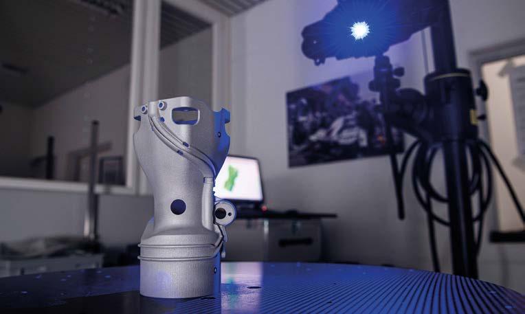
After an AM part is manufactured and processed, it is laser scanned and compared to the original CAD file to ensure no discrepancies
‘In the past, we built Monaco GP brake ducts from virgin carbon fi bre. The process included positive and negative laminating followed by milling, and then you have six sets for the two cars for that weekend. The design would evolve for the following year, so the tooling would be a waste. We wanted to print them because it’s a one off , but we had to fi nd a material temperature resistant enough to do that. So we developed our own.’
The company’s proprietary HiPAC SLS material was the result. It is based on a carbon-reinforced polyamide 12 and off ers high mechanical properties and dimensional stability, with low water absorption compared to other polyamides, making it barely aff ected by moisture.
Outside of the niche Monaco brake duct application, Sauber saw a market demand for such a material in diff erent applications.
‘So, we ramped up the plastic AM capacity to supply the needs of the Formula 1 applications [wind tunnel testing and some additional parts on the car] and third-party market demand,’ Kruse explains. ‘We bought six SLA and six SLS machines to cope with the demand as it came in.’
Material composition
With Sauber an early adopter of the then new AM techniques within the Formula 1 fraternity, it also pioneered material composition, alongside powdered material manufacture. The powdered material evolution has been rapid, although many of the exotic materials used to exploit performance in high-end industries are banned in Formula 1.
On the plastic AM side, Kruse says there’s always something new coming. For example, Sauber Technologies is currently doing a lot of work with carbon fi bre-reinforced PA12 material. The reason is that it’s so versatile, and engineers can manipulate its composition to fulfi l a wide range of diff erent demands. Its most signifi cant strength is its hightemperature stability when compared to other AM plastics – up to 170degC.
The fi bre orientation cannot be stipulated in manufacturing fi bre-reinforced polymers produced using current AM. That means engineers cannot optimise the internal structure for the number of fi bres and load directions the part will experience during operation. However, the part’s shape can be designed to be more optimised for the application, thanks to the almost limitless construction freedom of AM. That means some of the strength lost from the lack of fi bre orientation in the material structure can be compensated for by good design.
‘After many trials, you learn what is the right number of fi bres over that part,’ explains Kruse. ‘Everywhere across the part has the same density of fi bres, and so the same strength, because you can’t orientate them.’
Metal AM
Soon after the plastic AM side of the business took off , Sauber began investigating the potential of metal additive manufacturing. At the time, the technology was immature, and a lot of expertise was required to make parts successfully using this technique. Consequently, Sauber decided it needed a partner for this venture, which it found in Dutch fi rm Additive Industries. Today, they are a principal partner to Sauber Technologies, providing a series of metal AM technologies, including the machines and the software to produce metal AM components. Finding a partner in Additive Industries also saw the company install four metal printers to print titanium, specially strengthened aluminium and stainless steel.
Metal AM machines work with a vast array of powdered materials, so improving the performance of AM-produced parts is down to the laser parameters and environment around the part during production.
‘We are focusing on the metals usable for Formula 1 in metal AM and exploiting what we know for third party business,’ notes Kruse. ‘Formula 1 wants to keep a stable bill of materials. The management does not want a situation where things like beryllium are used again, and the costs ramp up. They have a strict catalogue of what is available to use, so there’s little point in exploring anything else outside those specifi ed materials.
‘Metal AM was a huge shift in capabilities for the Formula 1 application as a vast number of components on the car could now be printed.
‘This was a massive milestone for the technology and us as a supplier of these elements, but there was still a steep learning curve to climb. Early on, there was quite a disparity between the performance of an additive manufactured part compared to a part subtractive manufactured from a billet of material. To further optimise the AM components, we needed to develop our design approach for manufacture with AM in mind. Our technology and FEA programming has evolved to the point where we are designing in a completely diff erent type of way to accommodate the potential of AM.’
Additive manufacturing has a series of positive knock-on eff ects outside of the lack of material waste and the potential to optimise shapes stemming from the freedom in design it off ers. It allows users to reduce considerably the number of milling machine cutters required, and the produced parts are often lighter, so cheaper to transport. Engineers can also now achieve integrated features with four or fi ve functions within one AM component, rather than producing several parts from subtractive manufacturing that go together into an assembly. As such, part count on a given system can be reduced, meaning storage departments can reduce their capacity, too.
Finally, lead times for AM components are signifi cantly less than other manufacturing techniques.

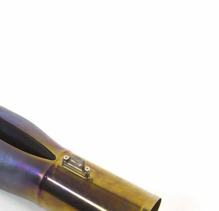
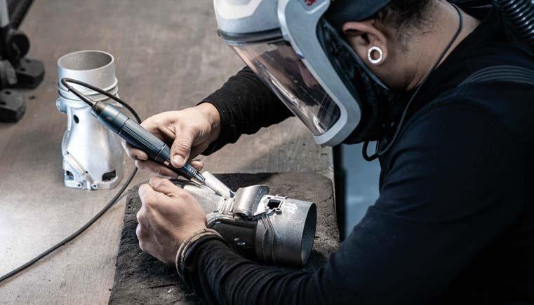
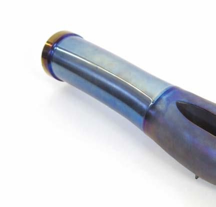
Titanium additive manufacturing is a major development for Sauber Technologies. Here’s a post-turbine exhaust part for a contemporary turbocharged, 1.6-litre, V6 Formula 1 engine
Axel Kruse
Techniques for AM
When the part is being layered during the AM process, the fi rst layer will heat cycle more than the top layer if the build chamber environment isn’t properly managed. Making sure the heat distribution is even throughout the part, therefore, so there’s no additional stress placed upon the fi rst layers compared to the top layers is critical for part performance when it goes into service.
‘We’ve worked very hard to develop working practices for AM throughout this journey,’ remarks Kruse. ‘Working out what the right chamber and build platform temperature should be when you start is critical to how the layers bond during construction. And this process is different from material to material. We print several millimetres before the formation of the main structure begins because we cut the part off the build platform, and this support structure will take the heat away from the part and into the platform.
‘If you are building a complex structure, any overhanging or long lateral forms must be supported by structures underneath them. We design the manufacturing process so the machine prints these support structures, and they have several roles. Their primary function is accurately mechanically supporting the part, but they must also effectively draw heat away from the component body, and also need to easily break away, or grind away, from the main feature in post-processing.’
The secondary and tertiary roles are more intensive in engineering than mechanical handling. ‘We carry out in-depth finite element analysis and simulation to identify how the part’s mechanical and thermal stress comes out through the support structure, and ensure when we cut it out that it’s not going to damage the part,’ continues Kruse. ‘Proprietary design techniques are used to ensure the heat from the build follows a given support structure path away from the part body better than through the part itself.
‘We simulate this in the design programme we use: where the support structure contacts the part, where the heat goes, where the mechanical forces go, and the interface between the support structure and the part is defined extremely accurately. Then we will optimise that to ensure the part can go into service as soon as possible after the build.
‘Additionally, using the build platform most efficiently is critical, because the money you’re spending is mostly machine running time. So, you have a platform size with several parts and different structures, which should not interfere with all the others. Yes, this is the tricky thing.’
Engineering consultancy
Despite the manufacturing side of Sauber Technologies being a significant element of the business, the largest growth area for the company has been in engineering consulting. In the beginning, the consulting arm was around 30 per cent of the output, and now it’s over 50 per cent, with far more customers.
‘The engineering, consulting and project management is growing very fast,’ says Kruse. ‘Very often, these projects are combined with the AM technology or wind tunnel facility, making our company a one-stop shop for all the required parts of a project.’
Of the consulting side of things, Kruse says the competitive edge for the engineering side of the Technologies group is its design for AM capabilities. ‘I think it’s a big move, especially when talking with the designers, because they often think in structures they know. But when designing for AM, you must come from the other side, focusing only on what is necessary for the specification of the part, not thinking about what it should look like. This is a different type of thinking. It’s also a lot of learning to give the designer confidence that we can do that.
‘In Formula 1, speed of learning is everything, and we have a very high learning curve. To maximise this, we have dedicated programmes on the AM machines to do pre-development for the Formula 1 team, including testing. We have invested a lot of money in test facilities and equipment to carry out tensile strength tests and finished part tolerancing to verify the material and its properties.
‘Because the AM techniques we use have a powder bed and are created by melting that powder in layers, you must make sure everything is consistent from top to bottom, and you have to test it. When we started, the testing methodology for this technology was not available. We had to develop it ourselves.’
Axel Kruse
Wind tunnel
Perhaps the most well-known part of the Sauber Technologies group is its wind tunnel facility. It boasts cutting-edge technology for all relevant aspects: wind speed, size of the test section, rolling road, model motion system and data collection. The tunnel has a maximum tube diameter of 9.4m and is designed as a closed circuit, measuring 141m in length (without the test section). The overall weight of all the steel elements, plus the fan housing, comes to 480 tonnes. The single-stage axial fan with carbon rotor blades is state of the art.
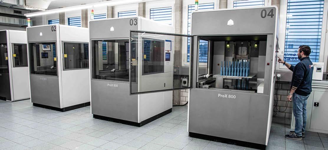
Sauber Technologies has invested heavily in AM technology in recent times. Shown here is its four stereolithography (SLA) polymer additive manufacturing machines
At the heart of the wind tunnel is the test section. It is generously proportioned to provide representative racing conditions for precise results. Testing with a full-scale racecar is possible and consequently it is used by many third-party clients.
However, current regulations ban full-scale testing in Formula 1 and some other racing series, so F1 exclusively uses 60 per cent scale models for wind tunnel testing work.
The entire measuring platform can be rotated in the Sauber Technologies tunnel to allow test models to be exposed to the airstream – at anything up to 288km/h – at an angle of up to 10 degrees. The platform features a rotating steel belt that runs in sync with the airflow to simulate the relative motion between the vehicle and road, and has load cells mounted underneath to measure wheel loads. This gives a more accurate picture of the dynamics and includes the influence of the rotating wheels, enabling engineers to measure aerodynamic loads in different states.
‘We put a lot of emphasis on the tunnel facility to develop it to a very high standard,’ remarks Kruse. ‘We pride ourselves in being state of the art. This has really developed our relationship with the FIA and its racing championships. The tunnel size means we can prepare full-scale testing, ideal for understanding real world behaviour. We can also do all the BoP testing and validation with real cars, and we have always had an open mind to having third party business here.
‘As a supplement to wind tunnel development, or as a substitute for complex tests in which engineers can try out many possibilities and options, CFD is the solution for working out results quickly and efficiently. We operate a computer centre in the wind tunnel facility, which allows us to perform numerous calculations in a short time. In addition to efficiency, the correlation between software and reality is also a major focus of our work.’

The wind tunnel’s single-stage axial fan with carbon rotor blades can power the air speed up to 288km/h and uses 3000kW at full load
At over 141m in length and with a maximum tube diameter of 9.4m, the Sauber wind tunnel is a colossal structure, capable of accepting full-scale vehicles as well as the 60 per cent scale models required by current F1 regulations
Unconventional thinking
The high standard of correlation, combined with the precise and flexible testing options, make the Sauber wind tunnel the most used of its kind in the world. Kruse explains why: ‘In Formula 1, the boundary conditions are always changing. This calls for unconventional thinking to gain a competitive advantage. To support this process, we have developed a series of complex measurement and control systems and integrated them into our wind tunnel environment.
‘We have also designed flow switches controlled by changes in air velocity and developed many other mechanical and fluid-based testing systems.’
Naturally, the wind tunnel testing protocol changes depending on application, too. ‘You can run full scale, high sophistication and development rates for things like Le Mans Prototype with tyre, suspension and powertrain measurement active,’ explains Kruse, ‘but sometimes it doesn’t make sense to instrument everything to the nth degree. So, you design the testing environment to gather all the necessary information.
‘For standard equipment, or GT-type racing, especially those running under BoP, LMP levels of instrumentation are not needed.’
It’s clear that the Sauber Technologies arm of the Sauber Group does not still, which is why it continues to grow. And with it, so does the Orlen Alfa Romeo Formula 1 team’s performance on track. That’s not a coincidence, but the result of a dedicated engineering operation with state-of-theart facilities that leverages the extensive talents of its crew. That’s where the competitive advantage lies these days.


