AND
Approved and Adopted this 21 day of March 1990
Kansas Gty Metropolitan Chapter of the American Public Works Association


AND
Approved and Adopted this 21 day of March 1990
Kansas Gty Metropolitan Chapter of the American Public Works Association


5601.1 Introduction: This criteria provides uniform procedures for designing and checking the design of storm drainage systems under the rainfall and land characteristics typical of the Kansas Gty Metropolitan Area. Specific criteria have been developed and are applicable to the types of drainage systems and facilities ordinarily encountered in local urban and subwban areas. Other special situations may be encountered that require added criteria or more complex technology than included herein. Any design procedure conforming to current. accepted engineering practice, including the application of computers, may be used for the design of storm drainage systems in lieu of the computation methods presented in this criteria, providing equivalent results are obtained.
5601.2 Definitions:
A. Bank Line: The line of intersection, above the normal depth of flow at design capacity, of the side slope of an open channel and the adjacent ground
B. City: The municipality or body having jurisdiction and authority to_ govern.
C. City Engineer: The municipal public works official or body having jurisdiction and authority to review and approve plans and designs for storm drainage systems.
D. Controlled Area: That part of the tributary area for which a detention facility is designed to control peak discharge rates. ·· ·
E. Detention Storage: The volume occupied by water apove the level of the spillway crest during operation of a storm water detention facility.
F. Dry Detention Facility: Any detention facility designed to permit no permanent impou.ndment of water.·
G. Developer. Any person, partnership, association, corporation, public agency, or governmental unit proposing to or engaged in "development'' as defined below; except the widening, resurfacing, or other improvement to existing streets, alleys, and sidewalks.
H. Development: Any activity, in.duding subdivision, that alters the surlace of the land to create additional impervious surla~, including, ~t not limited to, pavement, buildings, and structures; except:
1. Additions to, improvements, and repair of existing single-family and duplex dwellings.
2. Construction of any buildings, structures, and/or appurtenant service roads, drives, and walks on a site having previously provided storm water control as part of a larger unit of development.
3. Remodeling, repair, replacement, and improvements to any existing structure or facility and appurtenances that does not cause an increased are.a of impervious surface on the site in excess of 10 percent of that previously
4. Improvements on any site having a gross land area of one-half acre or less, regardless of land ·use.
5. Construction of any one new single-family or duplex dwelling unit, inespective of the site area on which the same may be situated.
I. Easement: Authorization by a property owner for the use by another for a specified pmpose, of any designated part of the property.
J. Emergency Spillway: A device or devices used to discharge water under conditions of inflow that exceed the design outflow from a detention facility. The emergency spillway functions primarily to prevent damage to the detention-facility that would permit the sudden release of impounded water.
K. Freeboard: The difference in elevation between the top of a structure such as a dam or open channel and the maximum design water surface elevation or high water mark. It is an allowance against overtopping by waves or other transient disturbances.
L Improved Olannel: Any channel changed by grading or the amstruction of lining materials as approved by the Oty Engineer.
M. Natural Owmel: An existing channel that has not been altered by previous q:mstruction.
N. Owner.: The owner of reoord of real property.
0. Principal Spillway: A-device such as an inlet, pipe, weir, etc., used to discharge water during operation of the facility under the ronditions of the 100--year or less return frequency.
P. Private Detention Facility: Any detention facility located on· and controlling discharge from a site wholly owned and controlled by one owner and not platted for future subdivision of ownership. Also, all facilities inrnrporating detention storage of storm water in or on any of the following:
1. Roofs of buildings or structures also used for other purposes.
2. Paved or surfaced areas also used for other purposes.
3. Enclosed or underground pipes or structures on private property when the surface is used for other purposes.
Q. Public Detention Facility: Any detention facility controlling discharge from a tributary area owned by more than one owner and/or platted for future subdivision of ownership, except as defined as a private deten.:.. tion facility herein.
R. Registered Professional Engineer. A licensed engineer who is registered with and authorized by the "State Board" to practice within the state of registration.
S. Return Frequency: The statistical average interval between rainfalls ot equal magnitude.
T. Sediment Storage: The volume allocated to contain accumulated sediments within a detention facility.
U. Site: A tract or contiguous tracts of land owned and/or contmlled by a developer or owner. Platted subdivisions, industrial and/or officecommercial parks, and other planned unit developments shall be consideret:f asingle site.
V. Storm Drainage System: All of the natural and man-made facilities and appurtenances such as ditches, natural channels, pipes, culverts, bridges, open improved channels, street gutters, inlets, and detention facilities which serve to convey surface drainage.
W. Storm Water Detention Facility: Any structure, device, or combination thereof with a controlled discharge rate less than its inflow rate.
X. Tributary Area: All land draining to the point of consideration, regardless of ownership.
Y. Wet Detention Facility: A detention facility that is designed to include permanent storage of water in addition to the temporary storage used to control discharge ra~es from the facility.
5601.3 General Requirements: The design shallbe accomplished under the direction of a Registered Professional Engineer. The design shall also be based on land use in the tributary area as zoned, actually developed, or indicated by an adopted future land use plan, whichever basis produces the gre~test runoff. ·
5601.4 Existing Drainage System: Existing drainage system component pipes, structures, and appurtenances within the project limits rnav be retained as elements of an improved system providing:
1. They are in sound structural condition.
2. Their hydraulic capacity, including surcharge, is equal to or greater than the capacity required by this criteria.
3. Easements exist or are dedicated to allow operation and maintenance.
Discharge from an existing upstream storm drainage system shall be computed meeting the hydraulic capacity of this criteria. The computed discharge shall be used . to design the new downstream system even if the actual ·capacity of the existing upstream system is less.
5601.5 System Types and Applications:
A. Enclosed Systems: Enclosed systems consisting of underground pipes, culverts, and similar functional underground structures shall be used to convey stormwater at all locations: ·
l. Where the design peak discharge of a 10-year return period storm is equal to or less than the capacity of a 72-inch diameter round pipe having a Manning's "n" of 0.013, and designed in accordance with Section 5604.
2. Within the right-of-way of improved streets, regardless of.system design capacity.
3. Within 60-feet of any existing or proposed habitable building, regardless of system design capacity.
4. Where the design peak discharge of a 10-year return period stonn equals or exceeds 8 c.f.s. and the collected drainage is generated from more than 1 lot.
Enclosed systems may be used to convey stormwater at all locations where open systems are permitted.
B. Open Systems: Open systems consisting of natural and/or improved open channels with intermittent culverts or bridges crossing streets and other surfaced areas may be used to convey stormwater at all locations where the use of an enclosed system is not required by the foregoing · criteria.
C. Stonnwater Detention/Retention. Facilities: Detention facilities shall be provided in connection with the development of land whenever:
1. Homes, buildings, or other structures downstream from a proposed development are flooded in a 100-year or more frequent flood.
2. Flood damage problem areas have been identified, or an engineering study as required by Section 5601.6 indicates the proposed development would cause or increase such flooding.
These requirements to provide detention apply to all development except when downstream flooding is entirely confined within the limits of the 100-year flood plain as defined by the Federal Flood Insurance Study current at the time deveJopment is• proposed.
D. Overflow Systems: Each amveyance element of the stormwater drainage system (whether enclosed or open) shall include an overflow system having sufficient hydraulic capacity when combined with the capacity of the conveyance elements to convey the peak discharge generated by a 100-year return period storm without damage to land or buildings, defined as: 100-year stage, plus one foot freeboard, at an elevation equal to or greater than the lowest elevation at which water may enter any _"pfCJposed_or existing building or sttucture.
5601.6 Waivers: The Gty Engineer may waive requirements to provide specific types of stonnwater elements as follows:
A. Detention/Retention Facilities: Detention may be waived and/or release rates other than those released by Section 5606 may be approved by the City Engineer when:
1. The developer makes arrangements to provide an improved downstream conveyance system of hydraulic capacity meeting the requirements of this criteria.· ·
2. A detention facility would increase the downstream peak rate of discharge by creating a delayed peak.
B. Study: The Developer provides an adequate study. by a registered professional engineer that quantifies the problems and demonstrates that a waiver of the requirement to provide detention facilities is appropriate.
C. Overflow Channe~ In previously developed areas, requirements to provide for 100-year storm conveyance may be reduced in circumstances where 100-year protection is not reasonably attainable due to the location of damageable improvements with respect to the drainage system.
5601.7 Other References: Other agencies have criteria and reguliitions pertaining to drainage systems which may complement this criteria. When conflicts are encountered, the most rigorous criteria shall govern.
A. Federal Insurance Agency - Floodplain Regulations and Implementing Ordinances Adopted By Municipalities: Drainage systems designed within the limits of the designated 100-year floodplain on the principal stream shall be designed to convey the flood as defined by applicable published floodplain information studies. For areas located in FIA Zone "A" outside the detailed study area, the Developer shall prepare studies and calculations establishing the floodplain, and floodway elevation and width. These calculations shall be submitted to the reviewing agency for approval.
B. Missouri D~artrnent of Natural Resources: Rules and regulations of the Dam and Resevoir Safety Council shal] apply to those Missouri structures classified as dams thereunder.
C. Kansas Department of Agriculture: Rules and regulations of the Water Resources Board shall apply.
5601.8 Return Frequencies: Enclosed and open channel conveyance system a,mponents shall be designed for the folJowing return period storms, irrespective of the land use in which the system is located or the land use in the drainage area tributary to the system:·
A. In-System Capacity:
1.
3.
Fkxxlway in 100-year Fkxxl Plain Bridges, Pipes, and Culverts Cros!:iing Arterial Streets
All other System Components
100-year
SO-year
10-year
B. Overflow Channels: The combined capacity of the overflow channel and in-system conveyance element shall be sufficient to convey the 100year storm at all locations; except that an overflow depth not exceeding seven (7) inches at the lowest point of the travelled way wiJl be permitted where culverts cross streets.
5602.1 Scope: This section sets forth the hydrologic parameters to be used for mmputations involving the definition of runoff mass and peak rates to be acrommodated by the storm drainage system.
5602.2 Runoff Coefficients: Runoff Coefficients relative to development and land use shall have the following values:
Land areas not zoned; but whose future land use is defincq by an adopted land use plan, shall be assigned runoff coefficients for the land use indic:ated by such plan. Undeveloped areas designated as agricultural or those for which no specific future land use is indicated shall be assigned a minimum of 35 percent impervious surface for purposes of the design of storm drainage systems. (C = 0.51, CN = 83)
As an alternative to the above rnefficients; and for areas not listed above (planned building groups, shopping centers, trailer parks, etc.) a mmposite runoff coefficient based. on the actual percentages of pervious and impervious surfaces shall be used.
5602.3 Rainfall Mass: The U.S. Soil Conservation Service (SCS) Ty~ 2 twenty-four hour rainfall distribution shall be used for all computations t~at employ thL' LI.st' of rainfall mass. That rainfall distribution is reproduced as follows:
5602.4 Unit Hydrographs: The SCS Dimensionless Unit Hydmgraph (either curvilinear or triangular) shall be the basis for computation of runoff hydrographs.
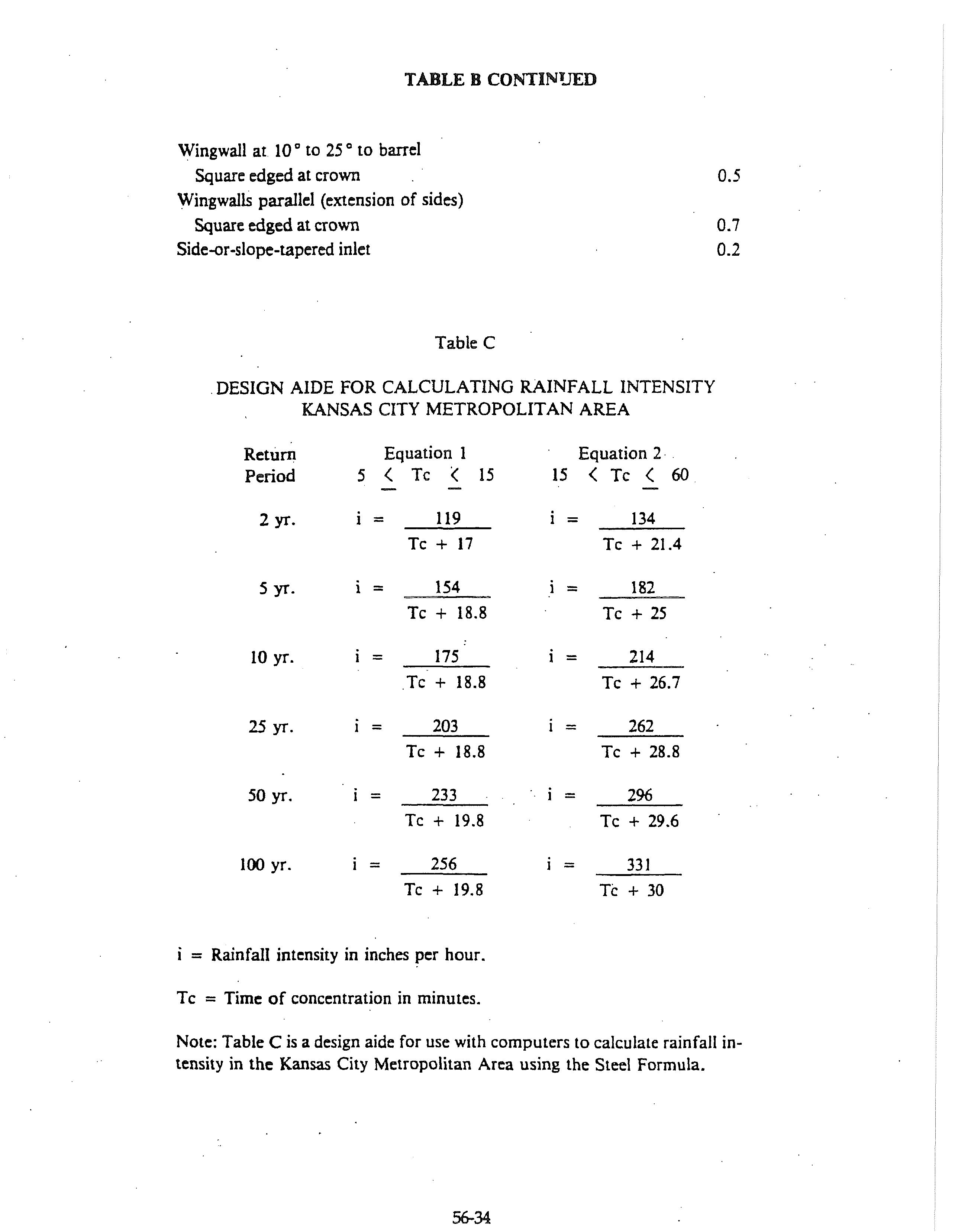
5602.5 Rainfall Intensity: Rainfall intensity shall be determined from Figure 1 or Table C using a Calculated Time of Concentration, TC· Tc is equal to the overland flow time to the most upstream inlet or other point of entry to the system, Inlet Time, Ti plus the time for flow in the system to travel to the point under consideration Travel Time, Ty. (Tc = TJ .+ Ty).
A. Inlet Time: TJ shall be u1lculatcd by the following formula or determined graphically fmm Figure 2, but shall not be less than 5.0 minutes nor greater than 15.0 minutes:
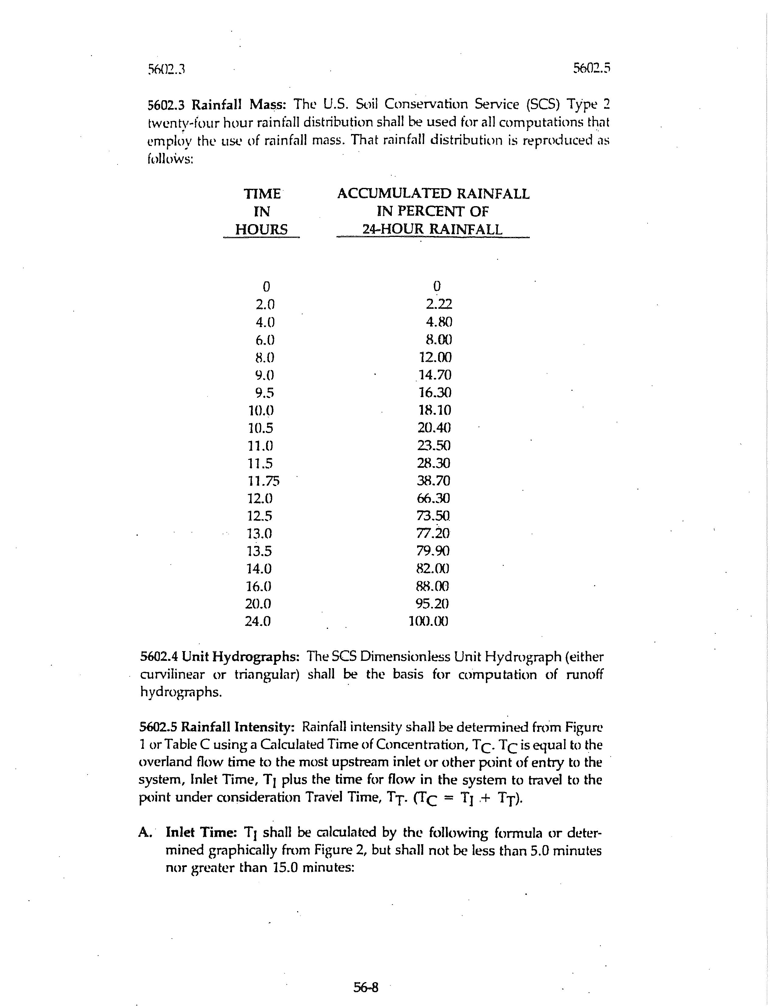
Ti = 1.8 (1.1 - q D Ill where:
T1 = Inlet TIIne in minutes.
C = Rational Method Runoff Coefficient as determined in accordance with paragraph 5602.2
D = Overland flow distance parallel to slope in feet (300-feet shall be the maximum distance used for overland flow )
S = Slope of tributary area surlace perpendicular to contour in pen:ent.
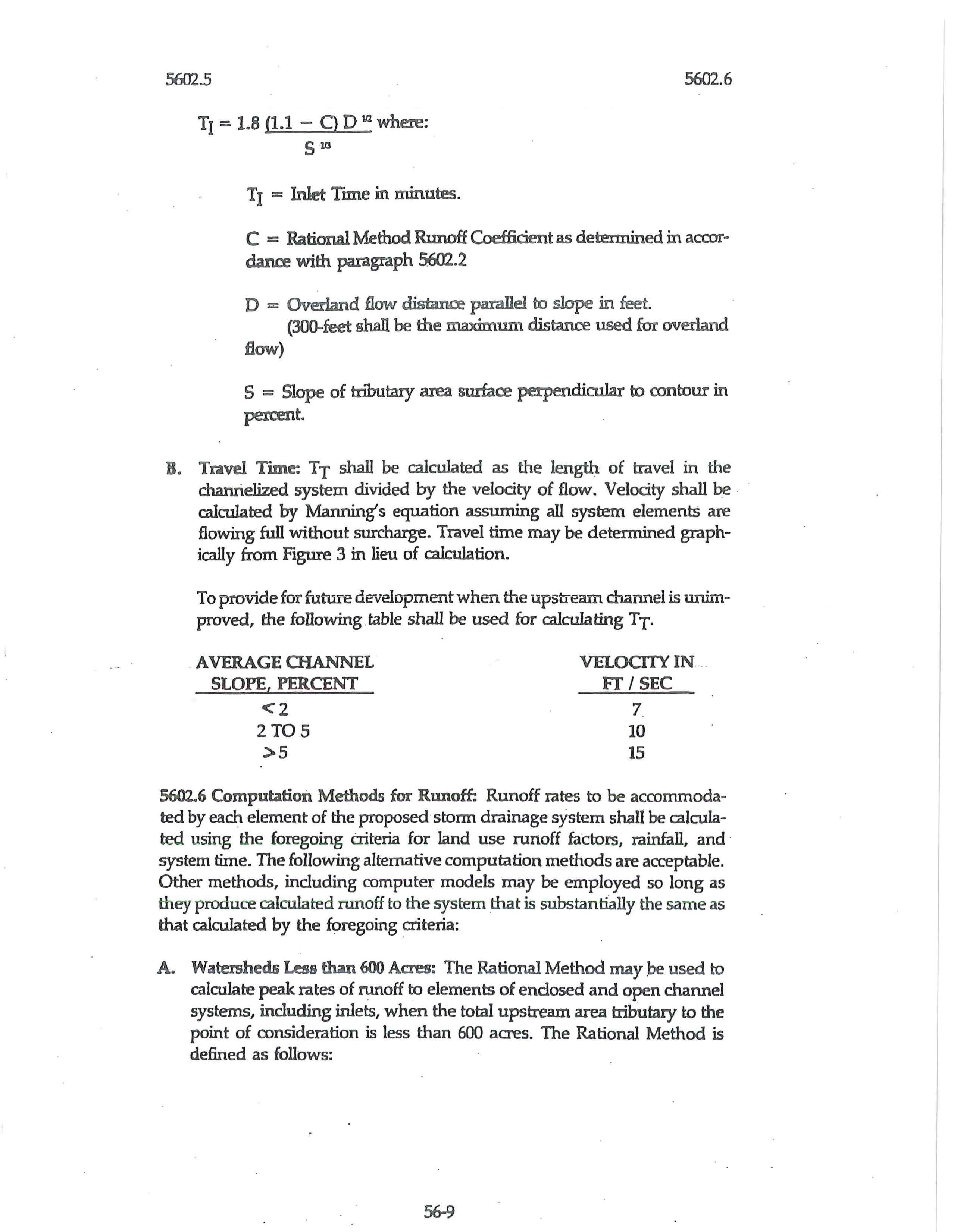
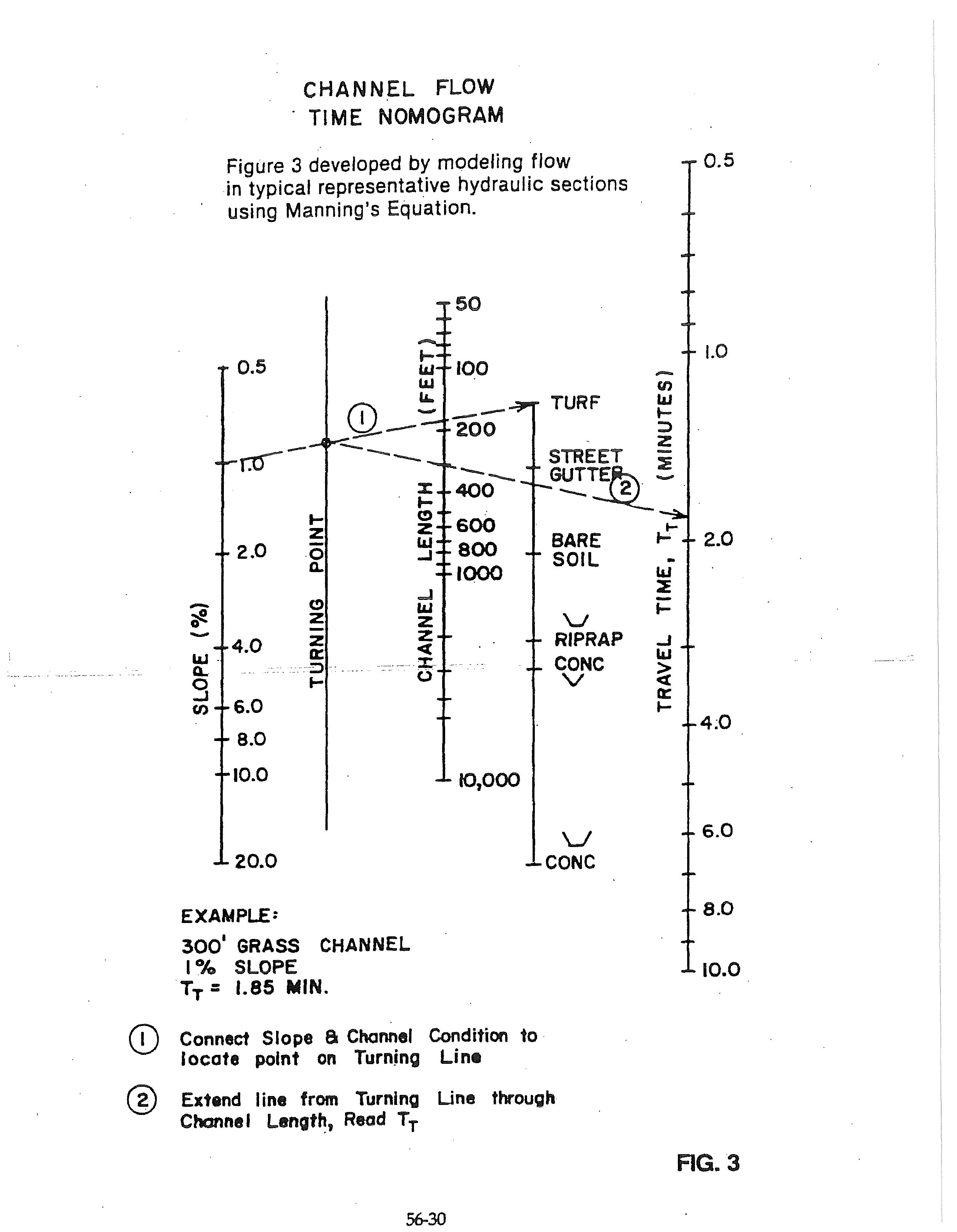
B. Travel Tmte: TT shall be calrulated as the length of travel in the chanrielized system divided by the velocity of flow. Velocity shall be calculated by Manning's equation assuming all system elements are flowing full without surcharge. Travel time may be determined graphically from Figure 3 in lieu of calculation.
To provide for future development when the upstream channel is unimproved, the following table shall be used for calrula ting TT-
5602.6 Computation Methods for Runoff: Runoff rates to be accommodated by each element of the proposed ·storm drainage system shall be calculated using the foregoing criteria for land use runoff factors, rainfall, and · system time. The following alternative computation methods are acceptable. Other methods, including computer models may be employed so long as they produce calculated runoff to the system that is substantially the sam e as that calculated by the foregoing criteria:
A. Watersheds Less than 600 Acres: The Rational Meth od may .be used to calculate peak rates of runoff to elements of enclosed and open channel systems, including inlets, when the total upstream area tributary to the point of consideration is less than 600 acres. The Rational Method is defined as follows:
5602.6 5602.7
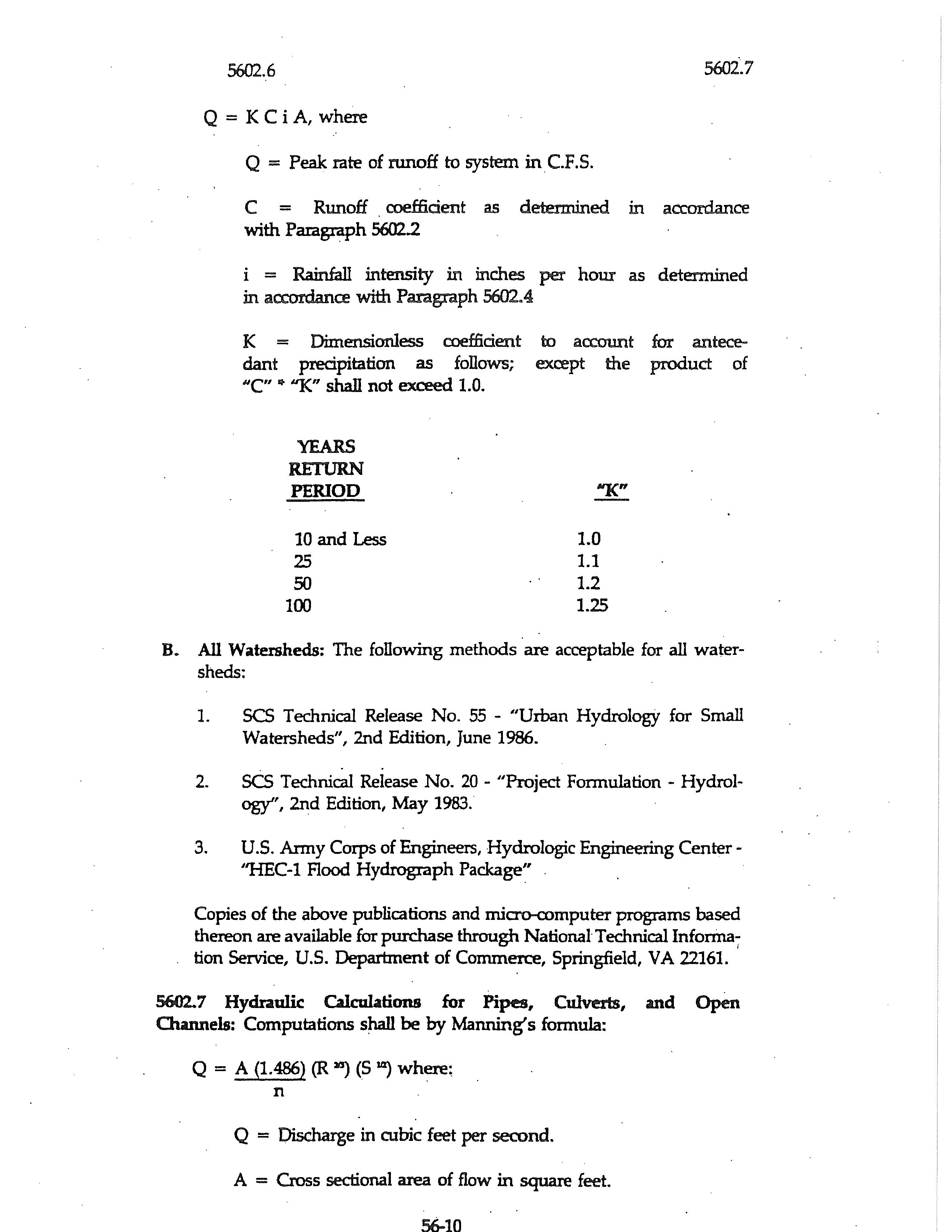
Q = K C i A, where
Q = Peak rate of runoff to system in C.F.S.
C = Runoff coefficient as determined in accordance with Paragraph 5602.2
i = Rainfall intensity in inches per hour as determined in accordance with Paragraph 5602.4
I< = Dimensionless coefficient to account for antecedant precipitation as follows; except the product of "'C" "''1<" shall not exceed 1.0.
B. All Watersheds: The following methods are acceptable for all watersheds:
1. SCS Technical Release No. 55 - "Urban Hydrology for Small Watersheds", 2nd Edition, June 1986.
2. SCS Technical Release No. 20 - "Project Formulation - Hydrology'', 2nd Edition, May 1983.
3. U.S. Army Corps of Engineers, Hydrologic Engineering Center"HEC-1 Flood Hydrograph Package"
Copies of the above publications and micro-romputer programs based thereon are available for purchase through National Technical Infonna-:tion Service, U.S. Department of Commerce, Springfield, VA 22161. ,
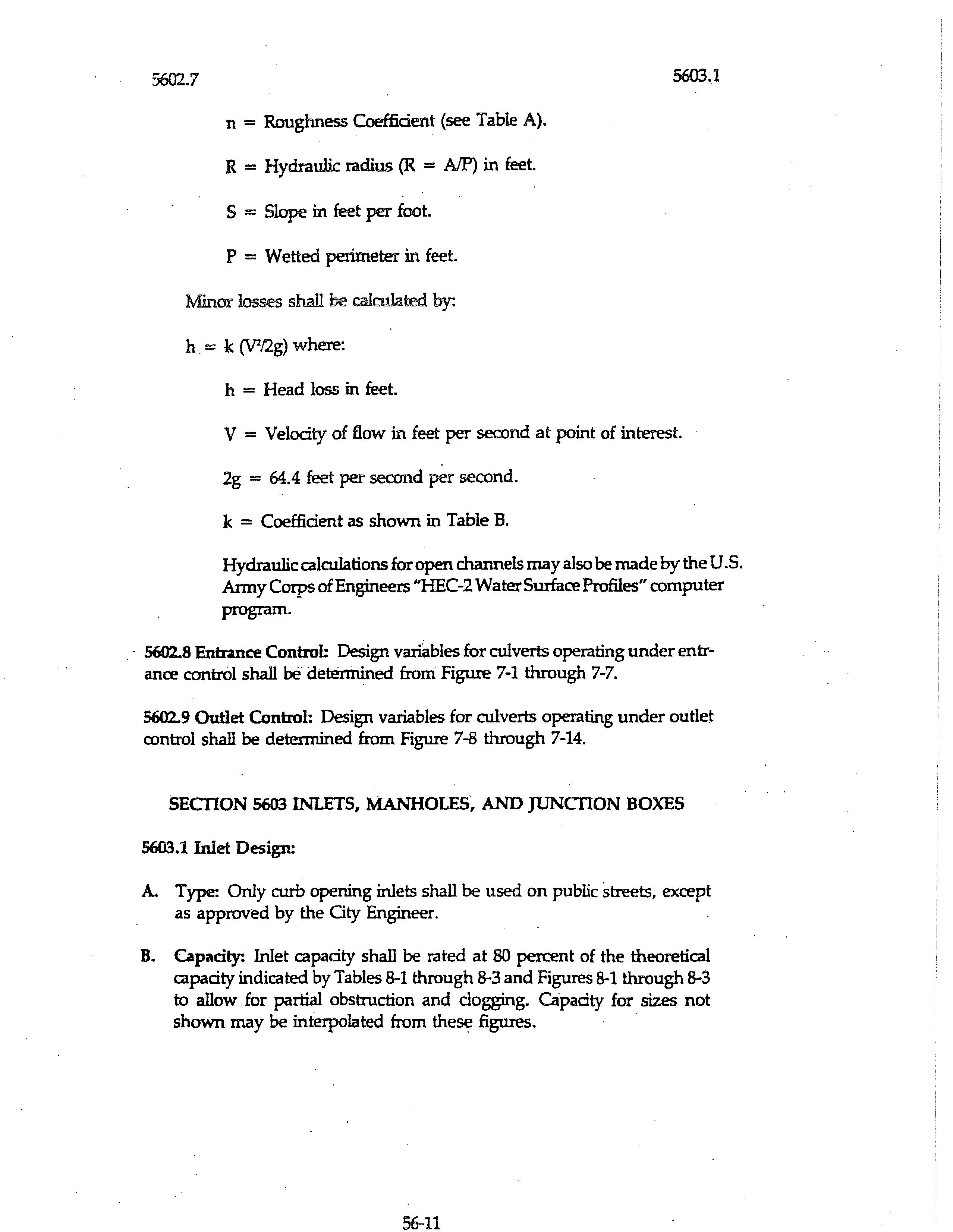
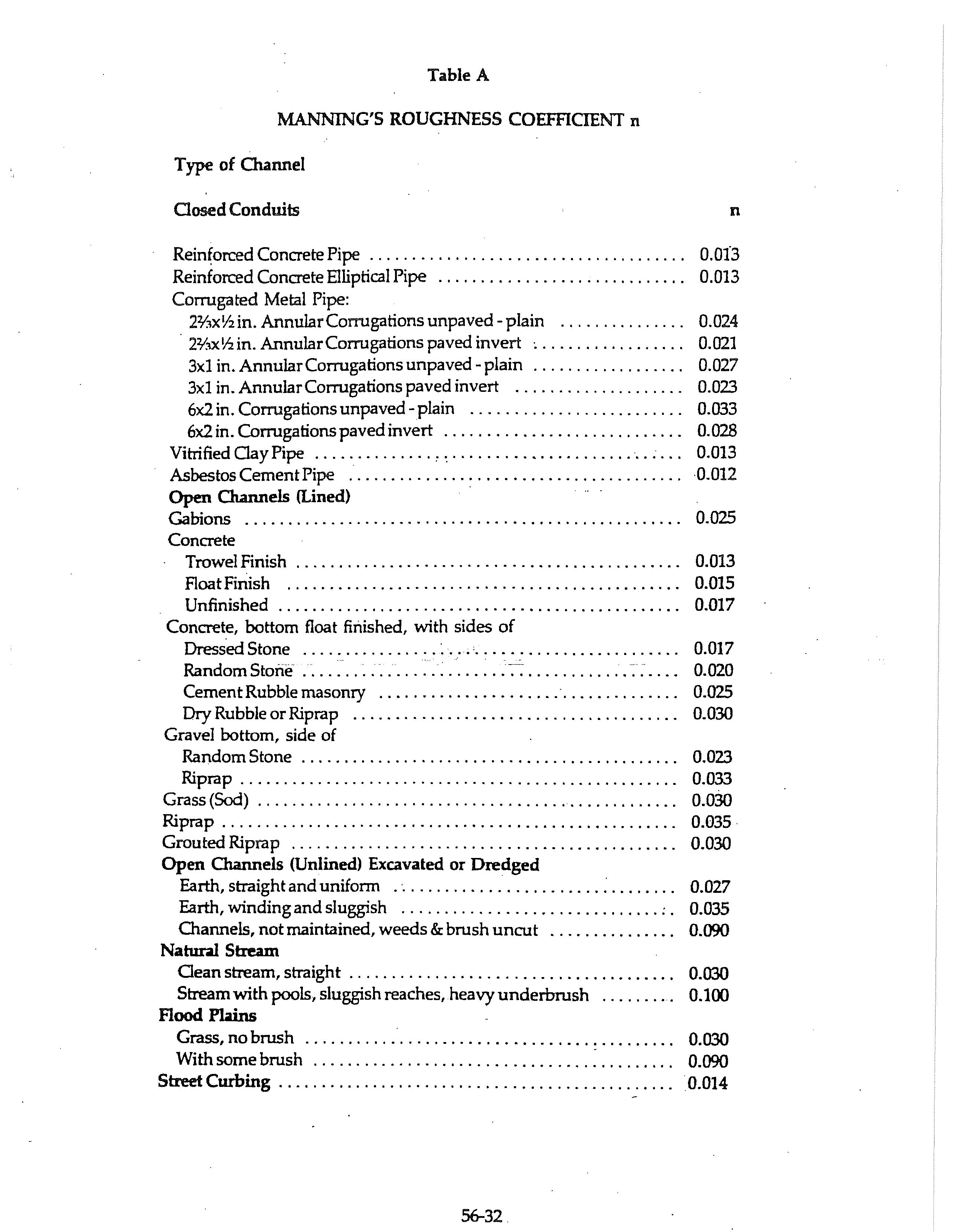
5602.7 Hydraulic CalcuLttions for Pipes, Culverts, and Open Owmels: Computations shall be by Manning's formula:
Q = A (1.486) (R 211) (S 14) where: n
Q = Discharge in cubic feet per second.
A = Cross sectional area of flow in square feet.
5602.7
n = Roughness Coefficient (see Table A).
R = Hydraulic radius (R = A/P) in feet.
S = Slope in feet per foot.
P = Wetted perimeter in feet.
Minor losses shall be calculated by:
h. = k (V1/2g) where:
h = Head loss in feet.
5603.1
V = Velocity of flow in feet per serond at point of interest.
2g = 64.4 feet per second per second.
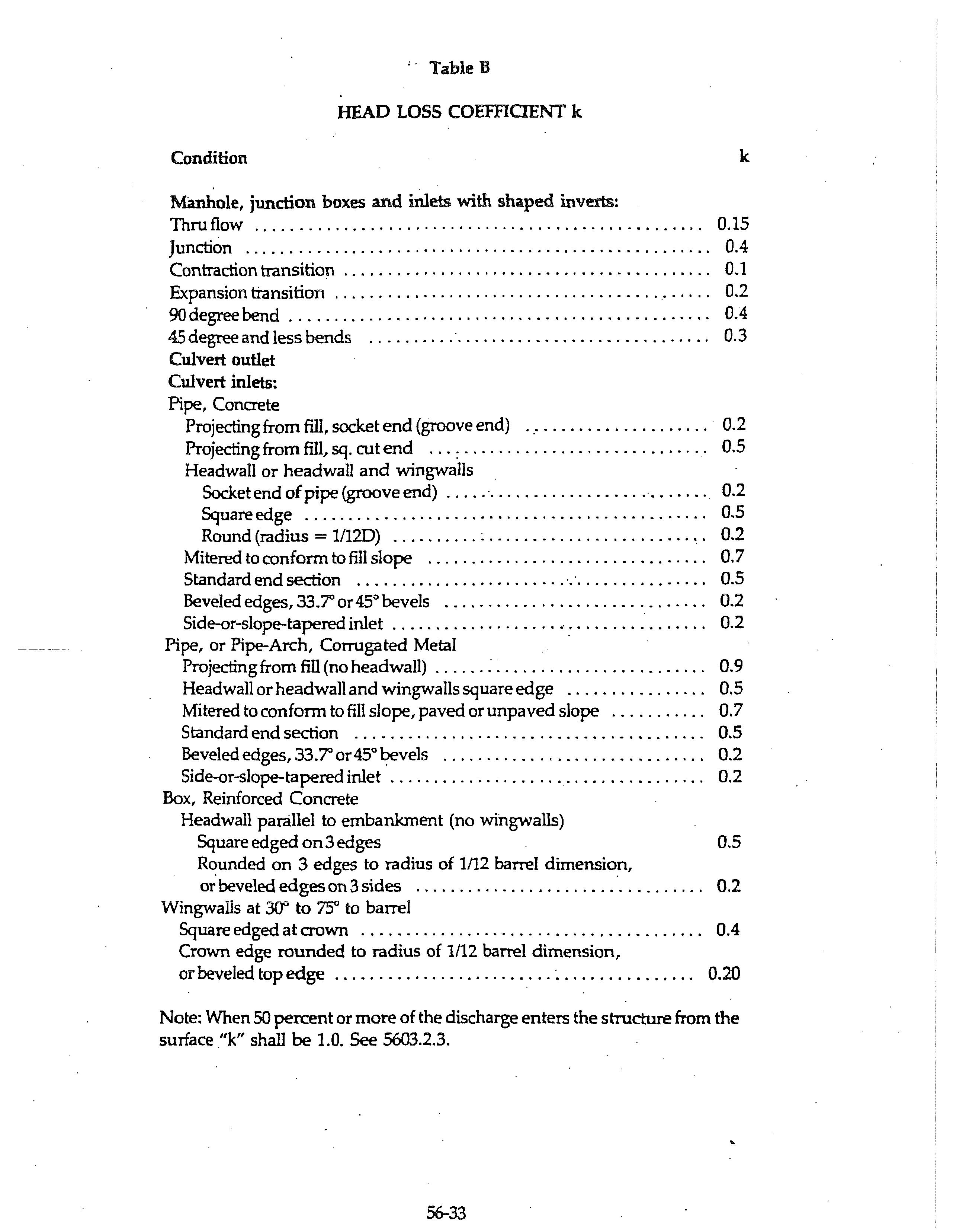
k = Coefficient as shown in Table B.
Hydraulic calculations for open channels may also be made by the U.S. Anny Corps of Engineers '1-IEC-2 Water Surface Profiles" computer program.
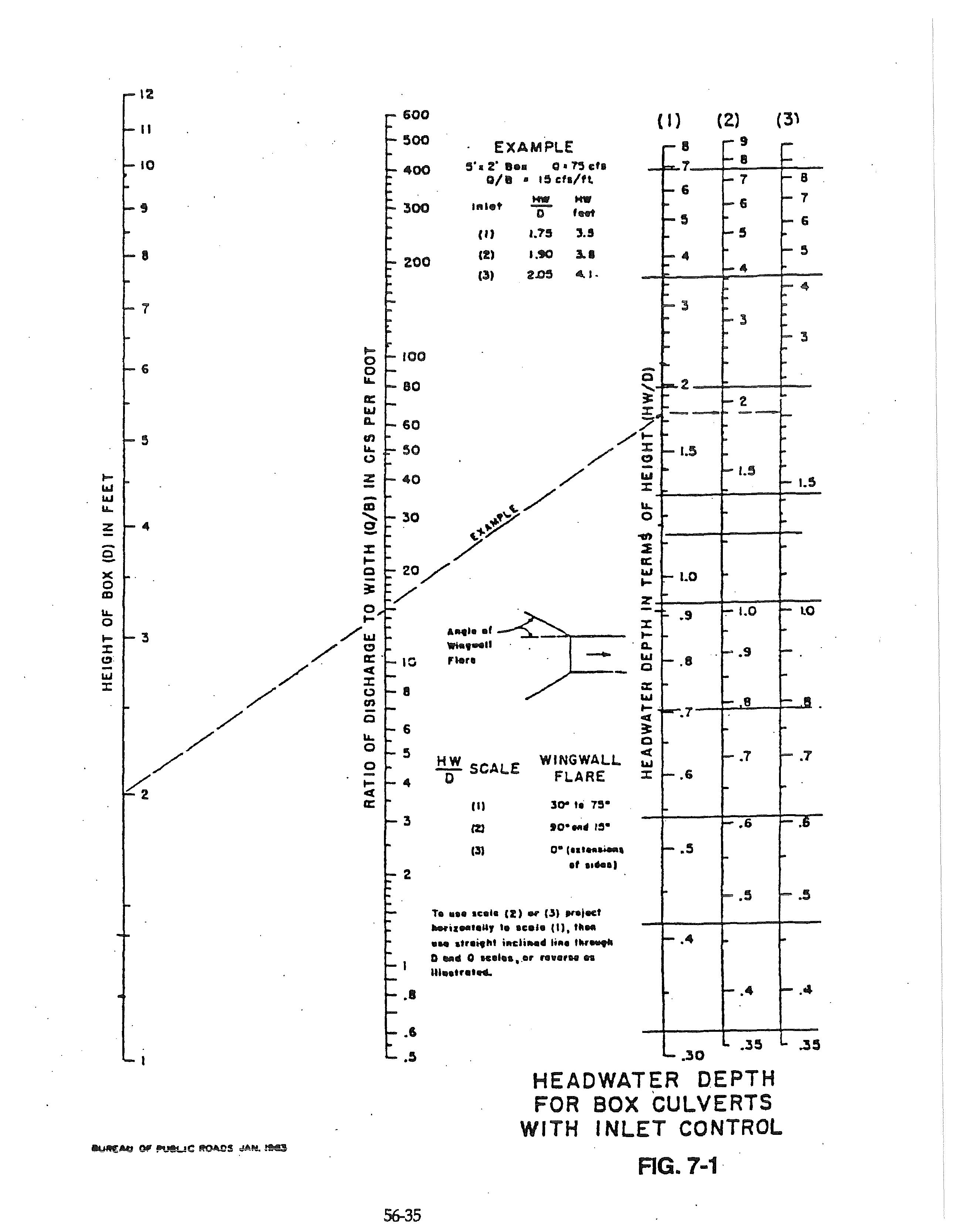
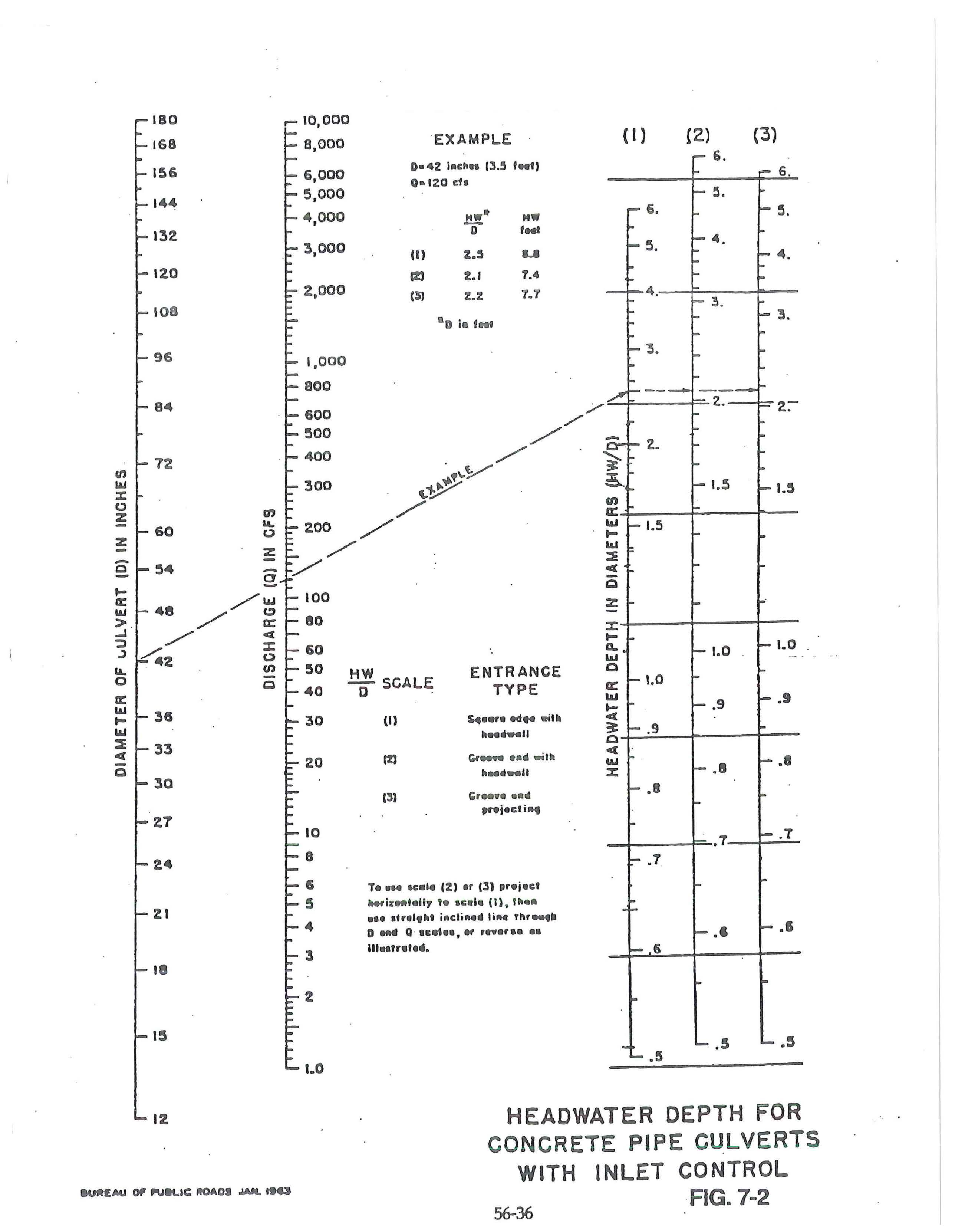
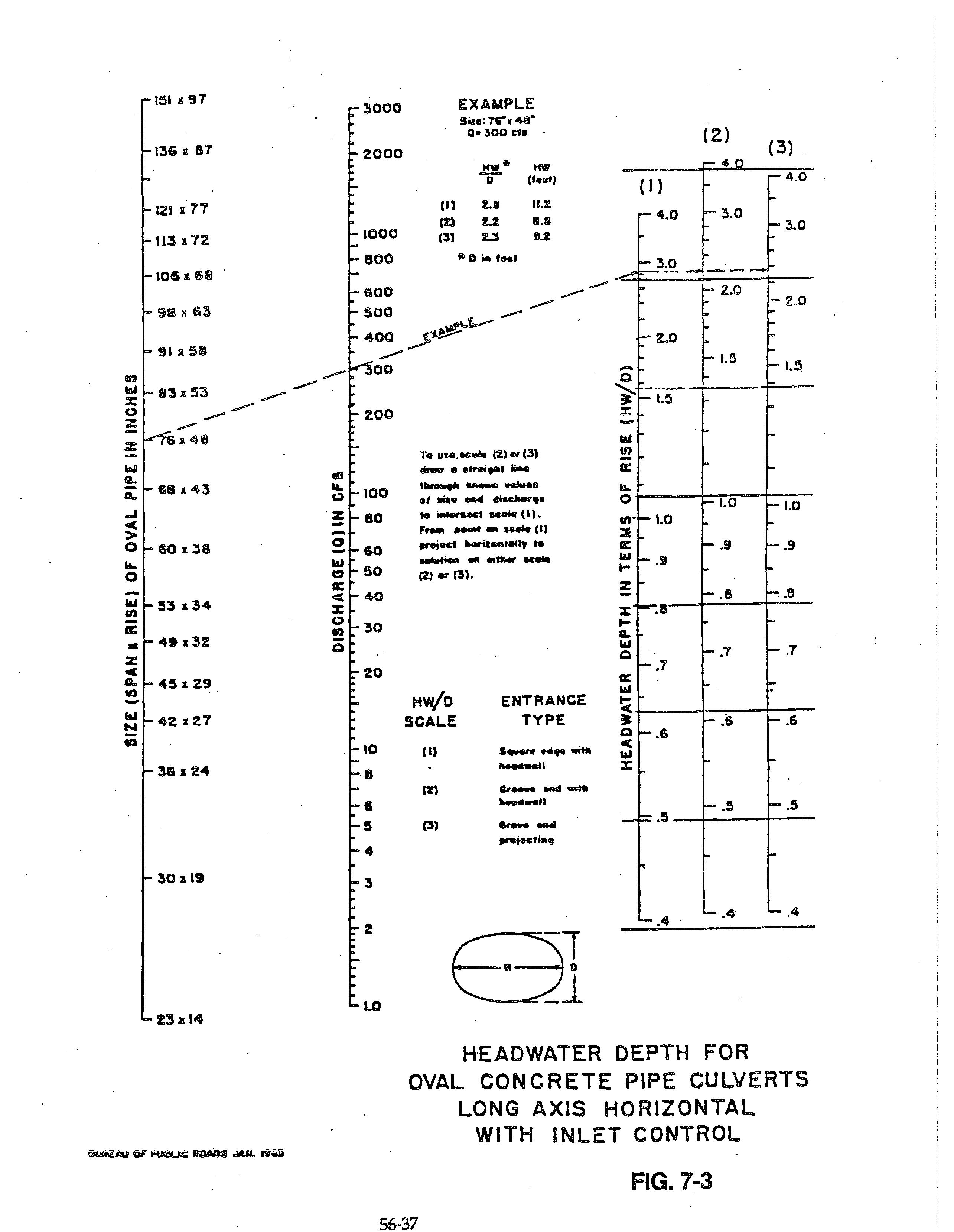
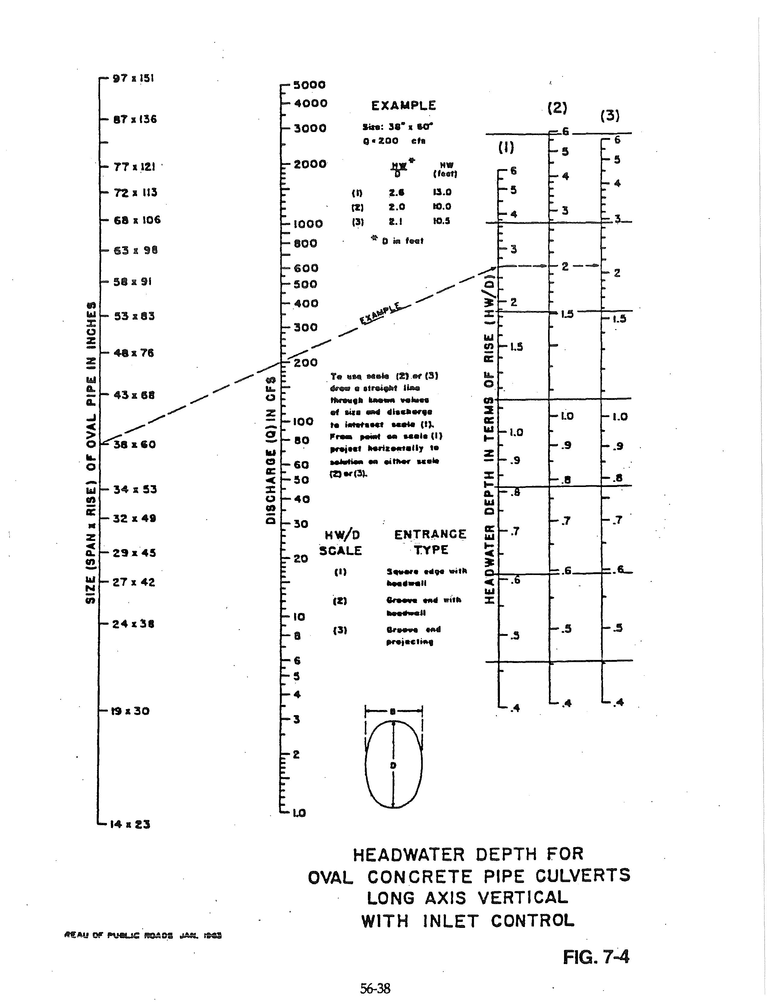
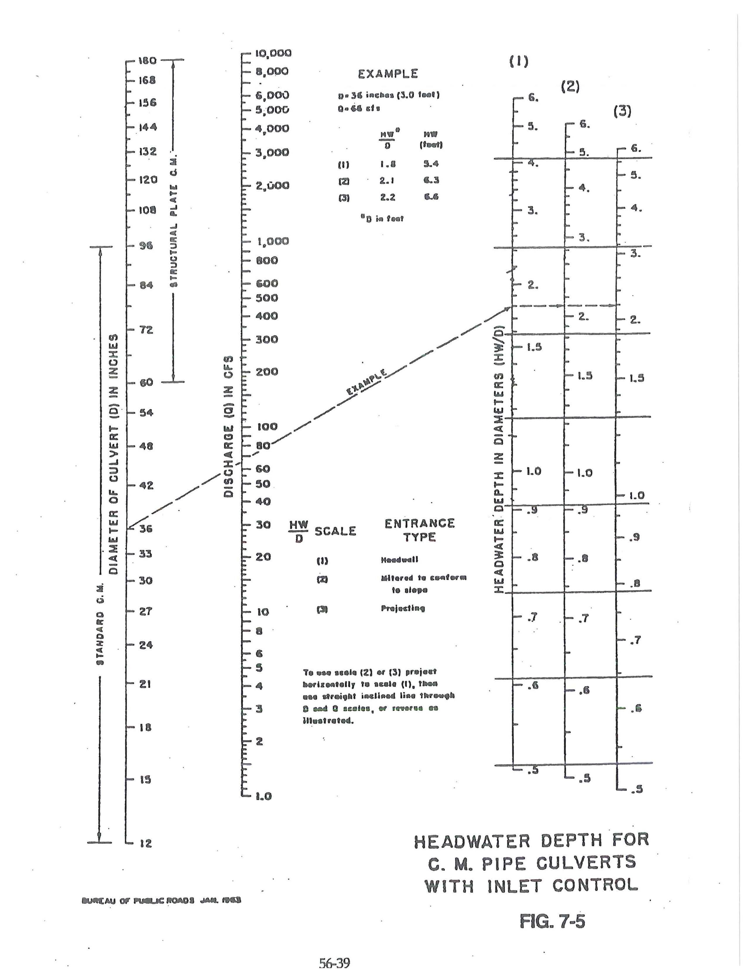
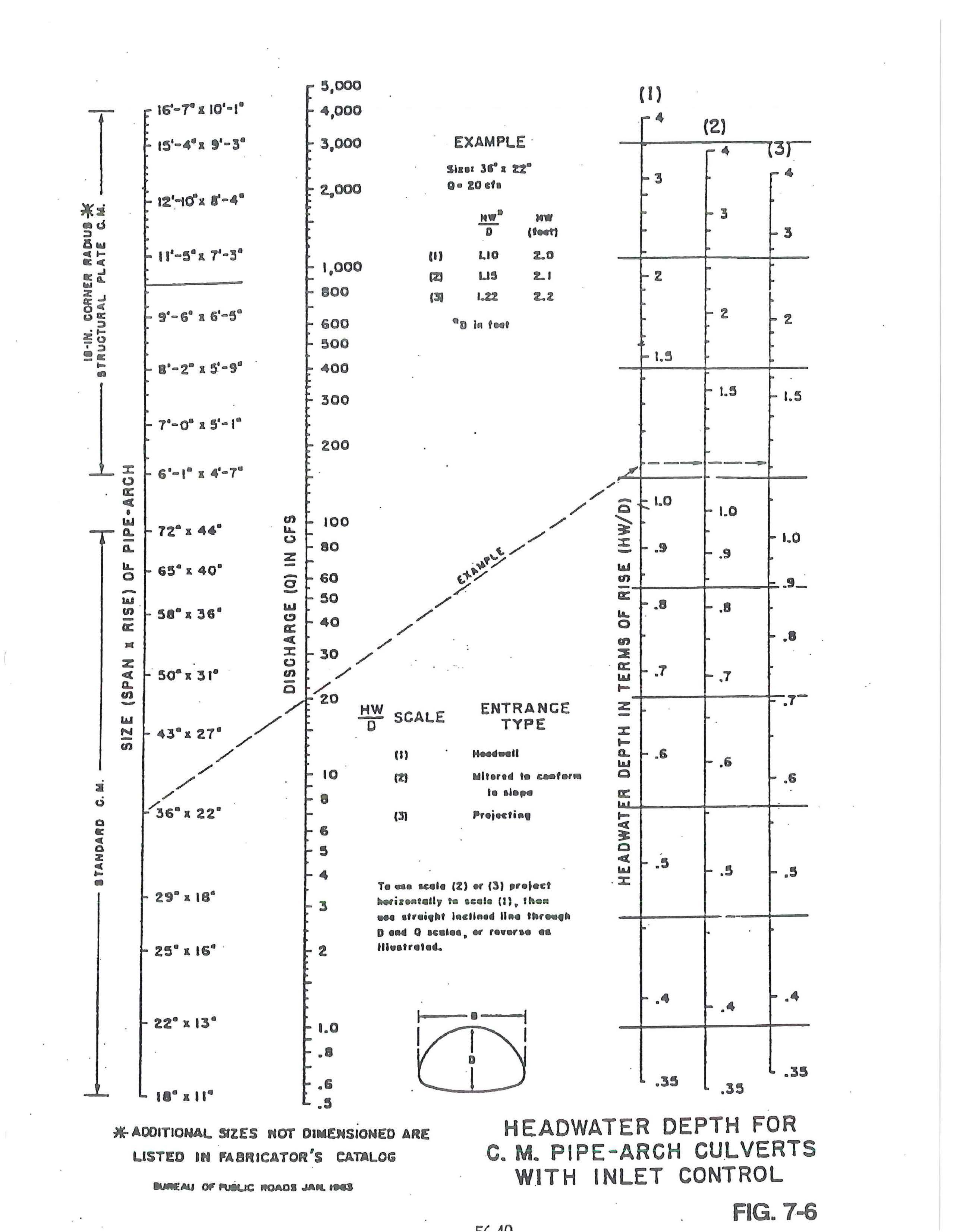
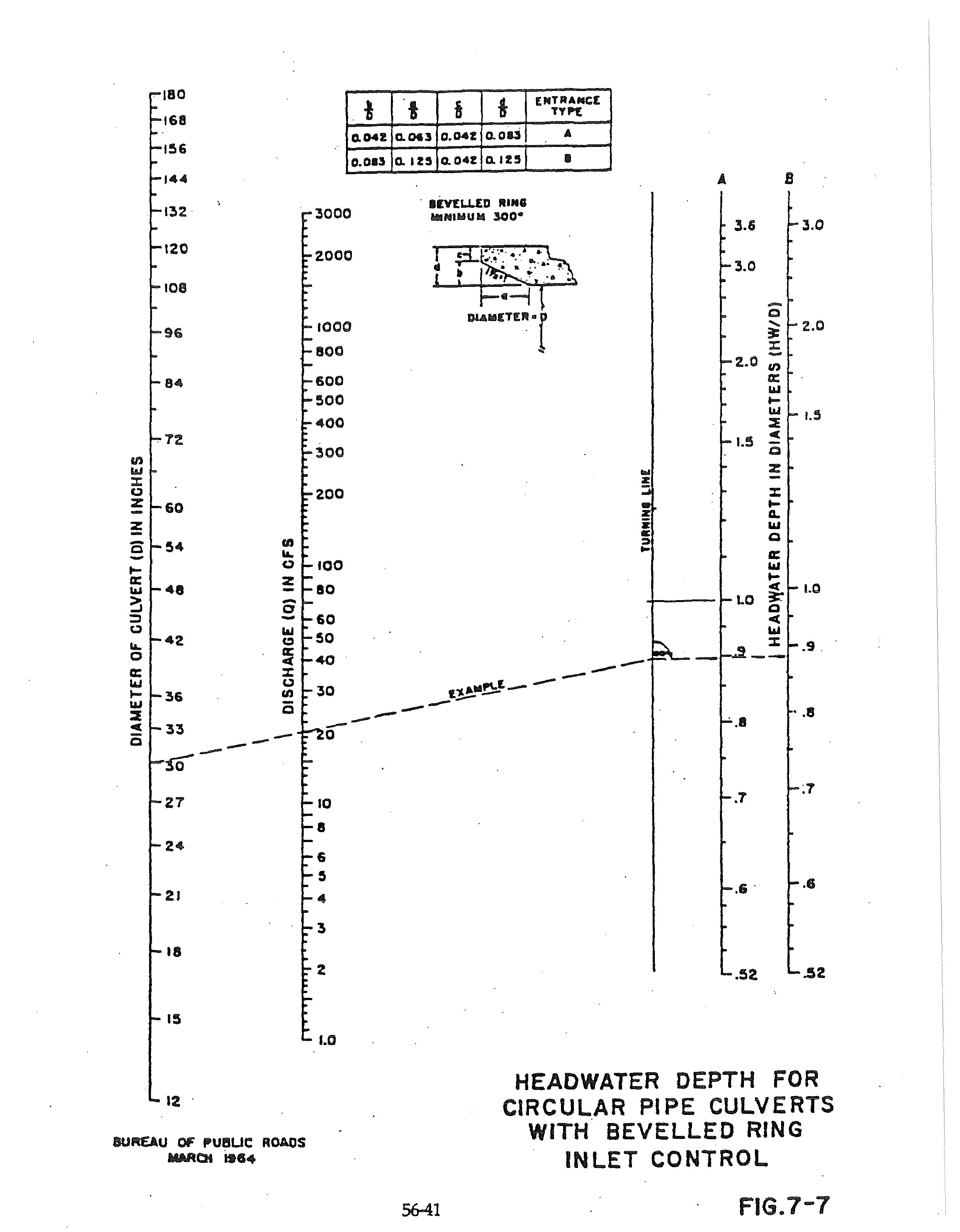
· 5602.8 Entrance Control: Design variables for culverts operating under entrance control shall be determined from Figure 7-1 through 7-7.
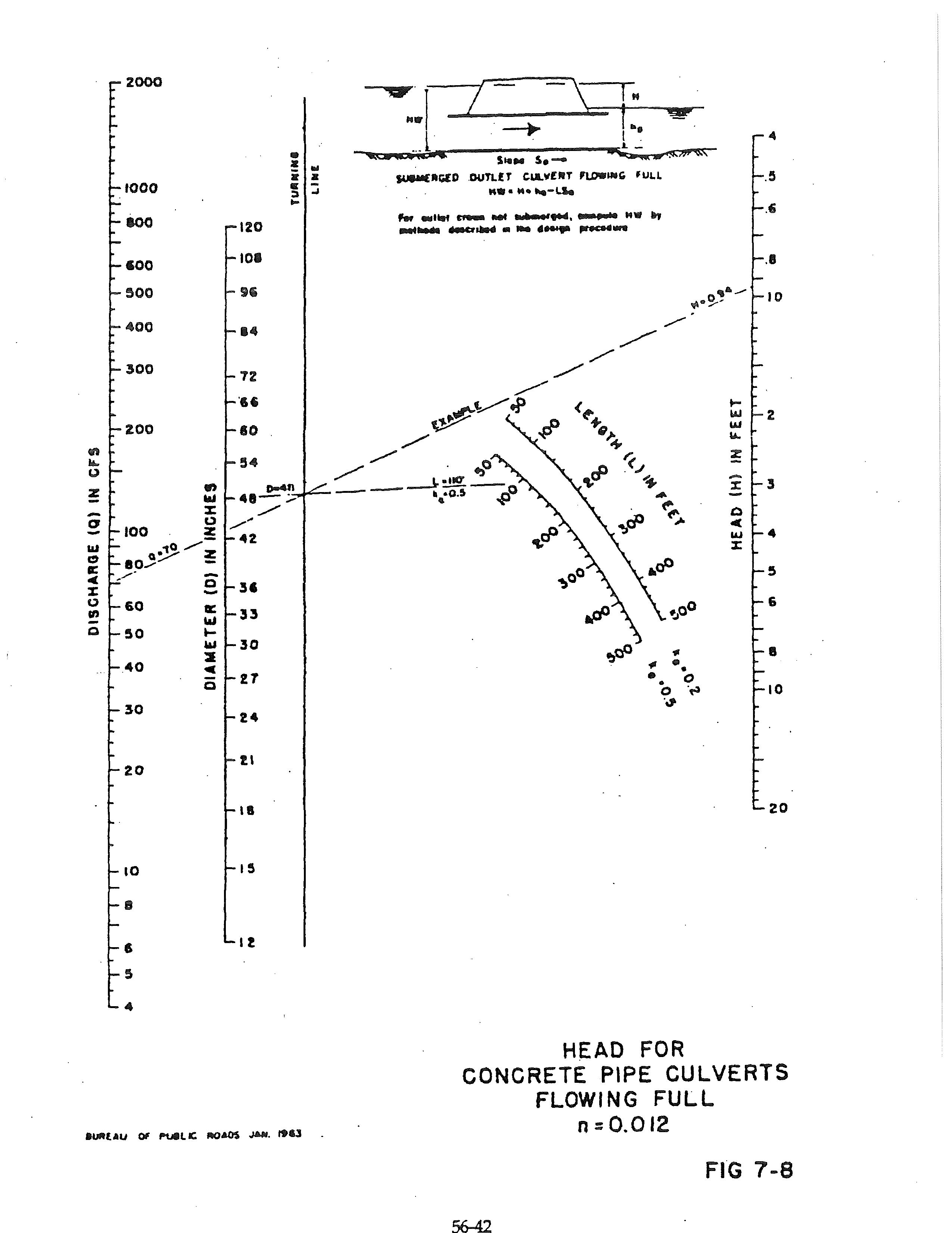
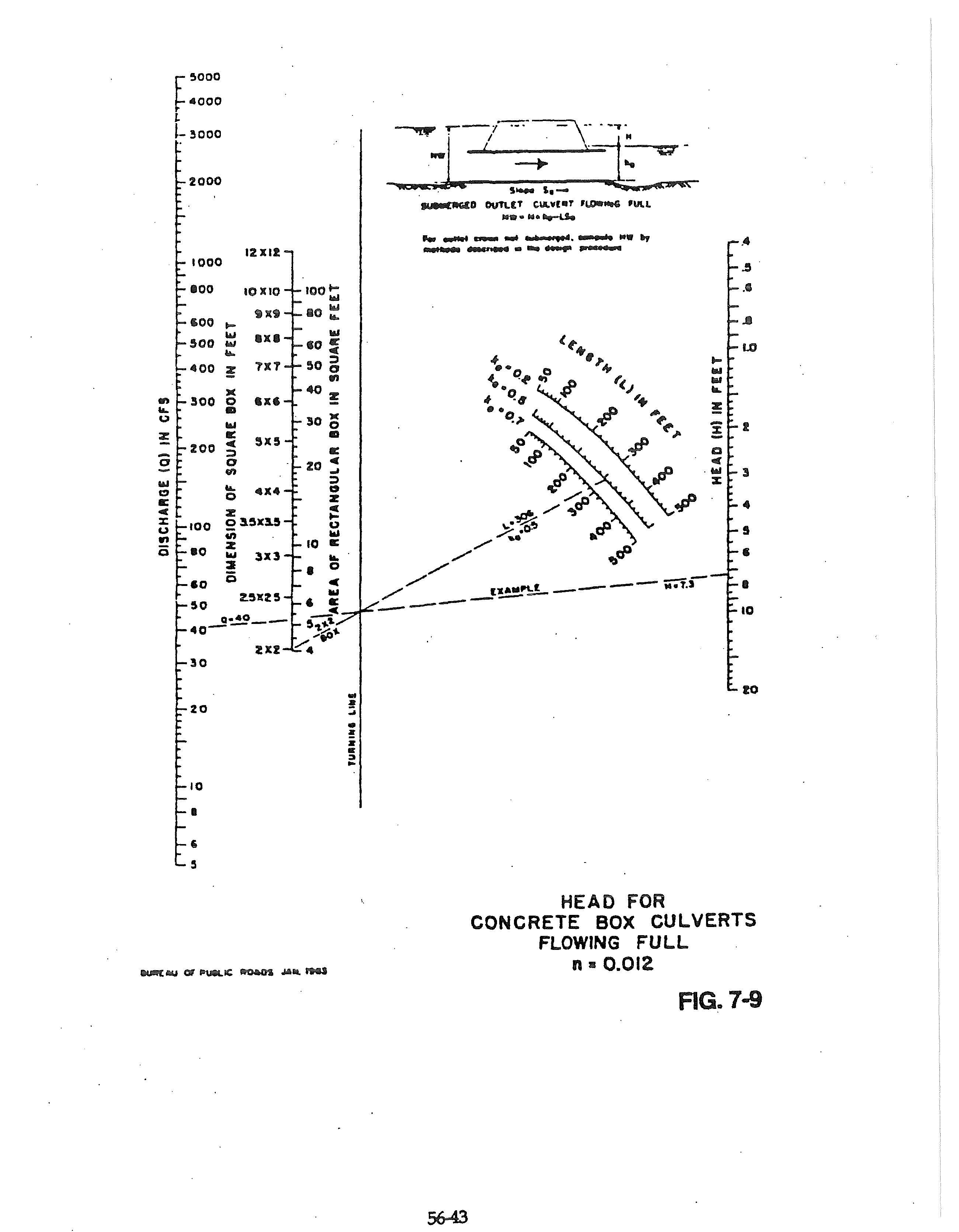
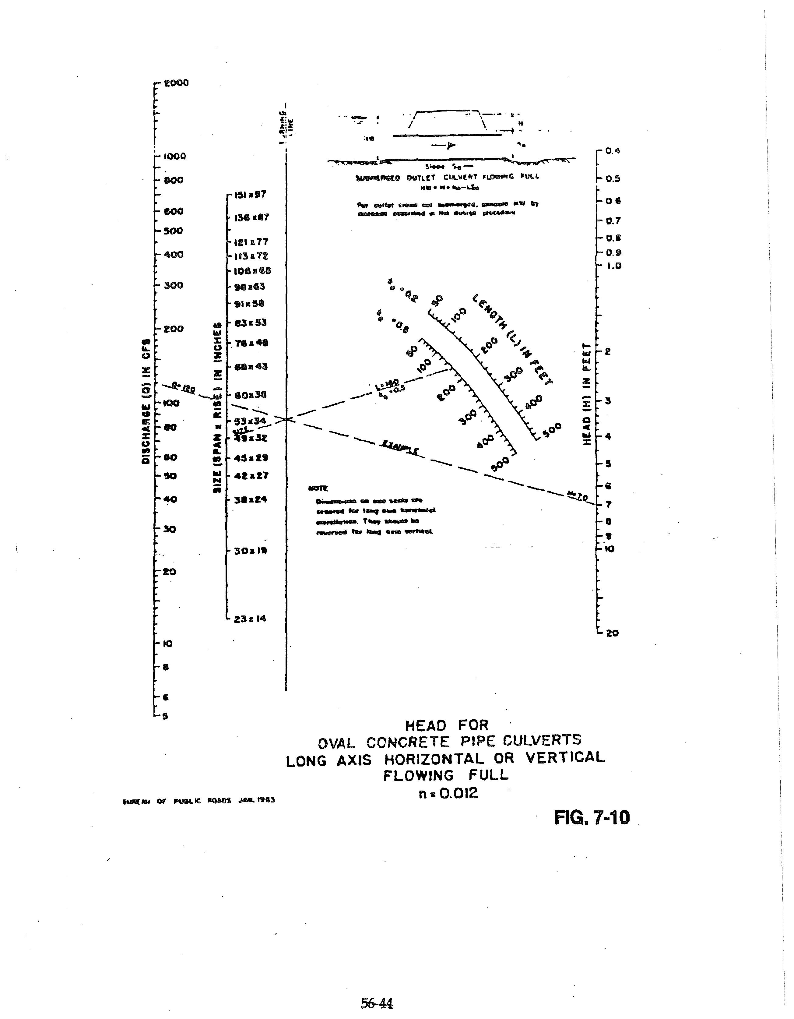
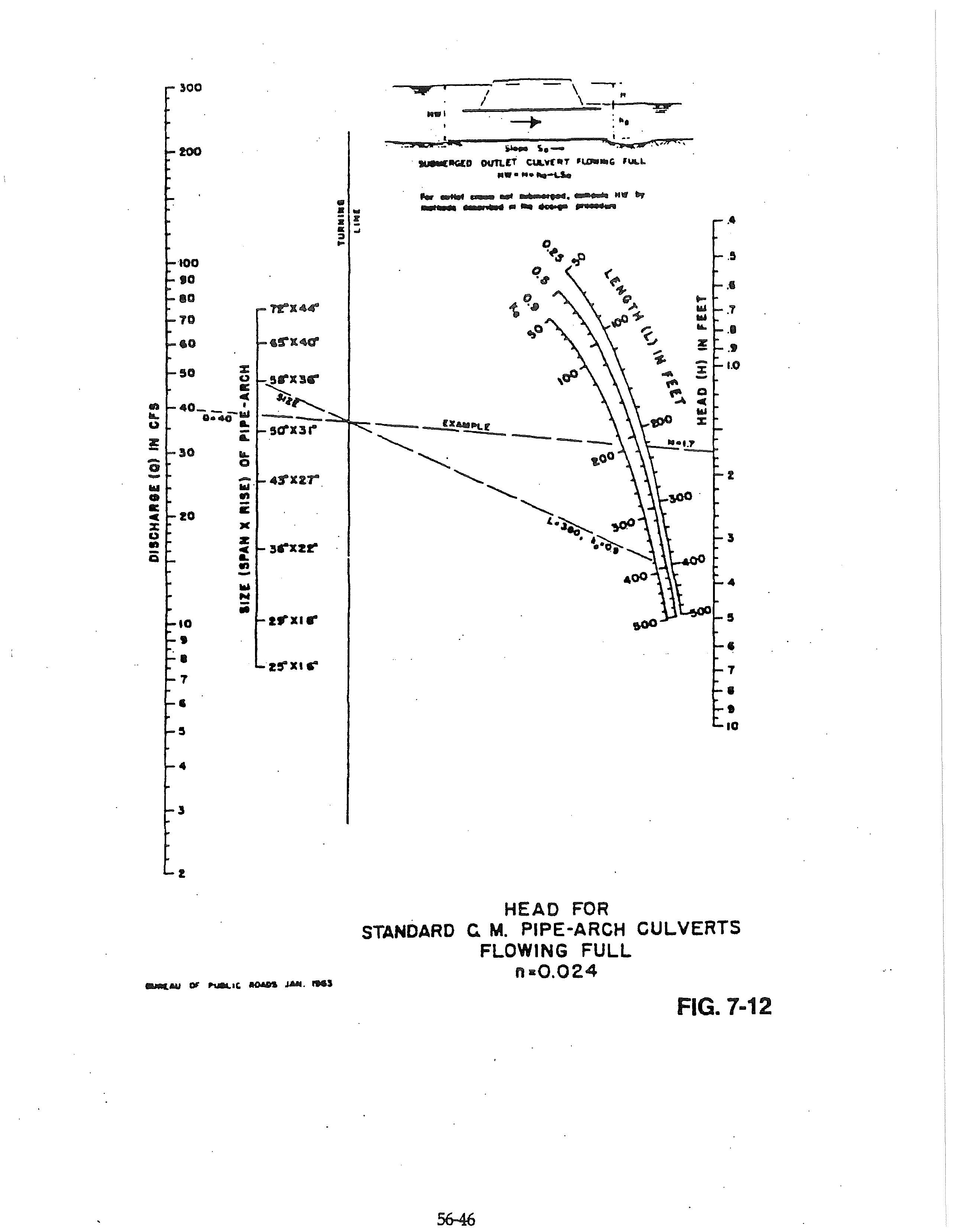
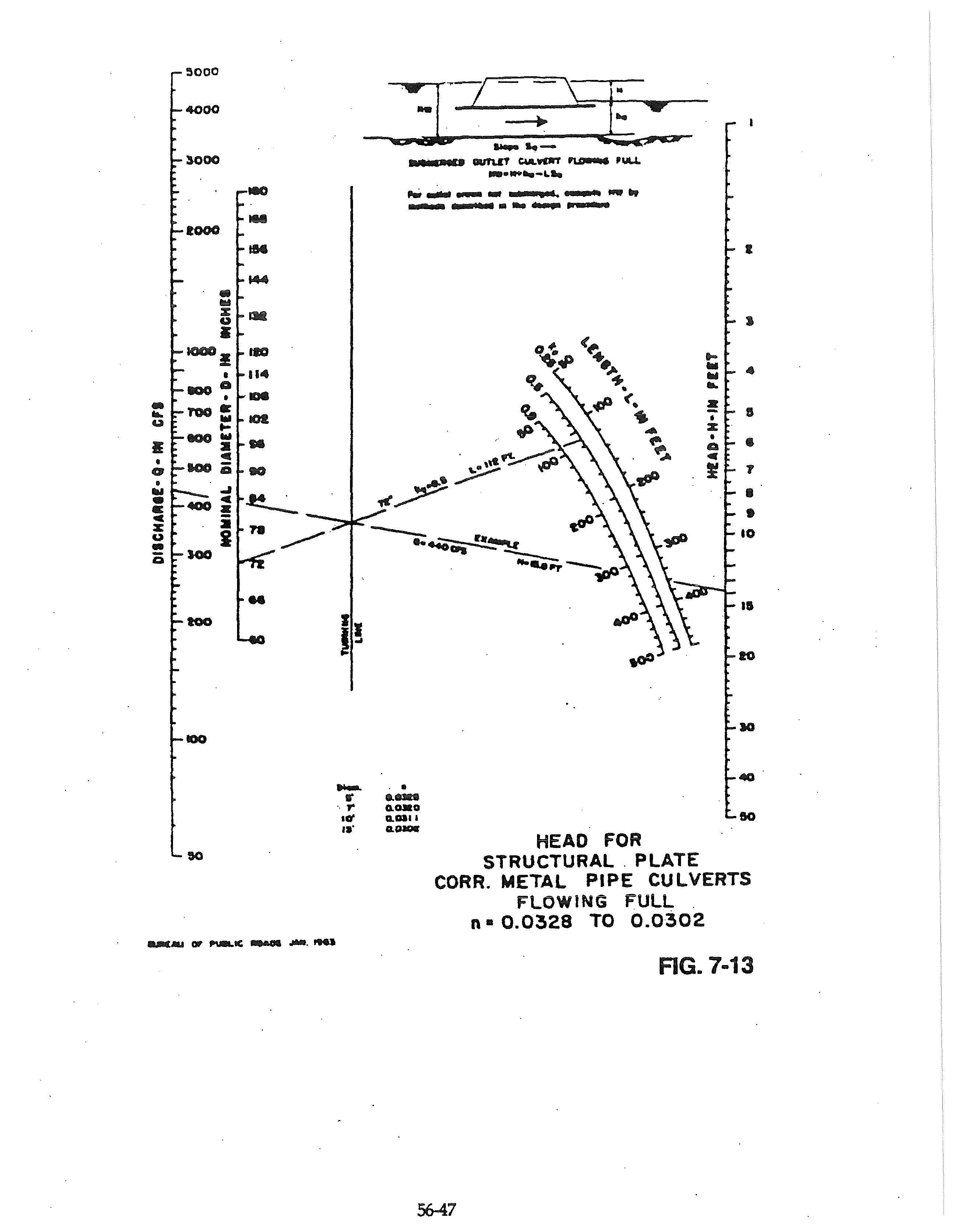
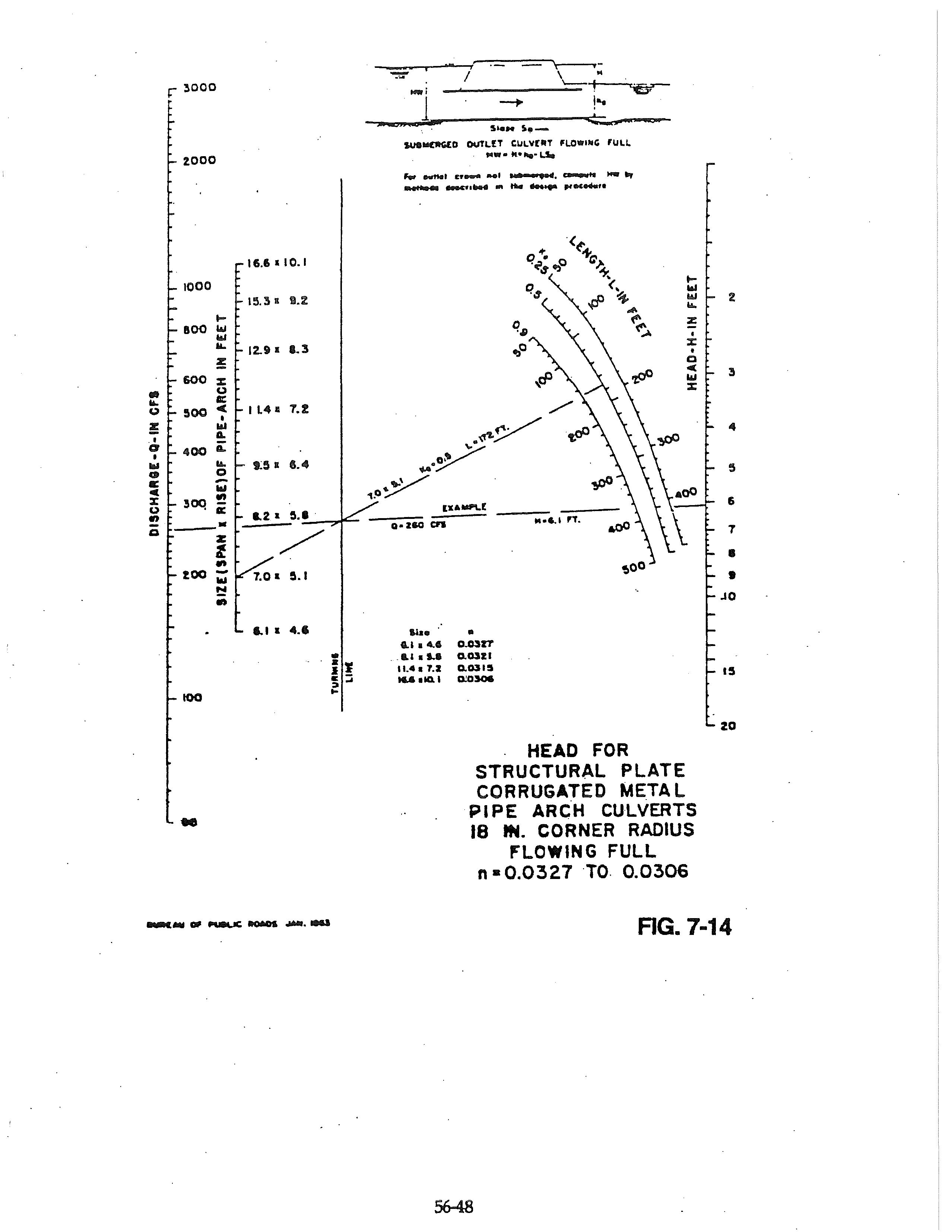
5602.9 Outlet Control: Design variables for culverts operating under outlet control shall be determined from Figure 7-8 through 7-14.
5603.1 Inlet Design:
A. Type: Only curb opening inlets shall be used on public streets, except as approved by the Oty Engineer.
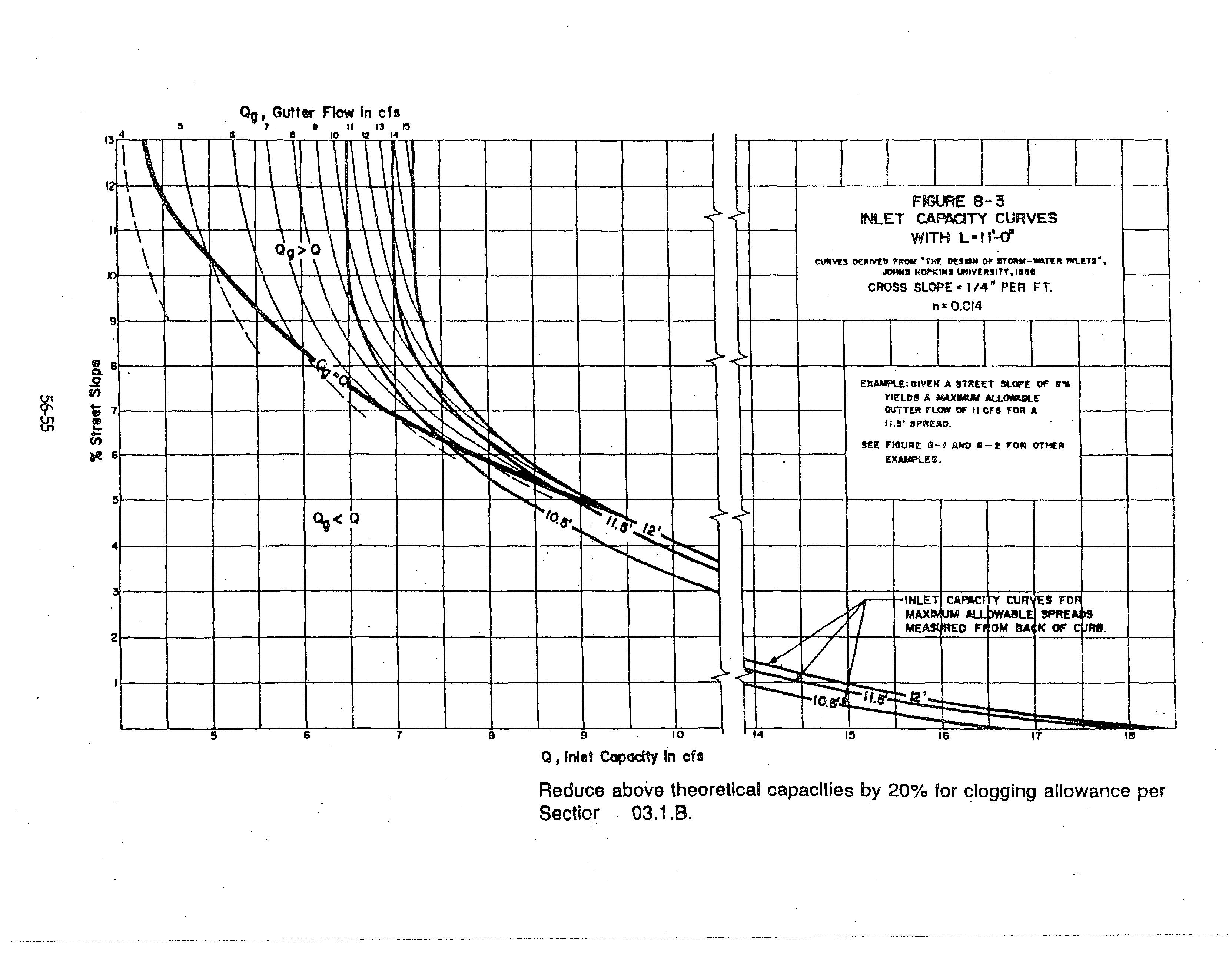
B. Capacity: Inlet capacity shall be rated at 80 percent of the theoretical capacity indicated by Tables 8-1 through 8-3 and Figures 8-1 through 8-3 to allow .for partial obstruction and clogging. Capacity for sizes not shown may be interpolated from the~ figures. ·
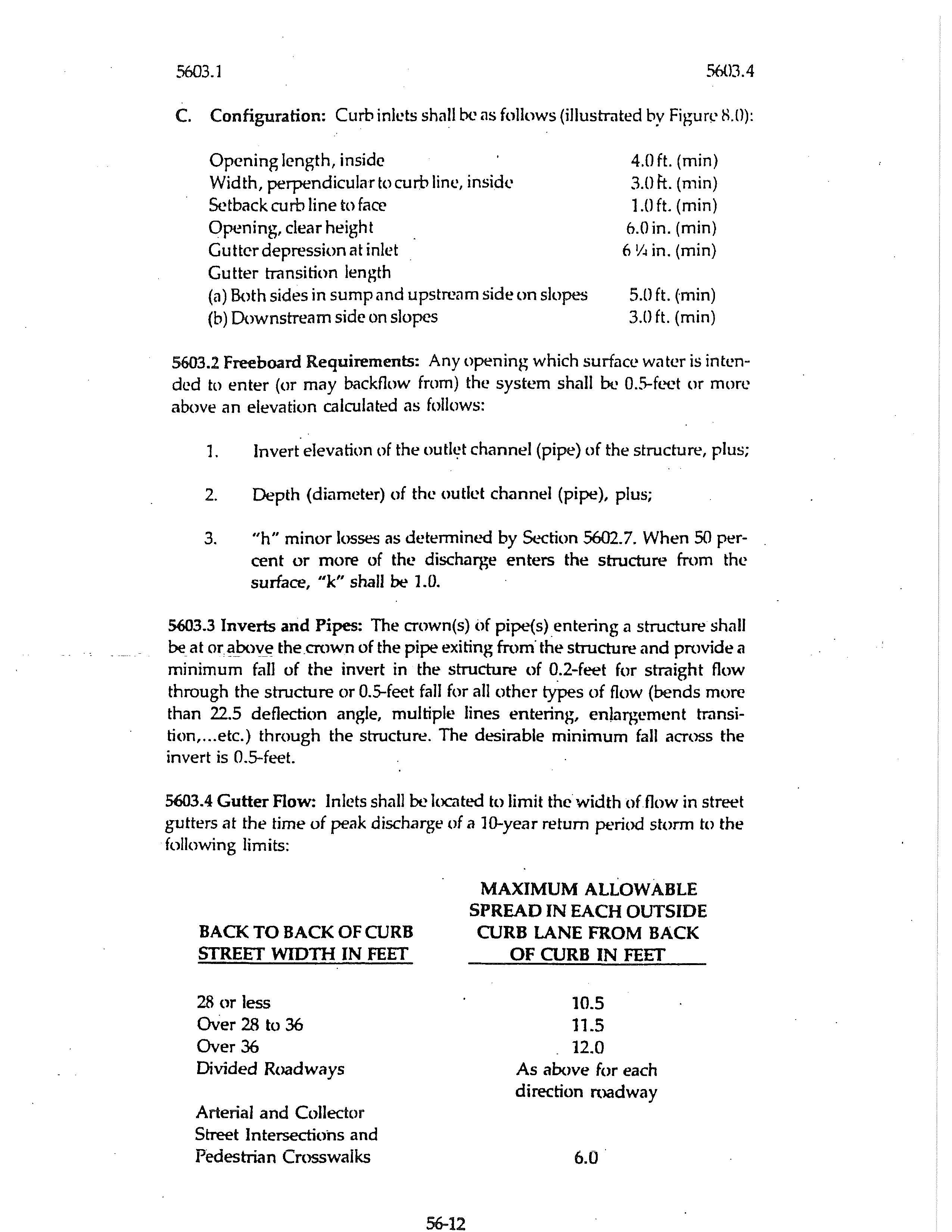
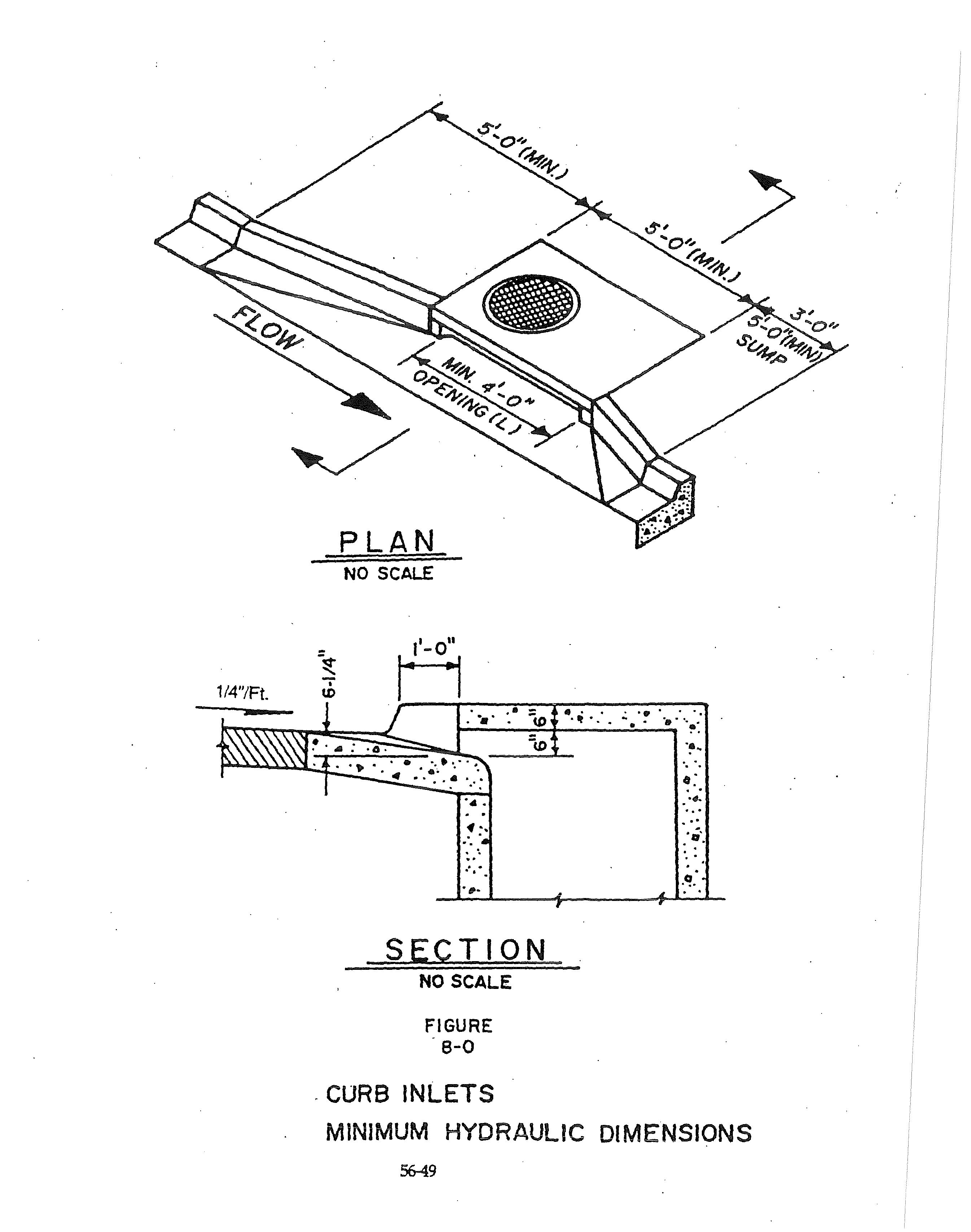
C. Configuration: Curb inlets shall be as follows (illustrated by Figun.' 8.0):
Opening length, inside Width, perpendicular to curb line, insid<.•
curb line to face
(a) Both sides in sump and upstrcc1m side on slopes
(b) Downstream side on slopes
5603.2 Freeboard Requirements: Any opening which surface wc1tcr is intended to enter (or may backflow from) the system shaJI be 0.5-foet or more above an elevation calculated as follows:
1. Invert elevation of the outlt;t channel (pipe) of the structure, plus;
2. Depth (diameter) of the outlet channel (pipe), plus;
3. "h" minor losses as determint.'CI by Section 5602.7. When 50 percent or more of the discharge enters the structure from the surface, "k'' shall be 1.0.
5603.3 Inverts and Pipes: The crown(s) <>f pipe{s) _entering a structure shall be at or.?J:>ov_e the crown of the pipe exiting from· the structure and provide a minimum fall of the invert in the structure of 0.2-feet for straight flow through the structure or 0.5-feet fall for all other types of flow (bends more than 22.5 deflection angle, multiple lines entering, enlargement transition, ... etc.) through the structure. The desirable minimum fall across the invert is 0.5-feet.
5613.4 Gutter Aow: Inlets shall be located to limit the width of flow in street gutters at the time of peak discharge of a JO-year return period storm to the following limits:
As above for each direction roadway
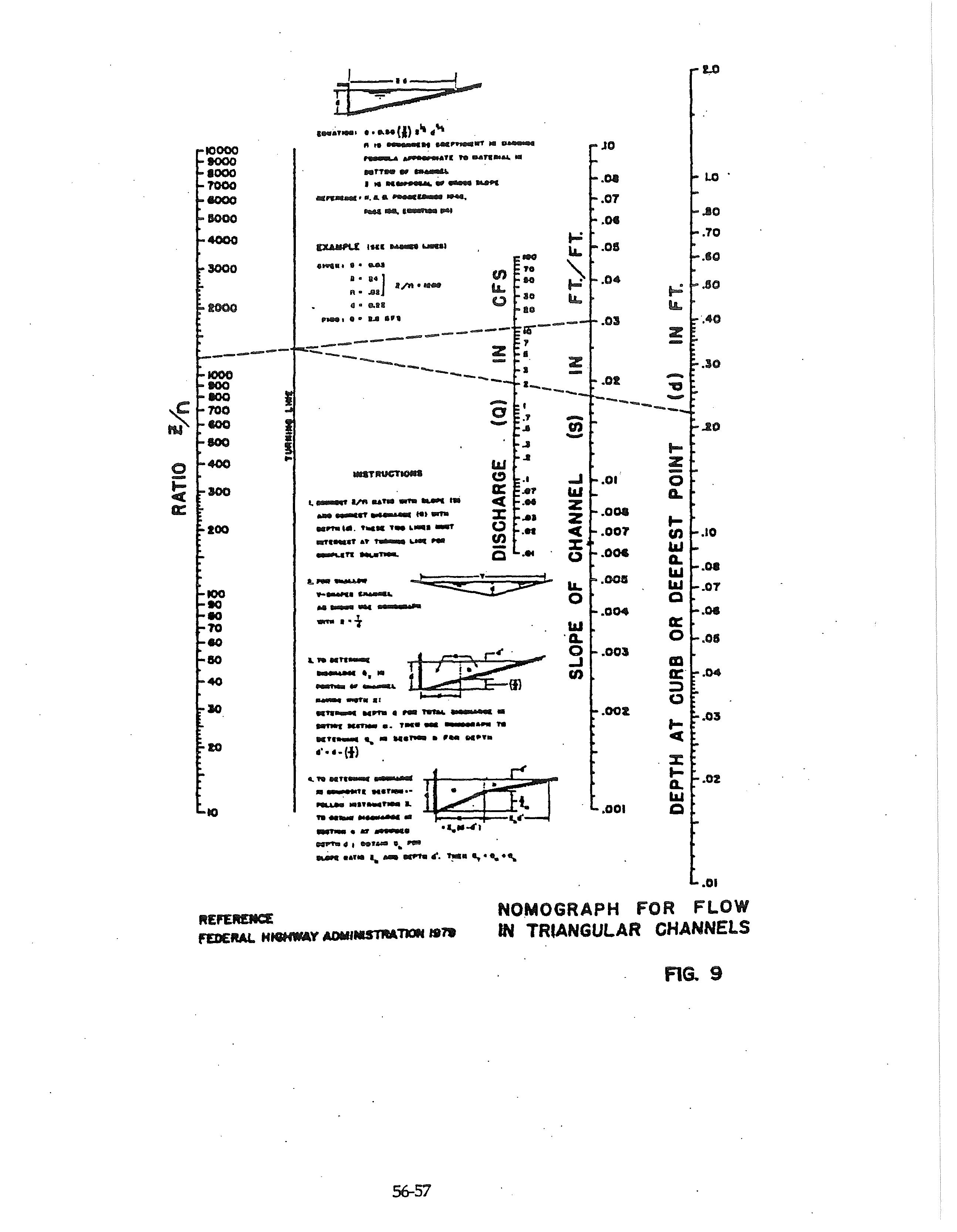
5603.5 Gutter Cipacity. Izzard' s Formula or Figure 9 shall be used to determine gutter flow:
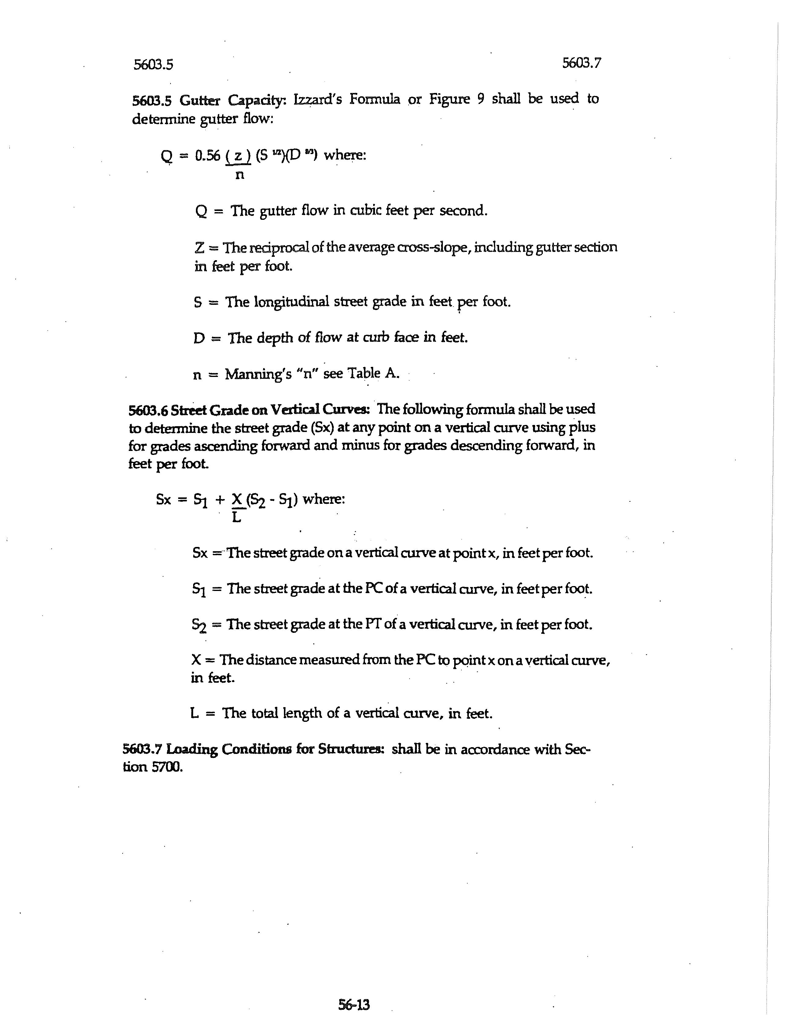
Q = 0.56 t!J (S L2){D lfl) where:
Q = The gutter flow in cubic feet per second.
Z = The reciprocal of the average cross-slope, including gutter section in feet per foot.
S = The longitudinal street grade in feet per foot.
D = The depth of flow at curb face in feet.
n = Manning's "n" see Table A.
5603.6 Street Grade on Vertiw Curves: The following formula shall be used to determine the street grade (Sx) at any point on a vertical curve using plus for grades ascending forward and minus for grades descending forward, in feet per foot
Sx = SJ. + ~(Si - SJ.) where:
Sx =-The street grade on a vertical curve at point x, in feet per foot.
SJ = The street grade at the PC of a vertical curve, in feet per foo_t.
Si = The street grade at the PT of a vertical curve, in feet per foot.
X = The distance measured from the PC to pc,int x on a vertical curve, in feet. .
L = The total length of a vertical curve, in feet.
5603.7 Loading Conditions for Strw::tures: shall be in aa:ordance with Section 5700.
SECTION 5604 ENCLOSED PIPE SYSTEMS:
5604.1 Easements: Permanent easements shall be dedicated to the Citv for operation and .maintenance of the storm drainage facilities. Easement width shall not be less than 15-feet, or the outside width of the pipe or conveyance structure plus 10-feet; whichever is greater. Easements shall be centered on the pipe.
A. Perm.anent: The City Engineer may .require wider easements when other utilities are located within the same easement and/or when the depth of cover is greater than 4-feet.
B. Temporaxy: Temporary construction easements of sufficient width to provide access for construction shall be acquired when the proposed work is located in areas developed prior to construction.
5604.2 Capacity: Capacity shall be based on either inlet or outlet control, whichever condition indicates the least capacity. Minimum design pipe size shall be 12-inch diameter.
5604.3 Surcharge: An enclosed system may be designed_ to operate with surcharge if the following conditions are met:
J. · The Hydraulic Grade Line (HGL) must be 0.5-feet below any openings to the ground or street at all locations.
2. Watertight joints capable of withstanding the internal surcharge pressure are used in the construction.
3. Appropriate energy loses for bends, transitions, manholes, inlets, and outlets, are used in computing the HGL.
4. Energy methods (Bernoulli's equation) must be used for the computations.
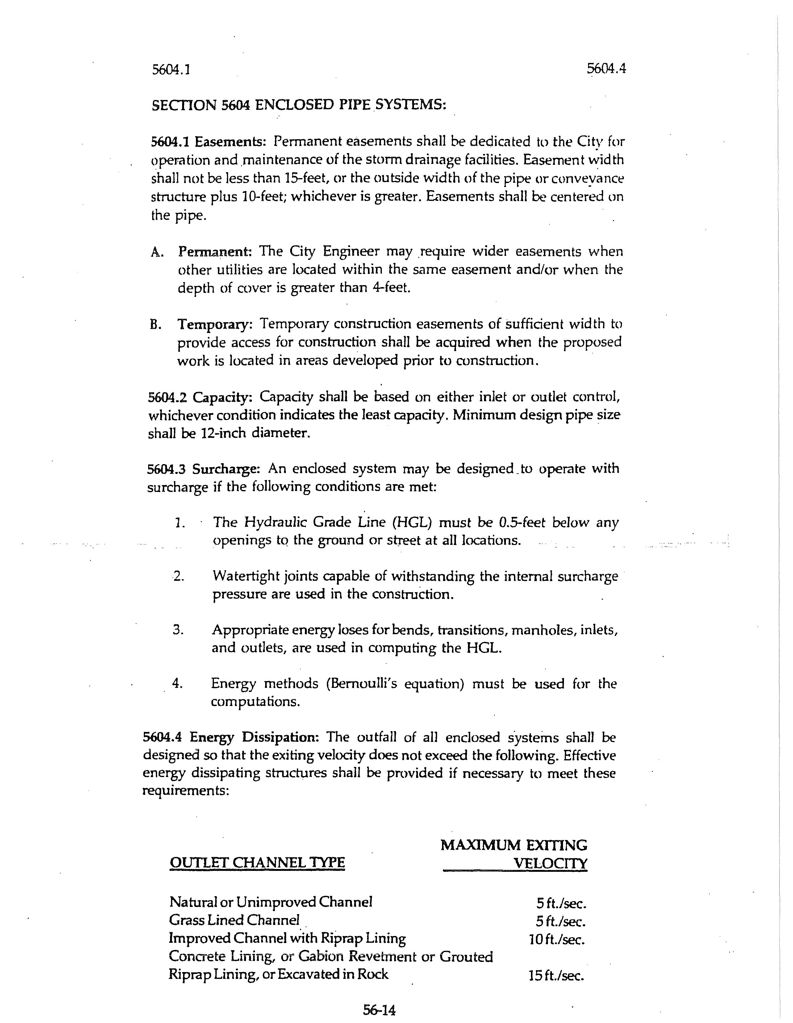
5604.4 Energy Dissipation: The outfall of all endosed systems shall be designed so that the exiting velocity does not exceed the following. Effective energy dissipating structures shall be provided if necessary to meet these requirements:
5604.5 V e locity Within th e S ystem: The velocity within the system shall bt.i between 3 and 20-feet per second. ·
5604.6 Loa ding:
A. Cover: Minimum depth of mver shall be 18-inches.
B. Mi nimum Loa di n g Cond iti ons :
1. Live load: H-20
2. Unit Weigh t of so il cov er: 120 pcf.
3. Rigid pipes shall be bedded and backfilled to provide a minimum factor of safety of 1.5 at the 0.01 - inch crack loading conditilm.
5605.1 Easements: Permanent easements shall be dedicated to the City for operation and maintenance of open channels.
A. Improved Open Chann~s: Easements shall be as wide as the top of bank width; plus JO-feet on each side. Easements shall be continuous between street right-:0f-ways. When an improved channel begins or ends at a point other than the -right~f-way of a dedicated street, a JS.foot or wider easement graded so as to permit access by truck shall be dedicated from the end of the cha·nnel to a street right-of- way.
B. Natural Channels: Natural open channel easements shall be the area between · the lines of intersection of the natural ground with a plane 12-inches above the design water surface, plus 10-feet measured horizontally on each side thereof; however the width of the easement shall not be less than 30-feet and the width shall be increased if J1ecessary to permit access by truck along the entire length of the channel.
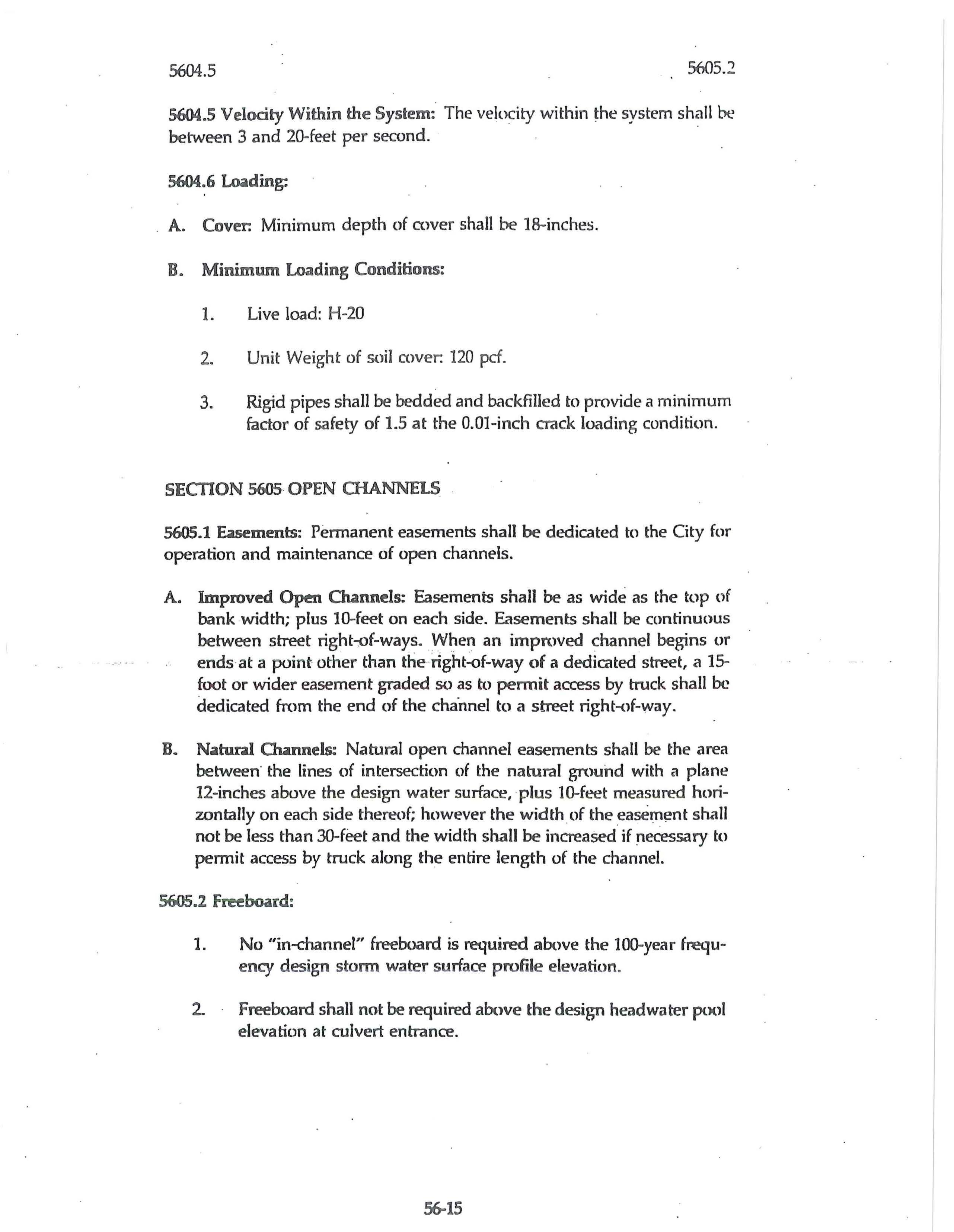
5605.2 Freeboard:
1. No "in-channel" freeboard is required above the 100-year freque ncy d es ign s to rm w a ter su rface p rofile e le va tion
2 Freeboard shall not be required above the design headwater pc.xll elevation at culvert entrance.
5605.3 Channel Linings:
1. All improved channels shall be lined to the minimum of the 10year frequency design storm water profile elevation plus 0.5--foot freeboard minimum.
2. All channel linings, except twf, shall contain provision for relieving back pressures and water entrapment at regular intervals.
3. Lining height on the concave side of curves shall be increased by:
y = Dwhere: 4
y = Increased vertical height of lining in feet.
D = Depth of design flow in feet.
Increased lining height shall be transitioned from y to zero feet over a minimum of:
a. 30(y) feet downstream from the point of tangency (P.T.).
b. lO(y) feet upstream from the point of rurvature (P.C.)
5605.4 Lining Material: The following types of lining material and minimum thicknesses shall be used to control damage and erosion. All riprap, grouted riprap, and gabion linings shall be designed with a filter fabric in conformance with Section 2605.2.C.2 ·
A. Improved Open ~els: Below the 10-year hydraulic grade line +6 inch Freeboard elevation~
DESIGN FLOW VELOOTY - FPS
0 to 10
0 to 15
Over 15
Riprap - 15-inches minimum thickness
Grouted riprap, gabion revetment or paved concrete
Paved concrete or sound in situ bedrock
B. Overflow Open Clunnels: Above the elevation of the 10-year hydraulic grade line + 6-inch Freeboard:
Less than 3 0 to 5 0 to 7 0 to 10 -0 to 15
Over 15
Seeded. Sod, staked
Erosion control blanket as approved by the Oty Engineer
Riprap - 15-inches minimum thickness
Grouted riprap, gabion revetment or paved concrete
Paved concrete or sound in situ bedrock
C Other Lining Materi.tls: Other types of lining materials not specifica11y listed above may be used when.approved by the City Engineer.
5605.S Side Slopes: Side slopes shall not be steeper than:
1. 3 horizontal to 1 vertical for turf lining.
2. 2 horizontal to 1 vertical for all other lining materials.
3. Flatter if necessary for stability of slopes.
5605.6 Alignment Changes: Alignment changes shall be achieved by curves having a minimum radius of:
R = VW where: 8D.
R = Minimum radius on centerline in feet
V = Design velocity of flow in feet per second
W = Width of channel at water surface in feet
D = Depth of flow in feet
5605. 7 Special Improved Channeis: Improved open channels having a design cross sectional flow area of greater than 100-square feet at peak disc. charge from a 10-year storm may be designed to reduce the height of concrete/rock lining to that required to convey a 2-year storm; subject to the following special requirements:
1. Sod or natural vegetation above the structural lining shall be provided:
2. The elevation of the structural lining material shall be a minimum of 18-inches above the adjacent channel flow line. 56-17
5605.B Vertical Wal1 Channels: Vertical walls may be used for structural lining of improved channels; subject to the following special requirements:
1. Walls shall be designed and constructed to act as retaining walls.
2. Adequate provisions shall be made for pedestrian entry/exit from the channel.
5606.1 Scope: This section governs the requirements and design of stormwater detention and retention facilities.
5606.2 Easements: Easements shall be dedicated to the city to provide adequate access for inspection, construction, and maintenance of all public detention faciii°ty components. The owner shall dedicate the detention· facility and ·easements upon a1mpletion of construction and approval by the City Engineer. This shall be land occupied by the facility, plus a 20-foot wide strip around the perimeter of the highest elevation attained by the design storage volume, plus an access easement 20-feet in width between the facility and a public street, except:
J. Private detention facilities as described in Section 5601.2.
2. When multi-purpose wet facilities are planned or are suitable for use as private aquatic recreation or for aesthetic enhancement of the owner's property. · ·
3. When multi-purpose dry facilities incorporate surface recreational improvements. · ·
4. Other special cases.
5606.3 Maintenance and Continued Performance: Maintenance of priv_ate detention facilities shall be the responsibility of the property owner and shall include:
1. Debris removal ~nd deaning
2. Cutting of vegetation
3. Repair of erosion
4. Removal of silt
5. Maintenance of structural facilities, including outlet works, not located in a public drainage easement
6. Annual or more frequent inspections to assure that the detention basin has full storage capacity and all inlet and outlet structures are fully functional. ,
A. General Provisions: The criteria set forth herein are applicable to detention facilities:
1. Having I ,(XX} acres or less area tributary to the facility.
2. Impoundments formed by dams which ·are greater than 10-feet in height. Dams which are greater than 10-feet in height but do not fall into state or federal requirement categories shall be designed in accordance with SCS Technical Release No. 60, "Earth Dams and Reservoirs", August 1981, as Class "C" structures.
3. Other agencies have criteria and regulations pertaining to drain.,. age systems which may complement this criteria. State and federal laws and regulations pertaining to dams shall take precedence over this criteria to the extent that detention facilities may be classified as "dams" thereunder.
a. Federal Insurance Agency - Aoodplain Regulations and Im• plementing Ordinances Adopted by Municipalities: Drainage systems designed_ within the limits of the designated 100-year floodplain on the principal stream shall be designed to convey the fl(xxf as defined by applicable published floodpl~in information studies. For areas located in FIA Zone "A" outside the detailed study area, the Developer shall prepare studies and calculations establishing the floodplain, elevation and width. These calculations shaU be submitted to the reviewing agency for approval.
·b. Missouri Department of Natural Resources: Rules and regulations of the Dam and Reservoir Safety Council shall apply to those Missouri structures classified as dams thereunder.
c. Kansas State Board of Agriculture: Regulations of the Water Resources Division shall apply.
B. Release Rate: The maximum release rate from any development for the 100-year and more frequent storms shall not exceed 1.8 c.f.s. per tnbutary acre. When areas outside the development are also tributary, their inflow hydrograph(s) may be added to the above maximum release rate to determine the total maximum release rate. ff the downstream conditions dictate a lower release rate, then the above release rates do not govern.
C Detention Basin Size: For purposes of evaluation, projects will be classified in two categories according to the acreage of tributaiy area.
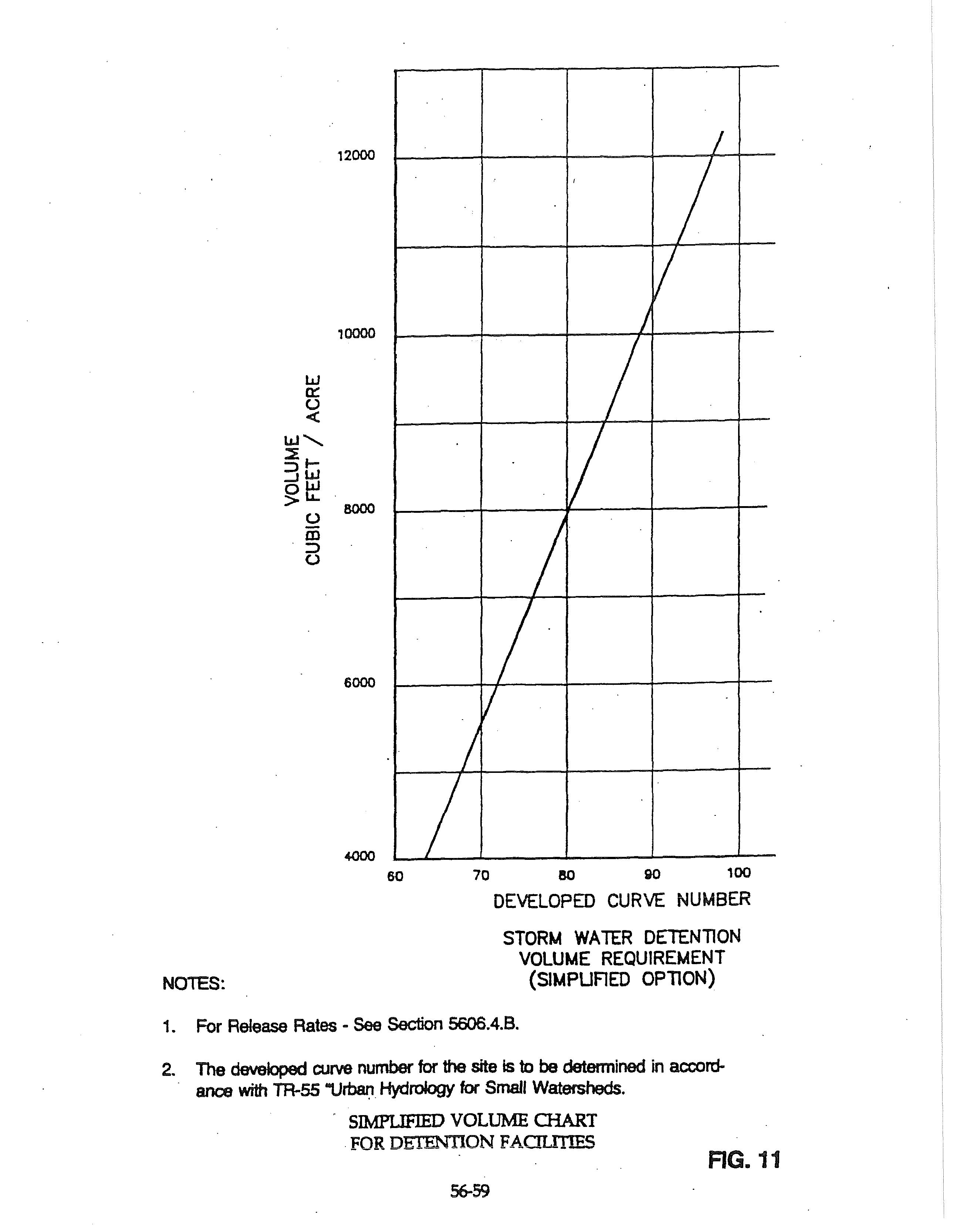
1. Less than 10 acres: Volume of detention for projects having 10 acres or less tributary to the detention facility may be evaluated using either the "Simplified Volume" Figure 11 or by the more precise methods set forth in Section 5606.4.C2.
2. Over 10 acres: For projects of more than 10 acres tributary area the owners/engineers may utilize methodology outlined in Technical Release No. 55 "Urban Hydrology for Small Watersheds," June, 1986. A Type 2 rairifall distribution shall be the required storm hydrograph. Hydrologic simulation models shall be based on not less than Antecedent Moisture Condition Il. Detention storage shall be based upon the allowable release rate during the 100-year storm with the development in place.
D. Principal Spillways: The principal spillway shall be designed to meet the following requirements:
1. The principal spillway shall be designed to function without requiring attendance or operation of any kind or requiring use of equipment or tools, or any mechanical devices.
2 All discharge from the detention .facility when in.flow is equal to or less than the 100-year inflow shall be via the principal spillway(s).
3. The design shall allow for discharge of at least 80 percent of the detention storage volume within 24 hours after the peak or center of mass of the inflow has entered the detention basin.
4. The design discharge rate via the principal spillway shall continuously increase with increasing head and shall have hydraulic characteristics similar to weirs, orifices or pipes. 56-20
E. Emergency Spillways: The emergency spillway may either be a,mbined with the principal spillway or· be a separate structurl' or channel. Emergency spillways shall be designed so that their crest elevation is 0.5-foot or more al>ove the maximum water surface elevation in the detention facility attained by the 100-year storm.
F. Outlet Works: Outlet works amsisting of valves, gntes, pipes, and other devices as necessary to completely drain the.facility in 72 hours or less when required for maintenance or inspection shall be provided.
G. Erosion Control: Principal spil1ways and outlet works, as well as conveyance system entrances to detention basins, shall be equipped with energy dissipating devices as necessary to limit the peak discharge velocity. See Section 5604 for velocity criteria.
5606.5 Detention Methods: In addition to the foregoing ciiteria, the following shall be applicable, depending on the detention altemative{s) selected:
A. Wet Bottom Basins/Retion Facility: For basins designed with permanent pools:
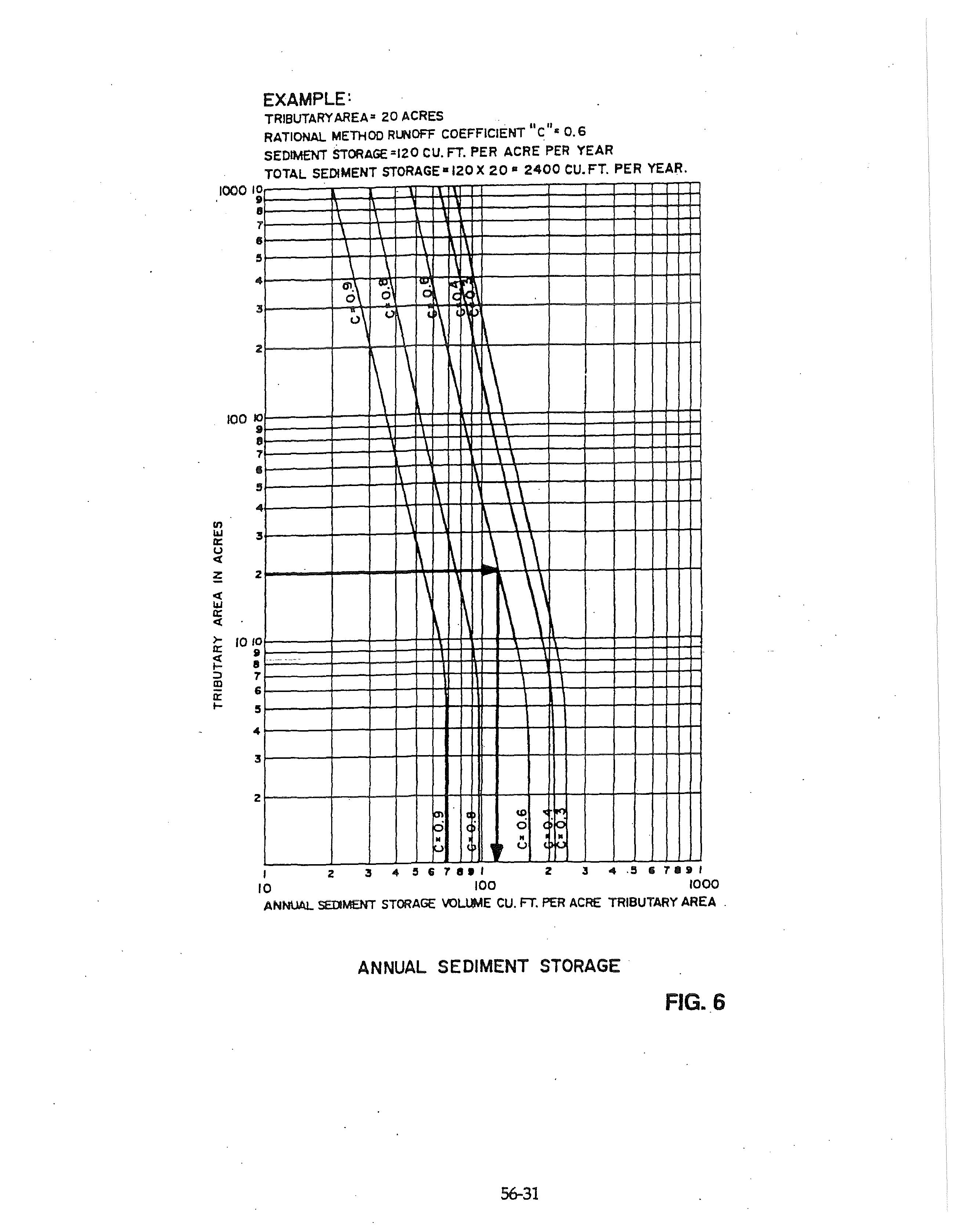
1. Minimum Depths: The minimum normal depth of water before the introduction of excess stormwater shall be four feet plus a sedimentation allowance of not less than 5 years accumulation determined in accordance with Figure 6. The side slopes of dry and wet basins shall conform as dosely as possible to regraded or natural land contours, and should not exceed three horizontal to one vertical. Slo~s exceeding this limit sha11 require erosion control and safety measures.
2. Depth for Fish: If the pond is to a>ntain ·fish, at least <.m~uarter · of the area of the permanent pool.must have a minimum depth of ten-feet plus sedimentation allowance.
B. Dry Bottom Basins/Detention Facility: For basins ·designed to be normally dry:
1. Interior Drainage: Provisions must be incorporated to facilitate interior drainage to outlet structures. Grades for drainage facilities shall not be less than two percent on turf. Concrete swales, with a minimum gradient of 1.0 percent, may be used as. needed to conduct storm water from turfed bottom areas to the outlet structure.
2. Earth Bottoms: Earth bottoms shall be seeded or sodded.
3. Multipurpose feature: These shall be designed to serve seamdary purposes for n.'Cfeation, open space, or other types of use which will not be adversely affected by occasional or intermittent flooding, if possible.
C. Anti-Clogging Protection: Trash racks or other approved devices shall be installed where required to insure that the principal spillway(s) will remain functional.
D Rooftop Storage: Detention storage may be met in total or in part by detention on roofs. Details of such designs shall include the depth and volume of storage, details of outlet devices and downdrains, elevations and details of overflow scuppers, and emergency overflow provisions. Connections of roof drains to sanitary sewers are prohibited. Design oadings and special building and structural details shall be subject to approval by the City Engineer.
E. Parking Lot Storage: Paved parking lots may be designed to provide temporary detention storage of stormwater on a portion of their surfaces. Generally, such detention a_reas shall be in the more remote portions of such parking lots. Depths of storage shall be limited to a maximum depth of seven inches, and such areas shall be located so that access to and from parking areas is not impaired. ·
F. Other Storage: All or a portion of the detention storage may also be provided in underground or surface detention areas, including, but not limited to, oversized storm sewers, vaults, tanks, swales, etc.
5606.6
A. Time of Concentration and Travel Time: Use methods as outlined in Technical Release No. 55, "Urban Hydrology for Small Watersheds," Chapter 3.
B. Temporary Storage Volume: A preliminary value of the storage requirement may be obtained through methods outlined in Technical Release No. 55, Chapter 6 or other acceptable methods. The storage shall be checked during routing of design hydrographs through the basin and adjusted appropriately. ·
C. Hydrograph Routing: The storage indication method (Modified Puls) of routing a hydrograph through a detention basin may be utilized. Reference: "Introduction to Hydrology," by Warren Viessman, Jr., John W. Knapp, Gary Lewis, Second Edition, Section 7-2.
5606. 7 Required Submittals The Owner shall submit the following information and data to the Gty Engineer.
1. Elevation-area-volume curves for the storage facility including notation of the storage volumes allocated to runoff, sediment, and permaneni risidual water storage for other uses (wet basins only). -
2. Inflow hydrographs for the 10-year and 100-year recurrence interval design storms. 56-22.
3. 4.
Stage-discharge rating curves for each spillwny and for combined spillway discharges. ·
Routing curves for the 10-year nnd 100-year recurrence interval design storms with time plotted as the abscissa and the following plotted as ordinates:
a. Cumulative inflow volume.
b. Cumulative discharge.
c. Stage elevation.
d. Cumulative storage.
5606.8 Additional Requirements:
A. Access: Provisions shall be made to permit nccess and use of auxiliary equipment to facilitate emptying, _cleaning, maintenance, or for emergency purposes.
B. Underground Storage: Underground detention facilities shall be designed with adequate access for maintenance (cleaning and sediment removal). Such facilities shall be provided with positive gravity outlets. Venting shall be sufficient to prevent accumulation of toxic or explosive gases.
5607.1 Scope: This section governs the preparation of plans for stormwate~ system projects.
5607.2 General: The plans shall include all information necessary to build and check the design of storm drainage systems. The plans shall be nrr.mgcd as required by the City Engineer. Standard drawings. of the City shall be included by reference only. Plans shall be sealed by a Registered Professional Engineer and shall be submitted to the City Engineer for review and approval.
5607.3 Scale: Plans shall be drawn at the following minimum scales. Larger scales may be needed t~ clearly present the design. Bar scales shall be shown on each sheet for each scale.
Plan: Profile: Vertical: Horizontal:
Cross Sections: Vertical: Horizontal:
Drainage Area Map:
1-inch = SO-feet
1-inch = 10-feet 1-inch = 50-feet 1-inch = 5-feet 1-inch = 5-feet
On site: 1-inch = 200-feet
Off site: 1-inch = 1,000-feet
¼-inch= 5607.4 Required Information:
Structural Plans: _Graphic Drawings:
1-foot Varies
A. · Drainage Area Map: A drainage map shaJl ·be included and shall contain the following:
1. Ridge line of the area tributary to each principal element of the system.
2. Note the area in acres. 5607.4 5607.4
3. Note the runoff coefficient C for each area.
B. Plan View: All designed stonn drainage systems shall be drawn in plan view and shaU contain the following:
I. North arrow and bar scale.
2. Ties to permanent reference points for each system located outside of the street right-of-way.
3. Identification and location of each pipe, culvert, inlet, structure, and existing utility affecting construction.
4. Right-of-way, property, and easement lines. The 100-year flood plain and setback from the top of bank of an open channel to any building.
5. Existing man-made and natural topographic features, such as buildings, fences, trees, channels, ponds, streams, etc., and all existing and proposed utilities.
6. Location of test borings.
7. Existing and finish grade contours at intervals of 2.0-feet or less in elevation; or equivalent deµii] indicating existing and finish grades and slopes.
8. A uniform set of symbols subject to approval by the Oty Engineer.
9. The centerline of open channels within SO-feet of an enclosed drainage system and showing the direction of flow.
10. The existing and proposed drainage systems 100-feet upstream and 100-feet downstream from the development.
C. Profile View: All designed storm drainage systems shall be drawn in profile view and shall contain the following:
1. Existing and finish surface grade along the center line of pipe (except street centerline may be used whim construction includes street construction).
2. Length, size and slope of each line or channel _segment. Slope shall be expressed in percent.
3. Headwater elevation at the inlet end of each culvert.
4. Aow line (invert elevation in and out at each structure).
5. Each existing utility line crossing the alignment shall be properly . located and identified as to type, size and material.
6. Test borings.
7. All station and invert elevations of manholes, junction boxes, inlets or other structures.
8. The profile shall show existing grade above the centerline as a dashed line, proposed finish grades or established street grades by solid lines; and shall show the flow line of any drainage channel, either improved and unimproved, within SO-feet of either side of the centerline. Each line shall be properly identified. The proposed sewer shall be shown as double solid lines properly showing the top of the pipe.
9. All manholes, inlets or other structures shall be shown and labeled with appropriate "Standard Drawing" designation.
D. Cross Sections: Cross sections shall be drawn for all open channels. Sections shall be at appropriate intervals not greater than SO-feet. Additional sections shall be drawn at aII structures and intersecting drainage systems. The following shall be indicated on each section:
1. Ties from centerline to baseline.
2. Existing and proposed grade line.
3. Elevation of the proposed flow line.
4. Cut and fill end areas if required for bid quantities~
_ E. _Design. Information for Each Part of the ·System: The- plans shaU present design information for each culvert, structure, facility, pipe and channel segment and shall contain the following:
1. Tributary area in acres.
2. Design discharge and capacity in cubic feet per second.
3. Runoff coefficient C, design storm return frequency rainfall intensity and Manning's "n".
4. Discharge velocity at design flow.
5. Hydraulic grade line.
6. Type and grade of material (gage, class etc.).
Schedules which indicate an variable dimensions and elevations covered by standards or "typical" drawings shall be shown on the plans. All design details for nonstandard structures sha1J be indicated on the plans. A minimum of one plan view and one sectional view shall be shown on the plans for each structure. Additional views may be required if necessary to clearly define the design. A reinforcing bar list is not required. However, the grade, type, size and location of the bars shall be clearly indicated on the plans.
I. · NOAA Technical Memorandum NWS HYDR0-35 National Oceanic and Atmospheric Administration Of The Notional Weather Service, Departnwnt Of Commerce Sliver Spring, Md.,June 1977.
2. Technical Paper No. 40, Rainfall Frequency Atlo1 For Durations From 30 Mlnuh$ To 24 Hours And Return Periods From lyr To 100 Yr1. U.S. Weather Bureau, Deportmeni Of Commerce, Woshlnqton,D.C., 1963. ·
3. Design Of Urban Hlohway 0ralnol;Je-stote Of The Art FHWA- rs-79-225 us. Dapcrtment Of Tranaportatkwt Ftdenil Highway Adm!n11tratkwt 1 WoahlnQton, D.C., August 1979.
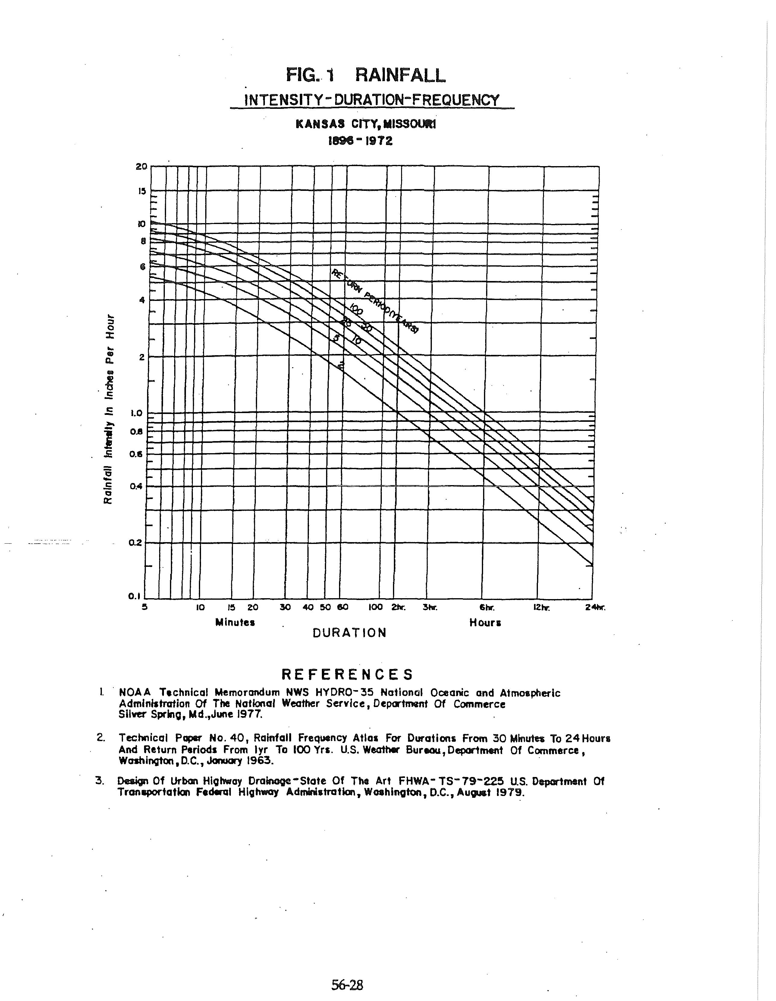
FROM FIGe -1, TI 8 Minutes
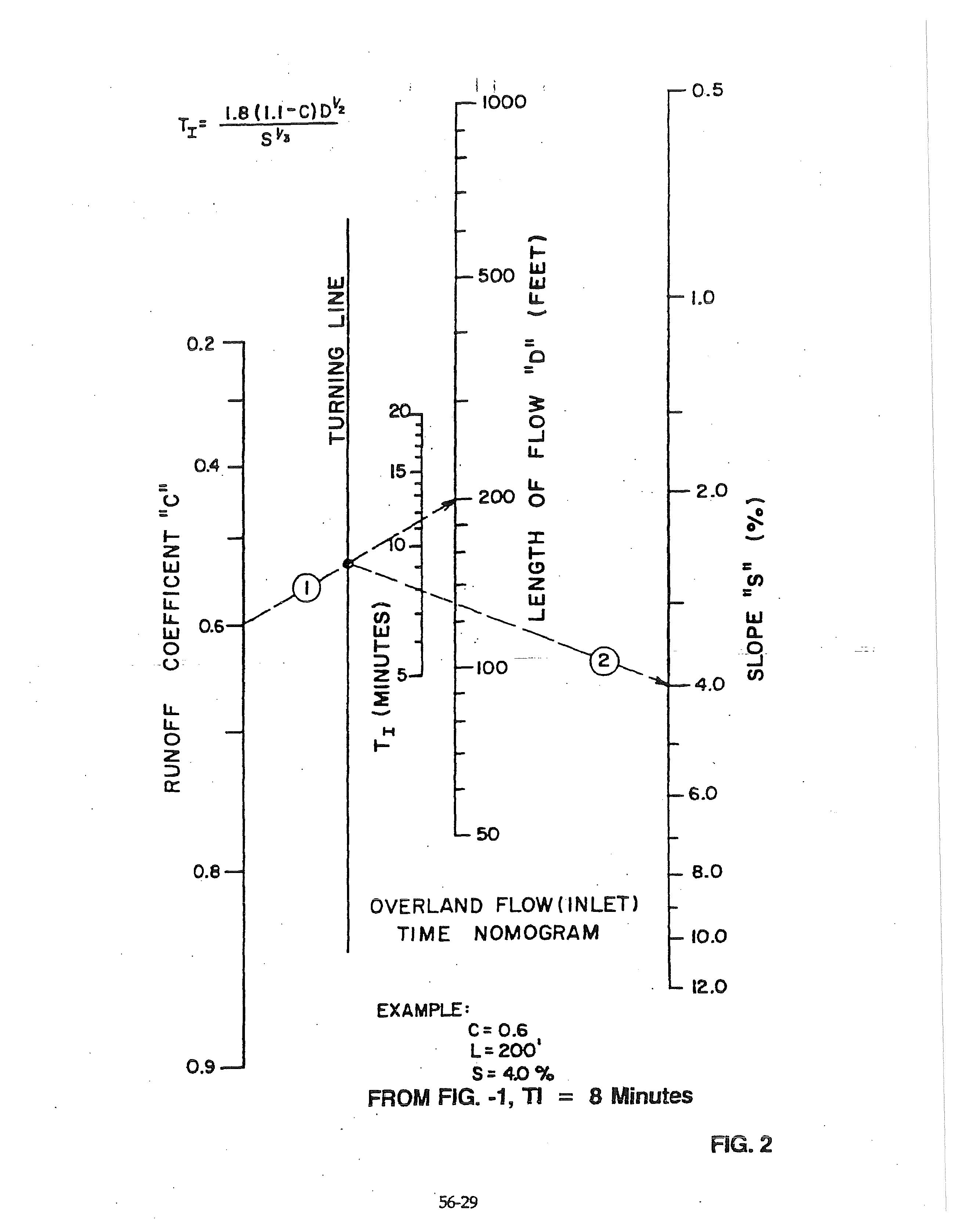
Figure 3 developed by modeling flow in typical representative hydraulic sections using Manning's Equation.
Connect Slope Si Channel Condition to Iocate point on Turnjno Lin•
Extend line from Turning Une throuQh Chonne I Langt~, Read TT
EXAMPLE: TRIBUTARYAREA=
Note: When 50 percent or more of the discharge enters the structure from the surface "k" shall be 1.0. See 5603.2.3.
Wingwall at. 10 ° to 25 ° to barrel
Square edged at crown
Wingwalls parallel (extension of sides)
Square edged at crown
Side-or-slope-tapered inlet
DESIGN AIDE FOR CALCULATING RAINFALL INTENSITY
i = RainfaII intensity in inches per hour.
Tc = Time of concentration in minutes.
Note: Table C is a design aide for use with computers to calculate rainfall intensity in the Kansas City Metropolitan Area using the Steel Formula.
LONG AXIS HORIZONTAL WITH INLET CONTROL
HEADWATER
* AOOIT IONAL SIZES NOT DIMO.S iONED ARE LISTED IN l'ASRICATOR'S CATALOG
HEADWATER DEPTH FOR C. M. PIPE - ARCH CULVERTS
FLOWING FULL n = 0.012 FIG
HEAD FOR OVAL CONCRETE PIPE CULVERTS LONG AXIS HORIZONTAL OR VERTICAL FLOWING FULL na0.012
RG. 7-10
FLOWING
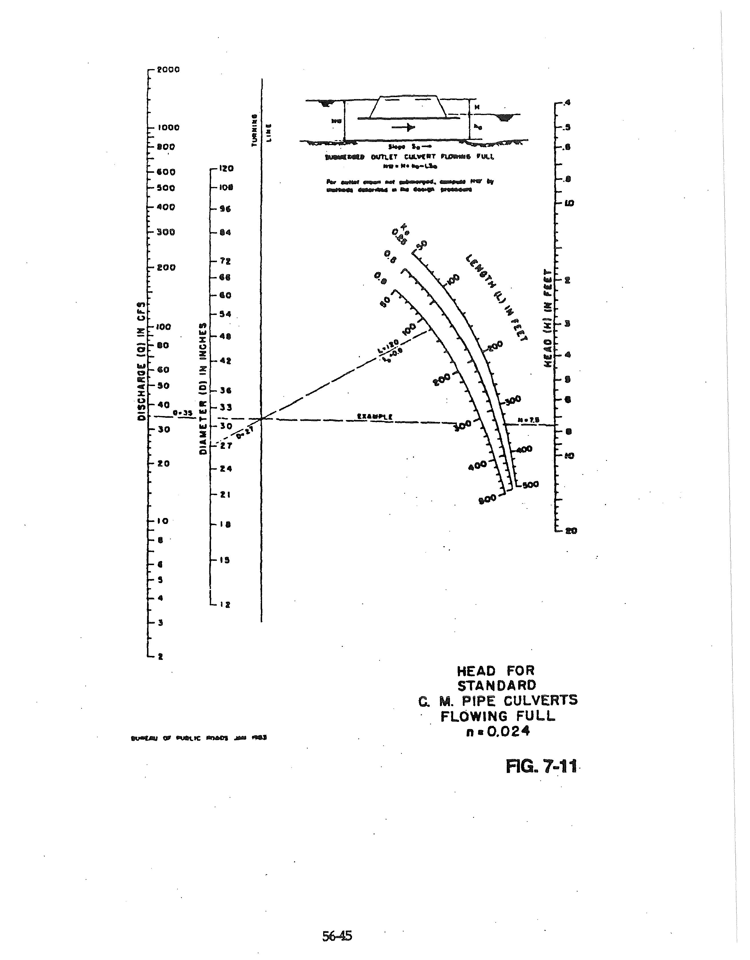
STANDARD C. M. PIPE-ARCH CULVERTS
FLOWING FULL n•0.024
SECTION NO SCALE
FIGURE - 8-0
MINIMUM HYDRAULIC DIMENSIONS
1. Inlet capacities derived from ''The Design of Stormwater Inlets" Johns Hopkins University, 1956
2 Gutter capacity calculated by Izzard's Equation
3. Inlefcapacity is for 1/.t per foot street .crown and inlet throat and transition geometry per Figure 8-0
4. Gutter deflectors are required for inlets on slopes of 4 percent and steeper
5. Linear interpolation within the range ~fthe table is permitted fo~ slopes . and corresponding capacities not shown.
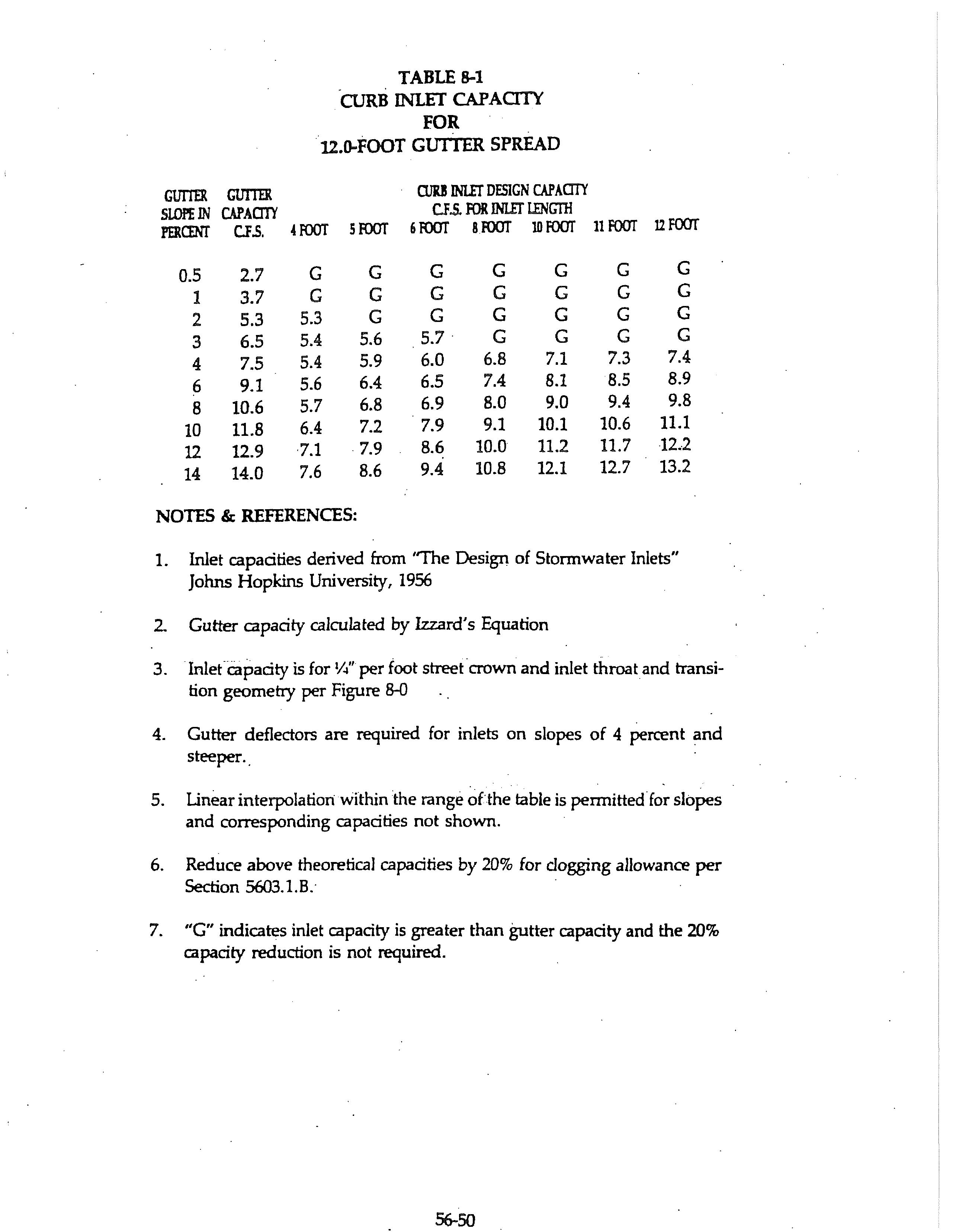
6. Reduce above theoretical capacities by 20% for clogging allowance per Section 5603. 1.B.·
7. "G" indicates inlet capacity is greater than gutter capacity and the 20% capacity reduction is not required.
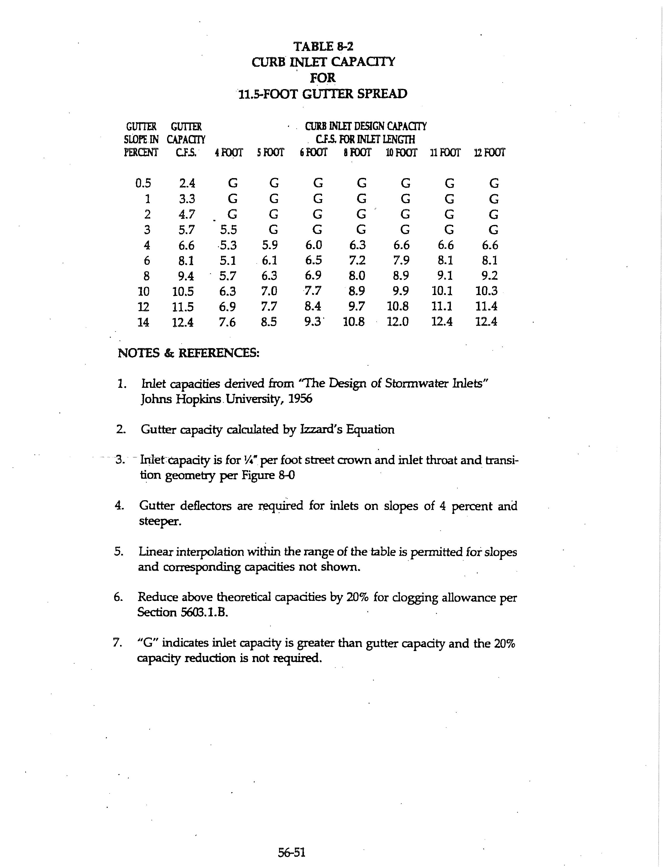
1. Inlet capacities derived from "The Design of Stonnwater Inlets" Johns Hopkins. University, 1956
2. Gutter capacity calculated by Izzard's Equation
3. Inlefcapacity is for¼" per foot street crown and inlet throat and transition geometry per Figure 8-0
4. Gutter deflectors are required for inlets on slopes of 4 percent and steeper.
5. Linear interpolation within the range of the table is pennitted for slopes and corresponding capacities not shown. ·
6. Reduce above theoretical capacities by 20% for clogging allowance per Section 56Cl3. l. B.
7. "G" indicates inlet capacity is greater than gutter capacity and the 20% capacity reduction is not required.
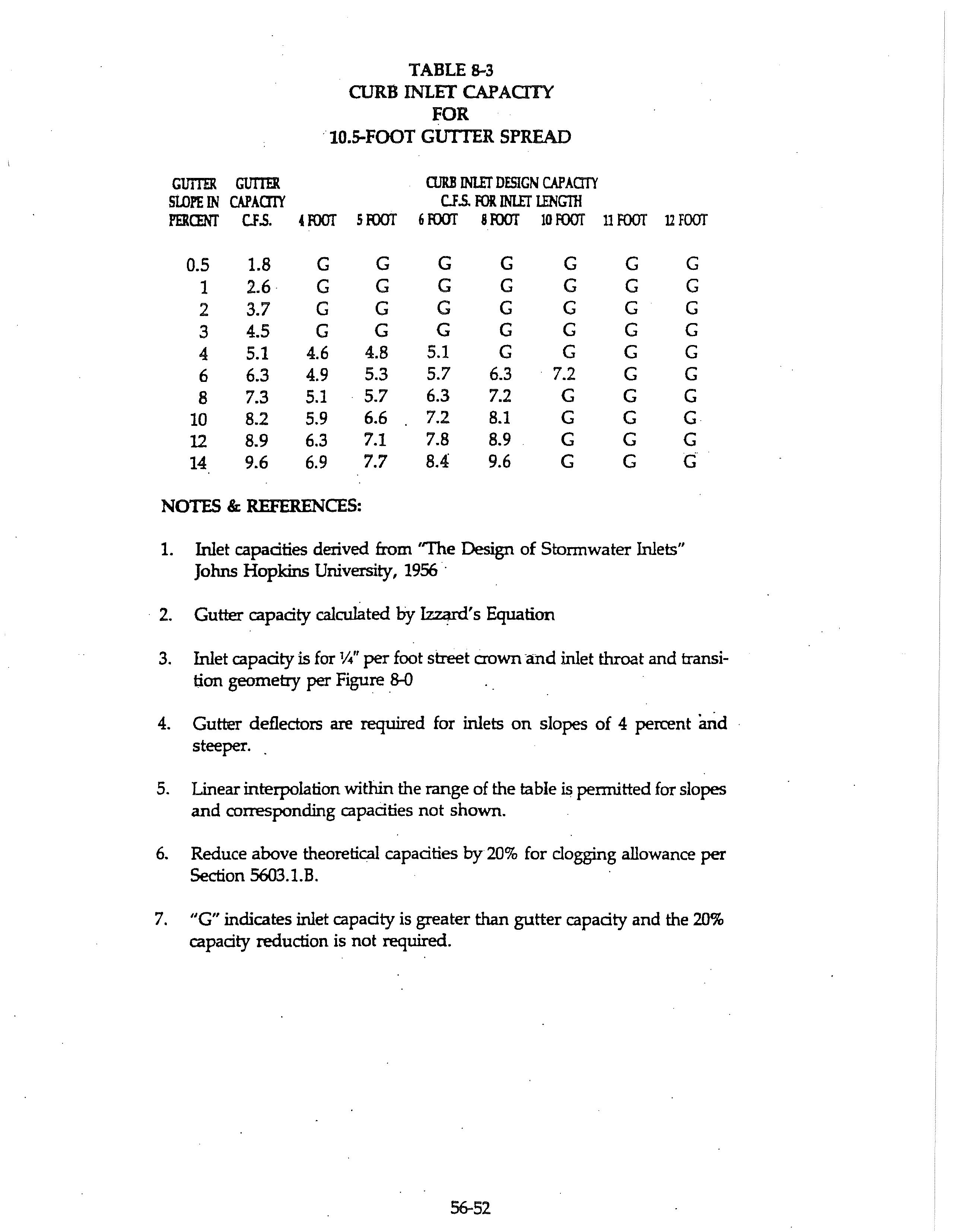
1. Inlet capacities derived from "The Design of Stonnwater Inlets" Johns Hopkins University, 1956 ·
2. Gutter capacity calculated by ~'s Equation
3. Inlet capacity is for ¼" per foot street crown ·and inlet throat and transition geometry per Figure _8-0
4. Gutter deflectors are required for inlets on slopes of 4 percent and · steeper
5. Linear interpolation within the range of the table is pemritted for slopes and corresponding capacities not shown.
6. Reduce above theoretical capacities by 20% for clogging allowance per Section 5603.1.B.
7. "G" indicates inlet capacity is greater than gutter capacity and the 20% capacity reduction is not required.
IIIV!N
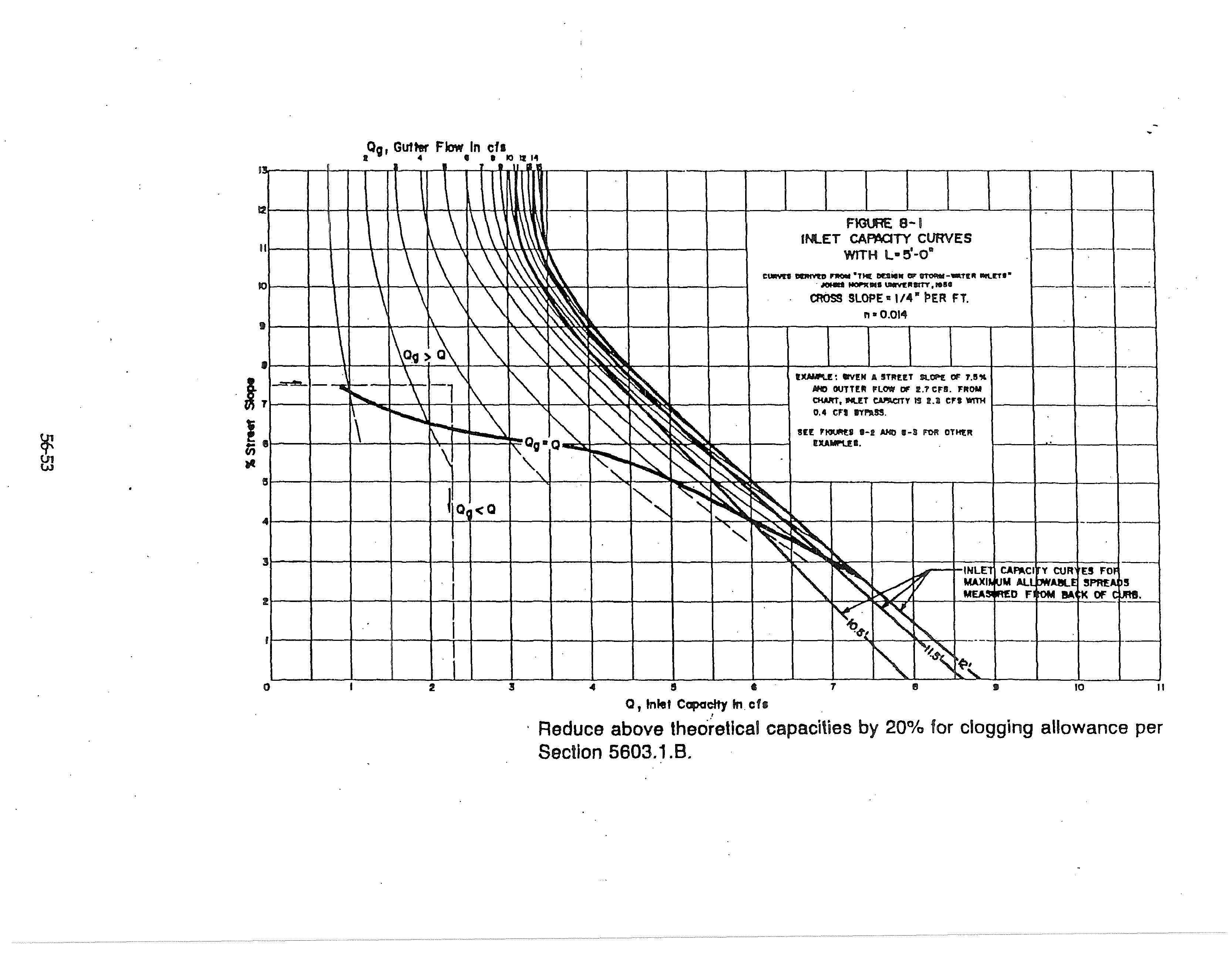
FIGURE 8-2
INLET CA~aTY CURVES WITH L•S'-o•
CIAIYU IM!lllvtll FROM "THE IM!SICK 01' 9TO!IM•·w.tT!II 1Nll!:T9", JOtlMS HOP'II INS lJIIIIVl!'.P!lllTT, ltSI
CROSS SLOPE • I /4" PER FT.
n • 0.014
EXAMP\.E: FmD fll.U CAPAC!T'f IN SUMP 10% !ITREET !ILOPEI FOR A MAXIMUM ALLO'Wt<DLE SPREAO OF 1O.!l'. It.ET
CIJ'N:ITY IS IUI Cf!I.
!IEE FIOURE!I 11 - I AHO 11 • 3 FOR OTHER EXAMPLll!:S.
Reduce above· theoretical capacities by 20% for clogging allowance per Section 5603.1.B~
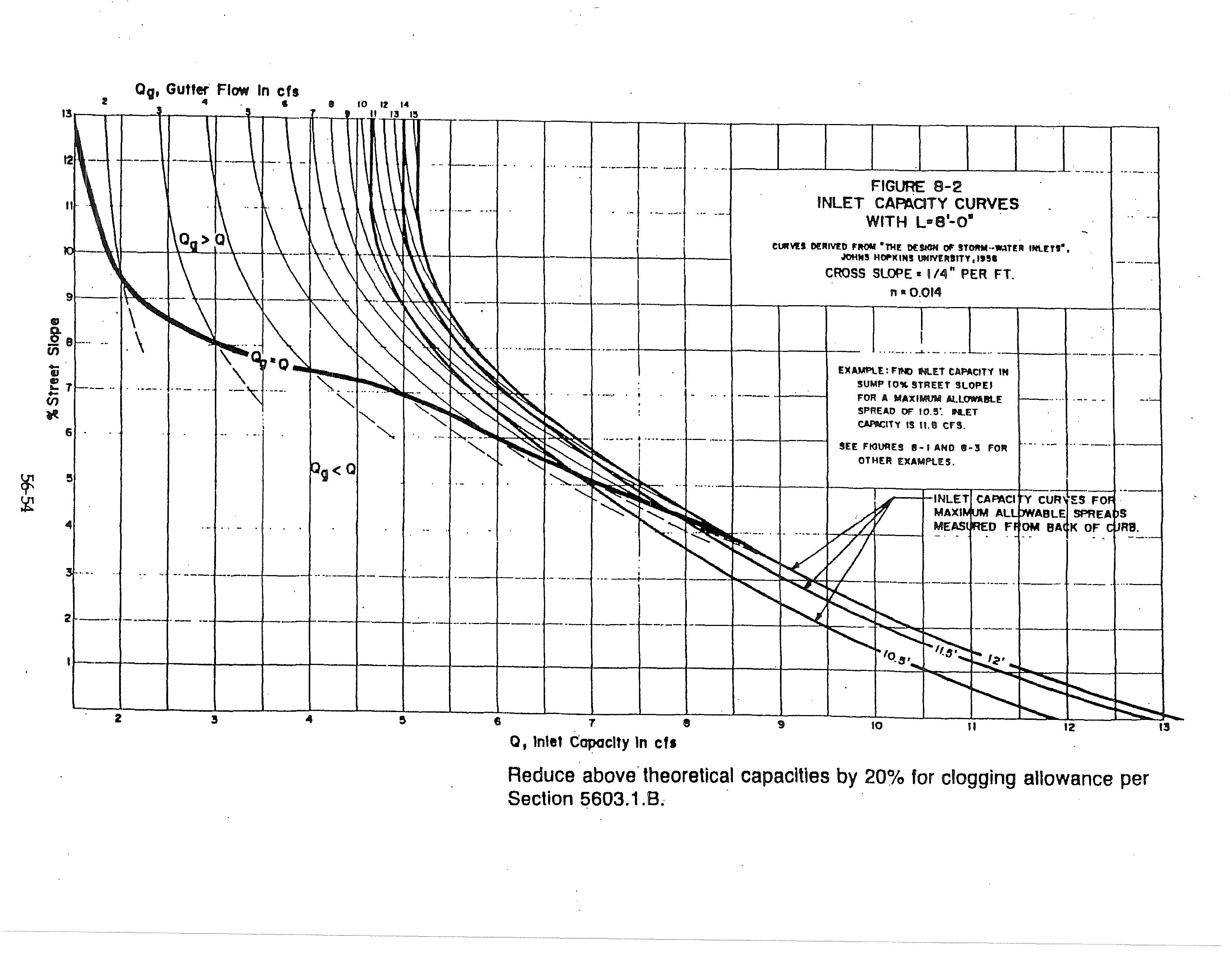
CUIIYU Dl!:AJVf:D P-11101,1 •tHI! Dl!:9- DI' ST"""'--TIIII 1111.tTI", Jffltlll HOl'ICIJIII l.ilY!IIIITY, IHI CROSS SLOPE " 1/4" PER FT.
n• 0.014
DAMl"U: OIYEN A 5Tll££T !lt..<lf•£ OF 8'!1. YIELDS A MAX..._.. ALLOIIIIULE OUTTE.1'! FUlW OF II CFS FOR A 11.5' SPREAD.
ttl': FIGUIII': 1-1 AHO 1-l FOR OTHEII l':XAMPLl!:lll.
Reduce above theoretical capacities by 20% for clogging allowance per Sectior
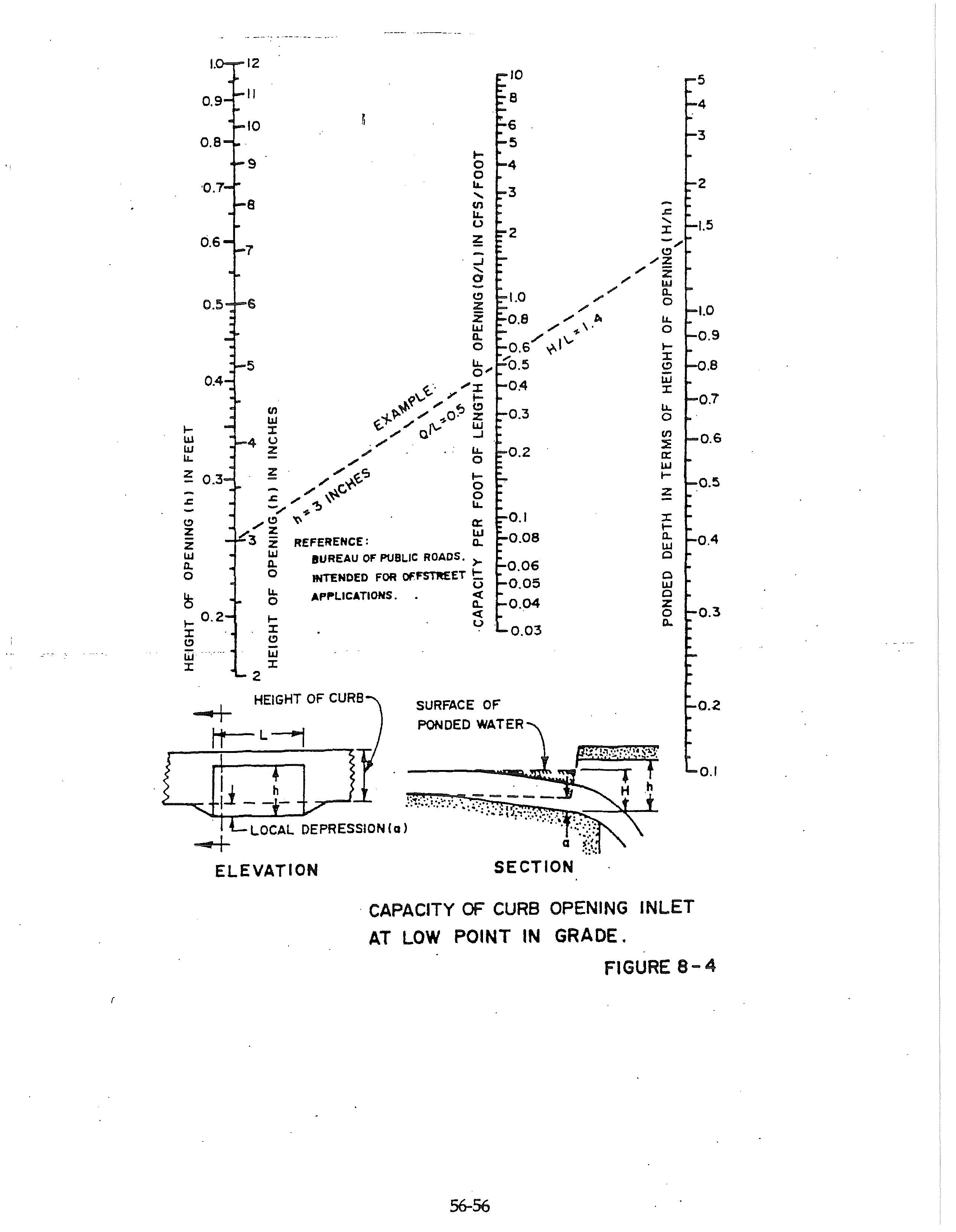
· CAPACITY OF CURB OPENING INLET AT LOW POINT IN GRADE.
NOTES:
1. For Release Rates - See Section 5606.4.B.
2. The developed curve number for the site is to be detennined in accordance with TR-55 "Urbar:, Hydrology for Small Watersheds.
SIMPLIFIED VOLUME CHART FOR DETENTION FACILITIES
