STANDARDS
CITY OF INDEPENDENCE, MISSOURI WATER MAIN INSTALLATION
Last update: April 06, 2021

STANDARDS AND SPECIFACTIONS FOR WATER MAIN EXTENSIONS AND RELOCATIONS Table of Contents EXCAVATION AND TRENCHING Page No. EX-1 Scope 12 FORWARDINSTRUCTIONS TO CONTRACTOR Page No. IC-1 General Statement 1 IC-2 Scope 1 IC-3 Definitions 1 IC-4 Performance and Maintenance Bond 2 IC-5 Insurance 2 IC-6 Licenses, Permits and Certificates 3 IC-7 Pre-Construction Conference 3 IC-8 Construction Notification 4 IC-9 Engineering Plans 4 IC-10 Reference Standards 4 IC-11 Field Changes 4 IC-12 Acceptance of Water Pipe 4 PIPELINE MATERIALS PM-1 General 5 PM-2 Ductile Iron Pipe and Fittings 5 Fitting Metal Thickness 5A PM-3 Polyethylene Encasement 6 PM-4 Valves 6 PM-5 Valve Boxes, Bases, Lids, Covers and Valve Stem Extension 7 PM-6 Fire Hydrant 7 PM-7 Inspection of Materials 9 PM-8 Thrust Restraints 9 EXISTING UTILITIES AND IMPROVEMENTS EU-1 Location of Underground Utilities 10 EU-2 Protection of Property & Existing Improvements 10 EU-3 Removing and Restoring Street Pavement, Driveways, and Other Surfaced Areas 10 EU-4 Maintenance of Traffic 11
Table of Contents (Cont.) EX-2 General 12 EX-3 Blasting 12 EX-4 Unauthorized Excavation 13 EX-5 Removal of Water 13 EX-6 Sheeting and Shoring 13 EX-7 Stabilization 13 EX-8 Trench Excavation 14 EX-9 Highway and Railroad Crossing 16 EX-10 Expedited Crossings 16 EX-11 Barricades and Warning Signs 16 LAYING AND BACKFILL LB-1 Pipe Installation 17 LB-2 Polyethylene Encasement 19 LB-3 Setting Valves and Fittings 20 LB-4 Setting Fire Hydrants 20 LB-5 Blow-off Assemblies 21 LB-6 Air Release Assemblies 21 LB-7 Connections to Existing Mains 21 LB-8 Street Surface Restoration 21 WATER MAINS NEAR SEWERS WMS-1 Horizontal Separation 22 WMS-2 Vertical Separation 22 WMS-3 Unusual Conditions 22 WMS-4 Sewer Manholes 22 WATER MAINS DISINFECTION WD-1 Water Main Disinfection 23 CONCRETE CS-1 Scope 24 CS-2 Concrete 24 CS-3 Mixing 24 CS-4 Forms 24 CS-5 Placing of Concrete 24 CS-6 Curing 25 Drawing CONSTRUCTION DETAILS Drawing No. CD-1 Typical Hydrant Installation: Straight Set 26 CD-2 Typical Hydrant Piping Layout: Straight Set 27 CD-3 Typical Valve and Valve Box Installation – Roadway 28 CD-4 Typical Valve and Valve Box Installation 29 CD-5 Typical Valve Stem Extension 30 CD-6 Typical Thrust Blocking for – Bends 31 CD-7 Typical Thrust Blocking for – Tees 32 CD-7A Typical Thrust Blocking for – Plugs 33
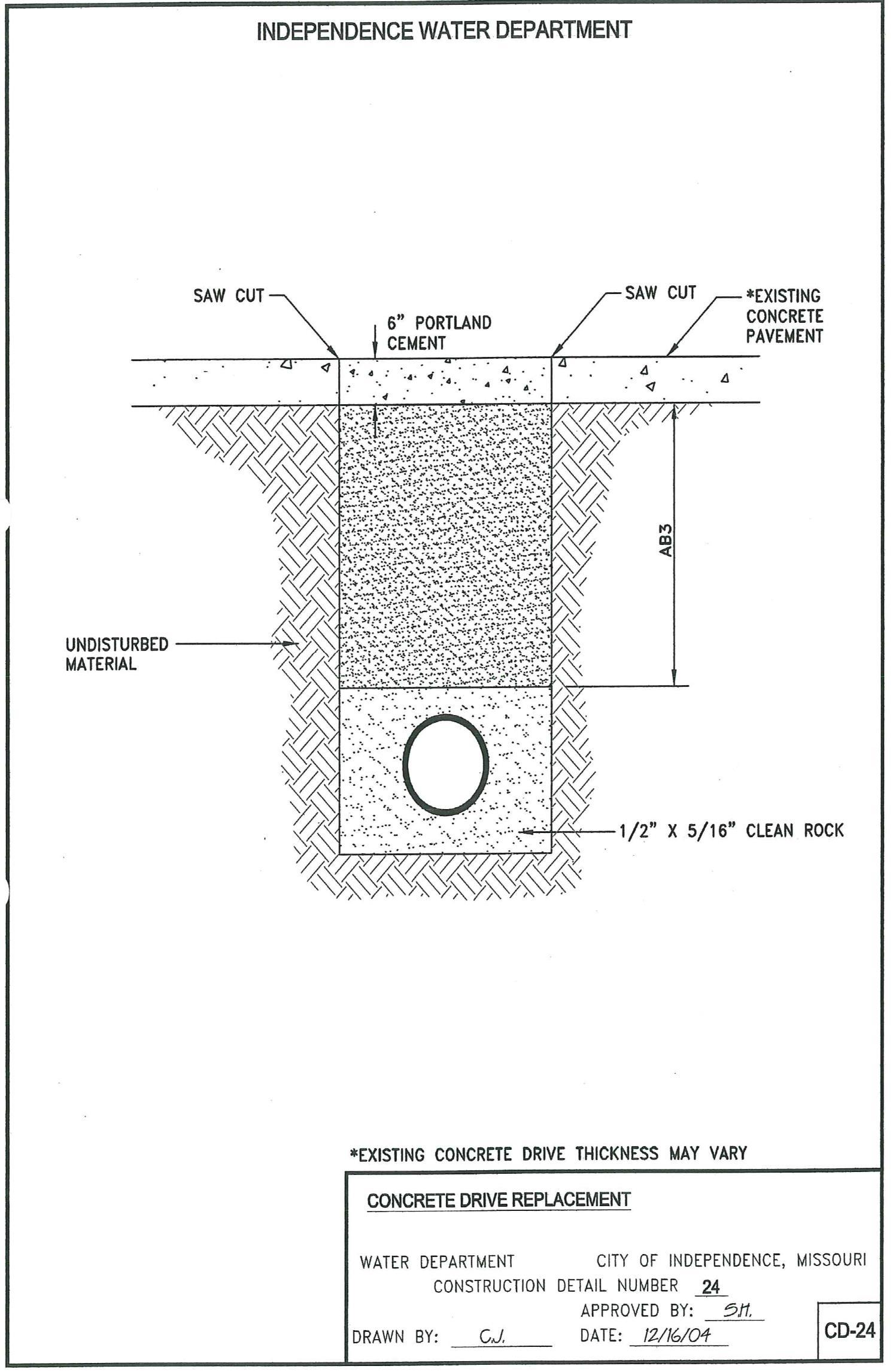
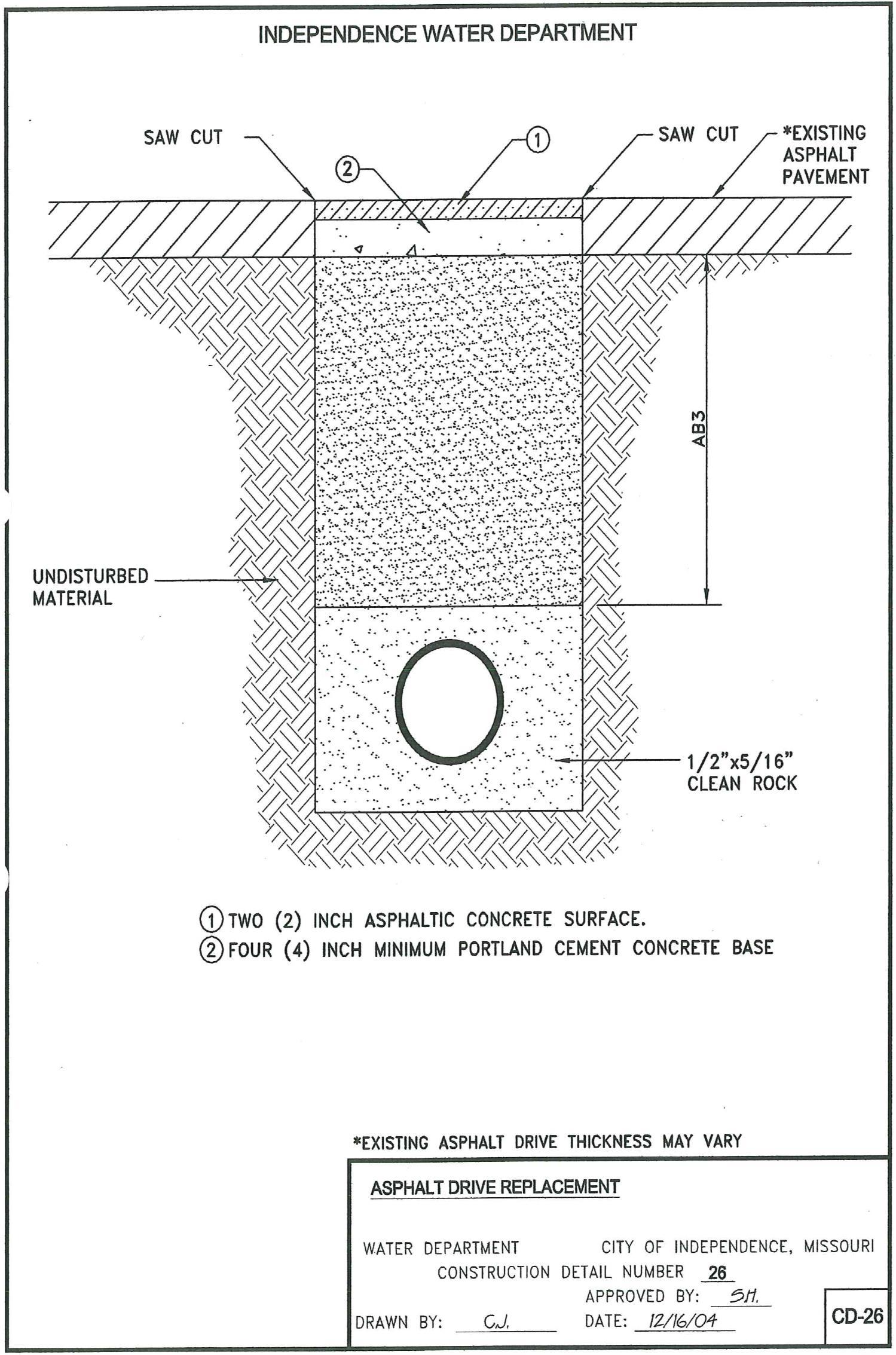
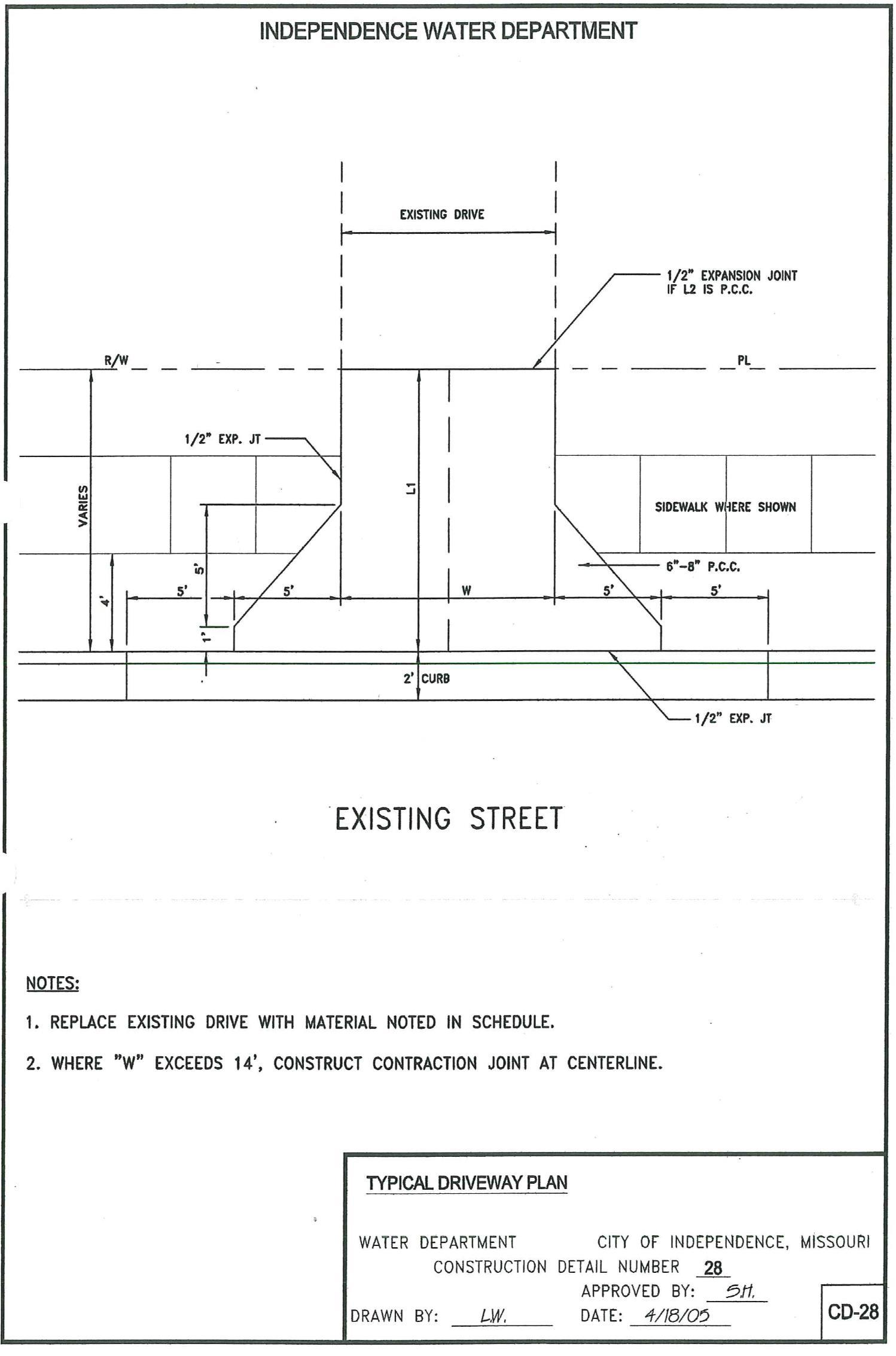
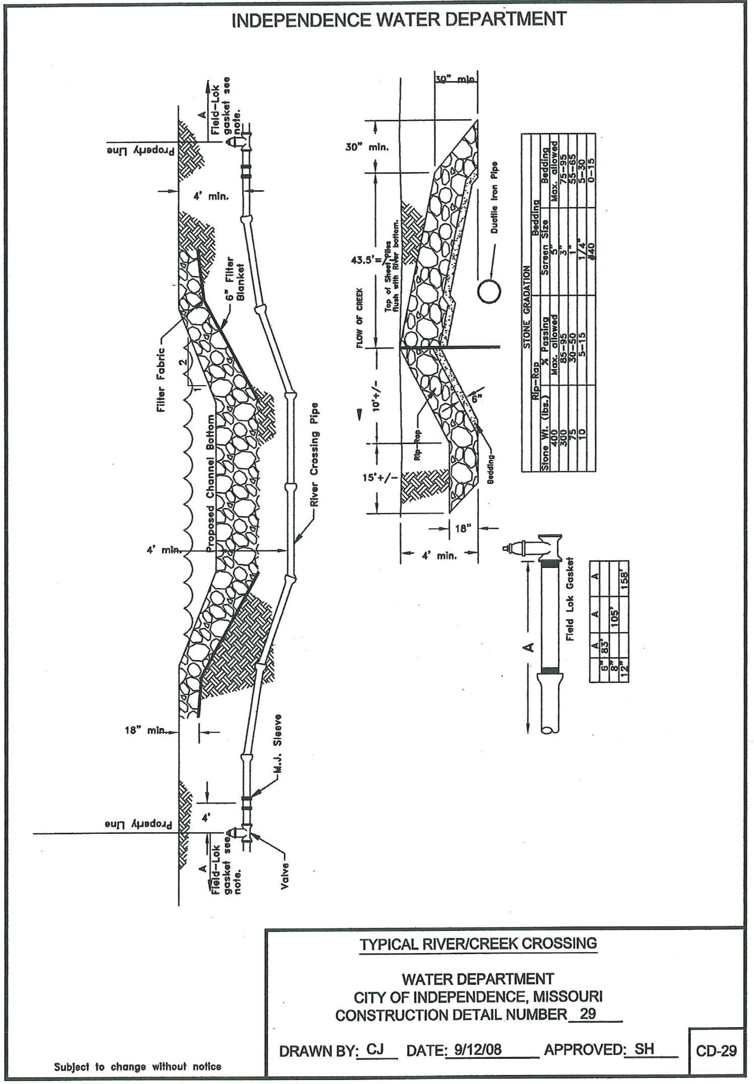
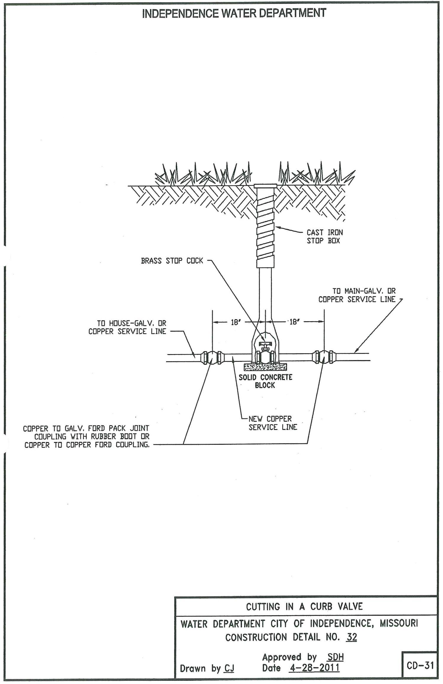
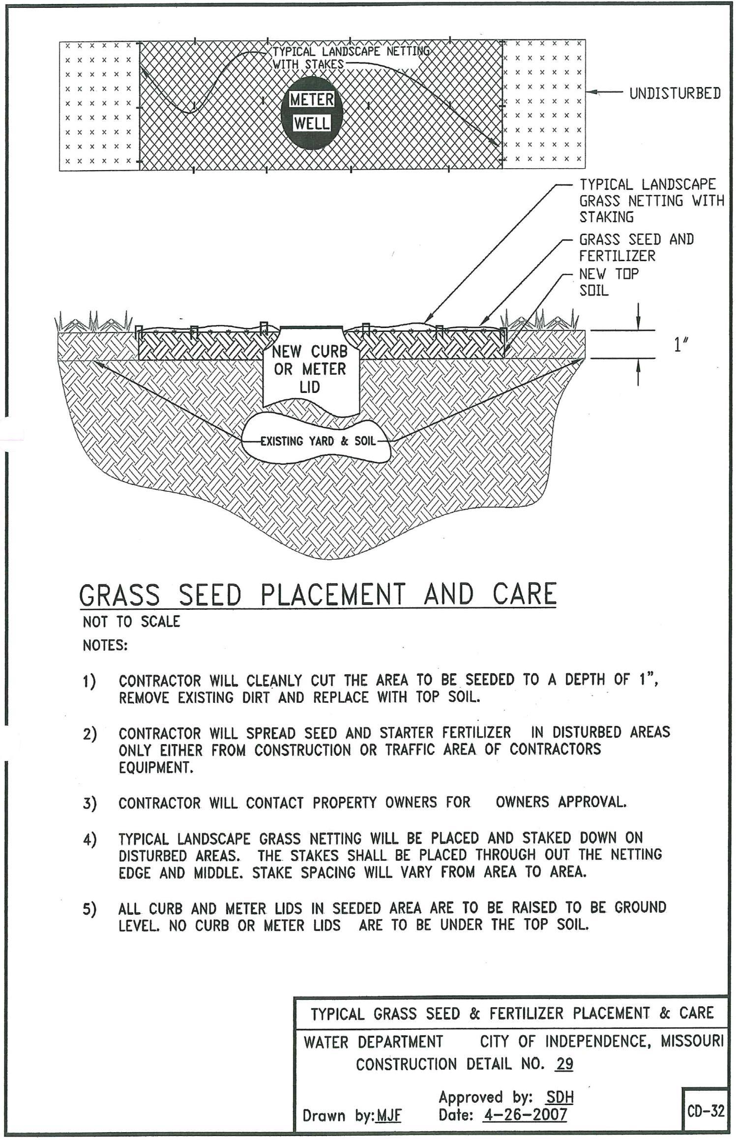
Table of Contents (Cont.) CD-8 TypicalFieldLokGasket InstallationforDuctileIronPipe–11-1/4°,22-1/2°, 45° and 90° (Bends) 34 CD-9 Typical Field Lok Gasket Installation for Ductile Iron Pipe – Tees 35 CD-10 Typical Field Lok Gasket Installation for Ductile Iron Pipe – Dead Ends 36 CD-11 Typical Encasement Under Roadway for Ductile Iron Pipe – 6” thru 36” 37 CD-12 Typical Encasement Under Railroad for Ductile Iron Pipe – 6” thru 36” 38 CD-12A TypicalEncasementUnderRailwayandRoadwayforDuctileIronPipe6”thru 36” 39 CD-13&13A Polyethylene Encasement for Ductile Iron Pipe 40 CD-14 Typical Blow-off Assembly – Dead End 41 CD-15 Typical Blow-off Detail 42 CD-16 Typical Tapping Sleeve Connection 43 CD-17 Typical Blow-off Connection 44 CD-18 Typical Sanitary Sewer Main Crossing Water Main 45 CD-19 Standard Laying Conditions for Ductile Iron Pipe 46 CD-20 Typical Air Release Pit 47 CD-20A Typical 2” Air Release Pit 48 CD-21 Joint Deflection for Ductile Iron Pipe 49 CD-22 Night Plug for Ductile Iron Pipe 50 CD-23 Marker Post Detail 51 CD-24 Concrete Drive Replacement 52 CD-25 Gravel Drive Replacement 53 CD-26 Asphalt Drive Replacement 54 CD-27 City Street Cut Replacement 55 CD-28 Typical Driveway Plan 56 CD-29 Typical River Creek Crossing 57 CD-30 Service Under Storm or Sanitary 58 CD-31& 31A Cutting in a Curb Valve 59 CD-32 Typical Grass Seed & Fertilizer 60
FORWARD
The City of Independence Water Department is dedicated to helping its customers. Experience has shown that a uniform standard for installation for water mains is the best way to accomplish our common goals. These standards are not intended to be restrictive or burdensome, but to assist in expediting water main construction. It is, therefore, required that water main construction comply with these standards.

This booklet is offered to assist architects, engineers, contractors and inspectors in the planning and construction of water mains.
No set of rules or instructions will cover all conditions. The Water Department welcomes and encourages all inquiries concerning unusual or special needs of customers.
The Water Department should be contacted about each project as early as possible to provide time for necessary plan review, job checking, scheduling, and proper coordination.
Due to constant progress in the development of materials and methods, some procedures outlined herein may be modified. Upon request, information will be supplied concerning changes and revisions.
Persons making regular use of this booklet should maintain contact with the Water Department.
City of Independence Water Department
STANDARDS FOR WATER MAIN INSTALLATION INSTRUCTIONS TO CONTRACTOR
IC-1. GENERAL STATEMENT: The purpose of these Standards is to provide for the furnishing of all materials,labor,equipment,tools,superintendence,andotherservicesnecessarytoconstruct,completewith appurtenances, water main extensions as approved by the Water Department.
IC-2. SCOPE: These Standards are general in scope and will refer to conditions which may not be encountered. Any provision of these Standards which pertains to a nonexistent condition and is not applicable to the work to be performed shall have no meaning and shall be disregarded.
IC-3. DEFINITIONS: Any word, phrase, or other expression defined hereunder and used in these Standards shall have the meaning herein given:
DEVELOPER: Anindividual,firm,partnership,jointventure,corporation,companyorassociation who desires a water main extension and who by means of a contract with the City agrees to pay all bills for engineering, labor, and materials used on the design, construction, and installation of said water main extension.
CITY: City of Independence, Missouri.
CONTRACTOR: The individual, firm, partnership, joint venture, corporation, company or associationcontractingwiththedevelopertoperformtheconstructionandinstallationofsaidwater main extension.
DIRECTOR: The Director of the Independence Missouri Water Department or his authorized representative.
DISTRIBUTION MANAGER: The manager of the Transmission and Distribution System of the Independence, Missouri Water Department.
ENGINEER: Unless otherwise specified, the term “Engineer” when used in these Standards and Specifications shall mean the individual, firm, partnership, joint venture, corporation, company or association contracting on behalf of the Applicant to perform the design of said water main extension.
ENGINEERINGSUPERVISOR: TheSupervisoroftheIndependence,MissouriWaterDepartment Engineering Division or his authorized representative. -1-

STANDARDS FOR WATER MAIN INSTALLATION (Cont.)
INSPECTOR: The agent appointed by the Engineering Supervisor to assist in the inspection of all material and labor. The inspector will keep the Engineering Supervisor informed as to progress of the work and the manner in which it is being done. The Inspector has authority to reject defective and improper materials and to suspend any work that is being improperly done, all in accordance with these standards, subject to the final decision of the Engineering Supervisor.
PERMITS,LICENSES,ANDCERTIFICATES: AnofficialdocumentissuedbytheCity,County, Stateorothergoverningbody,authorizingtheconstructionofawatermainextensionorrelocation, or any appurtenance thereto, in an area of their jurisdiction.
PLANS: The official, certified drawings, standard plans, profiles, details, and supplemental drawings or reproductions thereof, furnished by the Engineer which show the location, character, dimensions and details of the work.
SHOP DRAWINGS: All drawings, diagrams, illustrations, brochures, schedules, and other data which are prepared by the Contractor, a sub-contractor, manufacturer, supplier, or distributor and which illustrate the equipment, material, or some portion of the work.
STANDARD: Unlessotherwisespecified,theterm“Standard”referstothemostcurrenteditionof “STANDARDS FOR WATER MAIN INSTALLATION” as distributed by the Independence, Missouri Water Department.
THEWORK: Allworktobedoneandtheequipment,supplies,andmaterialstobefurnishedbythe Contractor on each Water Main Extension.
IC-4. PERFORMANCE AND MAINTENANCE BOND: Before the Water Department will make connection, the Developer or his agent, servant, employee, independent contractor, or such other persons, firm, partnership, corporation, or association by whom such work is to be performed shall file with the Water Department a performance and maintenance bond in an amount equal to the estimated cost of the City’s installation cost conditioned that such work has been done in accordance with the Water Department’s Standardandguaranteeing thework andmaintenanceoftrenches foraperiodofone(1)year from the date of connection.
IC-5. INSURANCE: The Developer or his independent contractor agrees to carry, at his own expense, liability insurancenaming theCity ofIndependence,Missourias beingheld harmless against all claims for damage to property or injury to persons by reason of such construction work.
-2-
STANDARDS FOR WATER MAIN INSTALLATION (Cont.)
The following must be included on Insurance Certificate:
(1) Public Liability Insurance:
(2)
(3) Worker’s Compensation and Employer’s Liability as required by the State of Missouri.
(4) City of Independence must be named as held Harmless.
(5) All certificates of insurance shall state that ten (10) days written notice will be given to the City before the policy is canceled or changed.
AcopyofsaidinsuranceshallbeissuedtotheCityofIndependenceWaterDepartment,Engineering Division,andsaidinsuranceshallremainineffectuntilsaidworkhasbeencompletedandaccepted by the City.
IC-6. LICENSES,PERMITS ANDCERTIFICATES: All licenses, permits,certificates, etc.,requiredfor and in connection with the work to be performed under the provisions of the Water Main Extension AgreementContractshallbesecuredbytheDeveloperorhisContractorentirelyathisownexpensepriorto startinganyconstruction work. Therequirements oftheauthorityorauthoritiesissuingthelicense,permit, or certificate shall be fully complied with, and a copy of said licenses, permits and certificates shall be issued to the City of Independence Water Department, Engineering Division.
IC-7. PRE-CONSTRUCTION CONFERENCE: The Developer or his Contractor will be required to schedulea Pre-Construction Conference with theCityof IndependenceWaterDepartment priorto starting construction of pipeline.
Bodily Injury $300,000.00 Per Person 500,000.00 Per Occurrence Property Damage 500,000.00 Per Occurrence
Auto Liability Bodily Injury $300,000.00 Each Occurrence 300,000.00 Aggregate Property Damage 150,000.00 Each Occurrence 150,000.00 Aggregate or 500,000.00 Combined Single Limit
-3-
STANDARDS FOR WATER MAIN INSTALLATION (Cont.)
IC-8. CONSTRUCTION NOTIFICATION: The Contractor shall give to the Water Department two days notice, in writing, or verbal, of his intent to start to work. The notification must include the following:
(1) Starting Date
(2) Job Number and Location
(3) Foreman’s Name
(4) Contractor’s Phone Number
IC-9. ENGINEERING PLANS: The Developer shall furnish four (4) copies of his engineering plans and specificationsforinstallationofpipingsystemwithnecessaryeasements,pipe,firehydrants,valves,fittings and connections to existing Waster Department mains clearly shown. The plans and specifications will be reviewed by the City of Independence Water Department and one copy will be returned to either the Applicant or his Engineer with either comments to be incorporated into the plans and stamped “RETURNEDFORCORRECTION”orstamped“NOEXCEPTIONSNOTED.” Ifplansandspecifications have comments to be incorporated, or they are disapproved, they must be revised and resubmitted to the Water Department for approval prior to the start of any construction.
IC-10. REFERENCESTANDARDS: Referencetothestandardsofanytechnicalsociety,organization,or association, or to codes of local or state authorities, shall mean the latest standards, code specification, or tentative standard adopted and published at the date of construction, unless specifically stated otherwise.
IC-11. FIELD CHANGES: Any change from the approved plans and specifications shall require prior written approval from the Engineering Supervisor or Inspector.
IC-12. ACCEPTANCEOFWATERPIPE: Whentheworkhasbeencompleted,afinalreviewofthework willbemadebytheEngineeringSupervisorandtheInspectorfordeterminationofacceptancebytheWater Department. Developerwillreceivealetterofacceptancewhenthewatermaininstallationisacceptedinto the distribution system by the Water Department.
-4-
PIPELINE MATERIALS
PM-1. GENERAL: All pipeline materials necessary for the complete installation of the work shall be furnished by the Developer or his Contractor. All materials shall be new and shall comply with the standards that follow unless approval for other is given by the Director.

PM-2. DUCTILE IRON PIPE AND FITTINGS:
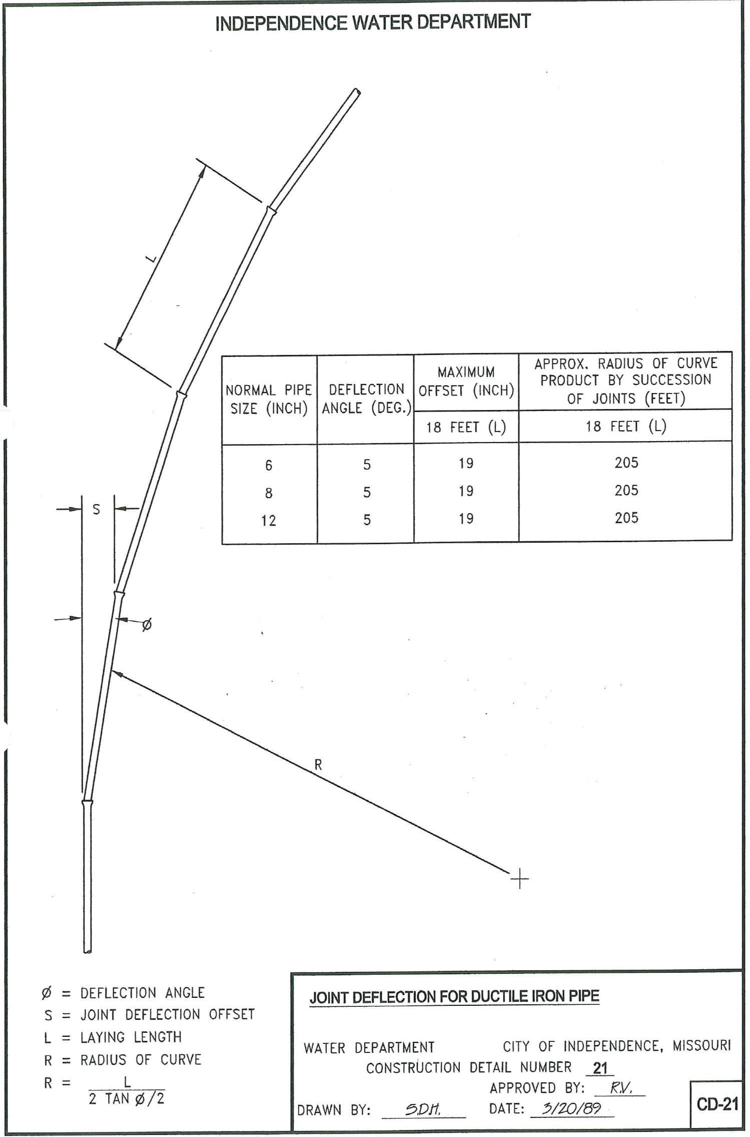
PM-2.01. Ductile Iron Pipe: All pipe and fittings to be incorporated into the City’s potable water system shall be ductile iron pipe with a maximum joint deflection of 5 degrees in accordance with the following specifications: Centrifugallycast ductileironpipe,withTytonjointscompletewithnecessarygaskets and lubricantinaccordancewithANSI/AWWASpecificationsC151/A21.51forductileironpipe. Pipewillbe furnished cement lined per ANSI/AWWA C104/A21.4, seal coated inside and bituminous coated outside. Nominal 18-foot lengths in quantity pipe class, and M.T., as shown below:
I. 6-inch Class 52 Tyton Joint Cast Ductile Iron pipe, .031" M.T.
II. 8-inch Class 52 Tyton Joint Cast Ductile Iron Pipe, 0.33" M.T.
III. 12-inch Class 52 Tyton Joint Cast Ductile Iron Pipe, 0.37" M.T.
Fittings are to be ductile-iron with Tyton joint per ANSI/AWWA C110/A21.10 specifications.
The Tyton joint shall conform in all respects to requirements for the push-on joint in ANSI/AWWA C111/A21.11 specifications.
All ductile-iron fittings to have a rated minimum working pressure of 350 psi M.T. and a maximum joint deflection of 5 degrees.
I. 6-inch Class 350 Tyton Joint Cast Ductile Iron, See Page 5a for M.T.
II. 8-inch Class 350 Tyton Joint Cast Ductile Iron, See Page 5a for M.T.
III. 12-inch Class 350 Tyton Joint Cast Ductile Iron, See Page 5a for M.T.
Outside coating: petroleum asphaltic coating approximately 1 mil in thickness.
Cement-mortar inside lining: cement lining in accordance with ANSI/AWWA C104/A21.4 Standard for Cement-Mortar Lining for Ductile Iron Fittings for Water. -5-
NOTE: All fittings are to be Trim Tyton® as manufactured by U.S. Pipe or approved equal. Coating and lining shall be Permafuse® epoxy applied at the manufacturing facility of the fitting. Permafuse® epoxy shall be NSF-61 approved.
All fittings and pipe shall be manufactured in the United States.
FITTING METAL THICKNESS FITTING SIZE 11 1/4° Min. M.T. 22 1/2° Min. M.T. 45° Min. M.T. 90° Min. M.T. 6” .37 .37 .37 .37 8” .39 .39 .39 .39 12” .43 .43 .43 .43
PIPELINE MATERIALS (Cont.)
-5A-
PIPELINE MATERIALS (Cont.)
Alternate coating and lining; ductile iron fittings may be coated with a 6-8 mil nominal thickness fusion bonded epoxy conforming to requirements of ANSI/AWWA C550 and C116/A21.16.
PM-3. POLYETHYLENE ENCASEMENT:
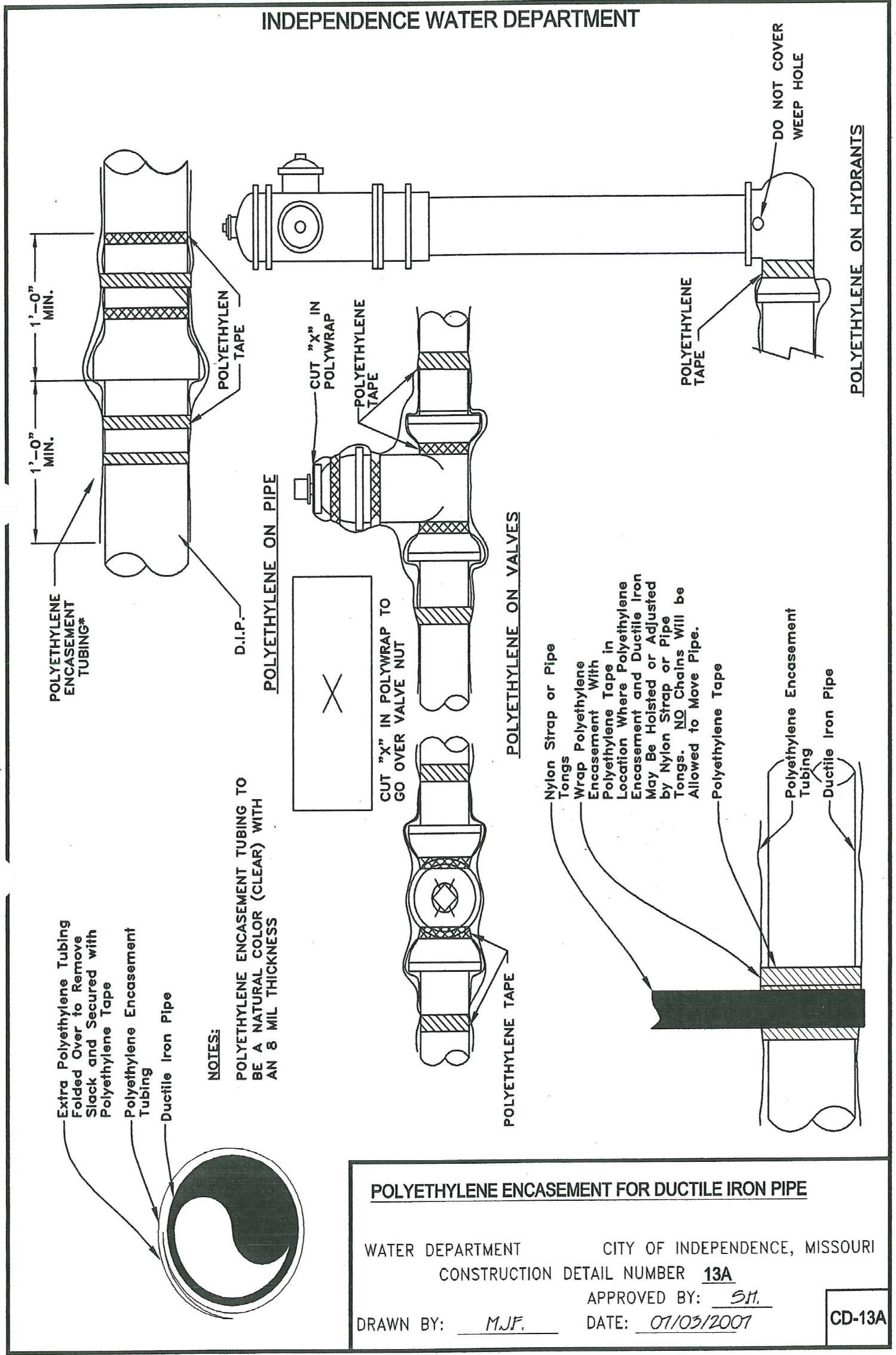
PM-3.01. PolyethyleneEncasement: Allductileironpipefittings,valves,andotherappurtenantitemsshall be encased in polyethylene material as specified in the polyethylene encasement specifications contained herein. Polyethylene encasement materials shall be:
20-INCH POLYWRAP (for 6-inch and 8-inch pipe)
Polyethylene encasement of Ductile Iron Pipe in accordance with ANSI/AWWA C105/A21.5. It shall be Flat 20-Inch and be a natural color (not black) with an 8 mil thickness. It shall be perforated at 20-foot intervals.
30-INCH POLYWRAP (for 12-inch pipe)
Polyethylene encasement of Ductile Iron Pipe in accordance with ANSI/AWWA C105/A21.5. It shall be Flat 30-Inch and be a natural color (not black) with an 8 mil thickness. It shall be perforated at 20-foot intervals.
PM-3.02. Adhesive tape shall be a general purpose adhesive tape 1-inch wide and approximately 8 mils thick, such as Scotchtape No. 50, Polyken No. 900, Tapecoat CT, or accepted equal.
PM-4. VALVES
PM-4.01. Gate Valves: The type, size, and location of valves shall be as shown on the accepted plans. Except as modified or provided herein, all gate valves in pipelines shall be 250 psi (pressure rating shall be cast on the outside of the valve), d.i. resilient-seated, tight closure gate valves, with non-rising stems, with TYTON© joint ends and name shall be cast on near the bell for recognition conforming with all applicable requirements of ANSI/AWWA C509 and C500.
PM-4.02. ValveCoating: Allinternalandexternalsurfacesshallbecoatedwithafusionbondedepoxytoa minimumthicknessof8mils. Saidcoatingshallbenon-toxic,impartnotastetowaterandshallconformto ANSI/AWWA C550. Said coating shall be applied prior to assembly such that all exposed external areas, including end connection bolt holes, body to bonnet bolt holes shall be coated with epoxy.
PM-4.03. Valve Gate: The gate shall consist of a ductile iron gate having a vulcanized synthetic rubber coating with no rubber-to-metal seams or edges to the waterway when in fully closed position. The gate shall provide zero leakage at the water working pressure in either direction.
-6-
MATERIALS (Cont.)
PM-4.04. Stainless Steel Bolts and Nuts: The bolts and nuts that fasten the bonnet shall be ANSI Type 34 or 316 stainless steel.
PM-4.05. ValveSeals: ThevalvesshallbeprovidedwithtwoO-ringstemseals,onelocatedaboveandone below the stem collar. The area between the O-rings shall be filled with lubricant. The “O” ring stem seal shall be replaceable with the valve under pressure in the full-open position.
One anti-friction washer shall be located below and one above the thrust collar. All seals between valve parts, such as body and bonnet and bonnet cover, shall be O-rings.
PM-4.06. Valve Operation: All valvesshall be equippedwith atwo-inch(2")square wrench nut and THE DIRECTION OF ROTATION TO OPEN THE VALVE SHALL BE TO THE LEFT (COUNTER CLOCKWISE).
PM-5. VALVE BOXES, BASES, LIDS, COVERS, AND VALVE STEM EXTENSION:
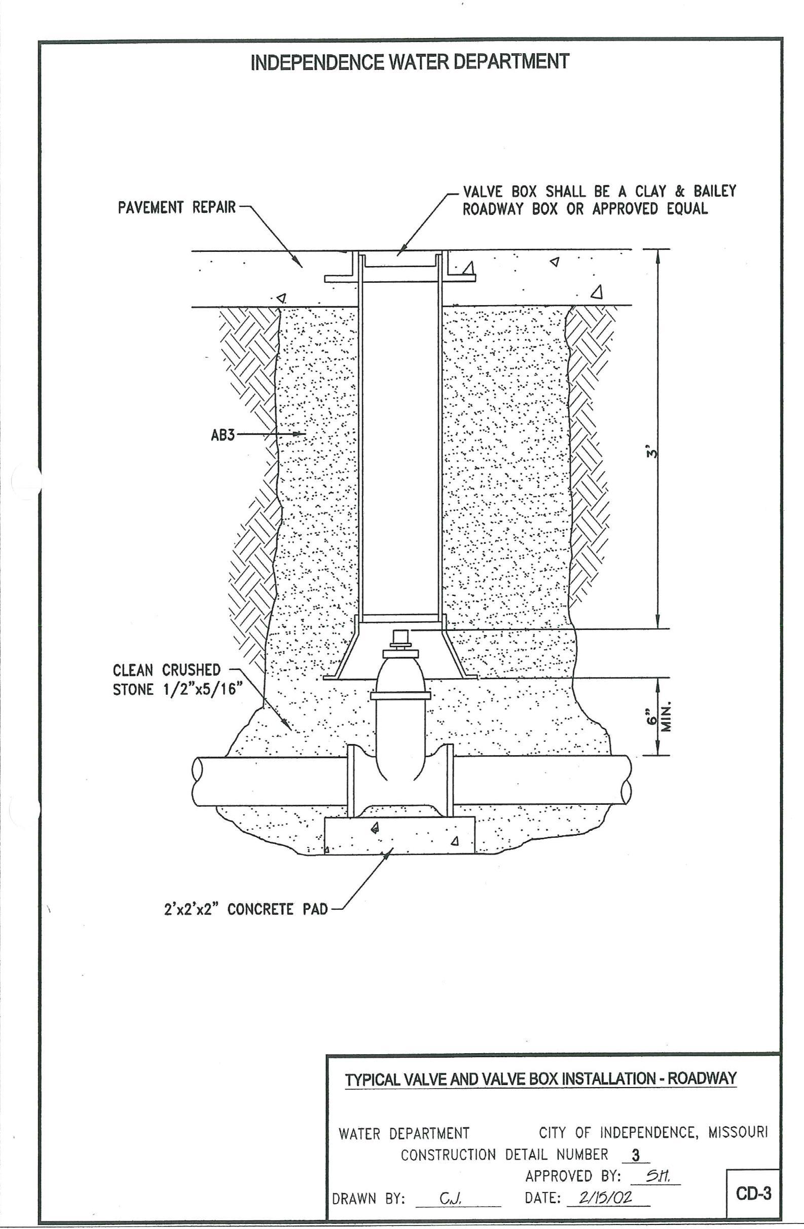
PM-5.01. ValveBoxes: Allvalveboxesshallbemadeofcastorductileiron,asmanufacturedbyClayand Bailey Manufacturing Company, or accepted equivalent. All roadway valve boxes shall consist of a base (no.2260-6),shaftsectionof6"diameterductileironpipe,topsectionandalidmarked“Water”(No.2196). Valve boxes for valves not in a roadway shall have a base, a minimum 4 1/4" diameter shaft with lid marked “Water” and consist of an adjustable slip or screw type two-piece valve box or a minimum 6” diameter PVC pipe SDR-26 with lid marked “Water” (no 2194). See Construction Detail CD-3 and CD-4 for installation requirements. A valve box trench adaptor may be used in place of the valve box.
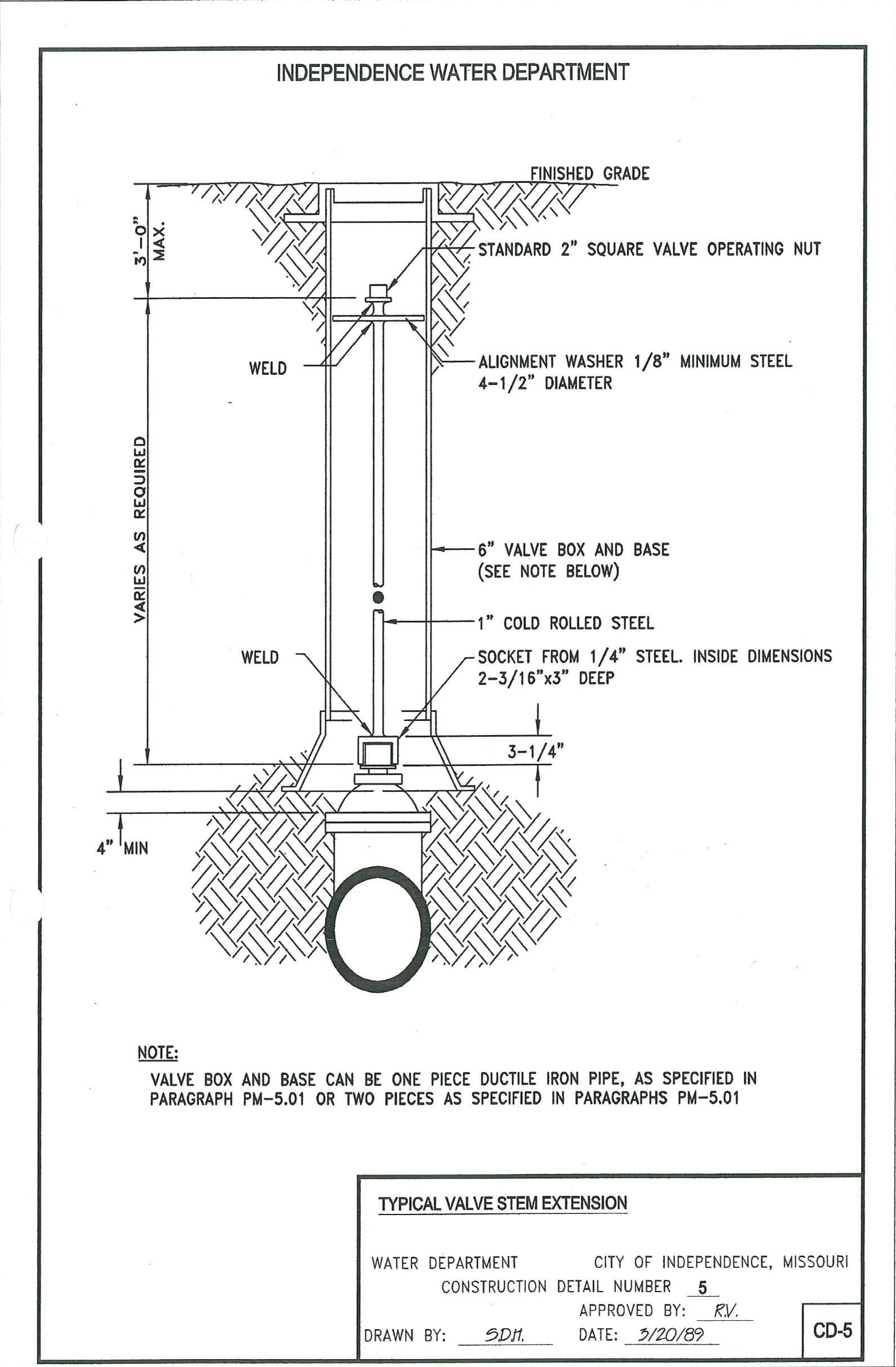
PM-5.02. ValveStem Extension: Whenthedistancefrom thetop ofthevalvecoverto thevalveoperating nut exceeds 3 feet, each buried valve shall be provided with an extension stem and operating nut. See Construction Detail CD-5 for installation requirements.
PM-6. FIRE HYDRANT: Fire hydrants shall conform to the requirements of AWWA Standard for DryBarrel Fire Hydrants (ANSI/AWWA C-502); and in addition, shall be listed by Underwriters Laboratories and Factory Mutual Research Corp. Cast marks or other permanent means shall be used to identify the fire hydrant as conforming to these standards.
Hydrantsshallberatedfor250psioperatingpressureandtestedat500psipersection5.1ofAWWAC502. Production testing of each hydrant shall be performed at 500 psi to ensure proper assembly and operation and detect any imperfections. All iron parts, as designated in section 3.1.2 of AWWA C/502, shall be ductile iron. Gray iron shall not be permitted, except for those parts which are designated to break upon traffic impact. The depth of bury shall be as stated on the drawings.
PIPELINE
-7-
PIPELINE MATERIALS (Cont.)
Nozzles shall have two 2-1/2" hoses 180⁰ apart and one 4-1/2" pumper. All nozzles shall be at same elevation. Nozzle threads shall be National Standard Fire Hose Coupling Screw Thread as described in Appendix A of AWWA C502. Nozzle caps shall be provided with chains and gaskets. Nozzles shall be reversed threaded into the upper barrel and mechanically locked into place.
Hydrantshallbe5-1/4"mainvalveopeningminimum,andshallbeofthefullcompressiondesign,opening andclosingwiththepressure. Themainvalveseat ringshallthreadintoabronzesubseatandallthegaskets sealingtheseatringshallbeonabronze-to-bronzeseatingsurface. Theseat ringthreadsshallnotserveasa pressure seal. The entire valve and rod assembly shall be removable by use of a small lightweight seat removal wrench.
The drain valves shall allow complete drainage of all residual water in the hydrant. The circumferential drain passage inside the hydrant shall be bronze on all surfaces.
All exterior bolting and fasteners below the ground line shall be stainless steel. Plated steel bolts and nuts are not acceptable.
Hydrant shall bethebreakawaytype,with afrangible ground lineandrodcouplingdesignedto break upon traffic impact and prevent further damage to the hydrant and connecting piping. The frangible coupling shall allow the upper section to be rotated to any desired position. Couplings which employ lugs, keeper devices, or a breakaway barrel are not acceptable. Frangible bolts are not acceptable either, due to the possibility of the use of non-frangible bolts.
Hydrant operating nuts shall be ductile iron and shall be pentagonal in shape, 1-1/2" point to flat (AWWA standard). The operating nut shall function as a weather shield. Hydrant shall open to the left.
The operating mechanisms shall utilize two “O” ring seals between the revolving nut and bronze-sheathed upper section of the valve rod. The top of the rod shall also be fitted with a travel stop nut to limit downward travel of the rod. All-weather grease shall be used to reduce friction in the thruster collar while opening the hydrant. The hydrant inlet shall be Tyton© Joint. Opening shall be 6 inches.
- Hydrant shall be painted orange with black nozzle caps and chain using Benjamin Moore & Co., Industrial Maint. Coating, Orange M22-65, Black M22-82.
- Manufacturer shall certify that hydrants furnished meet this specification.
- Fire hydrants shall be U.S. Pipe Metropolitan 250, American Darling or equal and approved
-8-
PIPELINE MATERIALS (Cont.)
PM-7 INSPECTION OF MATERIALS: The Contractor shall submit (prior to construction) complete literature, shop drawings, and manufacturer’s specifications on all material he proposes to furnish in connection with the Contract Agreement. Acceptance of such detailed information by the Engineering Supervisor will not release the Contractor of the responsibility for any error which may exist as the Contractorshall beresponsibleforthesatisfactorycompletionofall workwithinthelimits oftheContract. When required by theStandardsor by theEngineering Supervisor,theContractorshall furnish evidencein the form of test results or certificates that the material incorporated in the work conforms to the Standards.
All pipe,fittings, specials, valves,andothermaterials to beusedin the construction ofthewatermain shall be inspected by the Inspector prior to installation. The Contractor shall furnish any necessary labor or equipmentrequiredbytheInspectortocompletetheirinspection. Nopipe,fitting,specials,valves,orother material shall be placed until they have been inspected by the Inspector.
Inspection and conformance of the materials to this Standard will not relieve the Contractor of his subsequentresponsibilityregardingthematerials Anydefectivematerialsshallberemovedandreplacedby the Contractor at his own expense.
PM-8. THRUST RESTRAINTS:
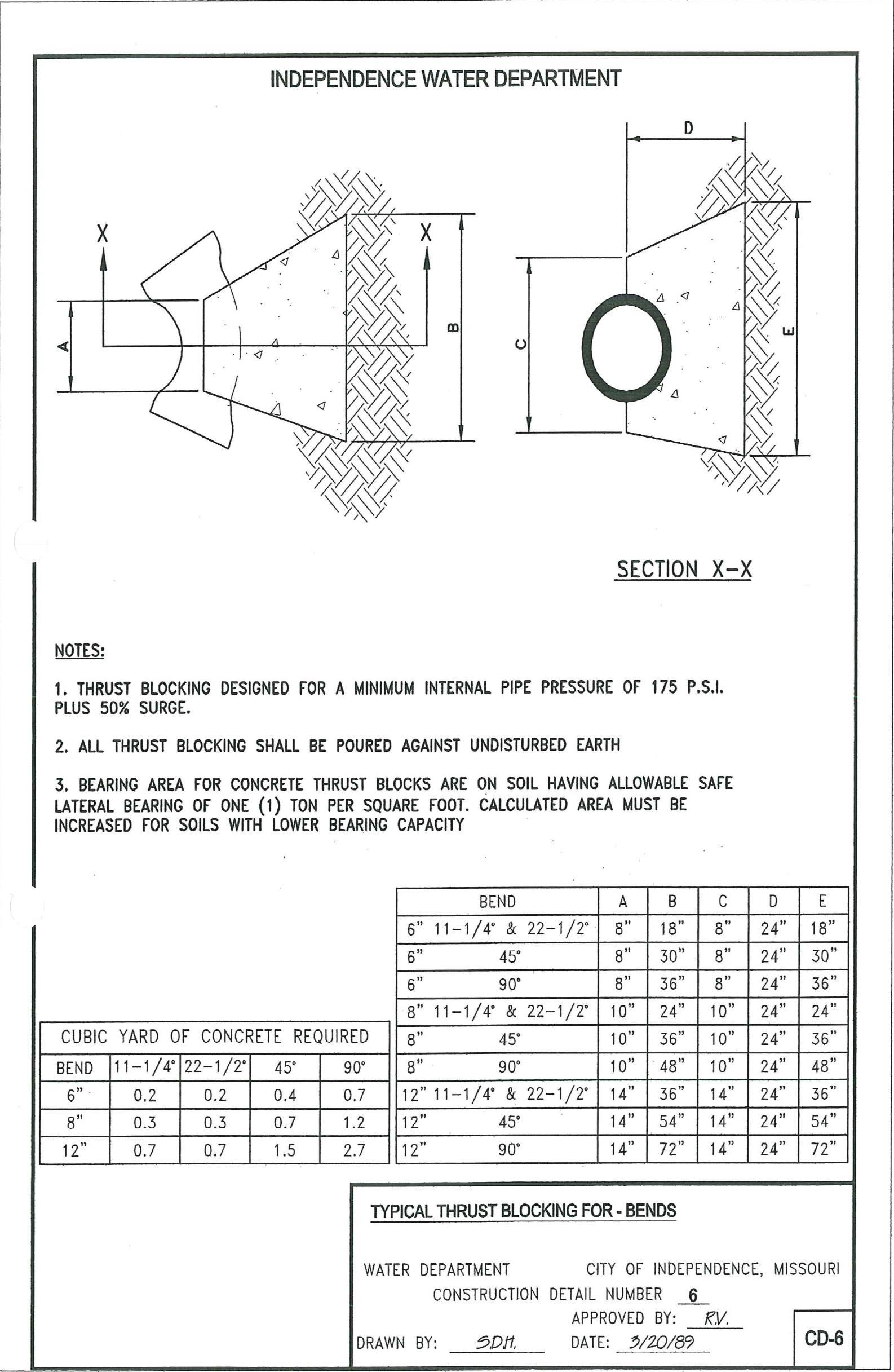
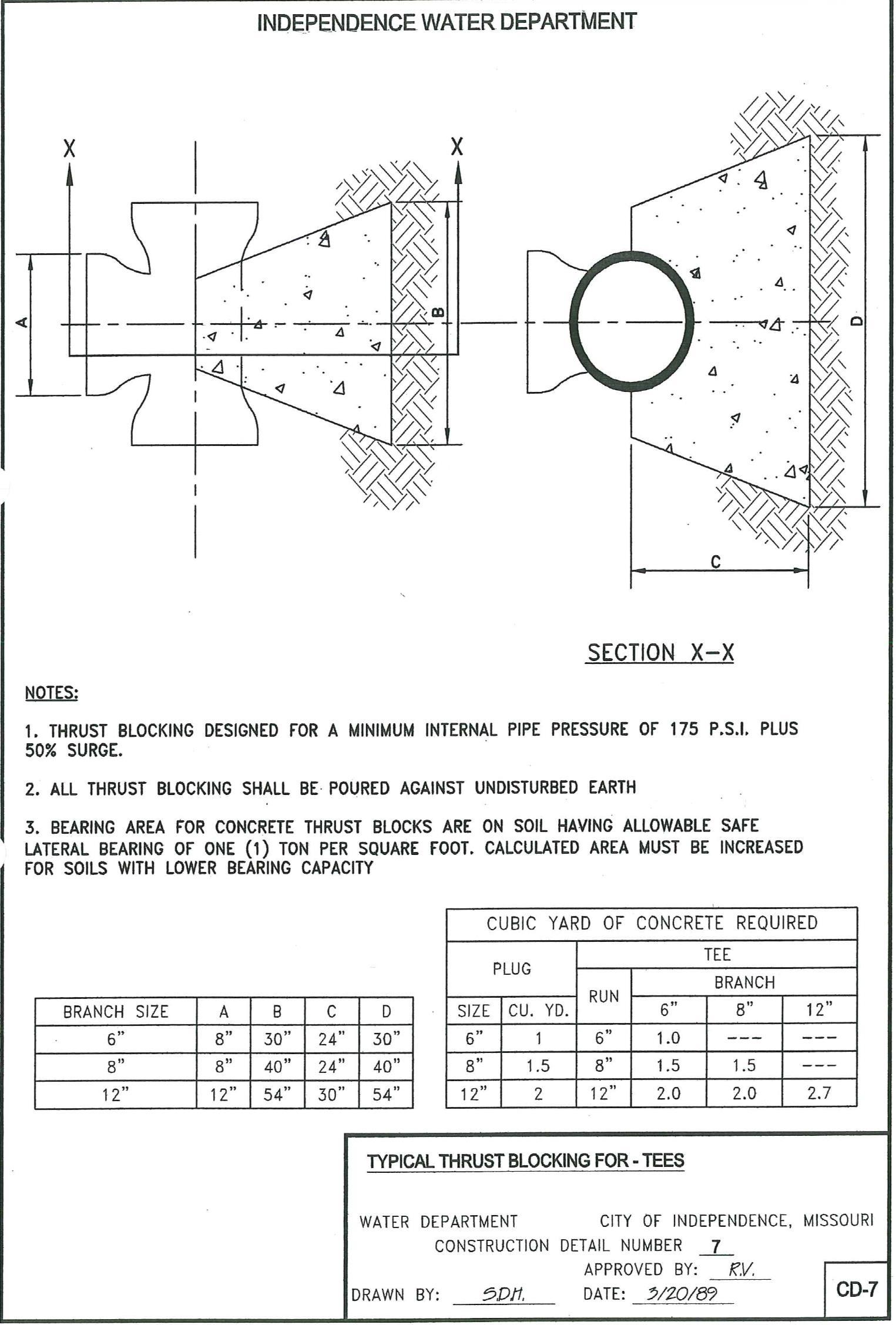
PM-8.01. Thrust Blocks: Thrust blocking shall be designed for a minimum internal pipe pressure of 175 pounds per square inch plus 50% surge. Concrete for thrust blocks shall have a twenty-eight (28) day compression strength of two thousand (2000) psi. The blocking shall be kept clear of the entire bell configuration of any adjacent joint and shall be poured against undisturbed earth. All thrust blocks shall meet the criteria found on Construction Details CD-6, CD-7 and CD-7A.
Bearingareas forconcretethrust block arebased onsoil having an allowablesafelateral bearingof one(1) ton per square foot. Calculated area must be increased for soils with lower bearing capacity.
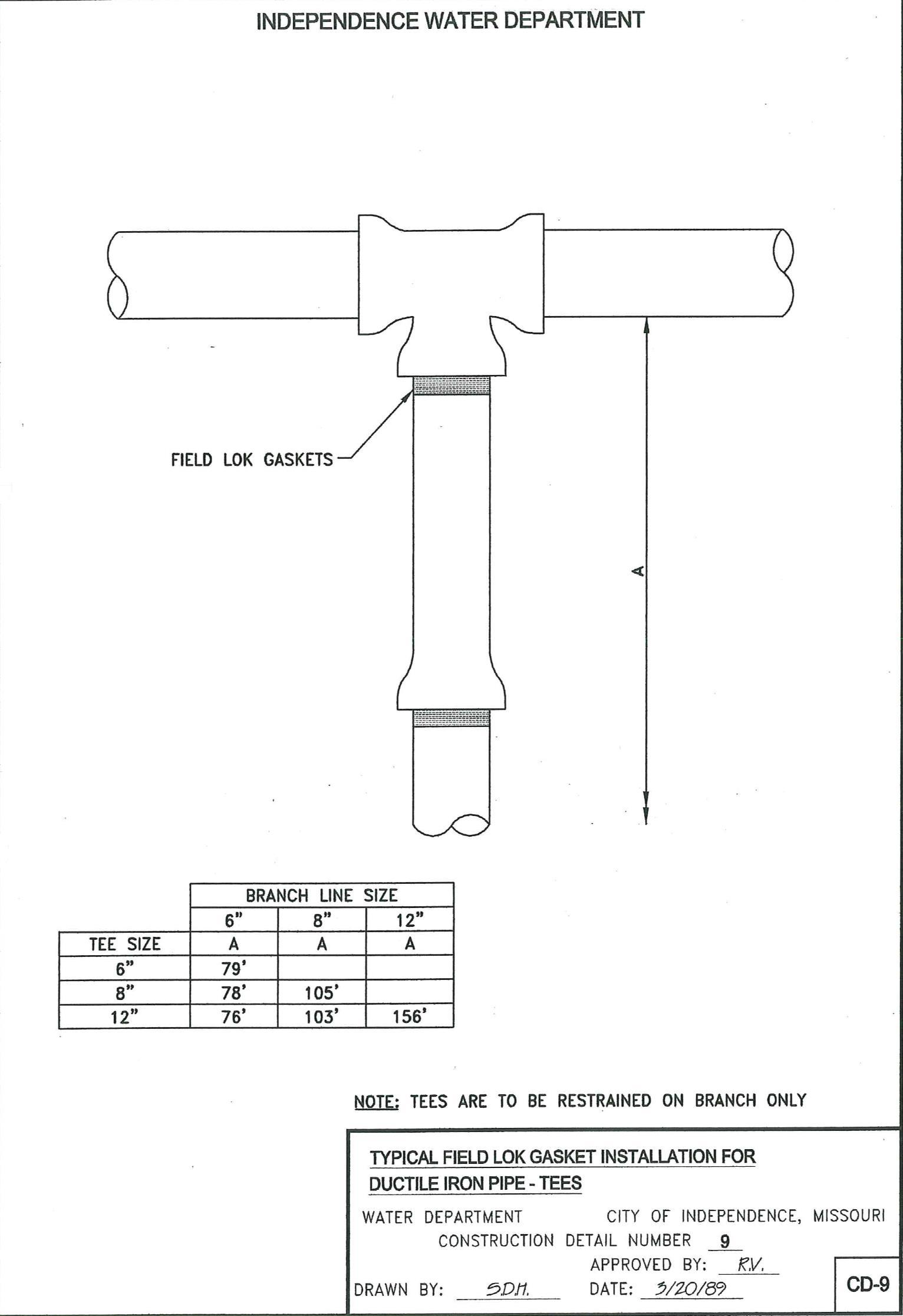
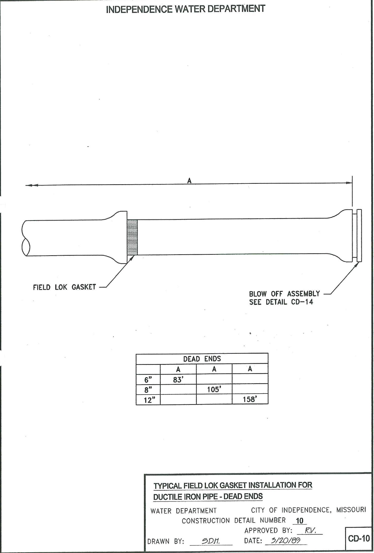
PM-8.02. Field Lok Gaskets: The use of Field Lok Gaskets 350® is acceptable in lieu of concrete thrust block restraint, provided they are manufactured by the U.S. Pipe and Foundry Company, and installed in accordance with the recommendations of the Ductile Iron Pipe Research Association, but no less than the lengths shown on Construction Details CD- 8, CD-9, and CD-10.
-9-
EXISTING UTILITIES AND IMPROVEMENTS
EU-1. LOCATION OF UNDERGROUND UTILITIES: The Contractor shall locate all underground utilitiesandotherobstacleswhichwillbeencounteredduringthecourseofconstruction;andlocationsshall beestablished beforeexcavationbypower-driven equipment. Destructionordamageto any utility suchas telephoneconduits,gasmainsandservices,watermains,valves,hydrantsandservices,electrical conduits, culverts, sewers, etc., shall be repaired or replaced at the expense of the Contractor.
EU-2. PROTECTIONOFPROPERTYANDEXISTINGIMPROVEMENTS: TheContractorshallprotect fromdamageorinjuryallexistingimprovements. Anysuchitemsinadvertentlydamagedshallbereplaced or repaired at the Contractor’s expense.
Water and gas mains, sanitary and storm sewers, telephone and electric power conduits and cables, and house drains and services shall be exposed in advance of excavation so that they may be protected against damage and so that minor changes in grade and alignment may be made.
If the Contractor desires the removal of an existing sewer, conduit, cable, tree, shrub, curb, or pavement to facilitate construction, such item not conflicting with the final location of the water main or appurtenances thereto,heshallapplytotheproperauthorityforpermissionforsuchtemporaryremovalwiththeexpressed understandingthatifsuchpermissionisgranted,all costsincurredin removingandreplacingtheitemshall be paid by the Contractor.

Adequate provision shall be made for the flow of sewers, drains, and water courses encountered during construction; and the structures which may have been disturbed shall be satisfactorily restored upon completion of the work.
Trees, fences, poles, guy wires and anchors, shrubs, flower beds, sod, and all other property shall be protected unless their removal is authorized; any property damaged shall be satisfactorily restored by the Contractor.
To protect persons from injury and to avoid property damage, adequate barricades, construction signs, and guardsasrequiredshallbeplacedandmaintainedduringtheprogressoftheconstructionworkanduntilitis safefortraffictousethetrenchedroadwayorwalkway. Wheneverrequired,watchmenshallbeprovidedto preventaccidents. Rulesandregulationsoflocalauthoritiesrespectingsafetyprovisionsshallbeobserved. -10-
EXISTING UTILITIES AND IMPROVEMENTS (Cont.)
EU-3. REMOVING AND RESTORING STREET PAVEMENT, DRIVEWAYS, AND OTHER SURFACEDAREAS: Thecontractorshallremoveandrestoreallstreetorroadwaypavement,driveways, surfaced parking areas and other surfaced or graveled areas wherever encountered in the laying of pipe, fittings, valves, hydrants, backing blocks, and other appurtenances. All excavation within public right-ofway requires a permit from the Public Works Department, 2nd Floor, City Hall (111 E. Maple) when in Independence, Missouri road right-of-way; Public Works Department, 2nd Floor Jackson County Court House Annex (306 W. Kansas) when in Jackson County, Missouri road right-of-way; and Permit Department,2ndFloor,MissouriHighwayandTransportationCommission(5117East31stStreet)whenin State right-of-way.
All pavement cuts in driveways, parking lots, streets, etc., shall be made with a concrete saw or with tools designedforcuttingthepavementwithaminimumofdamagetothesurroundingarea. Theedgesofallcuts shall be smooth and straight and shall be cut per the requirements of the governing authority.
Concrete pavement, asphaltic surface courses, macadam pavements, and any other type of pavement or surface course which is cut or damaged shall be restored to conform to, and as specified in, the “LAYING AND BACKFILL” section of these Standards.
Streets,highways,androadswhich,intheopinionofthegoverningauthority,mustbeopenedattheearliest possibletimetotrafficshallbebackfilledandthepavementrestoredimmediatelyafterthepipeand fittings are laid.
Driveways that are damaged or cut shall be restored equal in all respects to that which was removed. Allgraveledareas,orareasotherwisesurfacedforparkingorforanyotherreason,whicharecutordamaged in the construction shall be returned to a condition equal to that which existed before the construction. All materials used shall be of equal quality to the materials used in the original construction of the surface and shall be subject to the approval of the Owner or Developer.
EU-4. MAINTENANCEOFTRAFFIC:TheContractorshallconducthisworksoastointerfereaslittleas possiblewithpublictraffic,whethervehicularorpedestrian. Wherethrulanesoftrafficwillbeobstructed,a permit is required from the Transportation Department, 2nd Floor, City Hall (111 E. Maple) when in Independence, Missouri road right-of-way; Public Works Department, 2nd Floor, Jackson County Court House Annex (103 N. Main St.) when in Jackson County, Missouri road right-of-way; and Permit Department, 2nd Floor, Missouri Highway and Transportation Commission (600 NE Colbern Rd., Lee’s Summit, MO) when in State right-of-way. Whenever it is necessary to cross or interfere with roads, driveways,walks,whetherpublicorprivate,theContractorshall,athisownexpense,provideandmaintain suitable and safe bridges, detours, or other temporary expedients for the accommodation of public and private travel. He shall give reasonable notice to owners of private drives before interfering with them; provided however, that such maintenance of traffic will not be required at any point where the Contractor has obtained permission from the owner and tenant of private property, or from the authority having jurisdiction over public property involved, to obstruct traffic at any designated point thereon and for the duration of whatever period of time as may be agreed upon
-11-
EXCAVATION AND TRENCHING
EX-1. SCOPE: Excavation and trenching work shall include the necessary clearing, grubbing, and preparation of the site; removal and disposal of all debris; excavation and trenching as required; the handling,storage,transportation,anddisposalofallexcavatedmaterial;allnecessarysheeting,shoring,and protectionwork;preparationofsubgrades;pumpinganddewateringasnecessaryorrequired;protectionof adjacent property; and other appurtenant work.
Backfilling, pipe embedment, and surfacing and grading are covered in other portions of these Standards.
EX-2. GENERAL: Excavation and trenching work shall be performed in a safe and proper manner with suitable precautions being taken against all hazards and to provide adequate working space and clearances for the work to be performed therein.
The Contractor shall explore and expose any known or possible obstructions in advance of excavation for installation,forthepurposeofeliminatingabruptchangesingraderequiringtheinstallationofunnecessary fittings.
In paralleling present water and gas mains, the Contractor shall protect all service connections and shall arrange to furnish service to the consumers with a minimum of interruptions.

All excavated material shall be placed in a manner that will not endanger the work and that will avoid obstructing sidewalks and driveways. Gutters shall be kept clear or other satisfactory provisions made for street drainage. Subgrade surfaces shall be clean and free of loose material of any kind when concrete is placed thereon.
EX-3. BLASTING: Before any blasting is done within the City Limits of Independence, Missouri, the Contractor shall obtain a blasting permit from the City Engineer’s Office, 2nd Floor, City Hall (111 E. Maple) when in Independence, Missouri. No person may do the actual work of preparing, placing, and detonatingexplosivesunlesshepossessesablastingpermitissuedbytheCityEngineer. Theblastingpermit and license must be shown to the Water Department Inspector before any blasting work is done.
All existing safety regulations, laws, and ordinances on the storage, transportation, and use of explosives shall be enforced at all times.
Blasting will be permitted only when proper precautions are taken for the protection of persons, the work, private property, public utilities, and the public from damage or injury. Any damage done by blasting will be repaired by the Contractor at his own expense. -12-
EXCAVATION AND TRENCHING (Cont.)
TheContractorshall beliableforall injuries to ordeaths ofpersonsordamageto propertycausedby blasts or explosives.
EX-4. UNAUTHORIZED EXCAVATION: All material excavated below the bottom of concrete walls, footings, slabs on grade, and foundations shall be replaced by and at the expense of the Contractor with material as specified by the authority owning or having jurisdiction or control of said structures.
Any part of the trench excavated below grade shall be corrected with material accepted by the Water Department Inspector and placed and compacted by the Contractor.
EX-5. REMOVAL OF WATER: The Contractor shall provide and maintain adequate dewatering equipment to remove and dispose of all surface and ground water entering excavations, trenches, or other partsofthework. Eachexcavationshallbekeptdryduringsubgradepreparationandcontinuallythereafter untilthepipetobeinstalledisinstalled,totheextentthatnodamagefromhydrostaticpressure,flotation,or other cause will result.
All excavations for concrete structures or trenches which extend down to or below static ground water elevations shall be dewatered by lowering and maintaining the ground water surface beneath such excavations a distance of not less than twelve (12) inches below the bottom of the excavation.
Surface water shall be diverted or otherwise prevented from entering excavated areas or trenches to the greatest extent practicable without causing damage to adjacent property.
The Contractor will be held responsible for the condition of any pipe or conduit which he may use for drainage purposes, and all such pipes or conduits shall be left clean and free of sediment.
EX-6. SHEETING AND SHORING: General. Except where banks are cut back on a stable slope, excavation for trenches shall be properly and substantially sheeted, braced, and shored, as necessary to prevent caving or sliding to provide protection for workmen and work.
Specific - Reference must be made to:
Construction Industry Standards OSHA 2207
Part 1926 Occupational Safety and Health Standards
Subpart P Excavations, Trenching and Shoring
Sections 1926.650 through 1926.653
EX-7. STABILIZATION: Trench bottoms shall be firm, dense, and thoroughly compacted and consolidated; shall be free from mud and muck; and shall be sufficiently stable to remain firm and intact under the feet of the workmen.
Trench bottoms which are otherwise solid but which become mucky on top due to construction operations shall be reinforced with one or more layers of crushed stone or gravel. Not more than ½ inch depth of mud or muck shall be allowed to remain on stabilized trench bottoms when the pipe bedding material is placed thereon.
-13-
EXCAVATION AND TRENCHING (Cont.)
EX-8. TRENCH EXCAVATION: The Contractor shall not open more trench in advance of pipe laying than is necessary to expedite the work. One block or 300 feet (whichever is the shorter) shall be the maximumlengthofopentrenchaheadofpipelayingunlessbywrittenpermissionoftheWaterDepartment Inspector.
Except where tunneling is specified on the Construction Plans or by the Water Department, all trench excavations shall be open cut from the surface.
All excavations shall conform to the regulations set forth in the Traffic Code of the City of Independence, Missouri, or governing authority, and shall be protected with adequate lights and barricades.
EX-8.01. Alignment and Grade: The Engineer shall establish lines and grades to govern construction by settingoffsetstakesevery50feet(25feetoncurves)andoffsetstakeswithhubelevationsateachfittingand appurtenance, such as tee, bend, valve, fire hydrant, etc. Offset stakes are required and shall be marked to indicatetheoffset and cuts. Truecopies of“cut”notesshall befurnished bytheEngineer to theContractor and to the Water Department Inspector before construction begins.
The Engineer will notify the Water Department, Division of Engineering, one (1) day prior to staking the project for construction.
Vertical and horizontal alignment of pipes and the maximum joint deflection used in connection therewith shall be in conformity and as specified in the “LAYING AND BACKFILL” section of these Standards.
When possible, stakes shall beset to locate anyunderground utilities thatmayconflict withthe water main construction. However,inallcases,theContractorshallbegovernedbythesectionoftheStandardsentitled “EXISTING UTILITIES AND IMPROVEMENTS”.
It shall be the Contractor’s responsibility to transfer the alignment and grades to the bottom of the pipeline trench.
The Contractor must maintain a constant check of the pipe alignment and trench depth and will be held responsible for any deviations therefrom.
-14-
EXCAVATION AND TRENCHING (Cont.)
Unless otherwise shown or indicated on the plans or unless otherwise set forth by the Engineering Supervisor, the horizontal and vertical alignment of the water main shall be maintained to within the following tolerances:
HORIZONTAL VERTICAL
3" ±
42" to 48" Depth of Cover
EX-8.02. Minimum Cover: Except where otherwise shown, trenches shall be excavated to a depth sufficienttoprovideaminimumdepthofbackfillcoveroverthetopofthepipe,asindicatedabove. Greater pipe cover depths may be necessary on vertical curves or to provide necessary clearance beneath existing pipes, conduits, drains, drainage structures, or other obstructions encountered at normal pipe grades.
Measurement of pipe cover depth shall be made vertically from the outside top of pipe to final ground or pavement surface elevation.
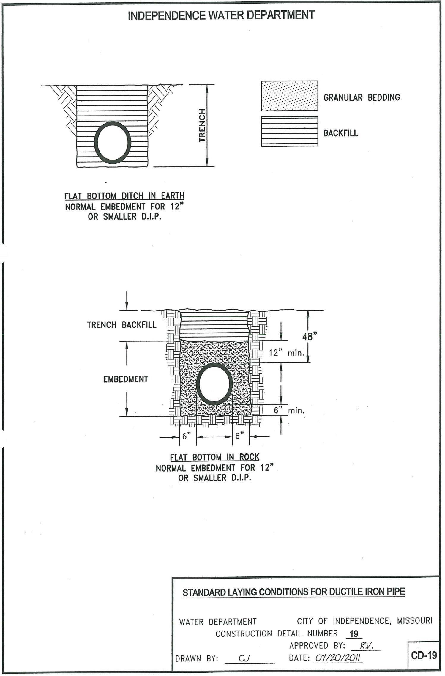
EX-8.03. Limiting Trench Width: Trenches shall be excavated to a width which will provide adequate working space and pipe clearances for proper pipe installation, jointing, and embedment. However, the limiting trench widths below an elevation six (6) inches above the top of the installed pipe shall be as follows:
EX-8.04. Trench Bottom in Earth: The trench in earth shall have a flat bottom the full width of the trench and shall be excavated to the grade to which the pipe is to be laid. The surface shall be graded to provide a uniform bearing and continuous support for each pipe at every point along its entire length.
Pipe Size Minimum Trench Width in Earth Maximum Trench Width in Earth Minimum Trench Width in Rock Maximum Trench Width in Rock Ductile Iron Pipe 6" 24" 30" 24" 30" 8" 26" 32" 24" 32" 12" 28" 34" 28" 36"
-15-
EXCAVATION AND TRENCHING (Cont.)
EX-8.05 Trench Bottoms in Rock: All rock excavation shall be carried to a minimum of six (6) inches below the bottom of the pipe. Granular pipe embedment material, as specified in the “LAYING AND BACKFILL”sectionoftheseStandardsandalsoas showninConstructionDetailCD-19,“StandardLaying Conditions for Ductile Iron Pipe".
EX-8.06. TrenchGrade: If,afterplacingthepipeinthetrench,itisfoundthepreparedtrenchbottomisnot attheproperelevation,thepipeshallberemovedandthegradecorrected. In nocaseshallthepipeberaised from and dropped on the trench bottom for the purpose of lowering a subgrade which is too high.
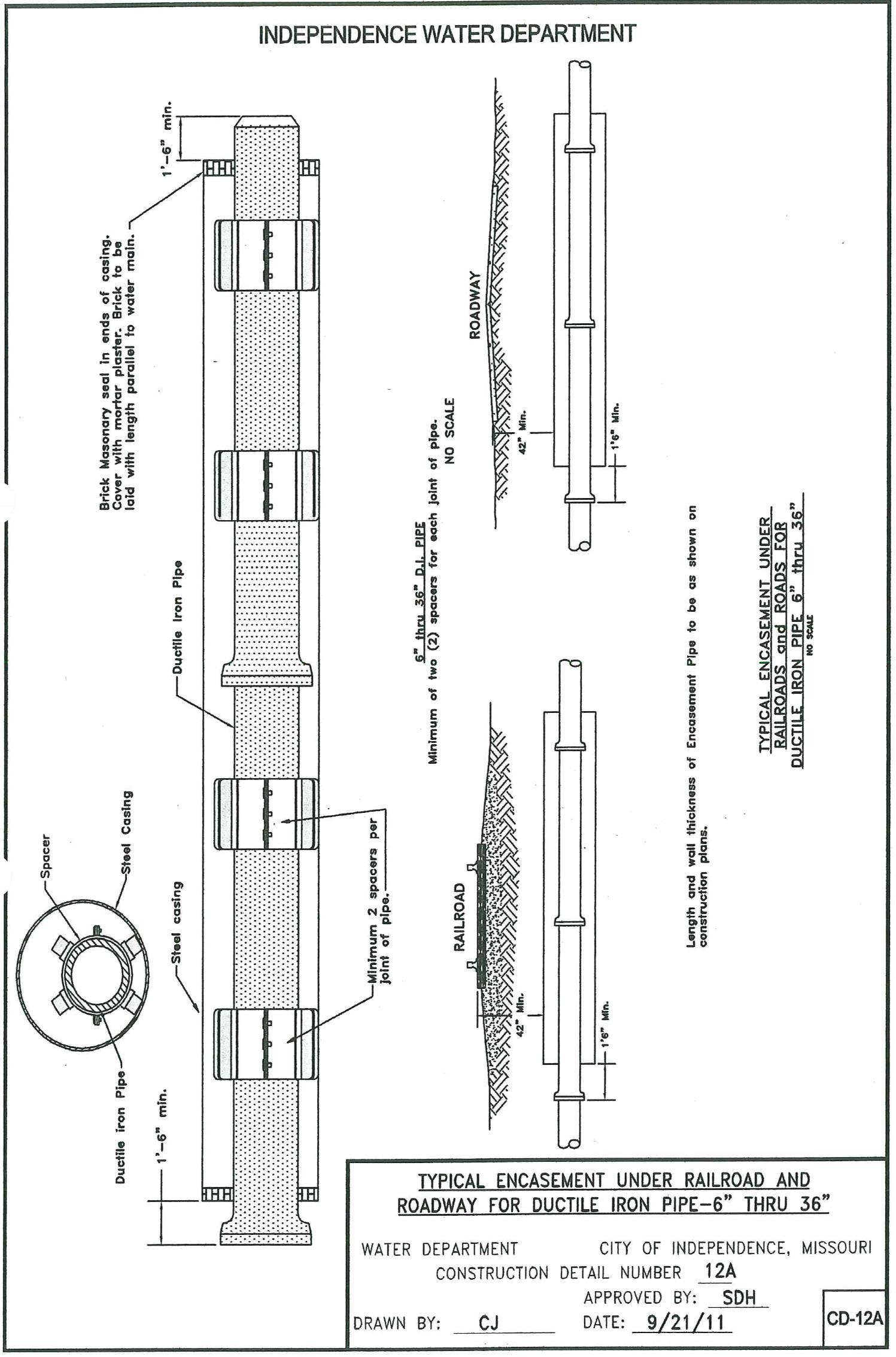
EX-9. HIGHWAY AND RAILROAD CROSSING: The Contractor shall make highway and railroad crossings in accordance with these Standards and as shown in Construction Detail CD-12, “Typical Encasement Under Railroads for Ductile Iron Pipe” .
All construction or work performed and all operations of the Contractor, his employees, or his subcontractors within the limits of highway or railroad right-of-ways shall be in conformity with all the requirements and regulations of the authority owning or having jurisdiction over the right-of-way in each case.
The Contractor shall pay fees and obtain permits to make the crossings unless otherwise directed.
EX-10. EXPEDITED CROSSINGS: The installation of crossings for streets, driveways, obstructions, or any other purpose to facilitate the construction or development of projects prior to the actual installation of watermainsisprohibitedunlesspriorapprovalisgrantedandallmaterialandinstallationsareinspectedand approved.
EX-11. BARRICADES ANDWARNINGSIGNS: TheContractor shall provideandmaintainin placeall barricades, warning signs, lights, and other safety devices required to protect the work, divert traffic, and warnthegeneralpublicofopenexcavations,unfilledtrenches,andotherareasorconditionswhichmightbe hazardous or dangerous during the daytime or at night.
-16-
LAYING AND BACKFILL
LB-1. PIPE INSTALLATION:
LB-1.01. Handling: Pipe,fittings,andaccessories shallbehandledinamannerthatwillinsureinstallation inasound,undamagedcondition. Equipment,tools,andmethodsusedinunloading,reloading,hauling,and laying pipe and fittings shall be such that the pipe, pipe coating, and fittings are not damaged. Hooks shall not be used. Under no circumstances shall pipe or accessories be dropped or dumped.
Pipe and fittings on which the cement lining has been broken or loosened shall be replaced by the Contractor.
All pipe coating which has been damaged shall be repaired by the Contractor before installing the pipe.
LB-1.02. Cutting Pipe: Ductile iron pipe shall be cut with either a saw or an abrasive wheel.
The cutting of pipe with a torch will not be permitted.
Cutting shall be done in a neat manner without damage to the pipe, or the cement lining. Cuts shall be smooth,straight,andatrightanglestothepipeaxis. Aftercutting,theendofthepipeshallbebeveled. The bevel will be a minimum of 1/4-inch wide at an angle of 30 degrees.
LB-1.03. Cleaning: Theinteriorofallpipeandfittingsshallbethoroughlycleanedofforeignmatterbefore being installed and shall be kept clean until the work has been accepted. Such surfaces shall be wire brushed, if necessary, wiped clean, and kept clean until jointing is completed.
LB-1.04. Inspection: Pipeandfittingsshallbecarefullyexaminedforcracksandotherdefectsimmediately beforeinstallation. Spigot ends shall beexamined with particularcaresince theyarevulnerable to damage from handling. All defective, damaged, or unsound pipe and fittings shall be rejected and marked as such and removed from the site of the work.
LB-1.05. AlignmentofBellandSpigotPipe: Pipelinesorrunsintendedtobestraightshallbelaidstraight. Deflections from a straight line or grade shall not exceed the quantities stipulated in Table 4 of ANSI/AWWA C600. (See Construction Detail CD-21.)
Either shorter pipe sections (not less than 4 feet in length) or special bends shall be installed where the alignment or grade requires them.

-17-
LAYING AND BACKFILL (Cont.)
LB-1.06. Laying Pipe: Pipe shall be protected from lateral displacement by pipe embedment material installed, as specified for “Pipe Embedment” (see Construction Detail CD-19). Under no circumstances shall the pipe be laid in water; and no pipe shall be laid under unsuitable trench conditions. (See EX-7. STABILIZATION).
Pipeshall belaid withthebell ends facing thedirectionoflayingexcept when reverselayingis specifically authorized by the Inspector.
Whenever pipelaying is stopped,theopen endof thelineshall be sealed witha watertight plug which will prevent trench water from entering the pipe.
The pipe is to be installed inside a tunnel liner in accordance with these Standards and as shown in Construction Detail CD-11 “Typical Encasement Under Roadways for Ductile Iron Pipe” and in ConstructionDetailCD-12“TypicalEncasementUnderRailroadsforDuctileIronPipe.” Theendsofeach tunnel liner shall be closed with a dry brick wall.
LB-1.07. TrenchBackfilling: Afterthepipesandjointshavebeeninspected,thetrenchshallbefilledwith selectedmaterialfreeofrockinthefollowingmannerwhenrequiredbytheInspector: Thematerialshallbe carefully placed and tamped under the bell of the pipe to insure a uniform bearing surface and to prevent lateralmovementofthepipe,thencarefullyplaced untilthefillreachestheone(1)footdepthoverthetopof the pipe. The remainder of the backfill shall be made by placing the excavated material back in the trench and compacting by a method approved by the local governing authority. Note: No rocks larger than grapefruit size will be allowed in backfill and at no time will there be over 100 lineal feet of pipe left exposed to the atmosphere.
LB-1.08. Rock Excavation: When the excavation is made through rock or other material too hard to be readilyremovedforadmittingthebellofthepipe,thetrenchshallbeexcavatedatleastsix(6)inchesdeeper thanthegradeoftheoutsidebottom ofthepipe,andrefilledwith ½" x5/16"clean crushed stone. Afterthe pipe has been installed ½" x 5/16" clean crushed stone will be placed one (1) foot above the pipe.
LB-1.09. Freezing Weather Backfilling: Backfilling during freezing weather shall not be done except by permission of the Inspector. No backfill materials shall be placed on frozen surfaces, nor shall frozen materials, snow, or ice be placed in any backfill.
LB-1.10. Push-On Joints: In the case of the push-on joint, the gasket seat in the bell shall be wiped clean withaclothafterwhichthegasketshouldbesprungintoplace. Thereafter,athinfilmoflubricantshouldbe applied to all of the inner surface of the gasket which will come into contact with the entering pipe.
The lubricant and the gaskets shall be as recommended and supplied by the manufacturer of the pipe being used. Thelubricantshallbeodorless,tasteless,andshallbenon-toxic,suitableforuseinpotablewater,and shall be water soluble.
-18-
LAYING AND BACKFILL (Cont.)
The plain end of the pipe shall be wiped clean and a thin film of lubricant shall be applied to the outside of the plain end of the pipe and its beveled edge. The plain end of the pipe should then be placed in approximate alignment with the bell of the pipe to which it is to be joined. The joint can be made up with theentering pipe deflectedat an angle,but this angleshouldnot exceedthe recommendedmaximum ofthe manufacturer. The plain end of the pipe should then be lifted and started into the socket so that it is in contact with the gasket.
The joint is made up by exerting sufficient force on the entering pipe so that its plain end is moved past the gasket (which is thereby compressed) until it makes contact with the base of the socket of the bell. This force can be applied by means of a jack type tool, backhoe, or other methods as approved by the Inspector
LB-1.11. Restrained Joints: Restrained joints shall be installed in strict accordance with Construction Details CD-6, CD-7, CD-7A, CD-8, CD-9 and CD-10.
LB-1.12. Couplings: Mechanical couplings and flanged coupling adapters shall be carefully installed in strictaccordancewiththemanufacturer’srecommendations. Theendsofpipecouplingsshallbeclean and smooth.
LB-2. POLYETHYLENE ENCASEMENT:
LB-2.01. General: Polyethylene encasement shall be installed on all ductile iron pipe and fittings Although not intended to be a completely air and water-tight enclosure, the polyethylene shall prevent contact between the pipe and the surrounding backfill.
LB-2.02. Installation: The polyethylene encasement shall be installed as specified in “Method A” or “MethodB”belowandas shownonConstructionDetail CD-13“PolyethyleneEncasementforDuctileIron Pipe.”
Method A: Polyethylene tubing shall be approximately two (2) feet longer than the length of the pipe section to provide a one (1) foot overlap on each adjacent pipe section. Tube ends are required to be taped in place.
Repairanyrips,punctures,orotherdamagestothepolyethylenewithadhesivetapeorwithashortlengthof polyethylene tube cut open, wrapped around the pipe, and secured with adhesive tape.
Method B: Polyethylene tubing shall beone (1) foot shorterthan thelength ofthe pipe sectionwith a three (3) foot length of polyethylene tube centered over pipe joint and lapped over pipe section and its tubing. Tube ends are required to be taped in place.
Repair any rips, punctures or other damage to the polyethylene, as described in Method A.
-19-
LAYING AND BACKFILL (Cont.)
LB-2.03. Pipe-ShapedAppurtenances: Bends,reducers,offsets,andanyotherpipe-shapedappurtenances shall be covered with polyethylene in the same manner as the pipe.
LB-2.04. Odd-shaped Appurtenances: Valves, tees, crosses, and other odd-shaped pieces which cannot practically bewrappedin atubeshall bewrappedwith aflat sheet or split length ofpolyethylenetube. The sheet shall be passed under the appurtenance and brought up around the body. Seams shall be made by bringing the edges together, folding over twice, and taping down. Tape polyethylene securely in place at overlaps, valve stems, and other penetrations.
LB-2.05. Openings in Encasement: Openings for branches, servicetaps, blow-offs, airvalves, andsimilar appurtenancesshallbemadebymakinganx-shapedcutinthepolyethyleneandtemporarilyfoldingthefilm back. After the appurtenance is installed, tape the slack securely to the appurtenance and repair the cut as well as any other damaged areas in the polyethylene with tape.
LB-3. SETTINGVALVESANDFITTINGS: Allvalvesandfittingsshallbesetandjointedinthemanner heretoforespecifiedforcleaning,laying,andjointingpipe. Thevalvesshallbesetverticalinthehorizontal pipeline. Cast iron valve covers and lids shall be installed by the Contractor and shall be supported and maintained, centered and plumb over the operating nut of the valve with the cover flush with the surface of the roadway or final grade. See Construction Details CD-3, CD-4, and CD-5.
Each valve shall be inspected before installation to insure that all foreign substances have been removed from within the valve body, and shall be opened and closed to see that all parts are in first-class working condition.
Valve boxes and valve bases shall be installed on all valves. Valve box trench adaptors may be used.
Allbendsandteesshallbeprovidedwithadequatethrustblockingorrestraintjoint. Thisthrustblockingor restrainedjoint shall beofplainconcreteorfield lok gaskets, as specified,andas calledforin Construction Details CD-6, CD-7, CD-8, CD-9, and CD-10.
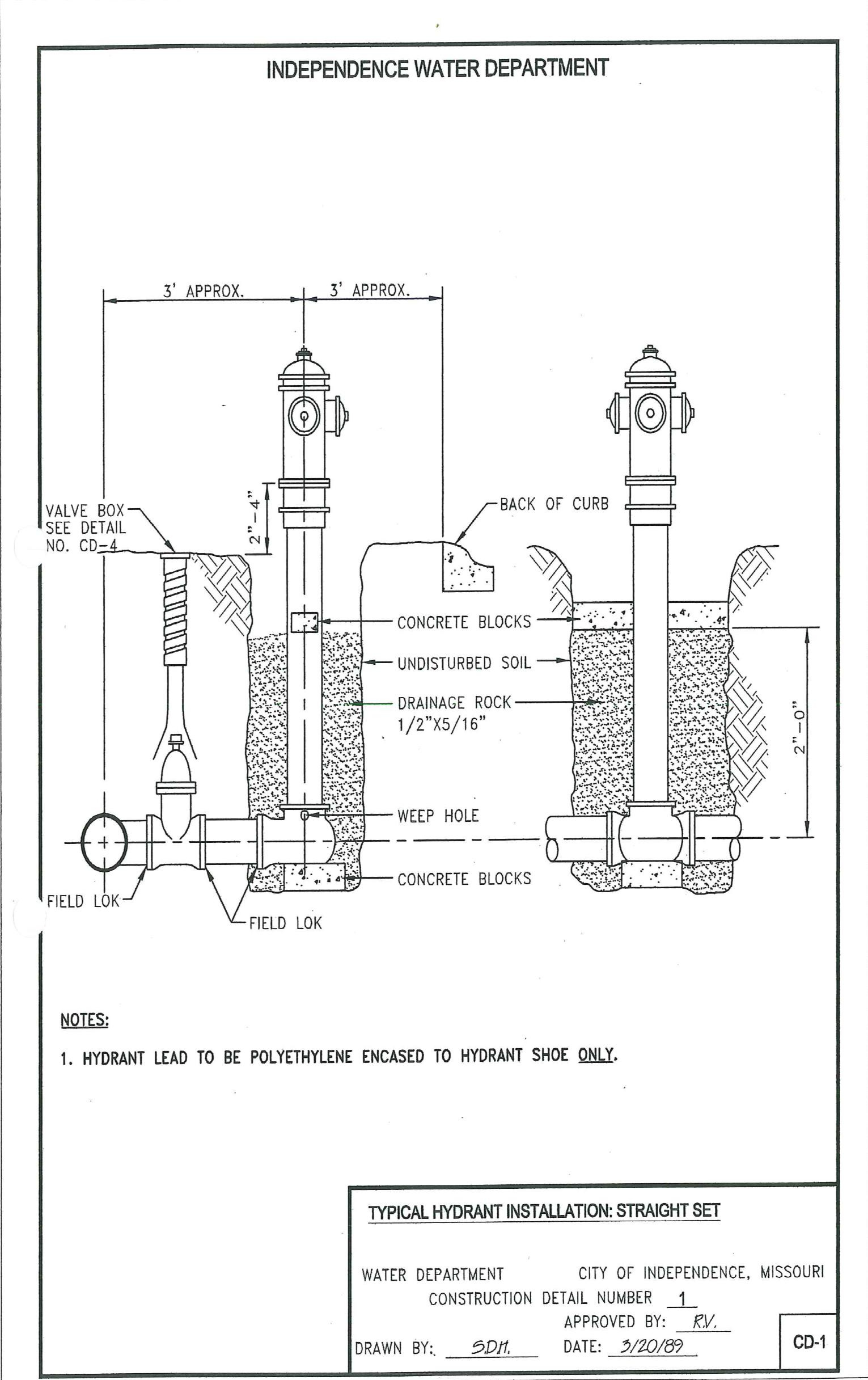
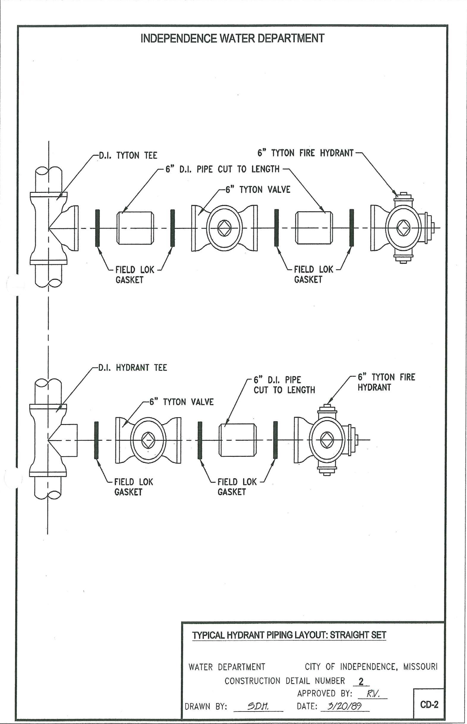
LB-4. SETTING FIRE HYDRANTS: All new hydrant installations shall be as shown in the Construction Details CD-1 and CD-2 and shall include all necessary excavation and backfill to make the installation complete. Hydrant lead to be polyethylene encased to hydrant shoe only
TheweepholesshownonConstructionDetail CD-1ofthehydrantshallbekeptclearandfreetodrain. All hydrants shall stand plumb and when placed behind curbs, the centerline of the hydrant shall be at least twenty-four (24) inches to thirty-six (36) inches from the back of the curb
In general, the hydrants shall be rotated so as to have the nozzle facing the street. Special circumstances may require otherwise, as determined by the Inspector.
-20-
LAYING AND BACKFILL (Cont.)
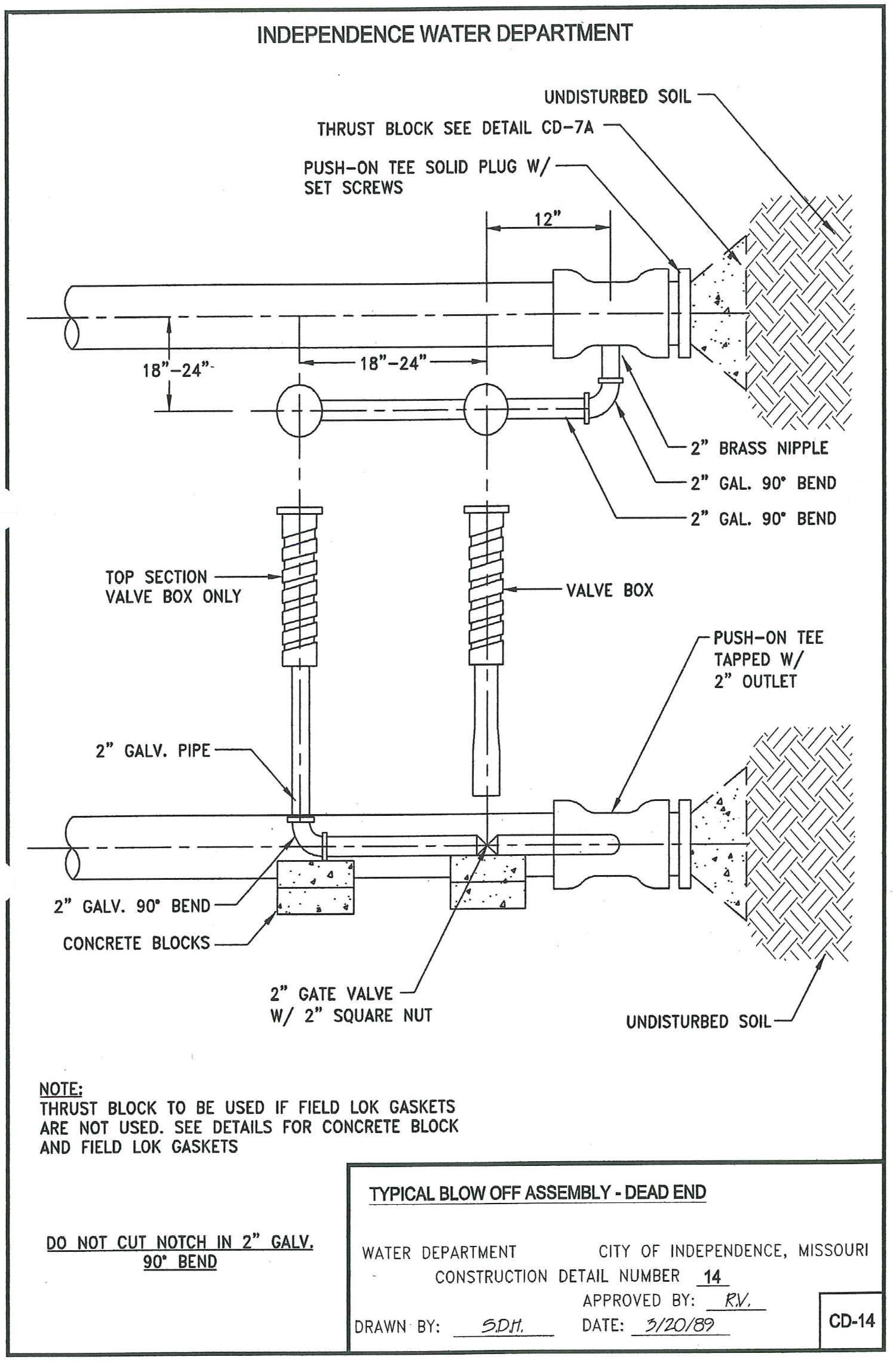
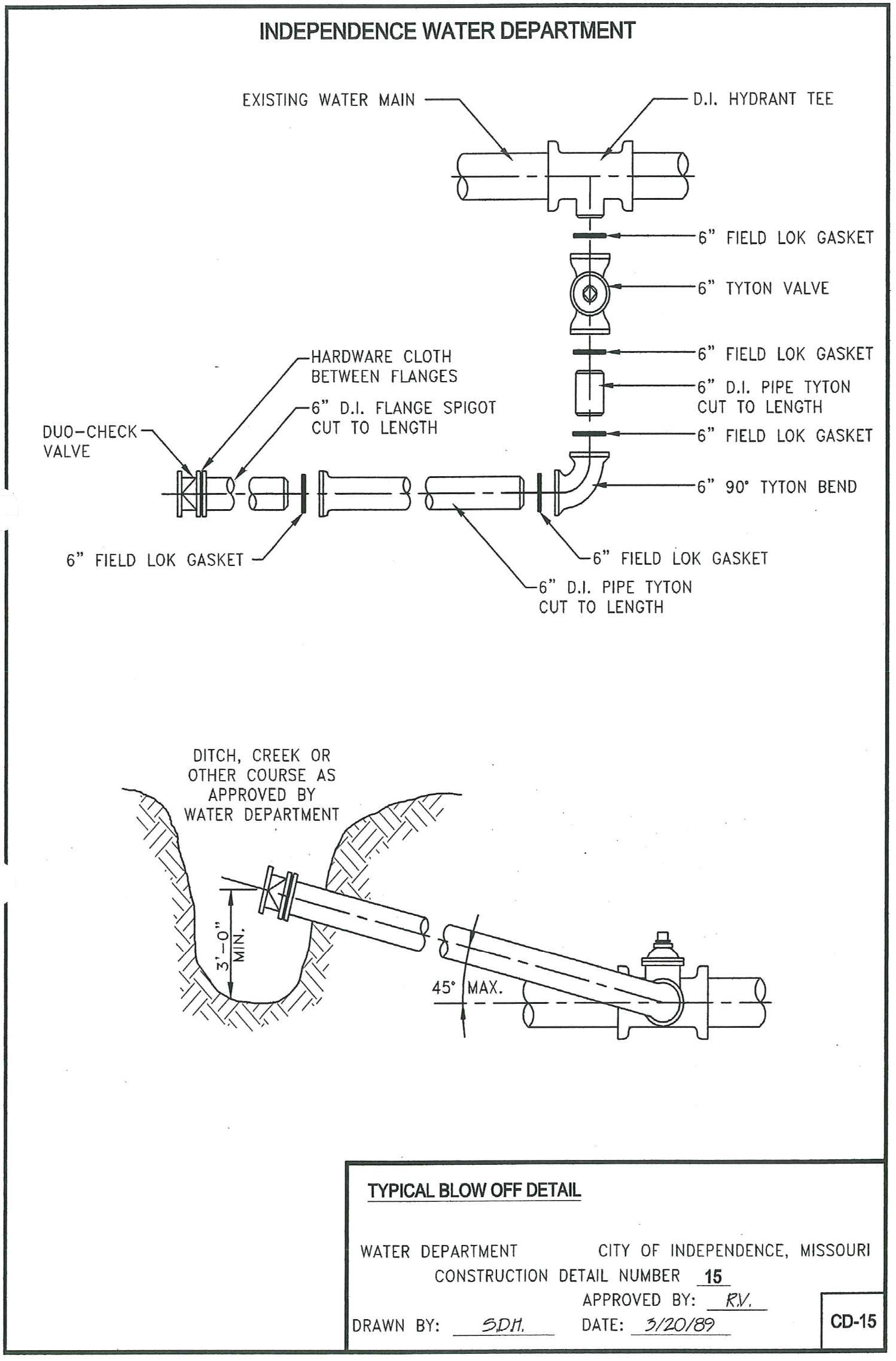
LB-5. BLOWOFF ASSEMBLIES: Blow-off Assemblies shall be provided at the locations and in the arrangement shown on the drawings and in conformity with Construction Details CD-14 and CD-15.
The TYTON joint plug shall be drilled and tapped for 2-inch standard pipe threads.
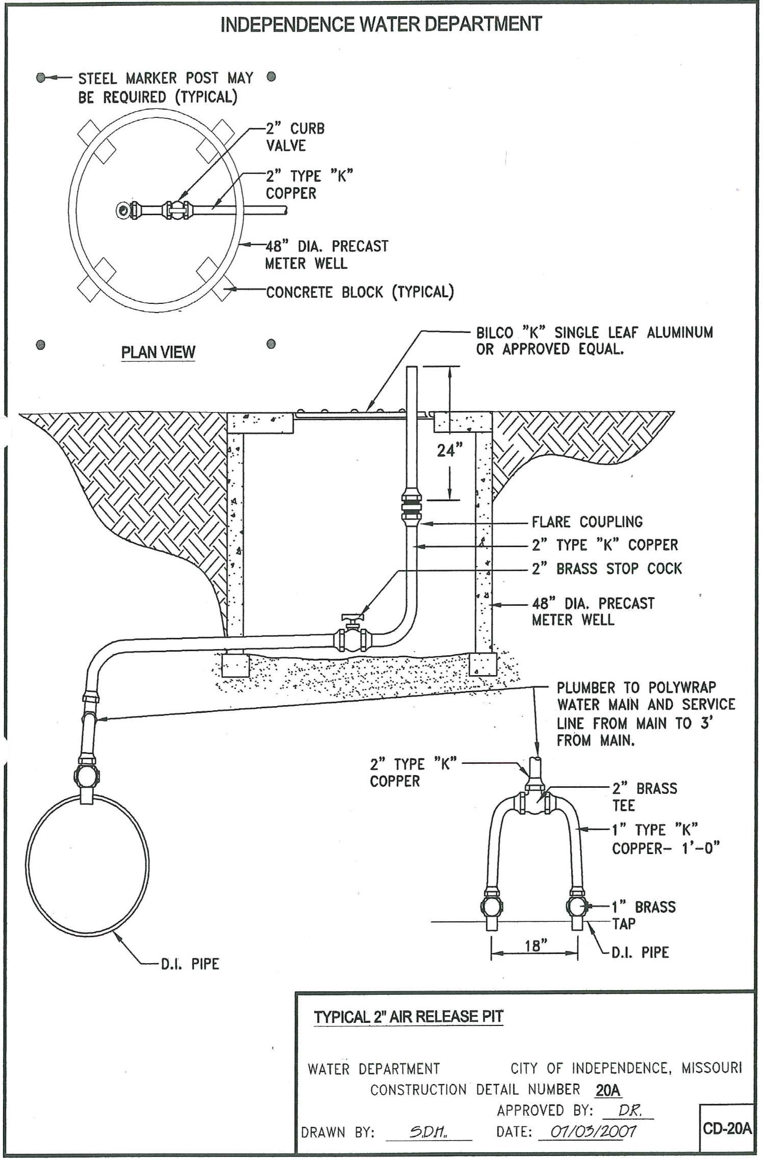
LB-6. AIRRELEASEASSEMBLIES: AirReleaseAssembliesshallbeprovidedatthelocationsandinthe arrangement shown on the drawings and in conformity with Construction Details CD-20 and CD-20A.
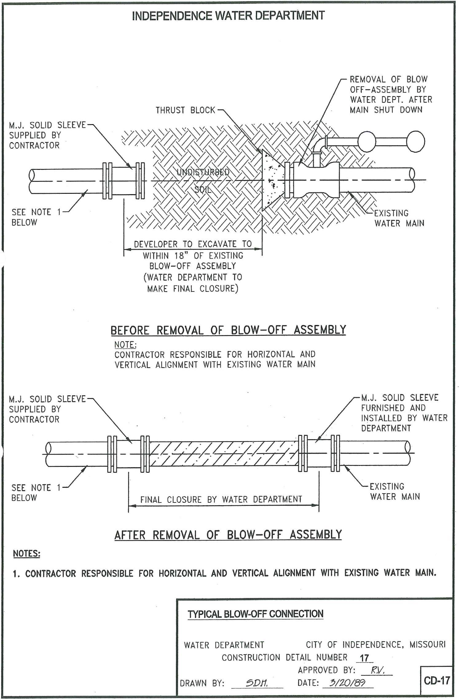
LB-7. CONNECTIONS TO EXISTING MAINS: When the plans call for a tapping sleeve to be installed on an existing main, the Water Department will make connection of new water mains to existing water mains, as shown on Construction Details CD-16 and CD-17 at the expense of the applicant per Contract Agreement Form #2.
On Construction Detail CD-16, “Typical Tapping Sleeve Connection,” it shall be the responsibility of the Contractor to excavate, maintain, barricade and backfill the tap hole.
OnConstructionDetailCD-17,“TypicalBlow-offConnection,”Contractorshallexcavatewithin18feetof the existing blow-off assembly.
In both Detail CD-16 and Detail CD-17, it is the Contractor’s responsibility for horizontal and vertical alignment with existing water main
LB-8. STREETSURFACERESTORATION: Whereverstreetsurfacingiscutordisturbed,theContractor shallremoveandrestoreallstreetorroadwaypavement,furnishingallnecessarylaborandmaterials. Care and caution shall be observed when cutting the existing pavement for the installation of the water mains. The opening shall be made with tools designed for cutting the pavement with a minimum of damage to the surrounding area.
It shall be the responsibility of the Contractor to determine the nature and thickness of all pavements and surfacings to be cut and replaced together with any base courses required in connection therewith.
Concretepavement,asphalticsurfacecourse,macadampavement,andanyothertypeofpavementorsurface coursewhichiscutordamagedshallbereplacedtoconformtothelinesandgradesoftheoriginalpavement and shall beof equal quality,thickness, andappearanceto thatremoved. Materials andworkmanshipshall conform to Street Cut Restoration Standards, prepared by the Public Works Department of Independence, Missouri, Public Works Department of Jackson County, Missouri, or Missouri Highway Transportation Commission.
Temporary surfacing shall be provided as necessary during construction so that all streets are kept in passable condition.
-21-
WATER MAINS NEAR SEWERS
WMS-1. HORIZONTAL SEPARATION: In accordance with the Missouri Department of Natural Resources, water mains shall be laid at least 10 feet, horizontally from any sanitary sewer, drainage pipe, stormsewer,ormanhole. Whenlocalconditionspreventalateralseparationof10feet,awatermainmaybe laidcloserthan10feettoasanitaryorstormsewer,providedthatthewatermainislaidinaseparatetrench, or on an undisturbed earth shelf located on one side of the sewer at such an elevation that the bottom of the water main is at least 18 inches above the top of the sewer. When it is impossible to obtain proper horizontal and vertical separationas stipulated above,thesewermust beconstructedofmechanical or slipon ductile iron pipe and should be pressure-tested to assure water-tightness before backfilling.

WMS-2. VERTICALSEPARATION: Wheneverwatermainsmustcrosssanitarysewers,housesewers,or stormdrains,thewatermainshallbelaidatsuchanelevationthatthebottomofthewatermainis18"above the top of the drain or sewer. A full length of water main pipe shall be centered over the sewer line to be crossed so that the joints will be equally distant from the sewer and as remote therefrom as possible. This verticalseparationshallbemaintainedforthatportionofthewatermainlocatedwithin10feet,horizontally, or any sewer or drain it crosses. See Construction Detail CD-18, “Typical Sanitary Sewer Main Crossing Water Main.”
WMS-3. UNUSUALCONDITIONS: Whereconditionspreventtheminimumverticalseparationsetforth above from being maintained, or when it is necessary for the water main to pass under a sewer or drain, the water main shall be laid with Tyton ductile iron pipe and the water main shall extend on each side of the crossing to a distance from the sewer of at least 10 feet. In making such a crossing, a full length of water main pipemust becenteredoverorunderthesewerto becrossed,so thatthejoints will beequidistantfrom thesewerand as remotetherefromas possible. Thesewerlinemust also beconstructedofductileironpipe with slip-on or mechanical joints until the normal distance from the sewer line to the water main is at least 10 feet. Where a water main must cross under a sewer, a vertical separation of 18 inches between the bottomofthesewerandthetopofthewatermainshallbemaintained,withadequatesupport,especiallyfor thelargersized sewerlines, to prevent them from settlingonandbreaking thewatermain. Thesewer shall be constructed of ductile iron pipe for a distance of 10 feet on either side of the crossing, or other suitable protection as approvedbytheWaterDepartment shall beprovided. Wheretheseconditions cannot bemet, theWaterDepartmentshallbeconsultedastotheprecautionstobetakentoprotectthepublicwatersupply.
WMS-4. SEWERMANHOLES: Nowaterpipeshallpassthrough,orcomeintocontactwith,anypartofa sewer or a sewer manhole.
-22-
WATER MAIN DISINFECTION
WD-1. WATERMAINDISINFECTION: Flushing,disinfection,andsamplingofthenewpipesystemwill be done by the Independence Water Department. The new pipe shall remain isolated from the existing system until satisfactory laboratory results can be obtained.

Pipeduringinstallationmustbekeptfreeofdirt,debrisandcontamination,asprovidedinAWWAStandard C600. Should the pipeline require excessive flushing, disinfection or other cleaning procedure necessary prior to satisfactory lab results, such work will be at the expense of the Developer or Contractor.
DeveloperorContractortoprovideHTHtogivea50ppmsolutionwhenthewatermainisfilledwithwater by the Independence Water Department.
-23-
CONCRETE SPECIFICATIONS
CS-1. SCOPE: These specifications are intended primarily for concrete to be used for thrust blocks. Concreteforallroadwaypavementand/orcurbandgutterreplacementshallconformtotherequirementsof the appropriate authority having jurisdiction thereof.
CS-2. CONCRETE: The concrete shall be MCIB A618-1-4 as designated by the Mid-West Concrete Industry Board, Inc., Kansas City, Missouri.
CS-2.01. Cement: The cement shall be Portland Cement Type I unless high early strength is required in whichinstanceTypeIIIshallbeused. Allcementshallconformtothe“StandardSpecificationforPortland Cement,” ASTM Serial Designation C150.
CS-2.02. Aggregate: All aggregates shall conform to the appropriate bulletins and specifications of the Mid-West Concrete Industry Board, Inc.
CS-2.03. Water: Water for mixing and curing concrete shall be clean and free from injurious amounts of sewage, oil, acid, alkali, salt, or organic matters. (Only potable water will be acceptable without testing.)

CS-3. MIXING: Ready-mixed concrete shall be used unless otherwise prohibited by the Engineering Supervisor or Inspector.
Ready-mixed concrete shall be mixed and delivered in accordance with the requirements set forth in the “Standard Specifications for Ready-Mixed Concrete,” ASTM Serial Designation C94.
CS-4. FORMS: Suitable and substantial forms shall be provided for all thrust blocks. All forms shall be constructedandmaintainedplumbandtrue,securelybracedandshored,andtightenoughtopreventleakage of mortar.
CS-4.01. Forms shall be constructed of sufficient size to permit the entire bearing area of thrust block to bear against undisturbed earth. There shall be no form material between the thrust area and undisturbed earth. See Construction Details CD-6, CD-7 and CD-7A.
CS-5. PLACING OF CONCRETE. Only those methods and arrangements of equipment shall be used which will reduce to a minimum any segregation of coarse aggregate from the concrete.
Concreteshallbedepositedintotheformsoronthegradeasnearlyaspracticableinitsfinalpositionandin such manner that the concrete will completely fill the forms.
-24-
CONCRETE SPECIFICATIONS (Cont.)
Concretethathaspartiallyhardenedorhasbeencontaminatedbyforeignmaterialshallnotbeusedandshall be discarded.
Concreteshallnotbeplacedonorcomeincontactwithfrozensubgradeorformsandequipmentcontaining ice or snow.
Concrete, when placed, shall have a slump not to exceed four (4) inches for thrust blocks.
CS-6. CURING: All regular concrete shall be cured for a period of not less than seven (7) days, and concrete made with high early strength cement shall be cured not less than five (5) days unless otherwise directed or specified by the Inspector.
-25-
