CITY OF INDEPENDENCE, MISSOURI
WATER SERVICE LINE AND BACKFLOW PREVENTION STANDARDS
Last Update: 02/28/18

IF YOU HAVE ANY QUESTIONS, PLEASE CONTACT
Regarding the plans, backflow prevention, specifications and drawings:
Steve Engelke, Engineering GIS Technician – (816) 325-7652
Scott Howell, Engineering, Supervisor. - (816) 325-7650
Chuck Jones, Engineering Tech II – (816) 325-7654
General Index General Description Page No. FORWARD Forward 1 SECTION 1 Timing and Information Required for Tap Application 2 SECTION 2 Intent of Installation Standards and Requirements 3 SECTION 3 Taps - Water Service Line Connection - Excavation Standards and Requirements 4 SECTION 4 Installation Standards and Requirements for Water Service Lines - Depth and Termination Points 5 SECTION 5 Water Service Line Components - Size and Material Requirements 6 & 7 SECTION 6 Water Service Line Components Parts - Master Water Service Line 8 SECTION 7 Installation Standards and Requirements for Water Service Lines - Conflicts with Sewer Lines 9 SECTION 8 Water Service Line Component Parts - Meter Box, Stop Box, Stop Cock, etc. 10 SECTION 9 Installation Standards and Requirements for Water Service Lines - Alignment of Water Services Line Between City’s Main and Premises 11 & 12 SECTION 10 Disconnection of Abandoned Water Service Lines 13 SECTION 11 Notification for Tap 14 SECTION 12 Discontinuance of Service Cross-Connection 15 SECTION 13 Installation Requirements for Backflow Preventer Drawing - Options 16 16-A SECTION 14 Rules of Department of Natural Resources - Division 60 – Public Drinking Water Program; - Chapter 11 – Backflow Prevention 17 - 20
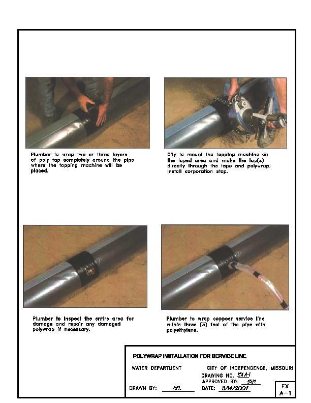
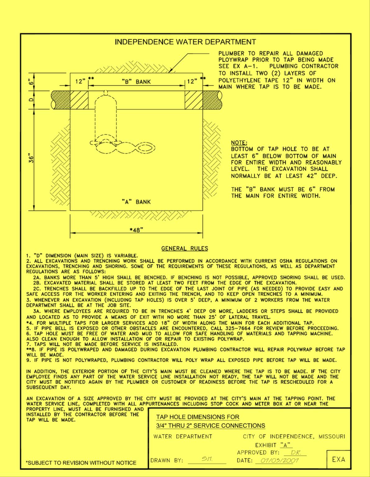
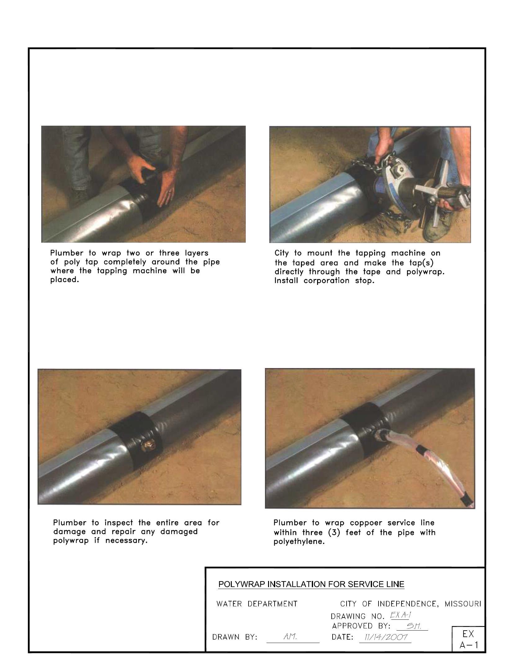
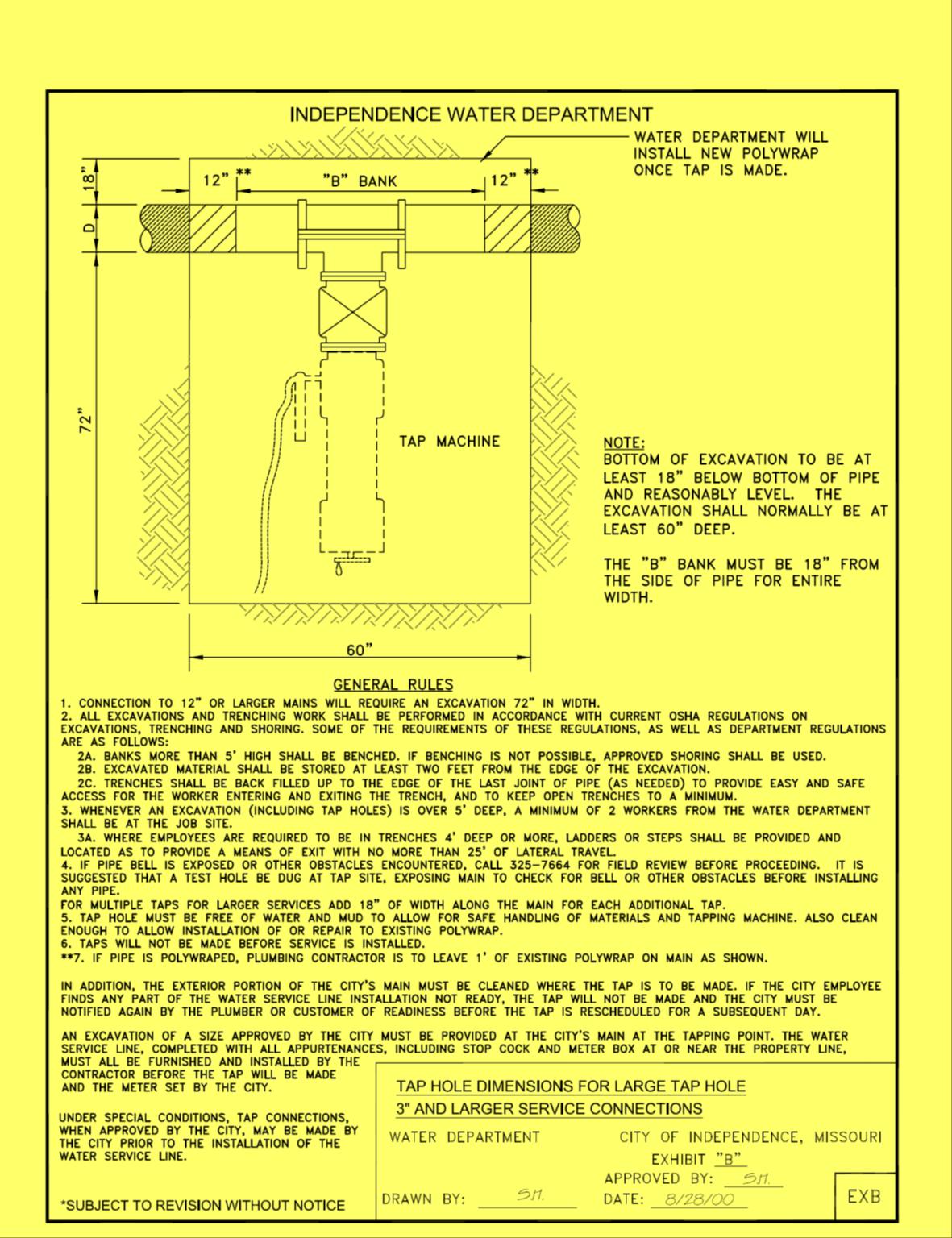
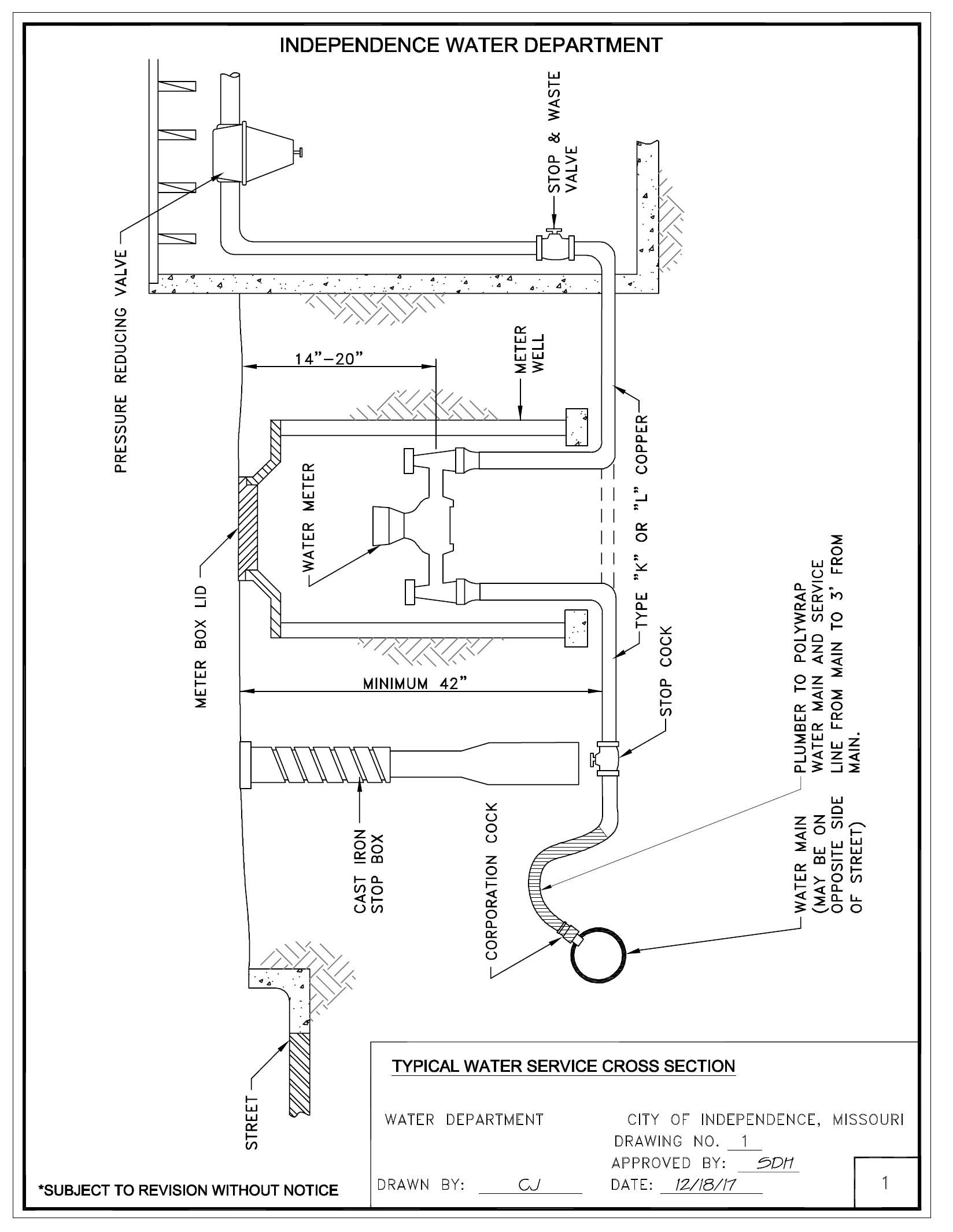
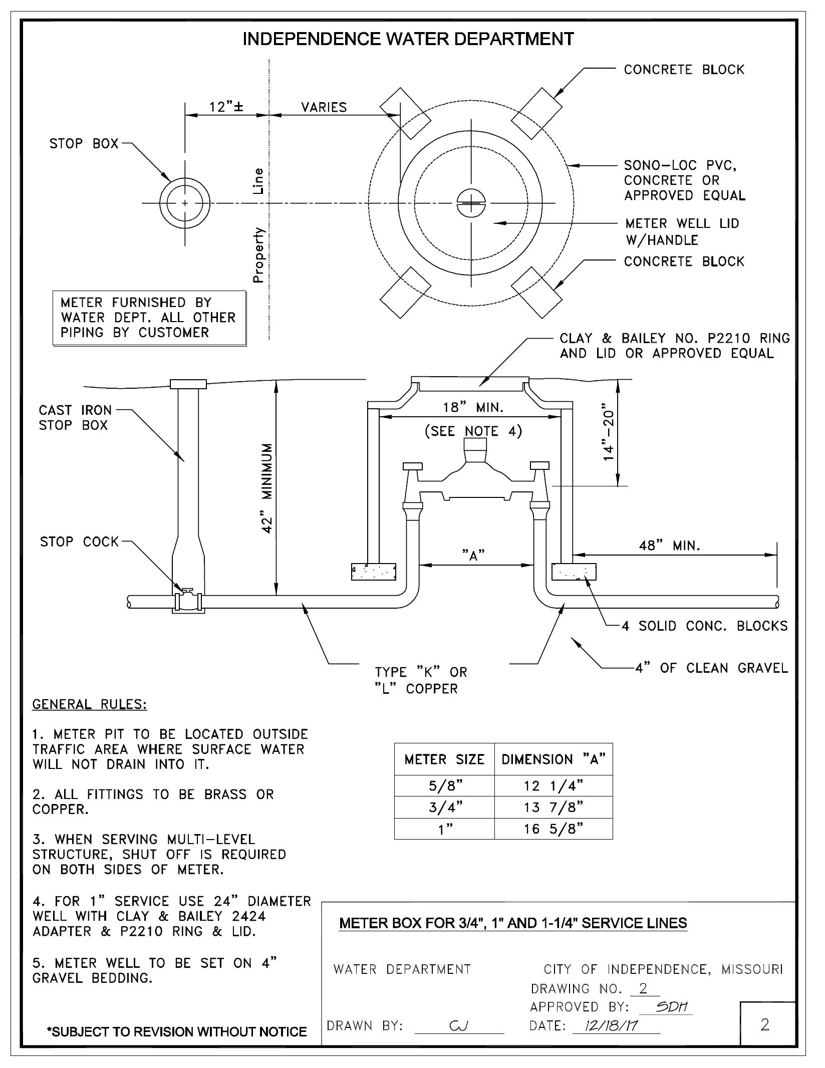
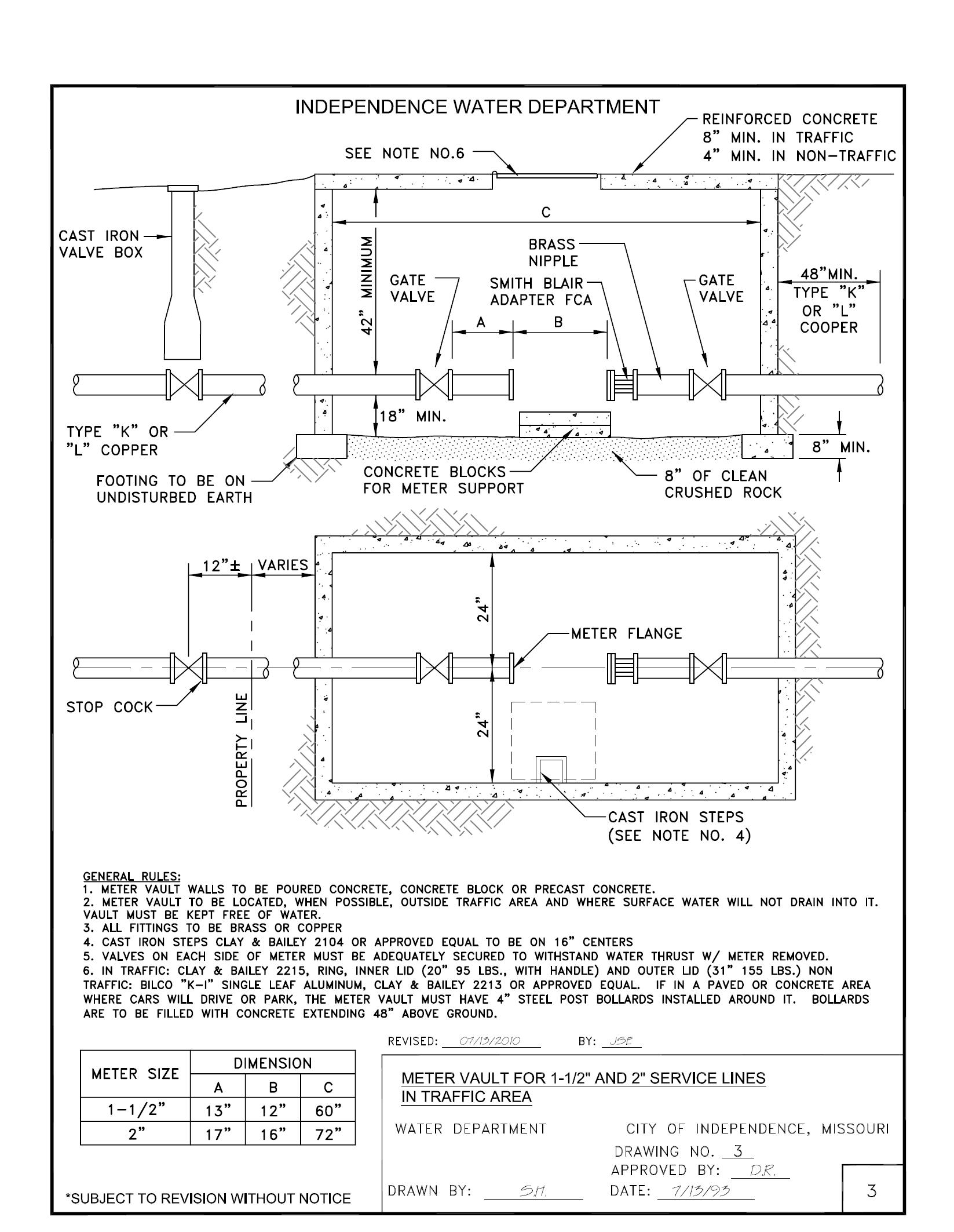
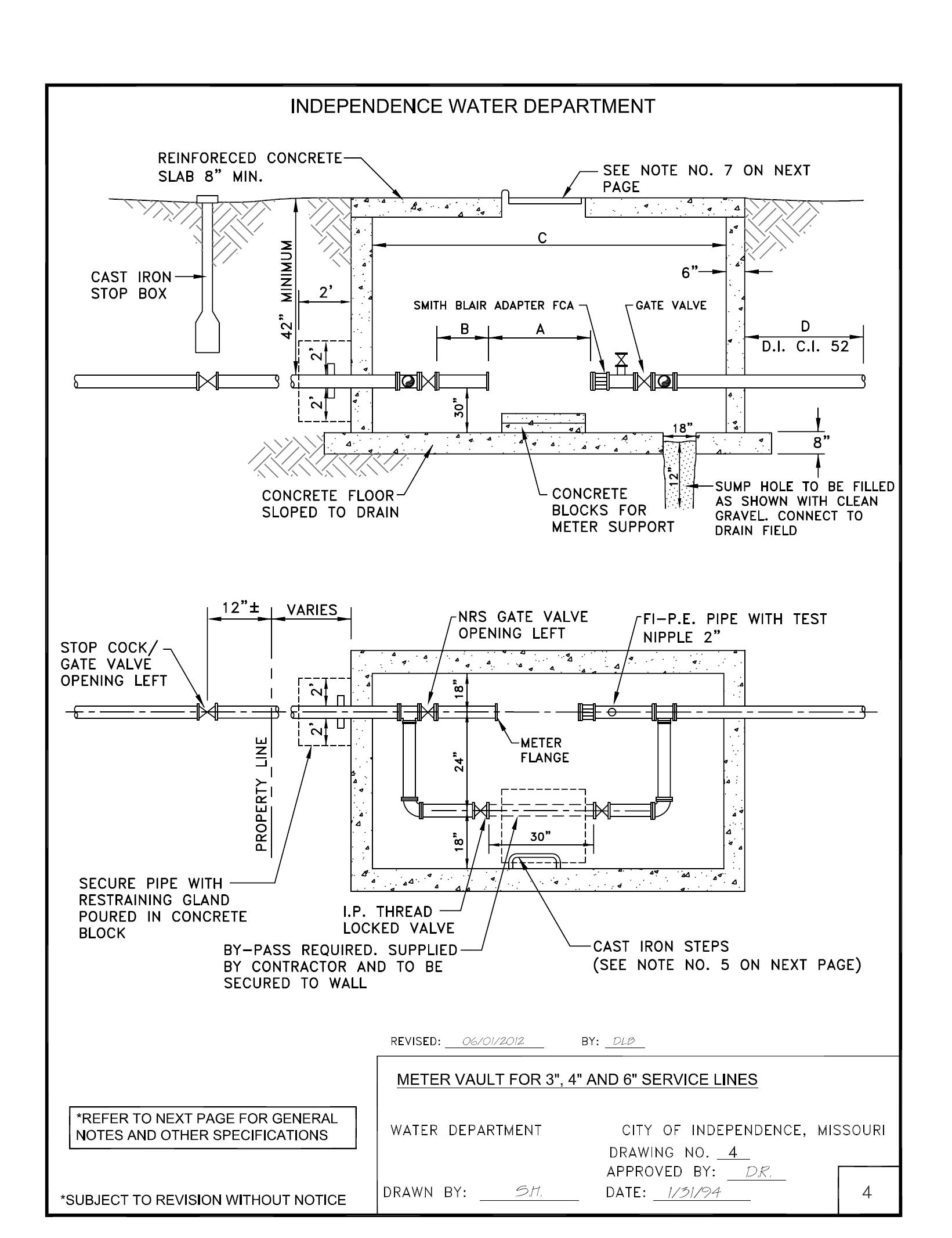
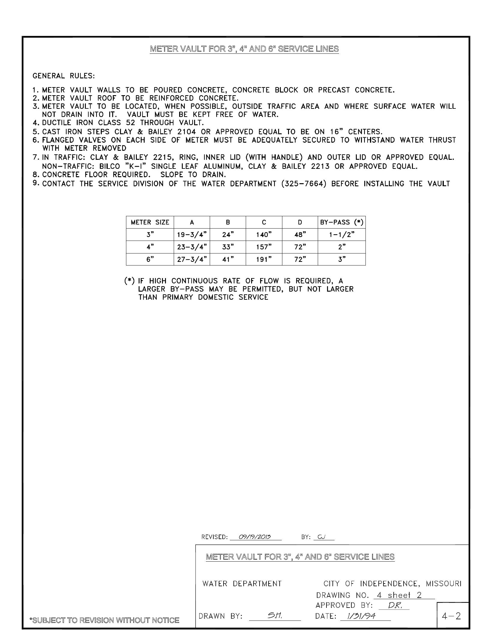
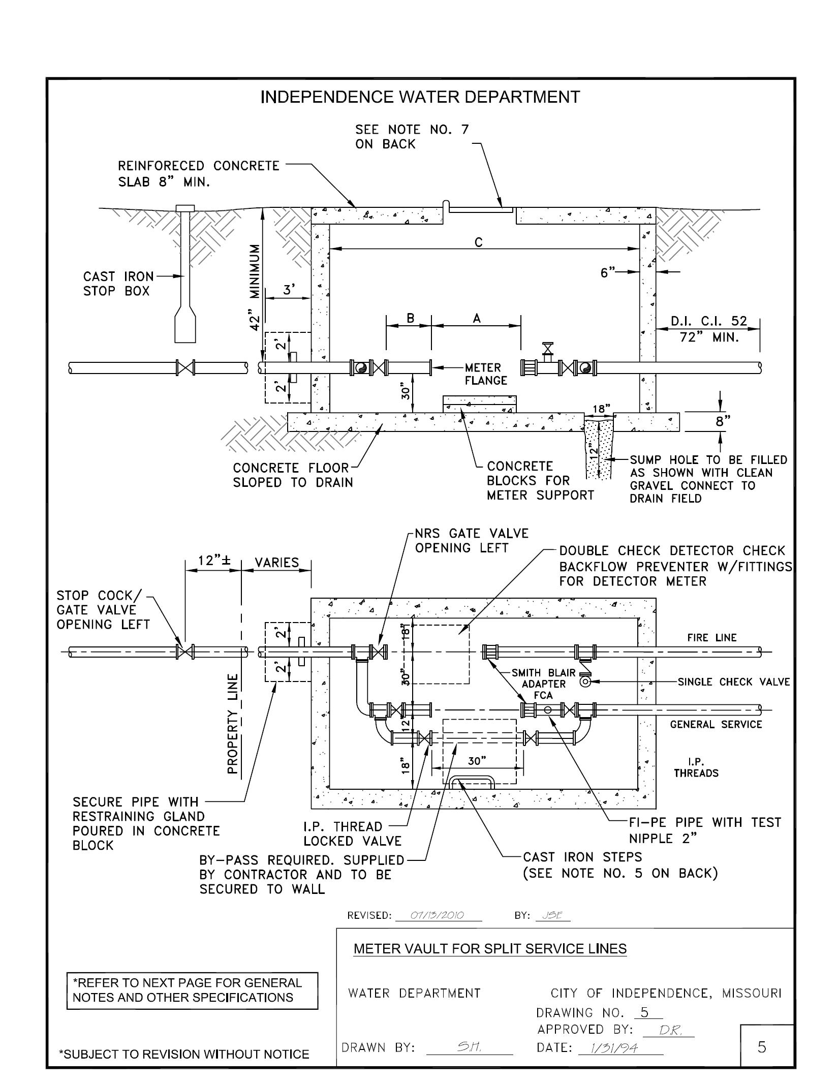
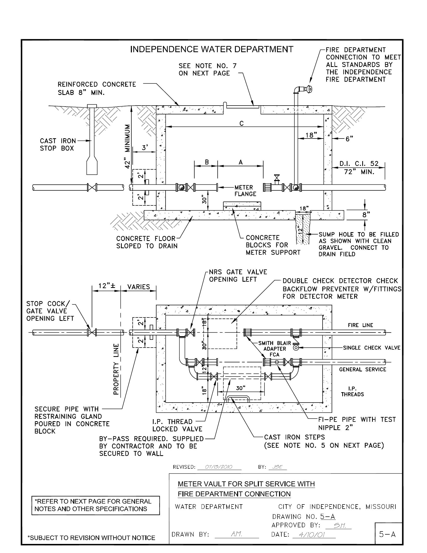
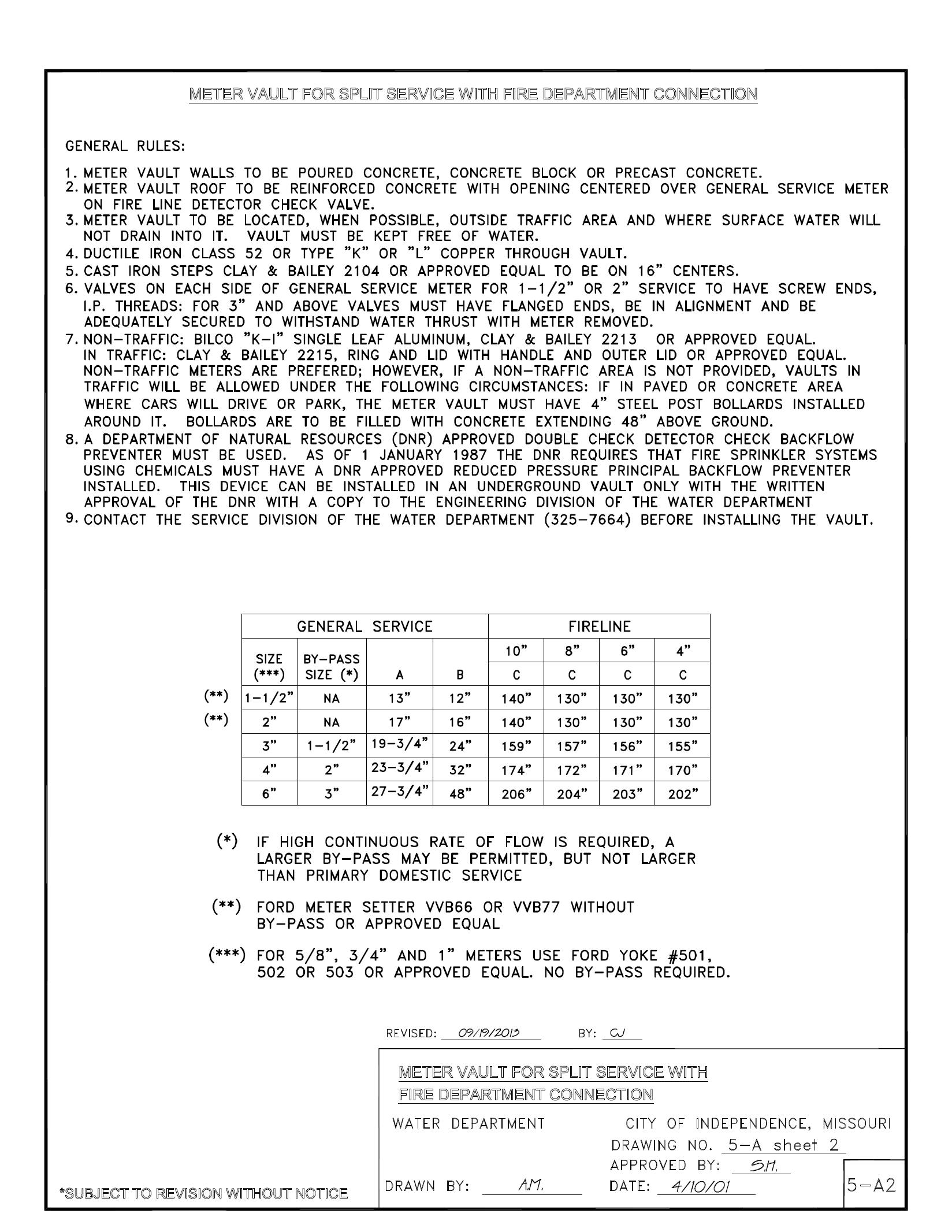
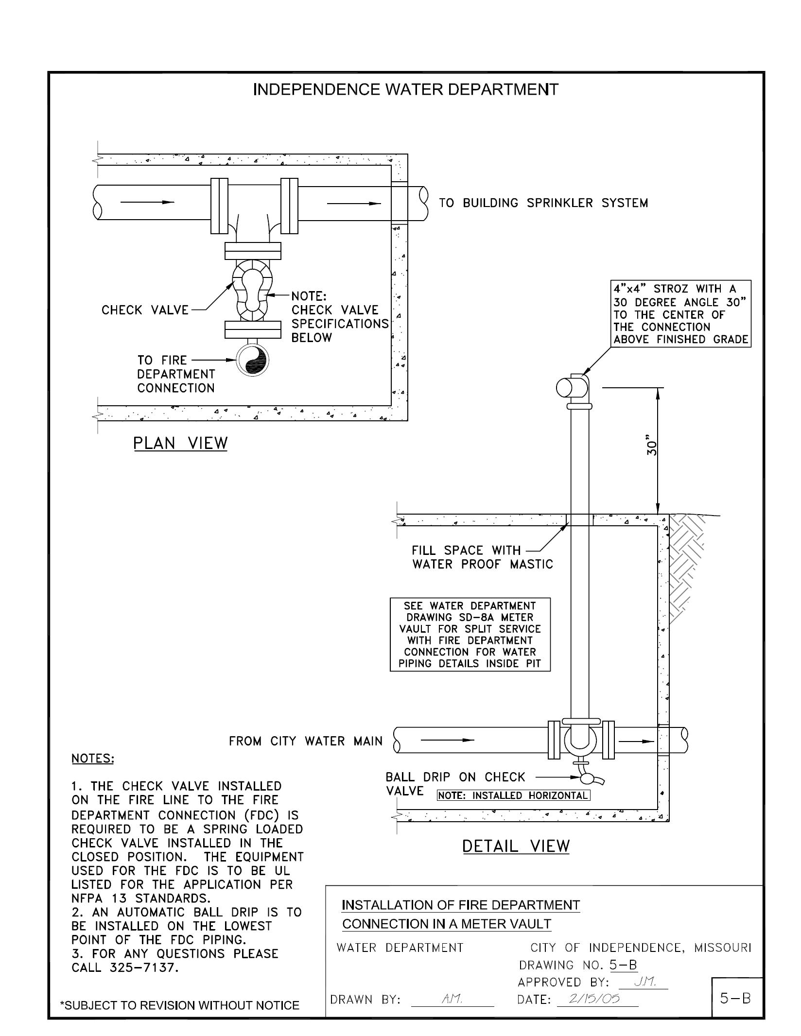
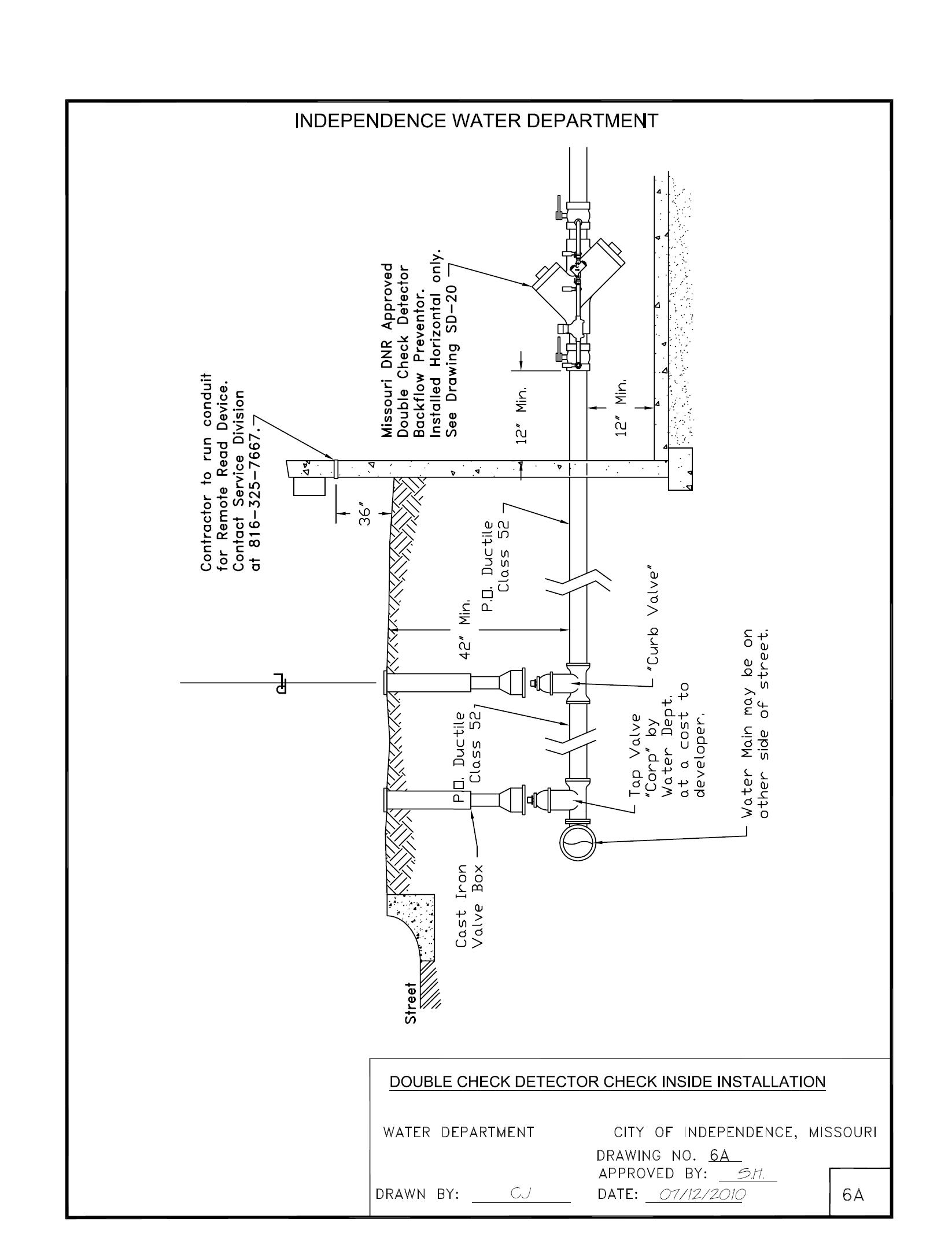
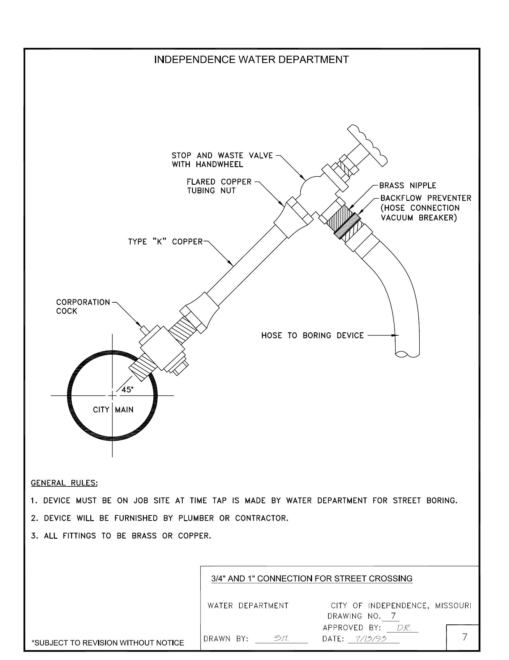
General Index (Cont.) General Description Page No. EXHIBIT “A” Tap Hole Dimensions for ¾” thru 2” Service Connections EXA EXHIBIT “A-1” Polywrap Installation for Service Line EX A-1 EXHIBIT “B” Tap Hole Dimensions for Large Tap Holes 3” and Larger Service Connections EXB DRAWING 1 Typical Water Cross-Section – Domestic Water Service Line 1 DRAWING 2 Meter Box for ¾”, 1” and 1-1/4” Service Lines 2 DRAWING 2A Ford Meter Yoke for ¾”, 1” and 1-1/4” Service Lines 2-A DRAWING 3 Meter Vault for 1-1/2” and 2” Service Lines in Traffic Areas 3 DRAWING 3A Meter Vault for 1-1/2” and 2” Service Lines in Non-Traffic Areas 3-A DRAWING 4 Meter Vault for 3”, 4” and 6” Service Lines 4 & 4-2 DRAWNING 5 & DRAWNING 5-A Meter Vault for Split Service Lines 5 & 5-2 DRAWING 5A & DRAWNING 5A2 Meter Vault for Split Service with Fire Department Connection 5-A & 5-A2 DRAWING 5B Installation of Fire Department Connection in a Meter Vault 5-B DRAWING 6 Meter Vault for Double Check Detector Check 6 DRAWING 6A Double Check Detector Check Inside Installation 6-A DRAWING 7 ¾” and 1” Connection for Street Crossing 7 DRAWING 8 Installation Standards and Requirements for Water Service Line – City Main Parallel to Street 8 DRAWING 9 Installation Standards and Requirements for Master Water Service Line 9 DRAWING 10 Installation Standards and Requirements for Water Service Line – Corner Lot 10 DRAWING 11 Installation Standards and Requirements for Water Service Line - City Main Not Parallel to Street 11
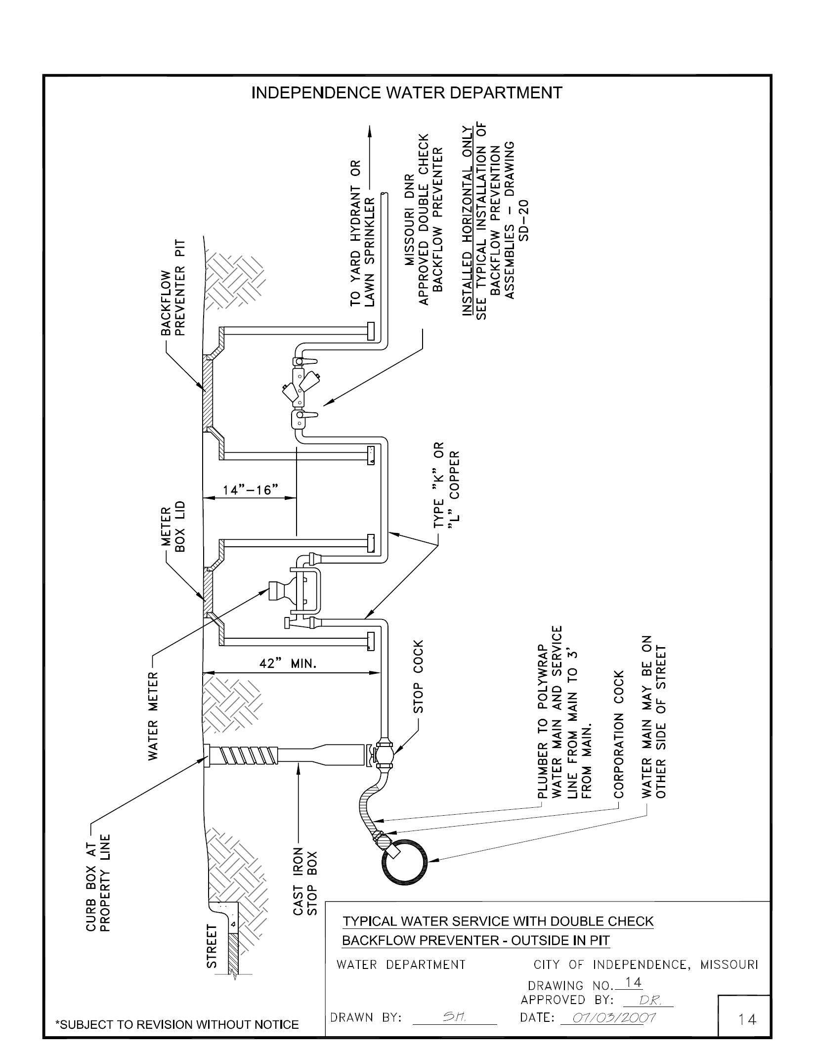
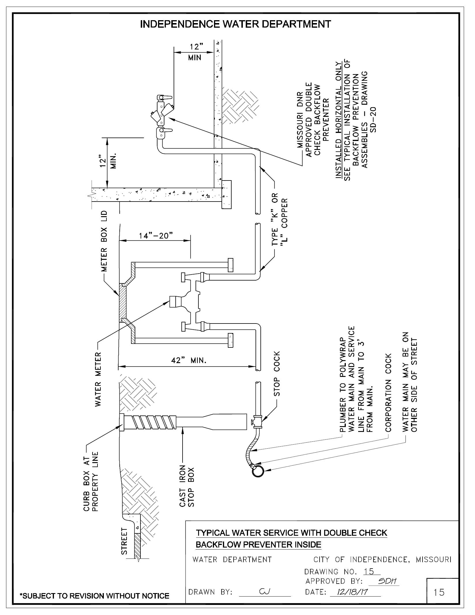
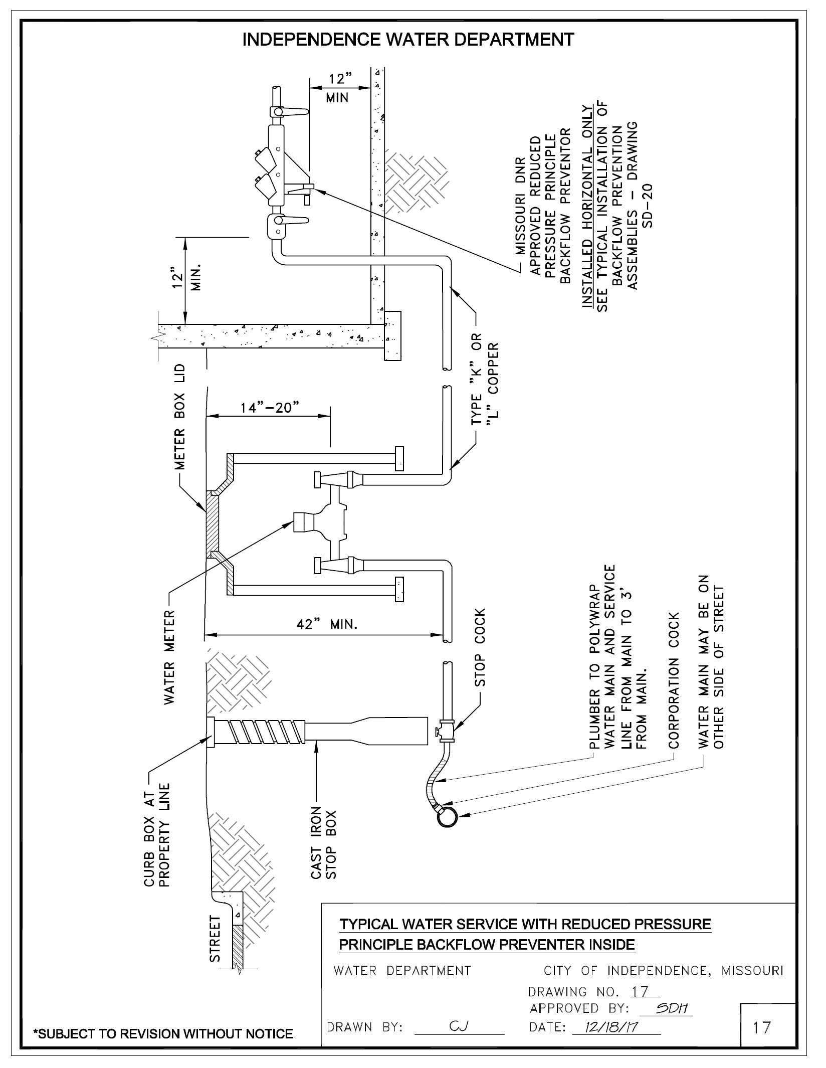
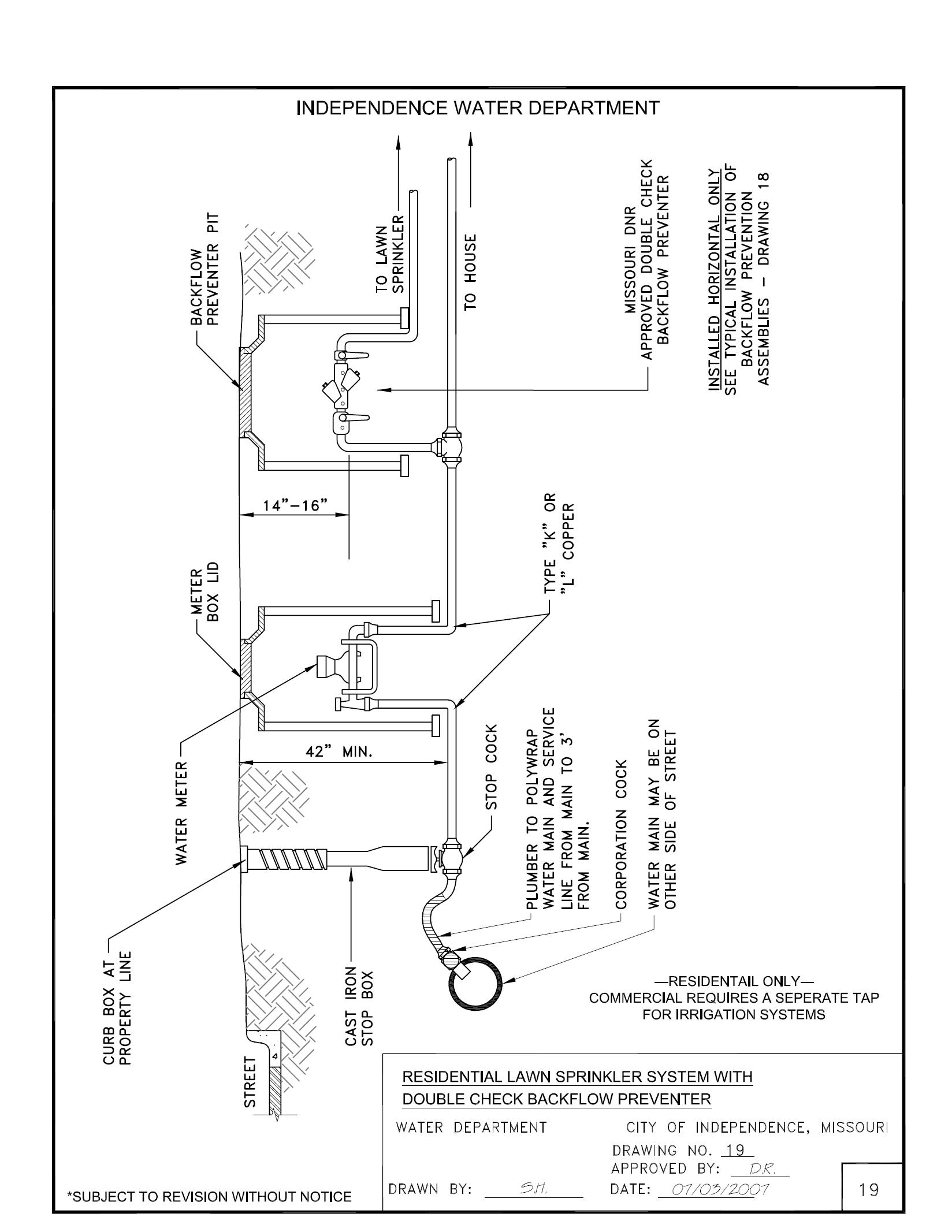
General Index (Cont.) General Description Page No. DRAWING 12 Installation Standards and Requirements for Water Service Line Existing Slab on Grade 12 DRAWING 13 Installation Standards and Requirements for Water Service – Flag or Irregular Shaped Lots 13 DRAWING 13A Curb Valve Replacement Detail –¾" thru 2” Service Connections 13-A DRAWING 13B Meter Vault Riser Detail 13-B DRAWING 13C Meter Well Removal Detail 13-C DRAWING 14 Typical Water Service with Double Check Backflow Preventer Outside in Pit 14 DRAWING 15 Typical water Service with Double Check Backflow Preventer Inside 15 DRAWING 16 Typical Water Service with Reduced Pressure Principle Backflow Preventer Outside 16 DRAWING 17 Typical Water Service with Reduced Pressure Principle Backflow Inside 17 DRAWING 18 Typical Installation of Backflow Prevention Assemblies 18 DRAWING 19 Residential Lawn Sprinkler with Double Check Backflow Preventer 19 DRAWING 20 Missouri DNR Regulation Clause Regarding Backflow Prevention 20
FORWARD
The City of Independence Water Department is dedicated to helping its customers realize optimum value from its water service. Experience has shown that uniform standards for installation are the best way to accomplish our common goals. These standards are not intended to be restrictive or burdensome, but to assist in expediting service connections and backflow installations. It is, therefore, required that customer’s service line installation and backflow comply with these standards.
This booklet is offered to assist architects, engineers, contractors and inspectors in the planning of water service and backflow preventer installations. The City of Independence Water Department is not responsible for the design or installation of customer-owned services and backflow preventers.
No set of rules or instructions will cover all conditions. The Water Department welcomes and encourages all inquiries concerning unusual or special needs of customers.
The Water Department should be contacted about each project as early as possible to provide time for necessary plan review, job checking, scheduling, and proper coordination.
Where new water service installations, backflow installations, additions, or alterations are contemplated, inquiry should be made in advance of design or purchase of equipment. Failure to do so may result in unnecessary costs to the customer for service relocations and possible delay in providing service.
Due to constant progress in the development of materials and methods, some procedures outlined herein may be modified. Upon request, information will be supplied concerning changes and revisions. Persons making regular use of this booklet should maintain contact with the Water Department.
City of Independence Water Department
-1-
City of Independence Water Department
SECTION 1
TIMING AND INFORMATION REQUIRED FOR TAP APPLICATION
Taps are made by the City of Independence Water department and only after the proper application and payments are made by the customer or the customer’s authorized agent (the authorized agent will be required to have a letter from the owner stating that he/she has the owner’s permission to sign up for the water meter and tap) for the tap and service. All applications shall be made at the Water Department office (Engineering Division) at 11610 E. Truman Rd. Request for taps and metered service must be filed in writing at least forty-eight (48) hours in advance of need. As a part of the proper application for a tap, the following data will be required:
1. Subdivision Name
2. Lot Number or description of property and survey
3. Street Name
4. House Number
5. Name of Applicant
6. Name of Property Owner
7. Size of service line to be installed
8. Maximum gpm
9. Permit Application for Opening Street or Right of Way
On water service line connections for any premises other than a single-family residential dwelling or duplex residential dwelling, the application for tap must be preceded or accompanied by four (4) copies of appropriate plans showing proposed premises to be served, service line size, service line, stop cock, meter vault location, and property lines for review by the Water Department’s Engineering and Service Divisions for compliance with its Rules, at least two (2) days prior to the need for tap and service. Such plans, prior to submittal to the City, shall have been reviewed and approved by the appropriate fire district or department as to adequacy of fire protection, or if private fire protection is required.
-2WATERDEARTMENT INDEPE ECDEN P N
City of Independence
Water Department
SECTION 2
INSTALLATION STANDARDS AND REQUIREMENTS FOR WATER SERVICE LINES
(Intent of Installation Standards and Requirements)
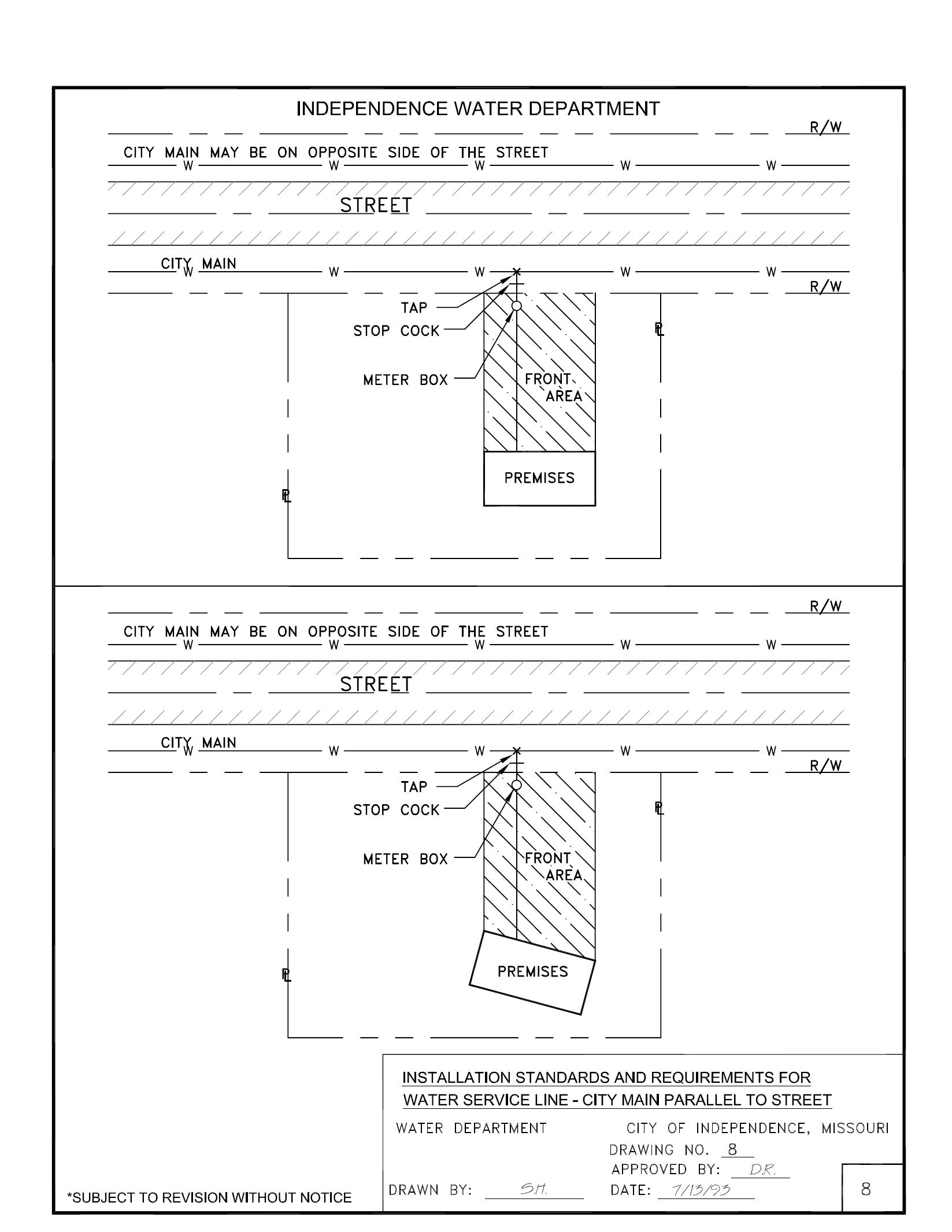
Installation standards and requirements for service lines require a separate water service line for each meter, in a straight line from the tap at the City’s main, through the “stop box” and “meter box” to the premises being served. This arrangement assures a close relationship between the service line and the premises served, and improves the ability to field locate water service line components and read the meter (see Drawing 8).
Water service lines are not owned by the City, thus installation and maintenance responsibility is not that of the City.
All water service line components, such as the tap, stop cock, meter box, and vault, must comply with the provisions of current City specifications and applicable plumbing codes.
A typical cross-sectional view of a domestic water service line supplying a residential or commercial premise is shown on Drawing 1
-3WATERDEARTMENT INDEPE ECDEN P N
City of Independence Water Department

SECTION 3
TAPS
(Water Service Line Connection) (Excavation Standards and Requirements)
The tap excavation at the City’s main must be:
1) Of approved size, construction and shape to allow city personnel to attach and operate the tapping machine, and
2) All excavations and trenching work shall be performed in accordance with current OSHA regulations on Excavations, Trenching, and Shoring. Some of the requirements of these regulations, as well as Department regulations are as follows:
2a) Banks more than five feet high shall be benched. If benching is not possible, approved shoring shall be used.
2b)Excavated material shall be stored at least two feet from the edge of the excavation.
2c) Trenches shall be back-filled up to the edge of the last joint of pipe laid (as needed) to provide easy and safe access for the worker entering and exiting the trench, and to keep open trenches to a minimum.
3) Free of mud and water (See Exhibit “A” and Exhibit “B”)
3a) Whenever an excavation (including tap holes) is over five feet deep, a minimum of two workers form the Water Department shall be at the job site.
3b) Where employees are required to be in trenches four feet deep or more, ladders or steps shall be provided and located as to provide a means of exit, with no more than 25 feet of lateral travel.
In addition, the exterior portion of the City’s main must be cleaned where the tap is to be made.
If the city employee finds any part of the Water Service Line installation not ready, the tap will not be made and the city must be notified again by the plumber or customer of readiness before the tap is rescheduled for a subsequent day. (See Section 11-NOTIFICATION FOR TAP).
An excavation of a size approved by the City must be provided at the City’s main, at the tapping point, and the Water Service Line complete with appurtenances, including stop cock and meter box at or near the property line must all be furnished and installed by the owner or authorized agent before the tap will be made and the meter set by the City. (See Exhibit “A” and Exhibit “B”)
Under special conditions, tap connections, when approved by the City, may be made by the City prior to the installation of the Water Service Line.
-4-
City of Independence Water Department
SECTION 4
INSTALLATION STANDARDS AND REQUIREMENTS FOR WATER SERVICE LINES
(Depth and Termination Points)
Before a tap is made, the following must be satisfied and inspected by the City:
1. All water service lines must be installed at least 3-1/2 feet below the surface of the ground (finished grade) at any point.
2. Water service lines, 3/4" and 1" in diameter, shall be extended to a minimum of one foot (1') beyond the far side of the City’s main.
3. Water service lines with manifolds and multiple flexible leads for multiple connections to the water main shall be extended so that the manifold is not less than six feet (6') and not more than eight feet (8') from the main and each flexible lead extends one foot (1') beyond the far side of the main.
4. Water service lines of ductile cast iron pipe or rigid copper pipe shall be extended approximately eight feet (8') short of the water main. Following the tapping of the City’s main, ductile cast iron or rigid copper water service lines shall be extended and connected by the plumber to the control valve portion of the tap at the City’s main.
-5WATERDEARTMENT INDEPE ECDEN P N
City of Independence Water Department
SECTION 5
WATER SERVICE LINE COMPONENTS (Size and Material Requirements)
For all new or replacement water service lines, the installation must be in accordance with the requirements of all governmental agencies having jurisdiction.
The minimum water service line requirements for material and construction shall be as follows:
A. For New or Replacement Water Service Lines (Minimum 3/4" Inside Diameter) Having an Outside Meter Box.
1. Water Service Lines 3/4" and 1"
a) From the City’s main to the stop cock shall be flexible Type “K” copper.
b) From the stop cock to four feet (4') beyond the meter box shall be flexible Type “K” or “L” copper. Also, copper must be used outside the building wall of the premises served, a minimum of ten feet (10').
2. Water Service Lines Greater Than 1”, But Less Than 4”
a) From the City’s main to the stop cock shall be flexible or rigid Type “K” copper.
b) From the stop cock to four feet (4’) beyond the meter box shall be flexible or rigid type “K” or “L” copper. Also, copper must be used outside the building wall of the premises served, a minimum of ten feet (10’).
3. Water Service Lines 4” and Greater
a) From the City’s main to six feet (6’) beyond the meter box must be a minimum of Class 52 ductile iron pipe conforming to applicable AWWA standards.
4. On copper Water Service Lines, joints (excluding joints on pre-purchased “meter setters”) shall be either flared, compression, or silver soldered. Use of any other type of joint is prohibited, unless specifically authorized in writing by the City.
-6WATERDEARTMENT INDEPE ECDEN P N
B. For replacement water service lines with acceptable inside meter settings, materials shall be the same as for new water service lines, except the copper or ductile iron pipe shall extend from the City’s main to the meter inside the premises served.
C. For water service lines having no meter box (Private Fire Protection Service Lines), materials shall be the same as described in A.2.a), A.2.b), and A.3. above, except that the copper or ductile iron pipe must extend from the City’s main to the premises served. If a detector check valve assembly is provided in the vault as part of the private fire protection service line, then:
1. For private fire protection service lines 4” or greater, AWWA C900 plastic pipe can be used in lieu of ductile iron pipe from six feet (6’) beyond the vault to the premises, or
2. For private protection service lines less than 4”, material other than copper can be used from six feet (6’) beyond the vault to the premises, provided such material is in compliance with local plumbing codes.
SECTION 5 - WATER SERVICE LINE COMPONENTS (Cont.)
-7-
City of Independence Water Department
SECTION 6
WATER SERVICE LINE COMPONENT PARTS (Master Water Service Line)
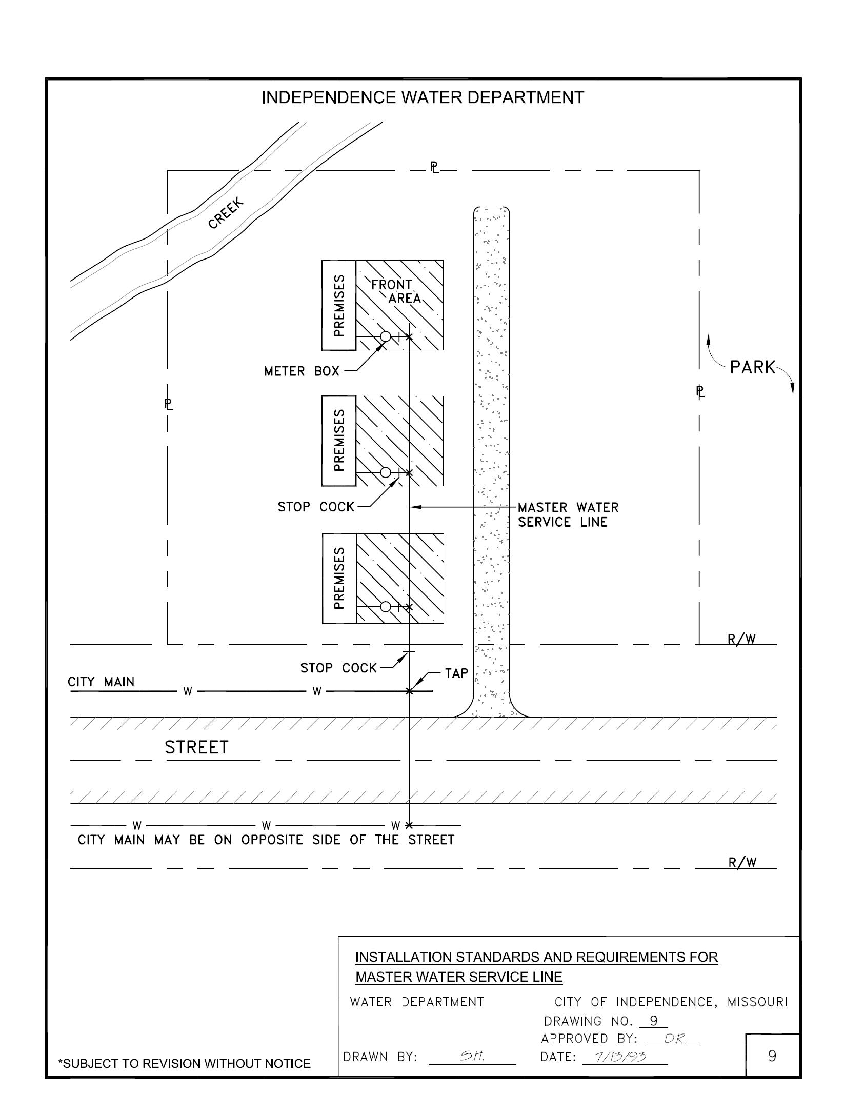
Where installation of a privately owned “Master Water Service Line” is permitted by the City’s Rules, the component or material requirements for the “Master Water Service Line” from the connection of the City’s main throughout its entire length are as follows:
1. For a size 3/4” or 1” – flexible type “K” copper is required.
2. For sized greater than 1”, but less than 4” – flexible or rigid type “K” or “L” copper is required.
3. Sizes 4” and greater – a minimum of Class 52 Ductile Iron pipe is required, conforming to applicable AWWA Standards.
4. In addition to the control valve portion of the tap at the City’s main, a stop cock is required at or near the property line where the “Master Water Service Line” enters the parcel or property (see Drawing 9).
-8WATERDEARTMENT INDEPE ECDEN P N
City of Independence Water Department
SECTION 7
INSTALLATION STANDARDS AND REQUIREMENTS FOR WATER SERVICE LINES
(Conflicts with Sewer Lines)
Water service lines shall be laid in a trench separate from sewer or building drainage trenches. The water service line and sewer trenches are to be horizontally separated by at least ten feet (10'). Where construction of separate trenches is not feasible, and approval is obtained from the appropriate governmental authority, the minimum requirement shall be to install the water service line on an undisturbed earth shelf on one side of the sewer or building drainage trench at such an elevation that the bottom of the water service line is at least eighteen (18) inches above the top of the sewer.
Where the water service line crosses a sanitary sewer main, a minimum of eighteen (18) inches vertical clearance must be provided either above or below the sewer, unless approved in writing by the appropriate governing authority.
The water service line trench from the City’s main to the premises shall not be backfilled until after the tap is made, water turned on and, at the City’s option, the City has made an inspection to ensure compliance with its Rules.
-9WATERDEARTMENT INDEPE ECDEN P N
City of Independence Water Department
SECTION 8
WATER SERVICE LINE COMPONENT PARTS (Meter Box, Stop Box, Stop Cock, etc.)
When a meter (up through 1" in size) is to be installed outside of the building in a meter box, a tee head “angle valve” of bronze material and a design acceptable to the City shall be installed on the inlet side of an integral part of each yoke setting. For meters greater than 1", a water shutoff gate valve shall be installed in the meter box before and after the meter. In addition, on all service line installations, a “stop cock” of a material and design acceptable to the City (2" and smaller must be bronze material; larger than 2" must be gray or ductile cast iron material) complete with stop box shall be installed in the water service line located accessibly on the property line or in public right-of-way (subject to plumbing code requirements) near the right-of-way line.
If a basement meter setting exists, then a “stop cock” of material and design acceptable to the City, complete with stop box, shall be installed in the service line, located accessibly on the property line or in public right-of-way (subject to plumbing code requirements) near the right-of-way line.
A cast iron extension-type stop box of a design acceptable to the City shall be placed over each stop cock so that the stop cock is readily accessible for turning off or on by employees of the City.
The stop cock, of a design acceptable to the City, must be installed in a separate stop box and located in accordance with the applicable plumbing code but in no event shall the location be more than three feet (3') from the property or easement line, unless otherwise approved by the City.
The control valve portion of a tap at the City’s main, which is also required, is not a substitute for the stop cock.
In every water service line installation, a stop and waste valve of a design acceptable to the City shall be installed in the water service line at or immediately beyond the point where the water service line enters the building wall of a premises, and also at a point such that water can be drained out of the pipes in the building. The stop and waste valve must be kept accessible at all times for readily turning water off or on by the occupant of the building or by City’s employees.
-10WATERDEARTMENT INDEPE ECDEN P N
City of Independence Water Department
SECTION 9
INSTALLATION STANDARDS AND REQUIREMENTS FOR WATER SERVICE LINES
(Alignment of Water Service Line Between City’s Main and Premises)
The installation arrangements for all water service lines shall be as follows:
CONDITION “A”
City’s main or master water service line is parallel (or nearly parallel) to the edge of the street and the face of the premises or City’s main is located in an easement where no street exists.
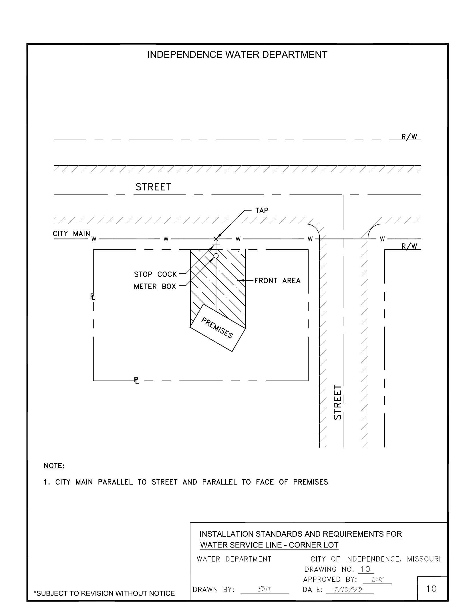
1. The “tap”, “stop cock and stop box” and “meter box” should be in a straight line perpendicular to the City’s main or master water service line and in front of the premises served (see Drawings 8, 9 and 10).
2. The water service line from the “tap” to the premises should be in a straight line perpendicular to the City’s main or master water service line and the face of the premises served.
CONDITION “B”
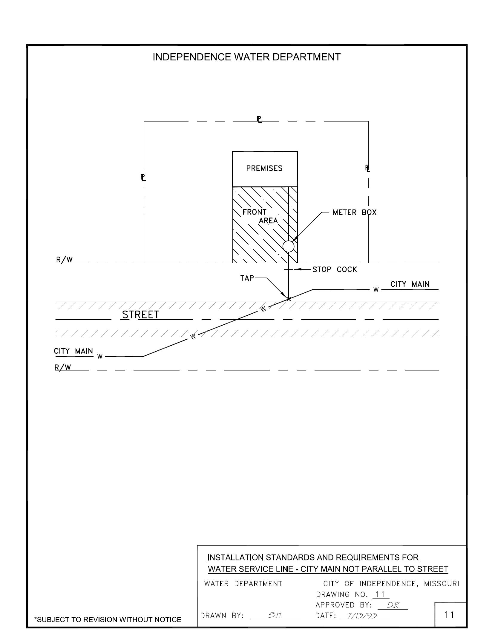
City’s main not parallel to edge of street nor the face of the premises.
1. The “tap”, “stop cock” and “meter box” should be in a straight line perpendicular to the edge of the street and in front of the premises served (see Drawing 11).
2. The water service line portion from the “meter box” to the premises should be in a straight line and, where possible, perpendicular to the premises or, as an alternate, be parallel to the side of the front area of the premises served.
-11WATERDEARTMENT INDEPE ECDEN P N
SECTION 9 - INSTALLATION STANDARDS AND REQUIREMENTS FOR WATER SERVICE LINES (Cont.)
CONDITION “C”
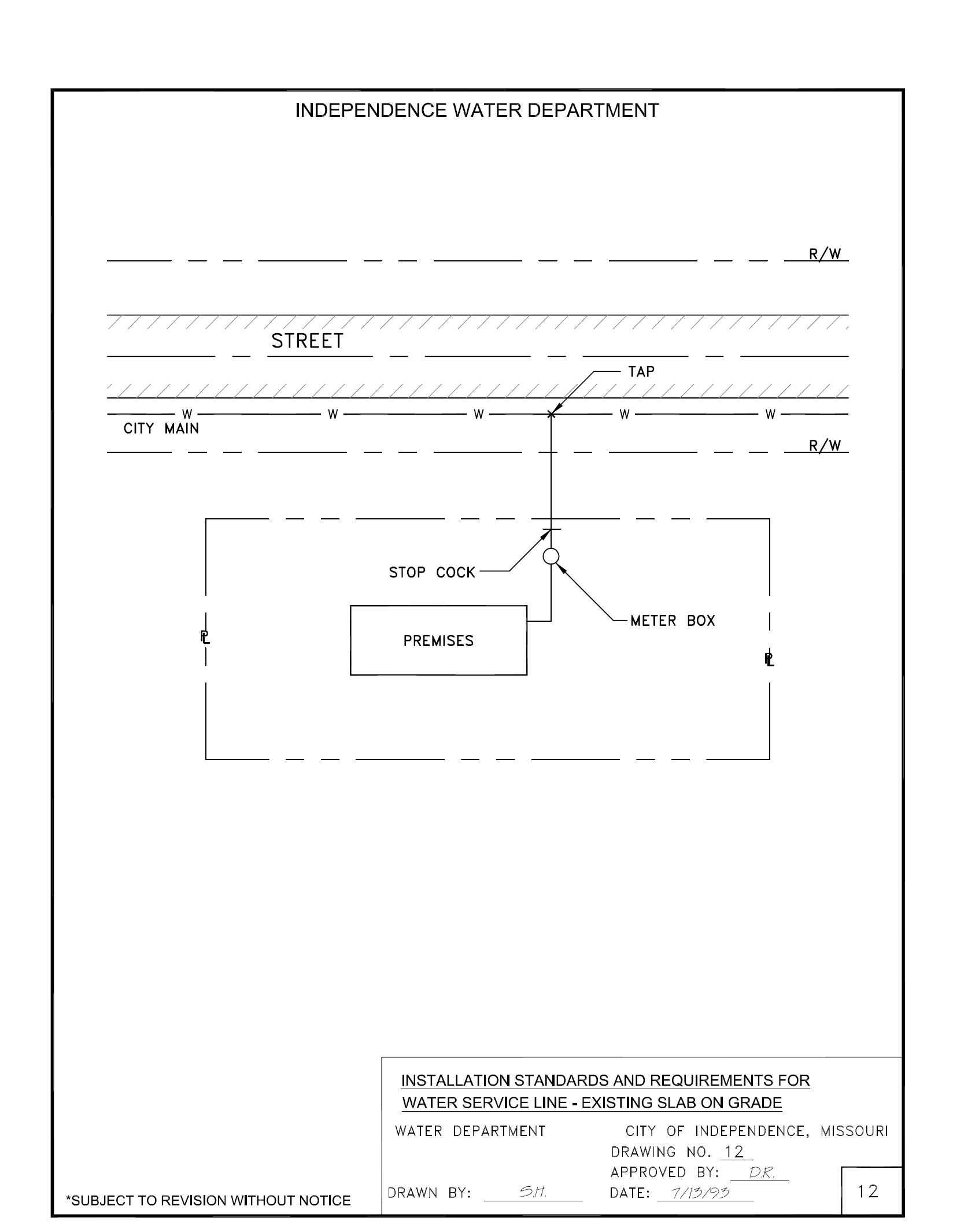
For an existing building constructed on a concrete slab foundation, the water service line may be installed at right angles to the City’s main and then be allowed to pass the building in a line parallel to the side of the building, inside the property line and as close to the building as practicable, and then turn at right angle to enter the building through the side (see Drawing 12). In case such procedure does not allow the water service line to be installed as specified herein, special instructions or variance must be obtained by the plumber or their authorized representative from the Engineering or Service Division of the Water Department.
CONDITION “D”
Service to flag or irregular shaped lots shall be allowed if, in the opinion of the City, such service would not circumvent the location of a proper water main extension under Rule 22.
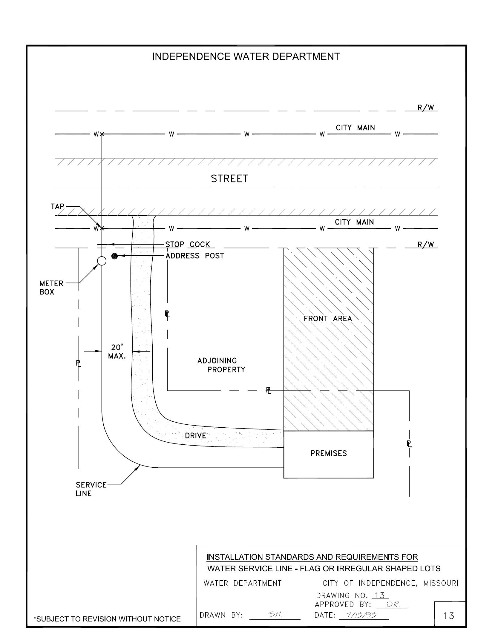
The water service line to a flag or irregular shaped lot must comply with the following (see Drawing 13):
1. The premises to be served must be addressed on the same street or road from which service is to be taken.
2. The driveway entrance of the premises to be served must be on land owned in fee by the owner.
3. The driveway entrance of the premises to be served must have frontage adjacent to the water main.
4. The meter pit and service line to the premises being served must be installed within twenty (20) feet of the center line of the driveway entrance.
5. Identifying objects such as mail boxes or a sign displaying names or addresses must be permanently displayed adjacent to the driveway entrance.
-12-
City of Independence Water Department SECTION
10
DISCONNECTION OF ABANDONED WATER SERVICE LINES
Abandoned or unused Water Service Lines must be disconnected from the “tap” at the City’s main, and the tap(s) must be destroyed. For a corporation cock(s), destruction shall be by capping off the outlet threads with a galvanized cap on the threads of the corp (where) the service line connects City’s water main) or by sawing off the outlet threads. Abandoned taps, other than brass corporation cocks, shall be destroyed as directed by the City.
This disconnection and tap destruction shall be accomplished by the owner of the premises or the owner’s authorized agent as directed by the City. At the option of the City the destruction of the tap may be done by others. A new connection will not be made to service the same premises or a new premises on the same parcel of property or another premises on another parcel of property until all of the abandoned or unused Water Service Lines to the premises, referred to in the paragraph above are disconnected, the tap(s) destroyed, and is inspected by the City of Independence Water Department.
-13WATERDEARTMENT INDEPE ECDEN P N
City of Independence Water Department
SECTION 11
NOTIFICATION FOR TAP
The Water Department Service Division must be notified when the plumber is ready for the tap to be made. This notification is assurance to the Water Department that the plumber has substantially complied with all the current rules and specifications for installing a service line. Completion of the tap does not constitute final approval of the service installation.
The tap will normally be made by the Water Department Service Division forty-eight (48) hours after notification, or sooner if possible.
If the tapper finds the tap hole or service line is not in compliance with current rules and specifications, it is the plumber’s responsibility to complete the necessary work and to re-advise the Water Department of readiness. Upon being re-advised of readiness, the Water Department will reschedule the tap request.
If the Water Department receives a second notice that a specific tap is ready and, upon getting to the site to make the tap, finds that it is not ready, a fifteen dollar ($15.00) fee will be charged to the plumber or customer for that trip and for every subsequent rescheduled trip. Such charges must be paid before the tap is made.
All taps 4” and larger will be inspected prior to the scheduling of the tap being made.
-14WATERDEARTMENT INDEPE ECDEN P N
City of Independence Water Department
SECTION 12
DISCONTINUANCE OF SERVICE CROSS-CONNECTION
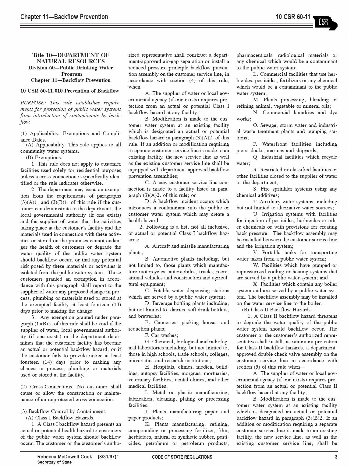
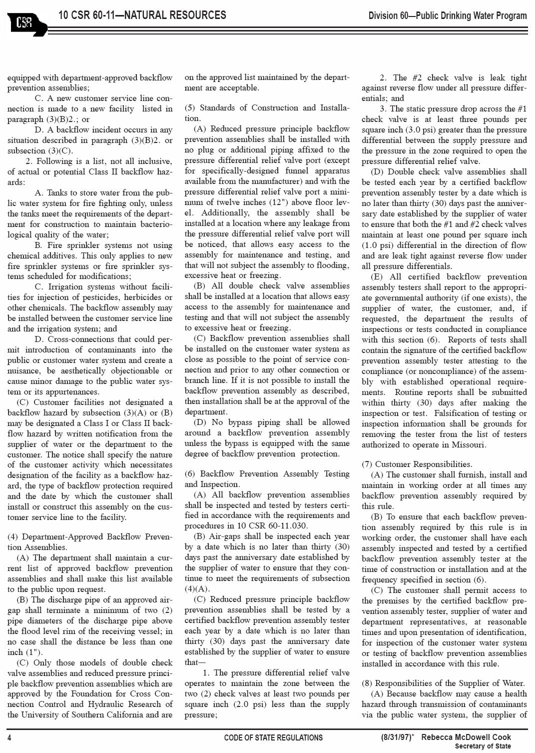
No physical connection will be allowed between either a water service line from a main of the City or the internal plumbing of a premises and any pipe, tank, well, cistern, or other appurtenance which contains polluted or otherwise questionable substances or to a water supply not approved by the Missouri Department of Natural Resources. It shall be unlawful for any person to install or maintain any potable water supply piping which fails to comply with Sections 1001, 1002, or 1003 of the Uniform Plumbing Code, or the standards set out in Title 10, Division 60, Chapter 11 of the Missouri Code of State Regulations (10 SCR 60-11.010, et seq.). Whenever there is a conflict between the Uniform Plumbing Code and 10 CSR 60-11.010, et seq. piping, the more stringent requirement shall apply.
-15WATERDEARTMENT INDEPE ECDEN P N
City of Independence Water Department
SECTION 13
INSTALLATION REQUIREMENTS FOR BACKFLOW PREVENTER
The following items are the installation requirements for a backflow preventer:
A. General Information
All backflow preventers will be installed with the following points in mind:
1. No bypass piping will be approved or allowed without the same degree of backflow protection installed on bypass (see Drawing 18).
2. All backflow preventers will be installed before any tees or wyes, in a horizontal and upright position. The only exception to this requirement is on a lawn sprinkler system (see Drawing 19).
3. All backflow preventers will be tested within thirty (30) days of the initial tap, or of installation date, by a State certified tester.
4. Backflow preventers will be installed at a location that allows easy access to the assembly maintenance and testing and that will not subject the assembly to excessive heat and freezing.
B. Reduced Pressure Principle Assemblies
1. Cannot be installed inside a vault that is below grade.
2. Must be installed with a minimum of 12” between the pressure differential relief valve port and the floor (see Drawings 16 and 17).
3. Will have no plugs or additional piping affixed to the pressure differential relief valve port (except for specifically-designed funnel apparatus available from the manufacturer).
C. Double Check Valve Assemblies
1. Will be allowed to be installed in a pit or inside the building (see Drawings No. 6-A, 14, 15 and 19) See page 16-A. -16-
WATERDEARTMENT INDEPE ECDEN P N

City of Independence Water Department
SECTION 14
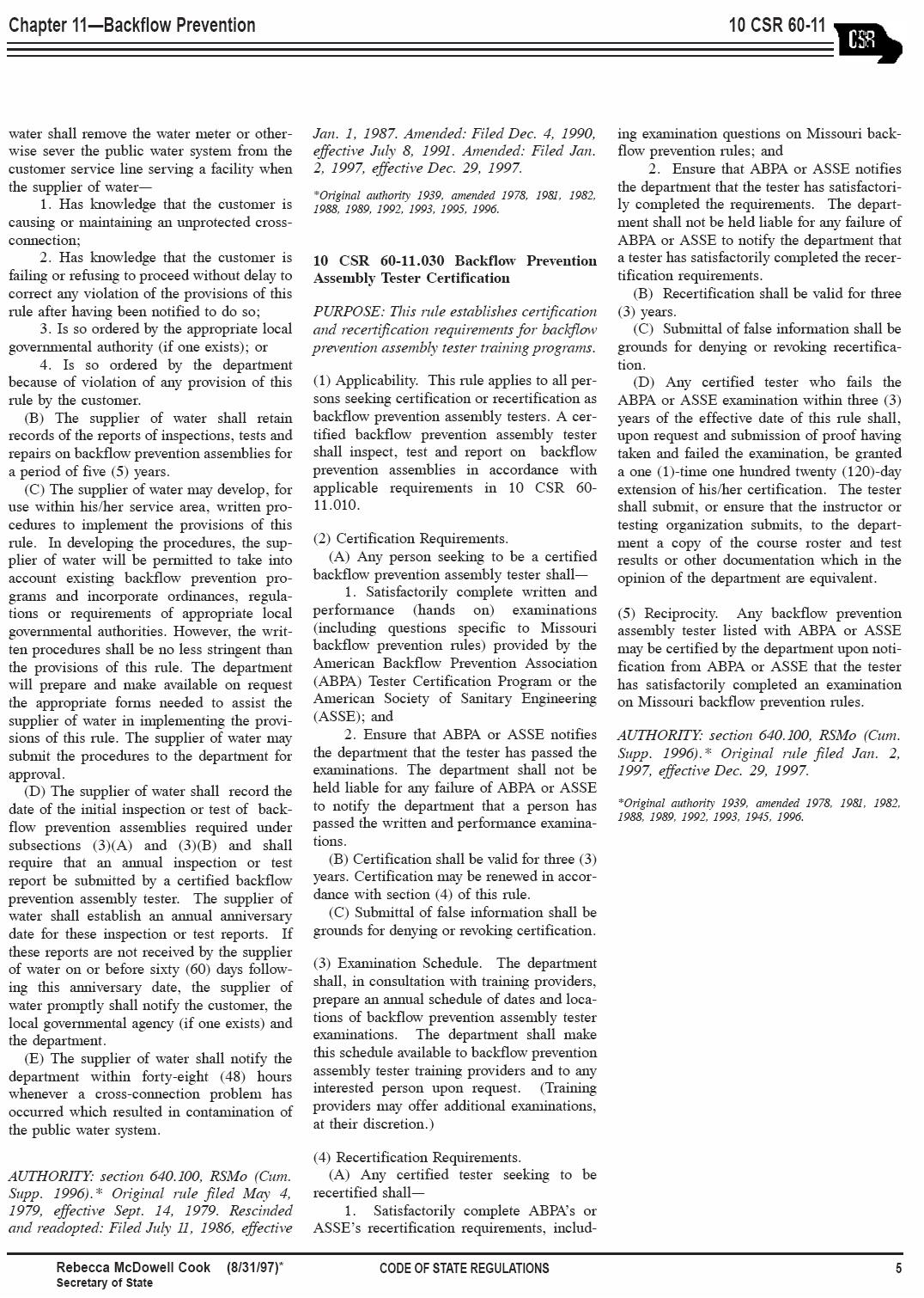
RULES OF DEPARTMENT OF NATURAL RESOURCES
(Division 60 – Public Drinking Water Program; Chapter 11 – Backflow Prevention)
(see attached pages)
-17WATERDEARTMENT INDEPE ECDEN P N
-18-
-19-
-20-
