

PROTOTYPES FORRESILIENT COASTAL SETTLEMENTS: U.S. COAST GUARD_BASE CHARLESTON SPRING 2022: GRADUATE COMPREHENSIVE STUDIO I CLEMSON UNIVERSITY SCHOOL OF ARCHITECTURE PART 04
This book contains the work of the 2022 Graduate Comprehensive Studio at Clemson University. This project involved a close collaboration with the United States Coast Guard and its Base Charleston. This was the third in a series of design studies conducted at Clemson University, in which students and their faculty explored the use of highly-sustainable, advanced timber systems for Department of Defense and Department of Homeland Security buildings. This work was conducted in conjunction with Clemson’s multidisciplinary Wood Utilization + Design (WU+D) Institute, and it was funded by the U.S. Endowment for Forests and Communities. Concurrent studios, looking at other DOD / DHS sites, were conducted at the Universities of Arkansas and Oregon. Together, we thank the U.S. Endowment for Forests and Communities for its generous support.
INTRODUCTION i
As the United States Coast Guard undertakes the largest construction program in our Service’s history, the Clemson University School of Architecture students brought a unique blend of creativity, advances in technology, and out of the box thinking to this project. Their presentations combined conventional concepts of space planning and resiliency with innovative ones like sustainability and carbon emission avoidance. This approach has made us think differently about the way we construct future shore facilities in Charleston and around the globe.”
- Captain John Berry, Commanding Officer USCG Facilities Design and Construction Center
Thank you to the staff and students at Clemson University’s School of Architecture for the remarkable partnership while designing facilities and infrastructure in support of the United States Coast Guard Base Charleston build-out. The proposed site presents unique challenges related to environmental impact, project phasing, coastal resiliency, and user experience. All of the final presentations exceeded expectations, incorporating creative design features and cutting edge practices that would ensure mission support and operational success at an installation positioned to become the premier Coast Guard center of gravity on the east coast.
INTRODUCTION iii
- Lieutenant John Houk, USCG Base Charleston Facilities Engineer
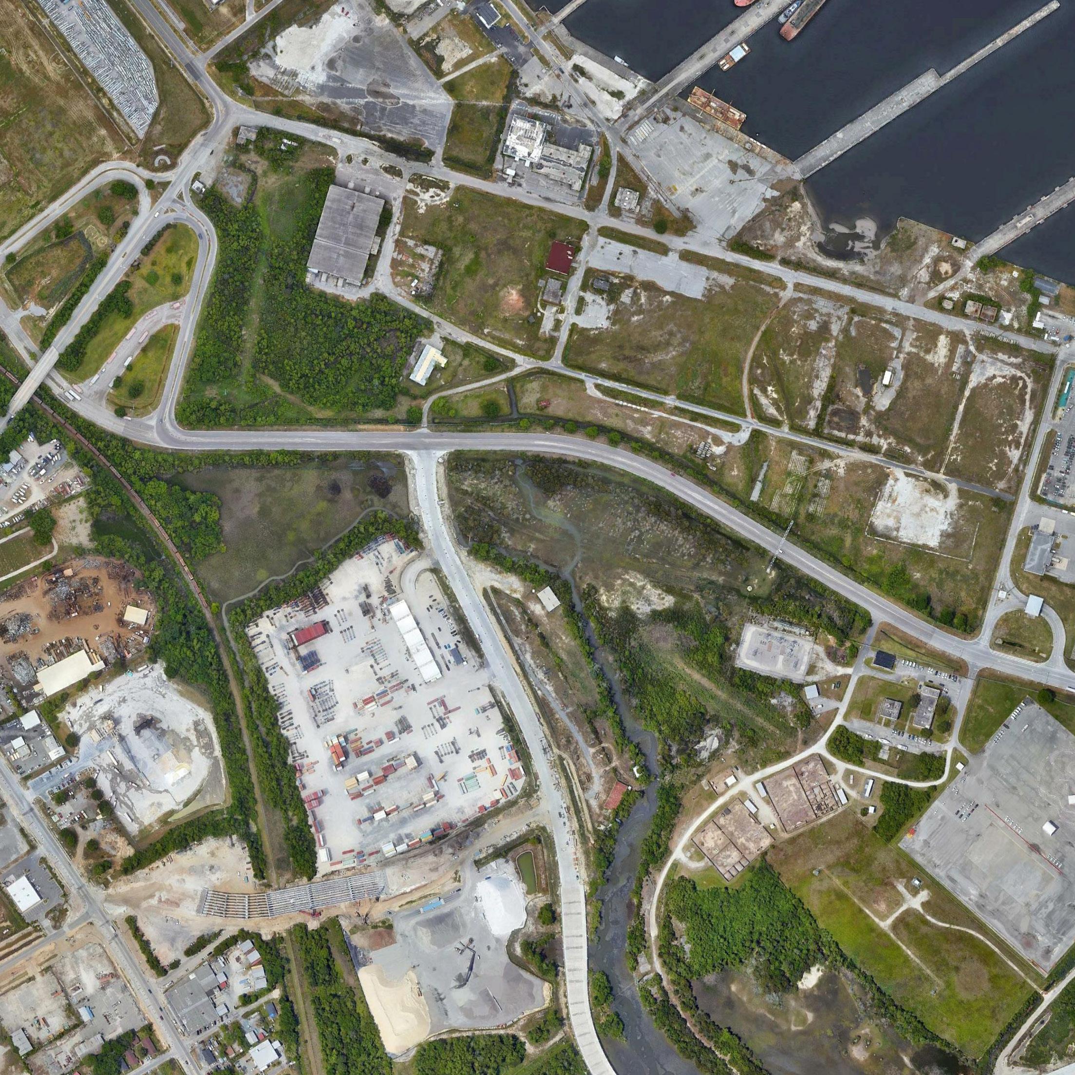
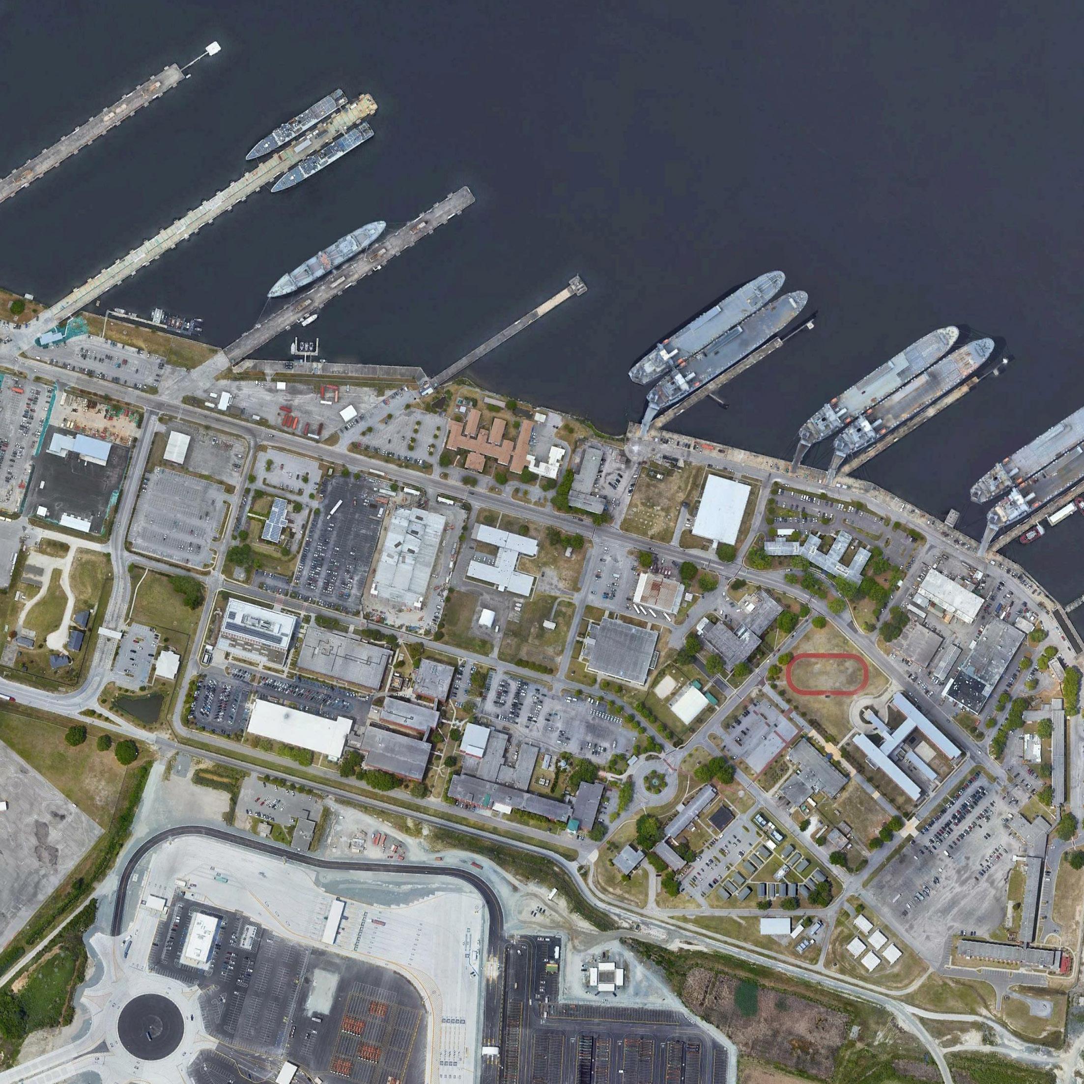
TABLE OF CONTENTS
PROJECT SITE AND AREA OF FOCUS
MULTIFAMILY HOUSING - NICK HAROLD, BAKER RODDEY, LANDON HANNAH...................................................................................... 10
CHILD DEVELOPMENT CENTER - MOLLY PARK, SARAH MILEY................................................................................................................ 28 CHILD DEVELOPMENT CENTER ALTERNATE - MATTHEW BOUREAN....................................................................................................... 46
SECTOR COMMAND - BRITTANY LAPPLE, MICHAELA CHRISMAN............................................................................................................ 52
BASE COMMAND - THALY JIMENEZ, TATE DELUCCIA................................................................................................................................. 70
SUPERTEAM 2
MULTIFAMILY HOUSING - HAILEY KRABBE, LYDIA LEHMAN
CHILD DEVELOPMENT CENTER - JENN DUTT, TAYLOR WAHLER ............................................................................................................114
SECTOR COMMAND - COLIN BLAND, ERIC BELL
BASE COMMAND - CARLEY DOWNS, DANNY CASANOVA, RJ GROSS
vi
...........................................................................................
viii PROJECT BACKGROUND ................................................................................................................. xii STUDIO OVERVIEW ......................................................................................................................... xiv PROJECT PROGRAMMING ............................................................................................................. xvi
SUPERTEAM 1 ................................................................................................................................... 2
................................................................................................................................. 88
..................................................................................................................... 96
..................................................................................................................................... 134
.................................................................................................. 152
INTRODUCTION vii
3 ...............................................................................................................................170
............................................................................................................. 178
...........................................................................................................196
.............................................................................................................218
............................................................................................................................238 SUPERTEAM 4 .............................................................................................................................. 258
COURTNEY
POWELL, ZACHARY STUEMER .................................................................268
LAUREN PRAEUNER...............................................................................................288
GIBSON........................................................................................................................306
................................................................................................................326
SUPERTEAM
MULTIFAMILY HOUSING - ADRIANNA SPENCE, DIEGO BAZZANI
CHILD DEVELOPMENT CENTER - IAN KORDONIS, JOHN OWENS
SECTOR COMMAND - VINCENT CHRISTOPHER II, TUYEN TRAM
BASE COMMAND - XIN GAO, JOSIAH KINNEY, ZACH SI
MULTIFAMILY HOUSING -
WOLFF, GEOFFREY
CHILD DEVELOPMENT CENTER - DANIEL MECCA,
SECTOR COMMAND - SYDNEY PARKER, EMMA
BASE COMMAND - JESSICA LONGHURST, KIMANI GRAYSON


258
SUPERTEAM 4
COURTNEY WOLFF
GEOFFREY POWELL LAUREN PRAEUNER
DANIEL MECCA
JESSICA LONGHURST
KIMANI GRAYSON
ZACHARY STUEMER
SYDNEY PARKER
EMMA GIBSON
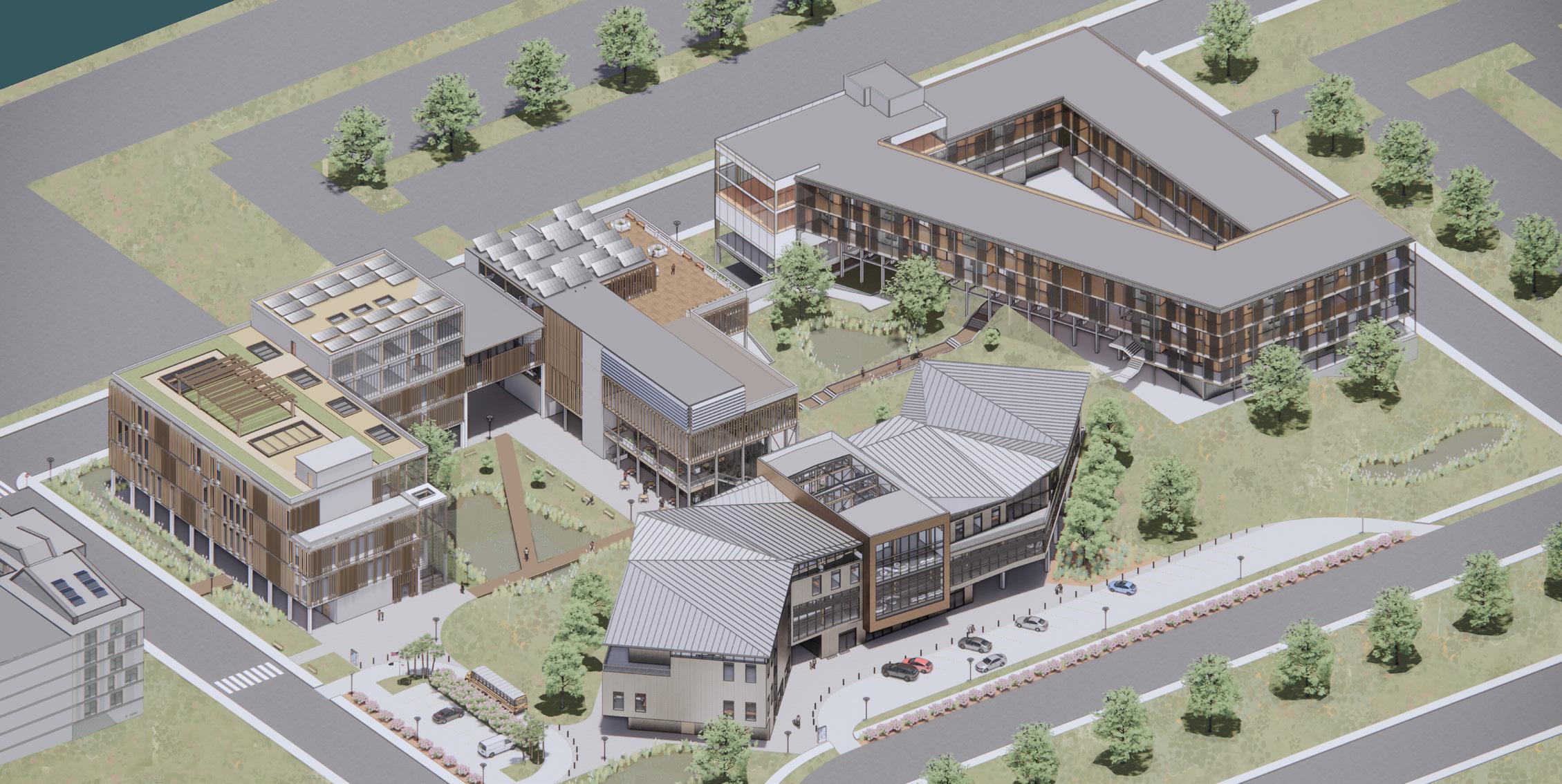
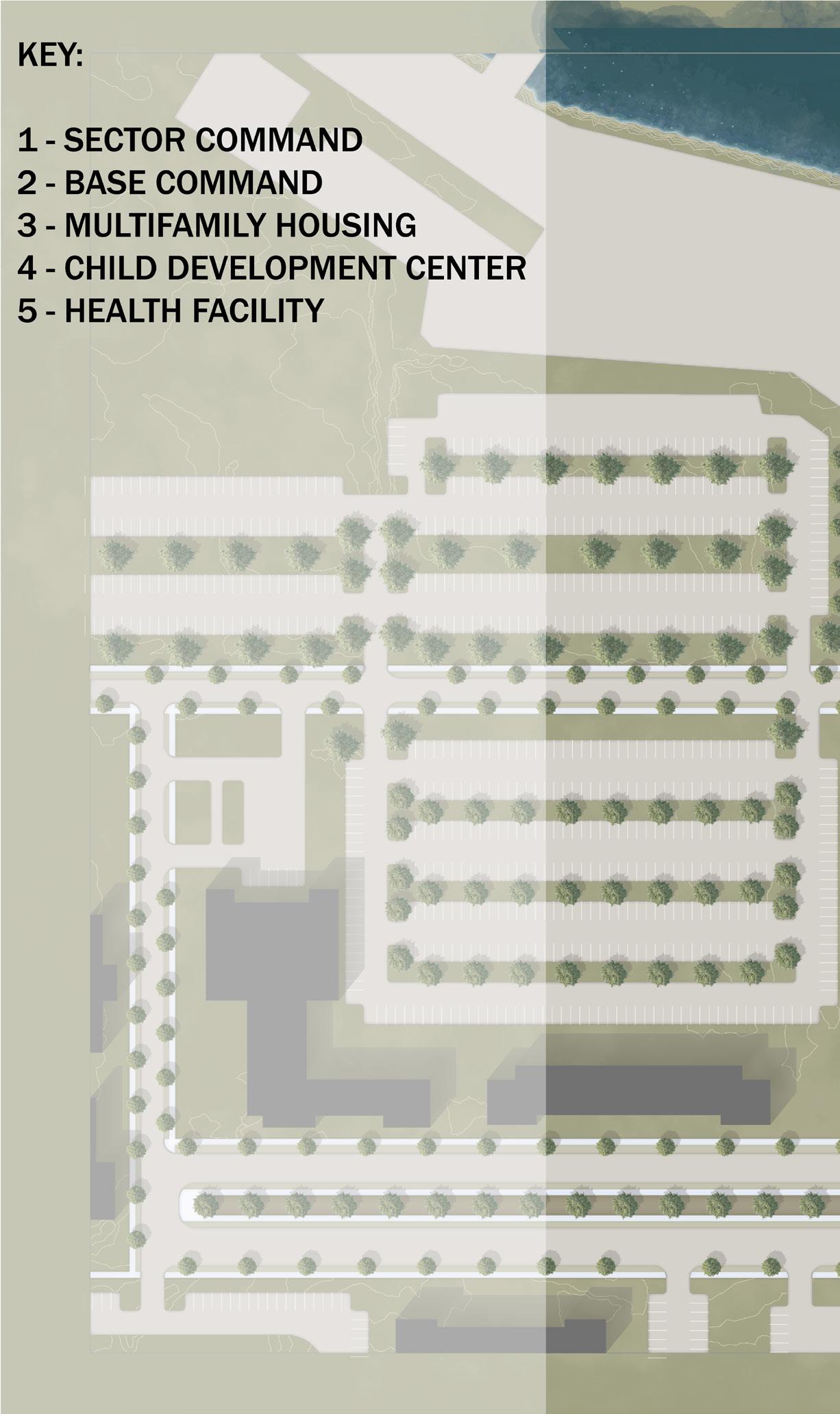
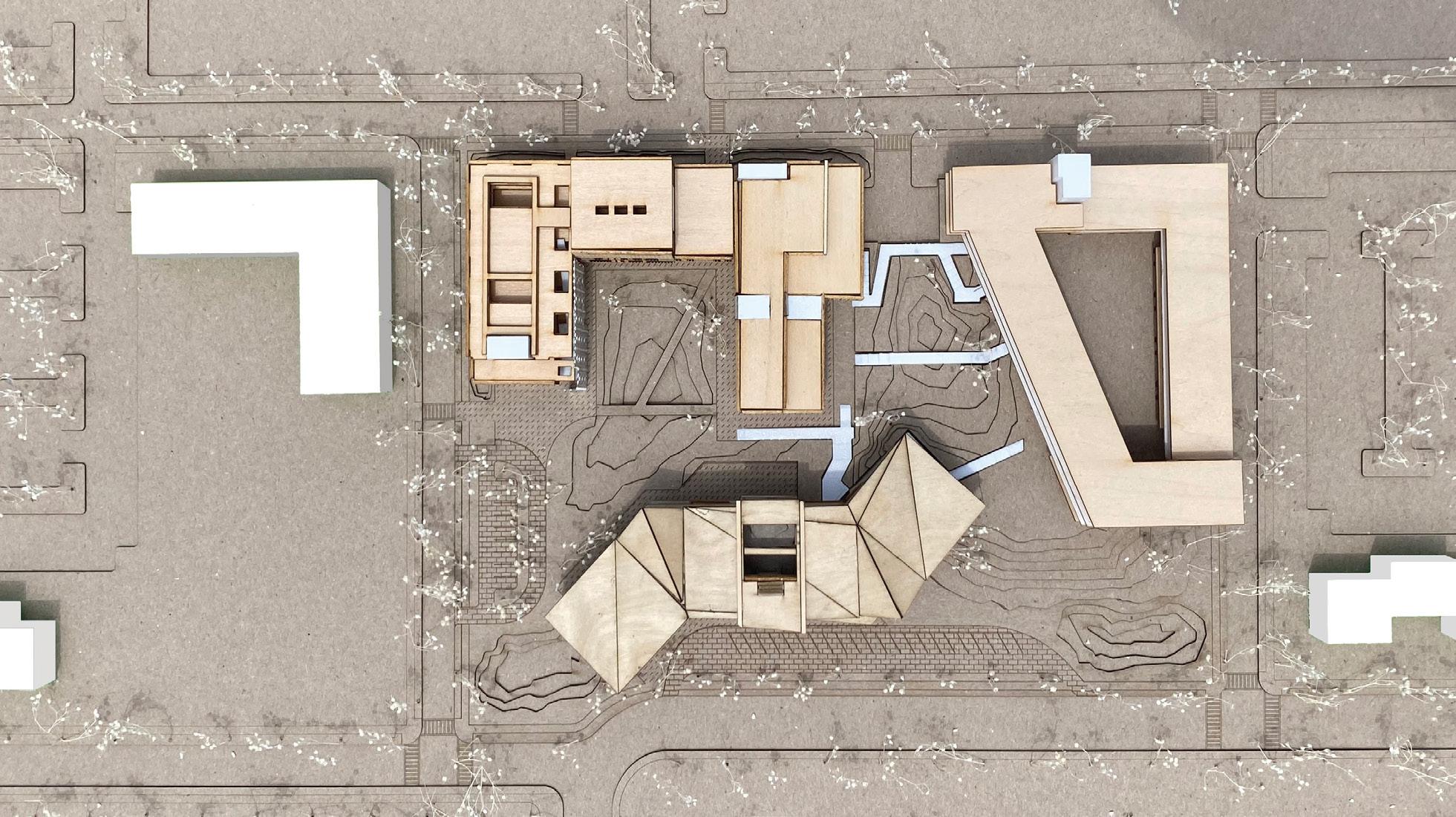
SUB-MASTERPLAN OVERVIEW
MULTI FAMILY HOUSING CHILD DEVELOPMENT SECTOR COMMAND BASE COMMAND
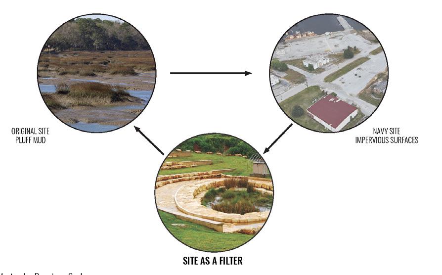
Our design planning sought to address four concerns: unaddressed flooding, parking, a reduction in building frontage, and the role of green space as a filler. We studied our proposal as both a logical next step in the evolution of the site and an ecologically responsible path to the site’s future. The Coast Guard Headquarters in Washington, DC, was used as a precedent case study to develop strategies to filter and manage water, grade the site, and incorporate native landscapes in courtyards. The strategies we relied on the most from this case study were green roof water collection, stormwater gathering areas, filtration systems, and regional landscaping.
When placing buildings on the site, we initially mapped out placement based on adjacencies and incorporating natural green space. The Child Development Center was established on Dyess Avenue as a more formal frontage road to accommodate parent pick-up zones and serve as our neighborhood’s face. The Sector Command and Base Command are placed on the working waterfronts to accommodate workflow, while medical and dental are placed across the street to provide ambulance access. We also manipulated the flat topography to create purposeful high and low points to filter water and people through the site. Throughout this process, we considered the movement of these elements across the site and the connections and relationships that movement created between our different buildings.
At the start of this project, we recognized the minimal importance of working with the floodplain program on the first floor, and manipulating the topography means that parts of the site are elevated above flood levels. In all buildings, any portion of the building below the plane is a concrete structure podium.
259 SUPERTEAM 4
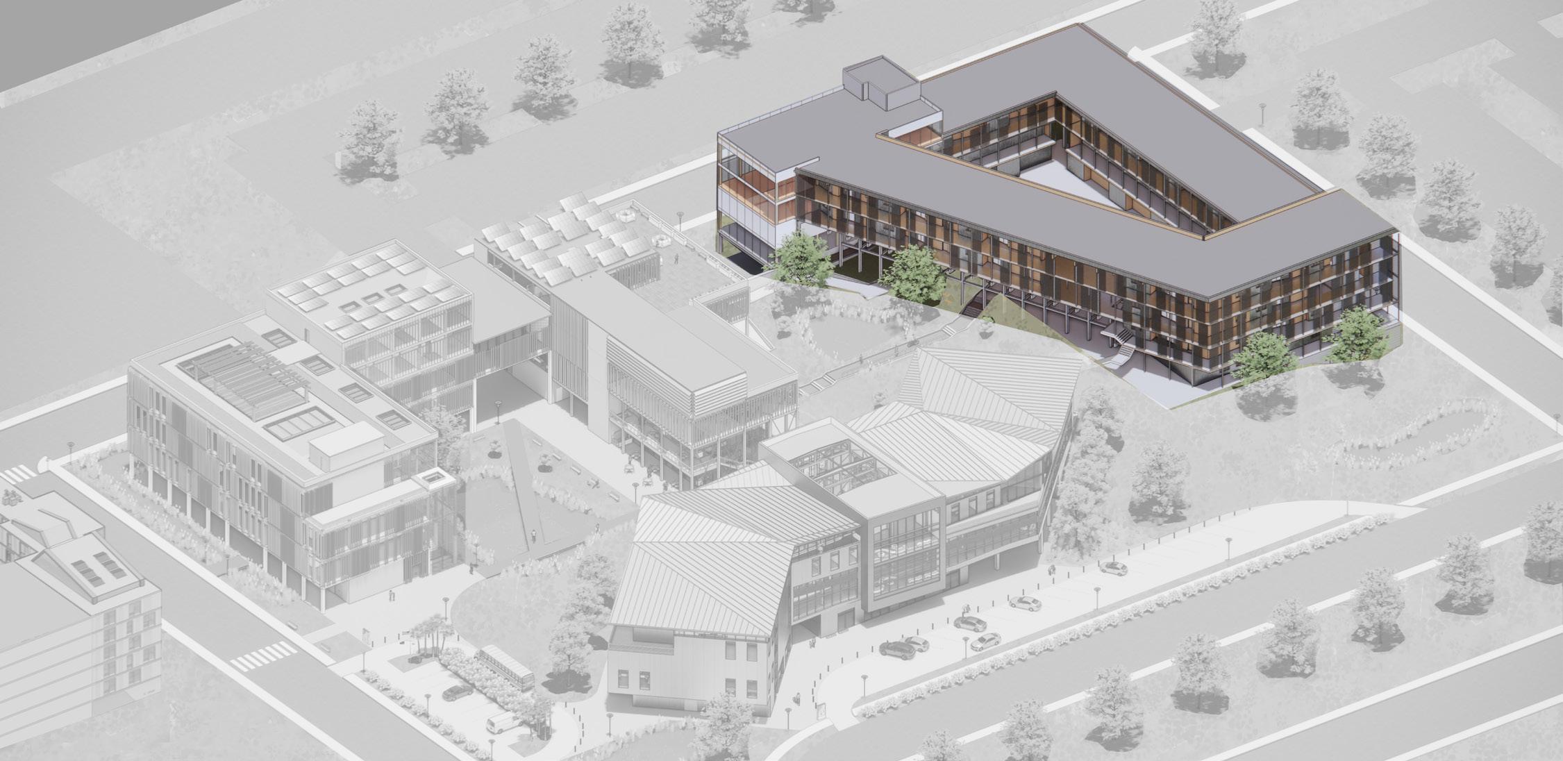
STATES
| BASE CHARLESTON FULL SITE VIEW
UNITED
COAST GUARD
CONCEPT DEVELOPMENT
260 RESEARCH | SITE ANALYSIS
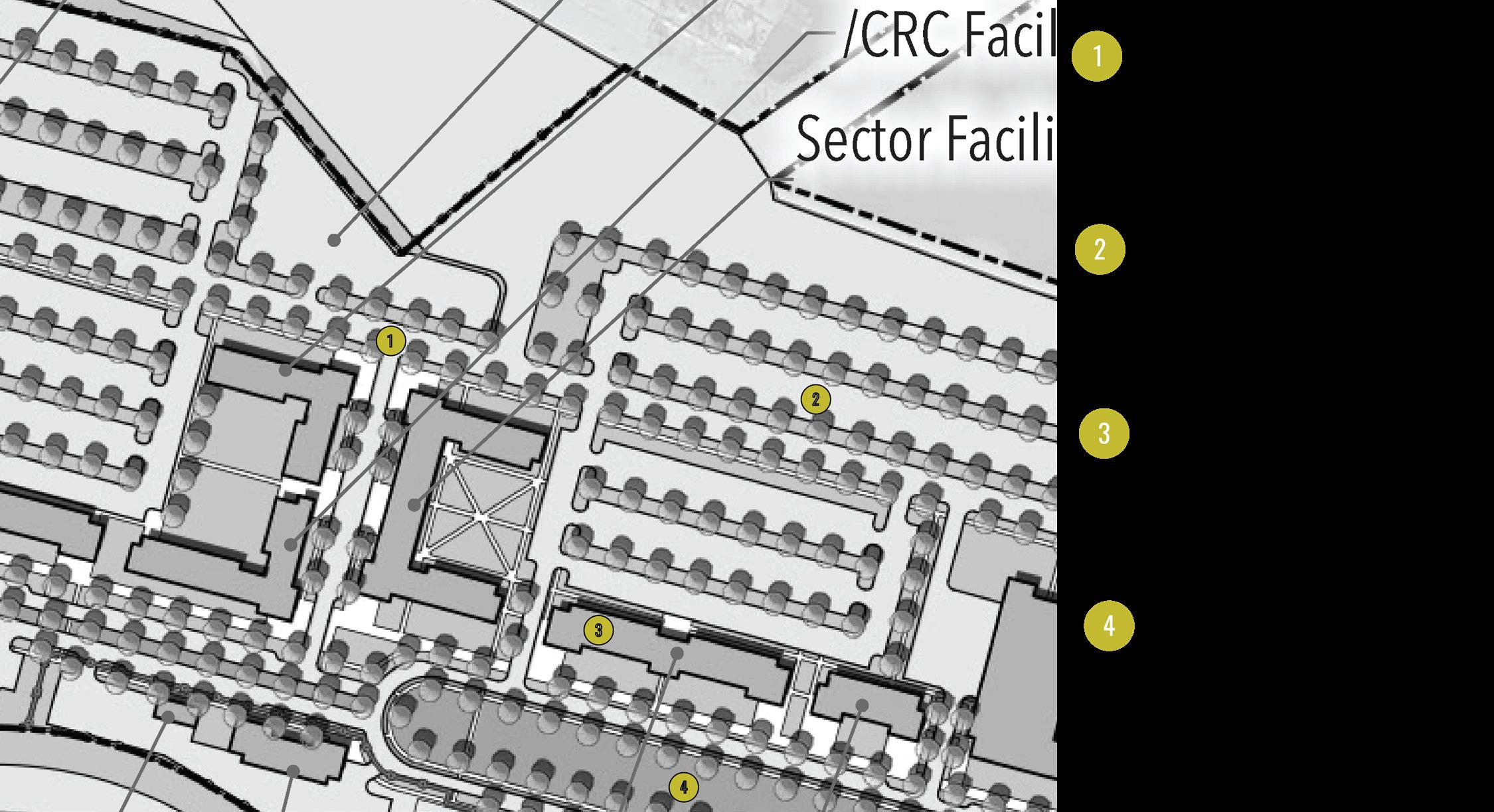
ANNOTATED EXCERPT FROM FLETC/USCG MASTERPLAN
SITE ANALYSIS DIAGRAM
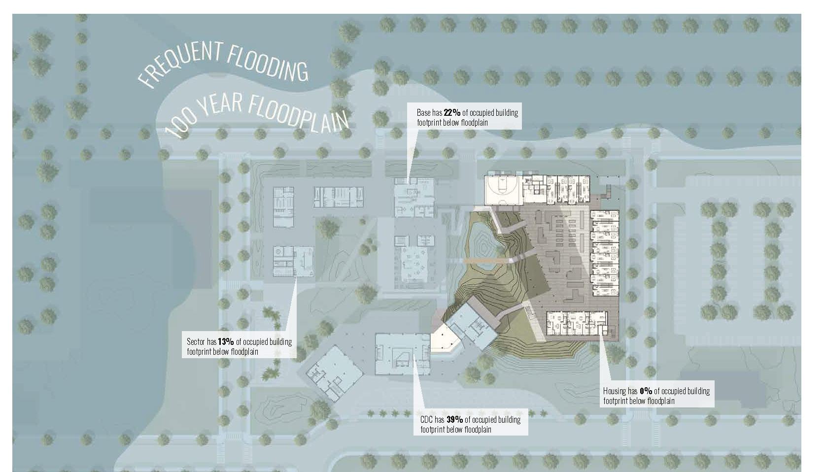
FLOODPLAIN ANALYSIS DIAGRAM
261 SUPERTEAM 4
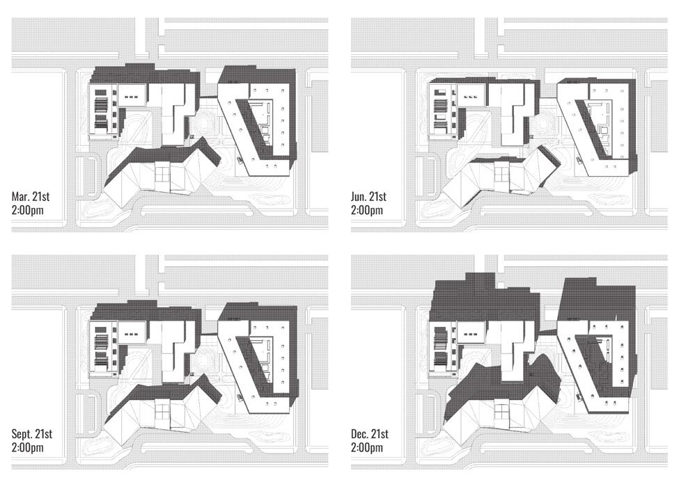
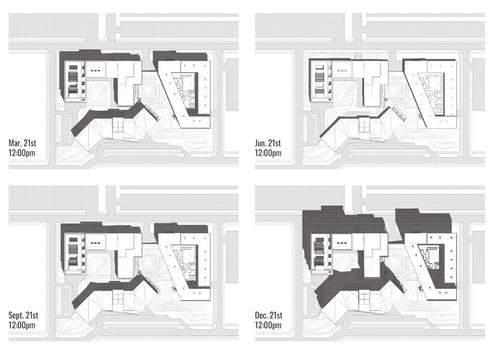
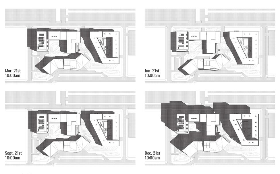
SITE EVOLUTION DIAGRAM
SUN STUDY DIAGRAMS
262 SITE CONDITIOS + SOLUTIONS
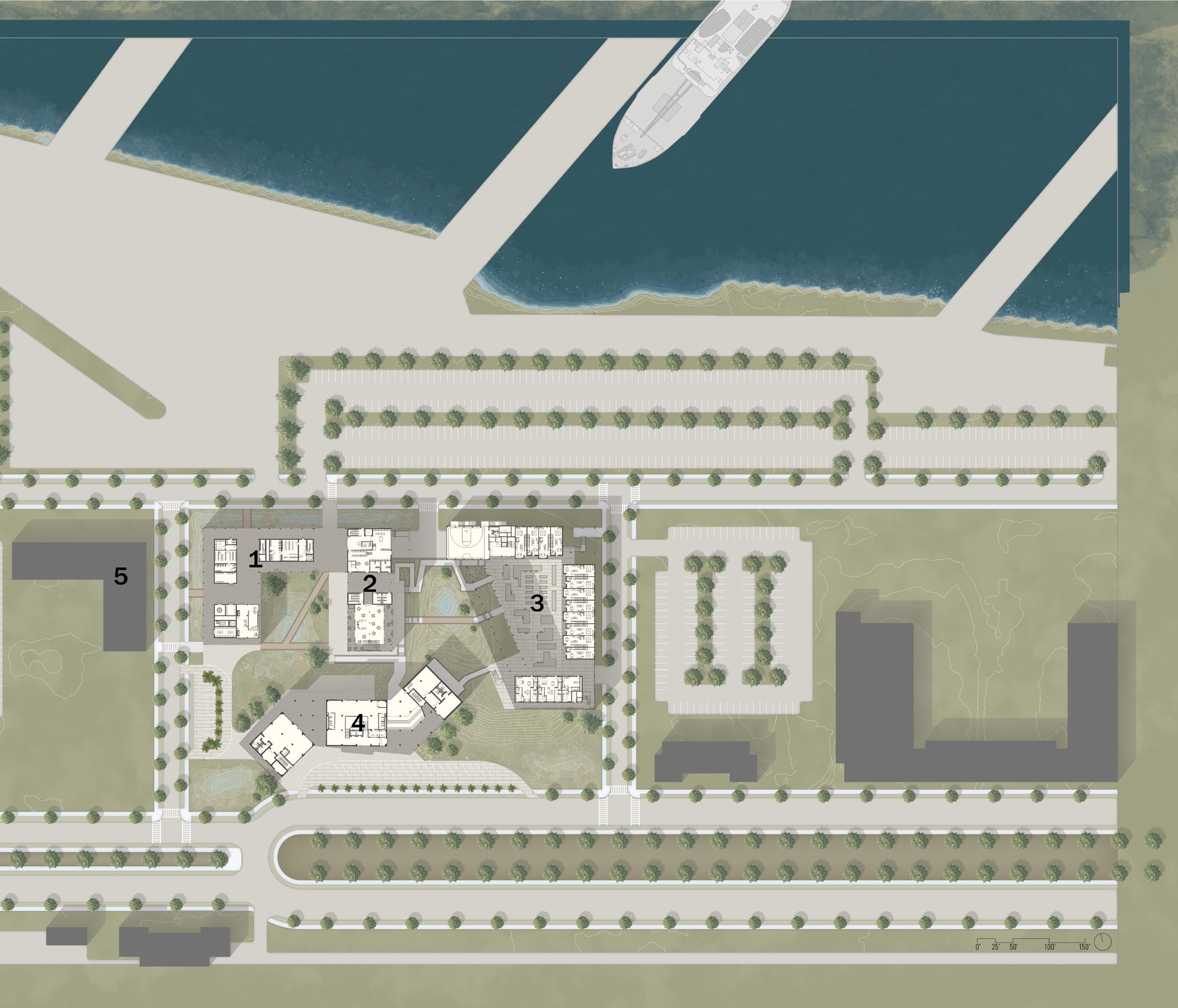
263 SUPERTEAM 4 SITE PLAN
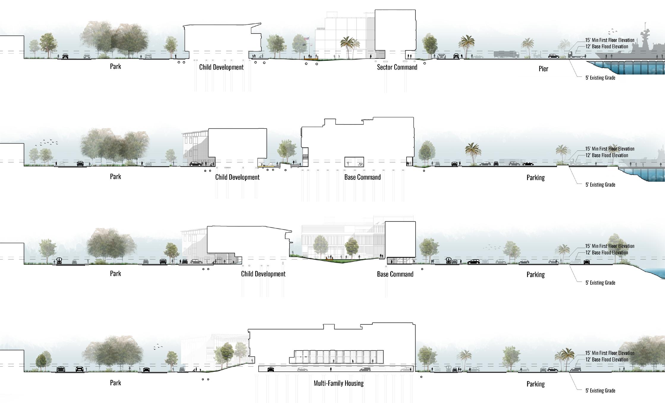
264 SITE SECTIONS
LONGITUDINAL SITE SECTIONS
265 SUPERTEAM 4
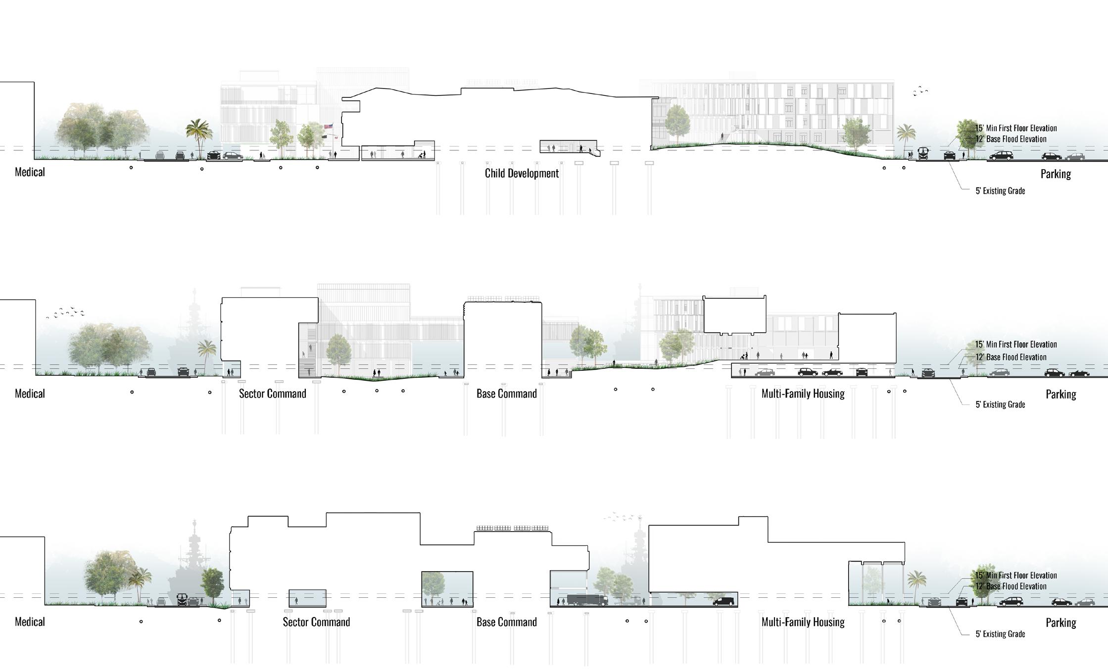
SITE SECTIONS
TRANSVERSAL
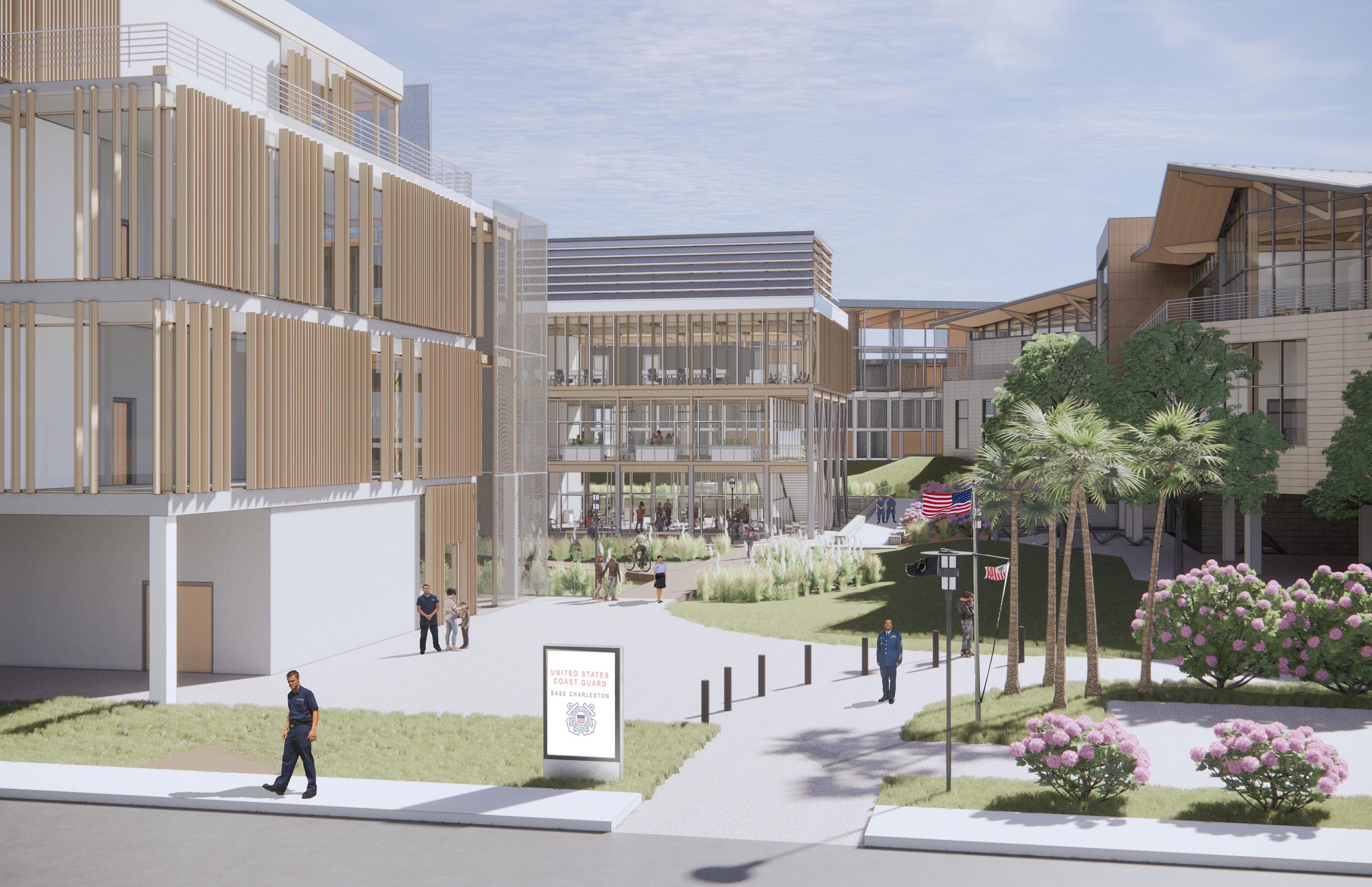
VIEW OF SITE FROM PARKING
266 SITE SECTIONS
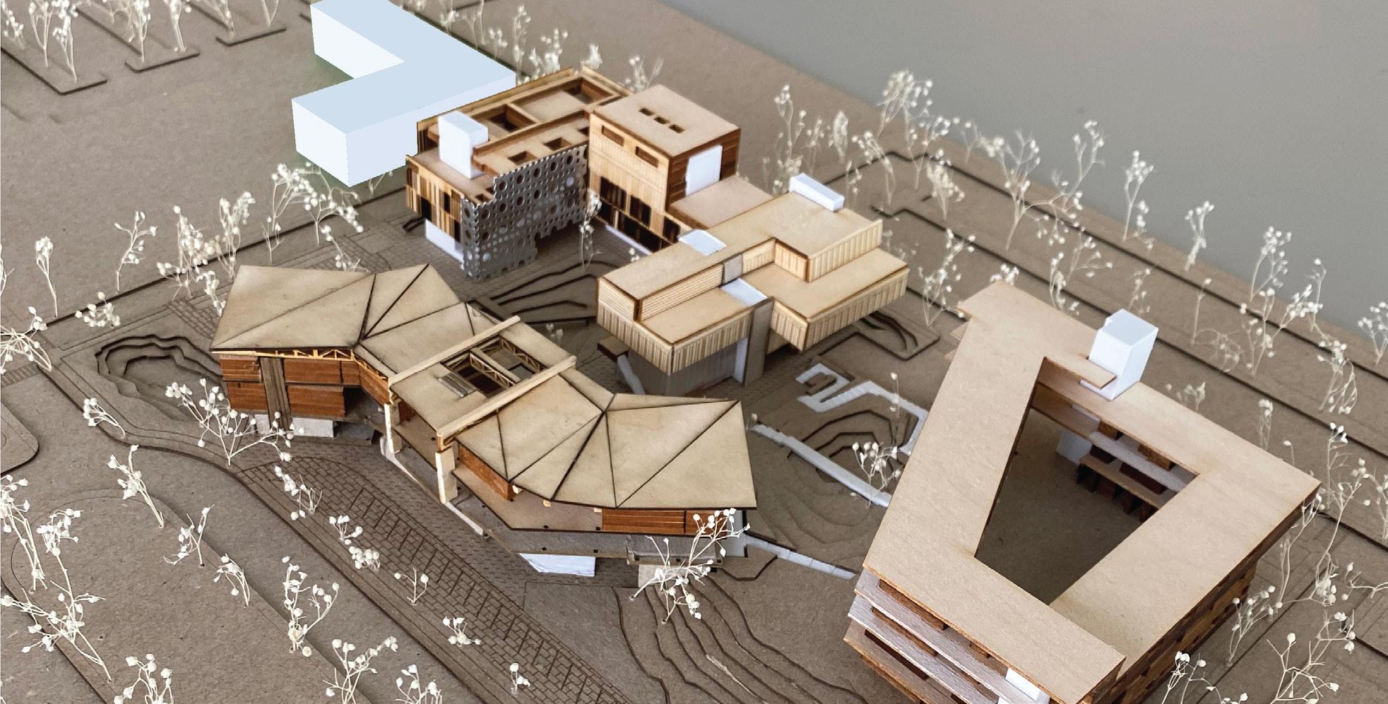
267 SUPERTEAM 4 SITE MODEL
MULTIFAMILY HOUSING
FOR SUPERTEAM 4 SUB-MASTERPLAN
Premise Material Performance + Contexual Experience


Context
Ecological Dwelling
The home is an architecture deeply connected to the person, thus providing an excellent opportunity for influencing an occupant’s way of life. It is an opportunity to redefine behavior patterns by understanding that humans and nature are tied together through processes and time. Usually, integrated systems refer to integrating a building’s mechanical systems with the building’s structural systems, but this project also integrates ecological processes and systems. The Charleston Coast Guard Base is an opportunity to leverage architecture as a mediator in negotiating a more balanced relationship between humans, carbon, energy, and water. The project leverages natural systems as building systems to redefine modern dwelling patterns.
The site’s location and history are of industrial use, but within the proposed United States Coast Guard base, there is a need for multi-family housing. With its domestic use, housing has typically been in opposition to industrial areas in the US since the creation of zoning laws. Additionally, architecture and the USCG are responsible for accounting for the context offered. With this responsibility to the context in mind, how can we negotiate between the domestic and the industrial? This negotiation requires leveraging material qualities to hybridize new and old experiences of these two uses.
One of the main underlying goals of the United States Military is to construct a healthy and effective base operation by building community and fostering camaraderie among military personnel and their families. This ground-up ideology starts at home, and its effects ripple throughout the rest of the base. Thus, it is critical to the design success of a multifamily housing complex at the Charleston Coast Guard Base to consider this fellowship and camaraderie. By orienting the interiors of the units around shared areas, providing large transitional zones between private and public spaces, and integrating a multitude of programmed communal regions throughout, this building will inspire as much engagement as possible among occupants and thus enhance the overall operation of the base
Question
How can we express natural systems through design to motivate and inform occupants’ patterns of being towards a more sustainable and ecologically integrated way of life?
How can the performance of materials be used to provide for contexual experiences?
How can the building effectively engage the user and foster community to enhance the overall experience of the occupant?
268 MULTIFAMILY HOUSING |
+
+
COURTNEY WOLFF
GEOFFREY POWELL
ZACHARY STUEMER
COURTNEY WOLFF GEOFFREY POWELL
Communal + Engaging
ZACHARY STUEMER
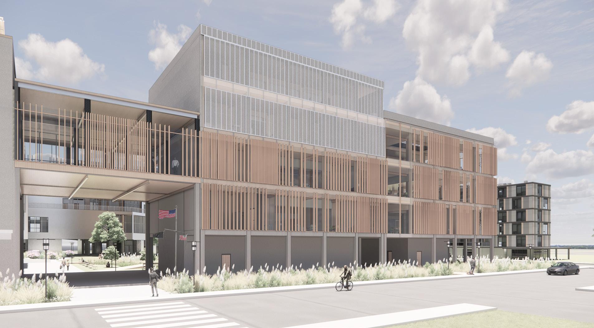
Working within the design context of the Coast Guard Base Charleston along the Cooper River with the typology of multi-family housing, our project merges three premises. The project represents “ecological dwelling,” spaces that are “communal and engaging,” and an overall architecture about “material performance and contextual experience.” The result is the primary combined goal of creating a building designed to provide an experience that engages the user with the architecture, their community, and their environment. Our multi-family housing building has 82 bedrooms within 36 units, approximately 76,000 sq. ft. In addition to the dwelling units, there is an indoor sports court, workout room, laundry, community garden, and community room.
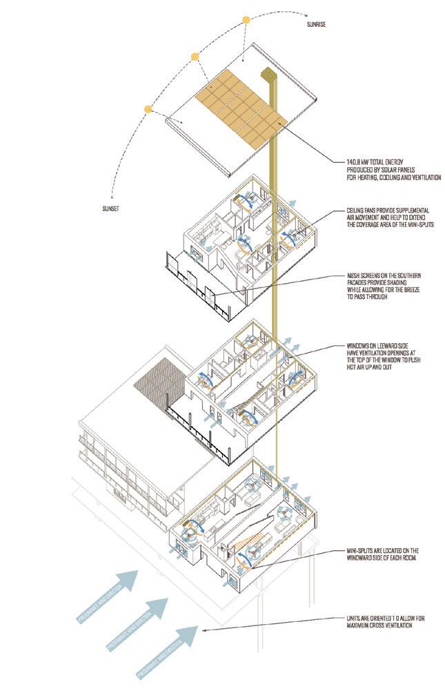
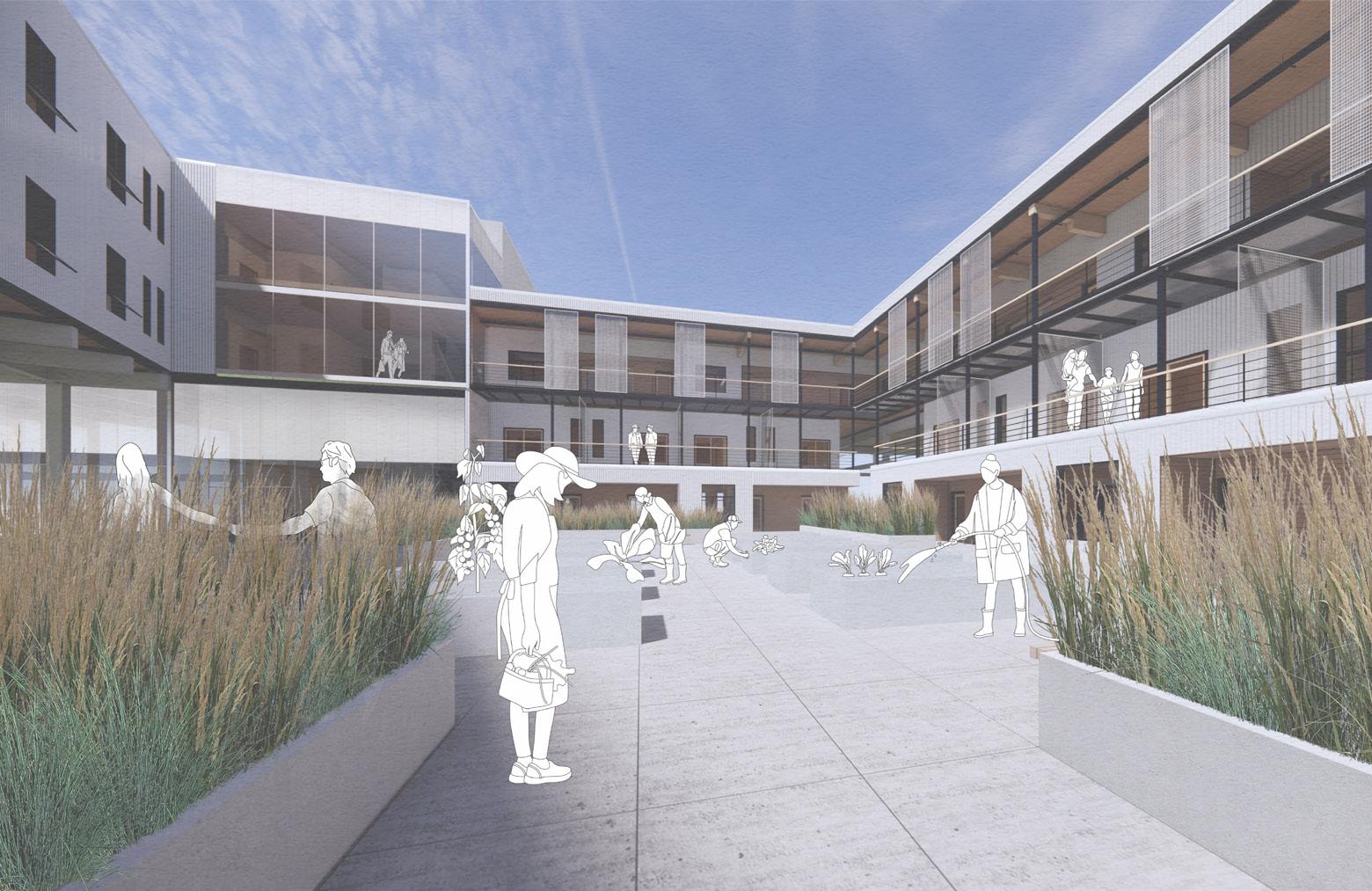
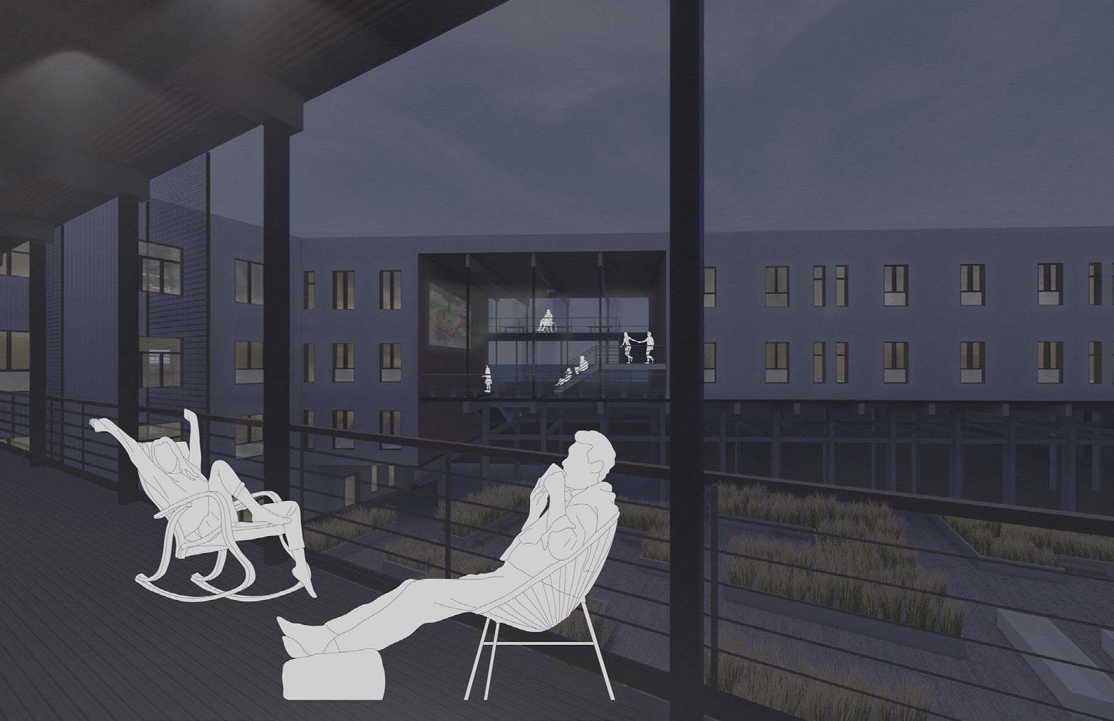
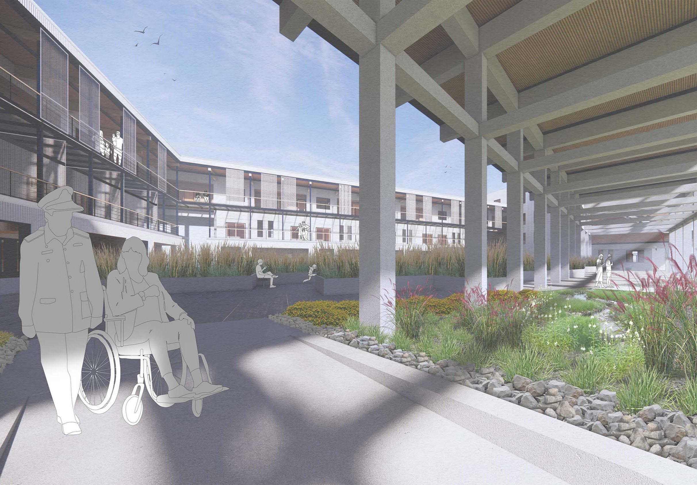
Water, wind, and sun are major driving factors for this design proposal. The design also embraces the constraints of flooding and sea level rise at both the site and building scale. Importantly, our design handles the high base flood elevation issue while maintaining a pedestrian experience from the ground level. This goal is achieved by creating a hill composed of soil displaced from other constructions, etched with paths around natively vegetated bioswales and filter strips. These paths terminate at a shared courtyard space that harbors the community garden.
Overall, the design proposal we have created is a building designed directly to the site context and the local climate while simultaneously providing an experience that engages the user with the architecture, their community, and the environment. We achieve our design intent by implementing appropriate materials that protect the construction from flood damage and create a habitable atmosphere, integrating shared spaces to foster community, and incorporating design details that inspire the user to embrace their surroundings.
269 SUPERTEAM 4
SITE
MULTIFAMILY HOUSING LOCATION ON
BUILDING FORM DIAGRAM
BUILDING FORM
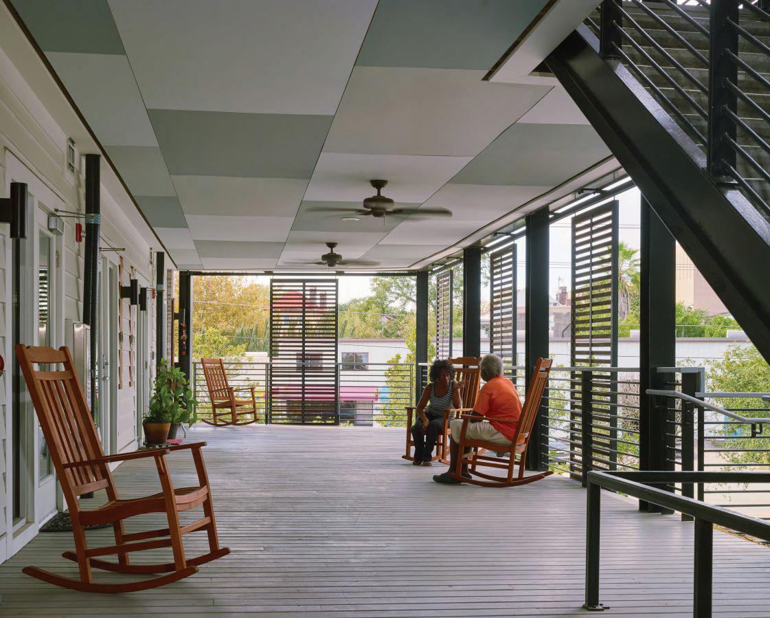
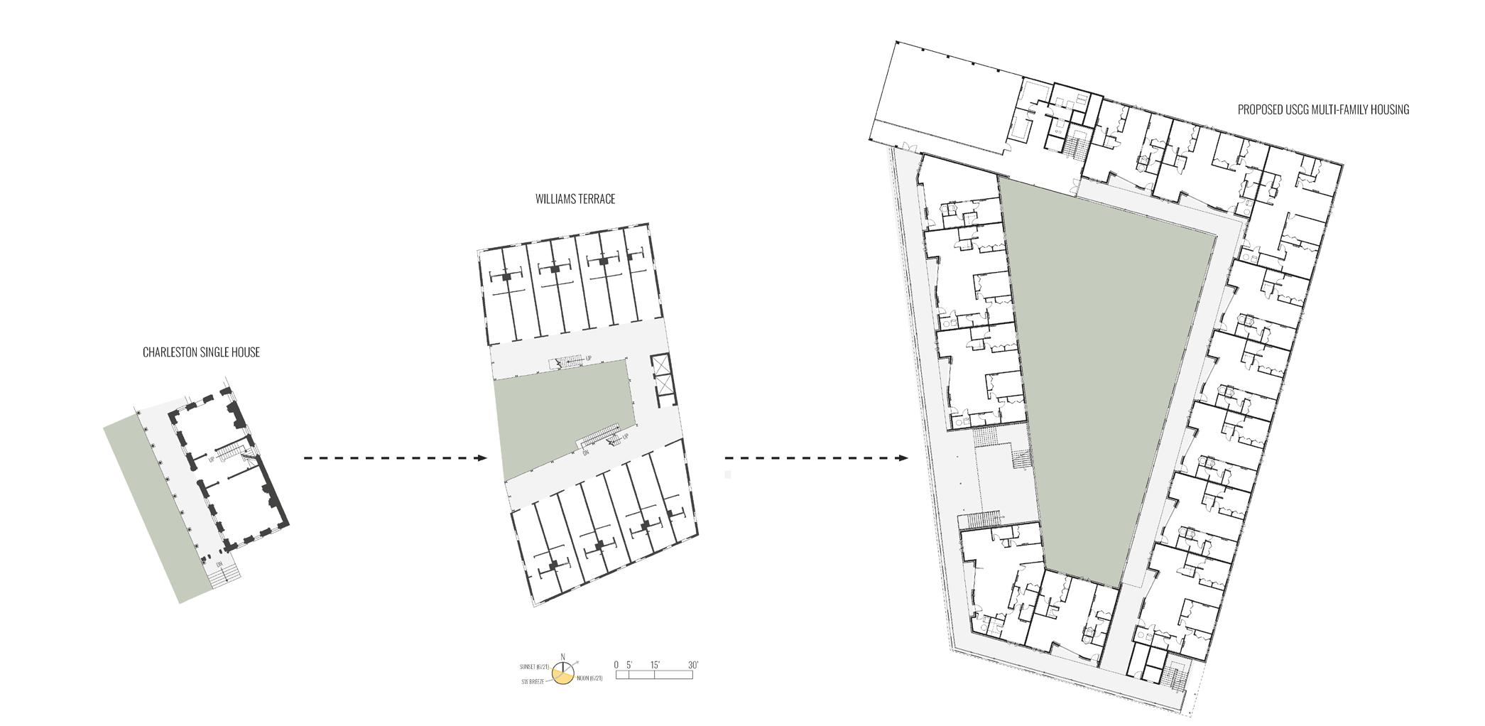
Our project starts with the base of a traditional courtyard apartment typology to prioritize community space. We manipulated the design’s form to respond to environmental and social conditions. At the bridge connection, our team oriented the units to face the southwest breeze and used the circulation to create shade. The local precedent of the Charleston single house and its contemporary derivatives informed this decision immensely. Following this local source, circulation space is composed of exterior egress balconies, which, in addition to providing community space, allow for natural ventilation through the units and offer a significant overhang for shading the units below.
270
TRADITIONAL COURTYARD APARTMENT EARTHWORKS ELEVATE ROTATE PARKING PODIUM CONNECT Start with a courtyard typology because of the communal aspect Create a hill hiding the parking garage that faces the interior of the site Raise the whole building as a response to the base flood elevation Angle the SW corner to capture wind for natural ventilation Integrate both public and private parking to maintain a sidewalk presence Raise the section that faces the rest of the site to create pedestrian connections COOPERRIVER SUMMERSOLSTICE June 21 5:17 AM WINTERSOLSTICE 5:13 PM December 21 7:23 AM 6:57 PM 1:00 PM E N ENDOFOVERHEATINGPERIOD 6:01 PM October 1 6:18 AM W S SITE DIAGRAM
SUN AND WIND AXONOMETRIC DIAGRAM MULTIFAMILY HOUSING | COURTNEY WOLFF + GEOFFREY POWELL + ZACHARY STUEMER
WILLIAMS TERRACE APARTMENTS
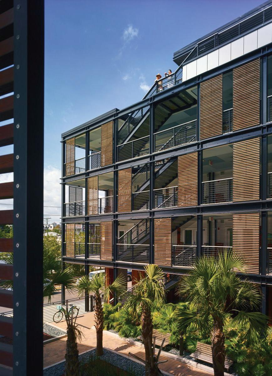
Charleston, South Carolina
KEY CONCEPTS
• Critical application of regional vernacular that responds to local climate
• Similar life safety and code conditions; R-2 over a S-2 podium
• Varied types of community spaces ranging between public and private
CASE STUDY
271 SUPERTEAM 3 PRECEDENT
PROGRESSION DIAGRAM
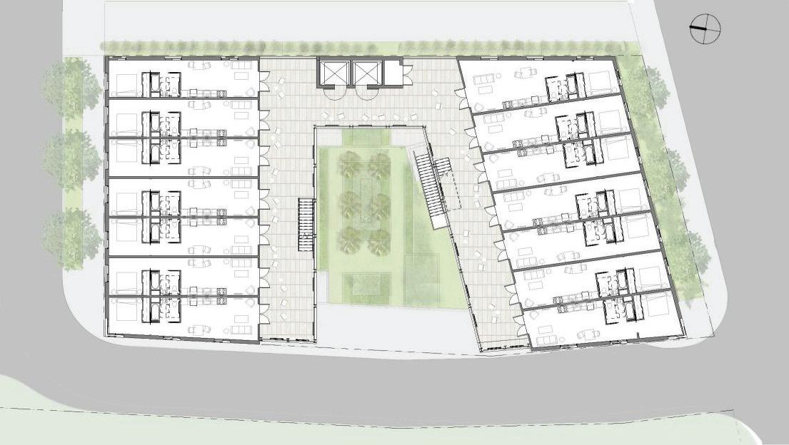
FLOOR PLAN
McMillian Pazden Smith and David Baker Architects
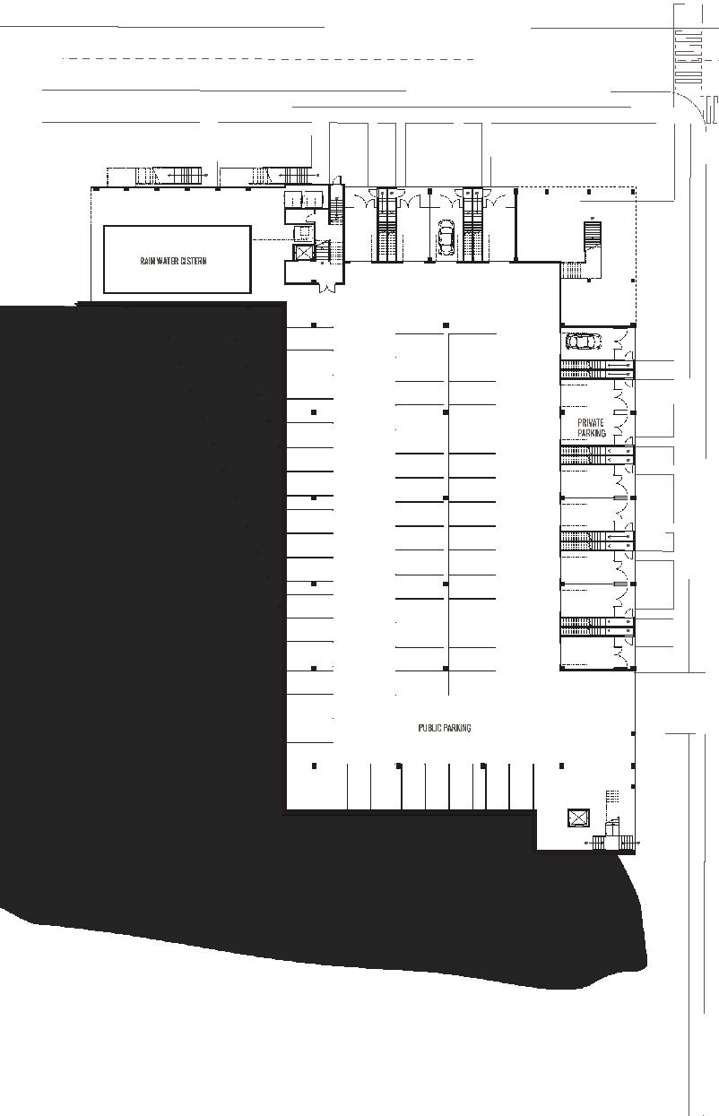
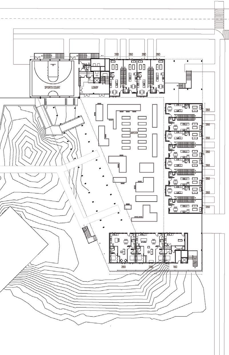
272 FLOOR PLAN GROUND FLOOR A A B B TOTAL SQ FT: 33,149 STANDARD PARKING SPACES: 58 ACCESSIBLE PARKING SPACES: 6 FLOOR PLAN FLOOR 1 A A B B TOTAL SQ FT: 15,352 TOTAL DWELLING UNITS: 15 TOTAL BEDROOMS: 6 COURTYARD COMMUNITY ROOM SPORTS COURT WORKOUT ROOM PORCHES MULTIFAMILY HOUSING | COURTNEY WOLFF + GEOFFREY POWELL + ZACHARY STUEMER COMMUNITY PROGRAM DIAGRAM GROUND LEVEL FLOOR PLAN LEVEL 1 FLOOR PLAN
FLOOR PLAN ROOF
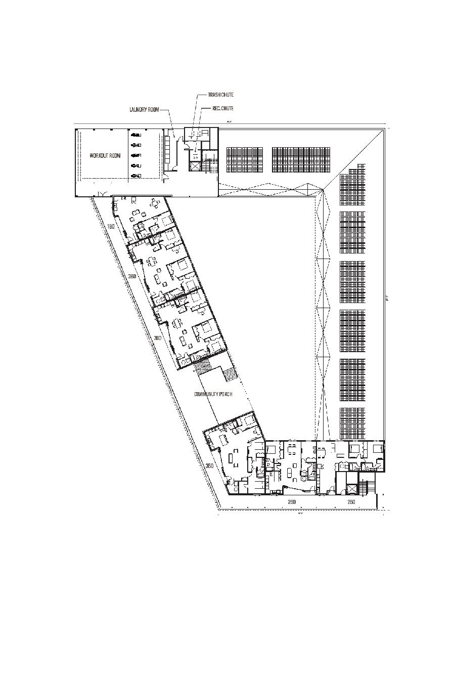
273 SUPERTEAM 4 A B B TOTAL SQ FT: 15,088 TOTAL DWELLING UNITS: 19 TOTAL BEDROOMS: 31
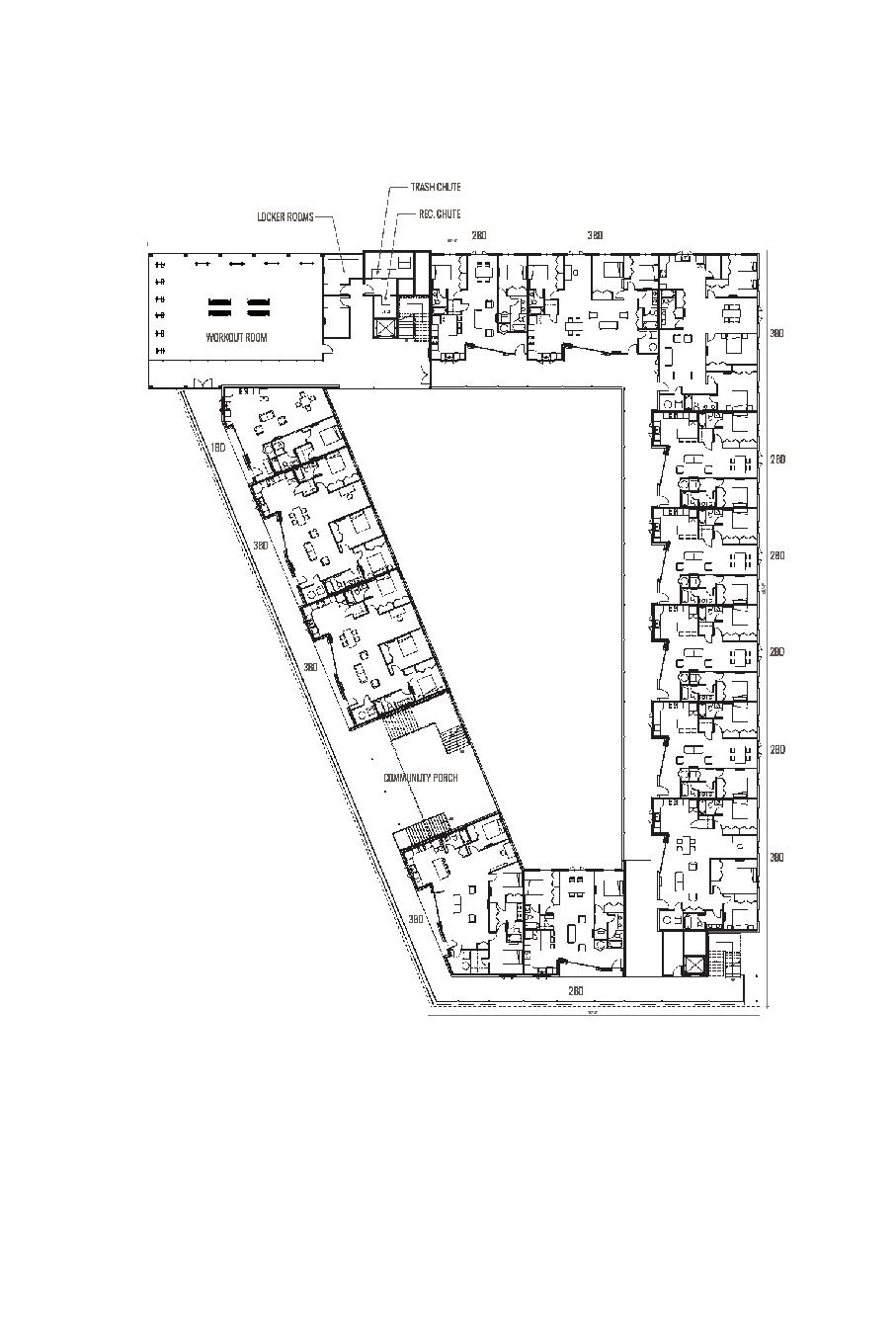
A A B B TOTAL SQ FT: 30,045 TOTAL DWELLING UNITS: 13 TOTAL BEDROOMS: 31
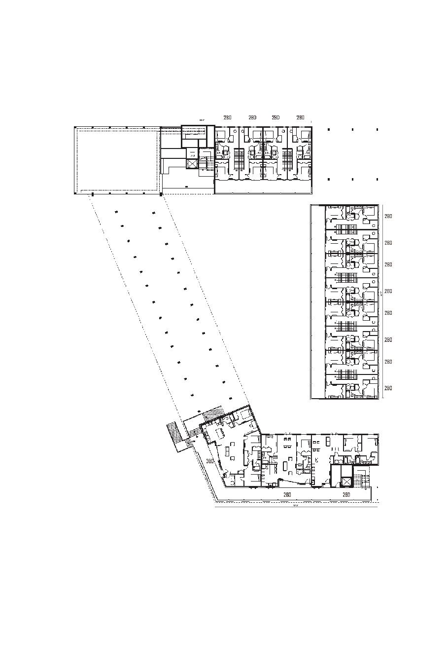
A A B B TOTAL SQ FT: 15,489 TOTAL DWELLING UNITS: 6 TOTAL BEDROOMS: 14
A A B B
FLOOR PLAN FLOOR 3
FLOOR PLAN FLOOR 4
LEVEL 2 FLOOR PLAN LEVEL 3 FLOOR PLAN LEVEL 4 FLOOR PLAN ROOF PLAN
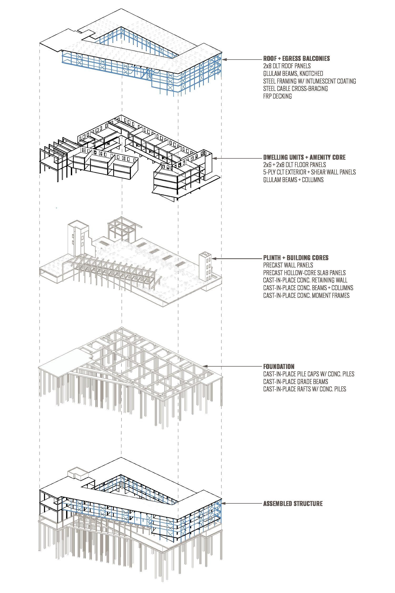
STRUCTURE
STRUCTURE EXPLODED AXONOMETRIC DIAGRAM
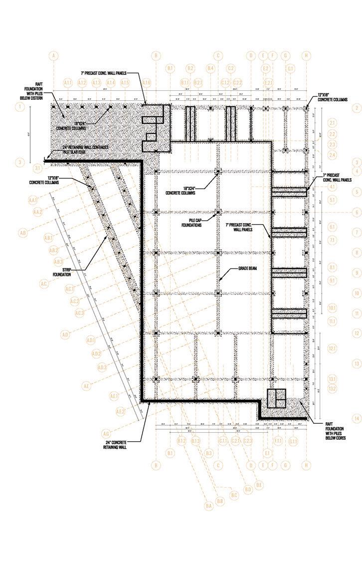
GROUND LEVEL STRUCTURAL PLAN
STRUCTURAL PLAN FLOOR 1
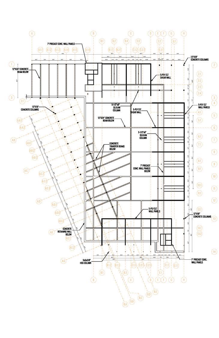
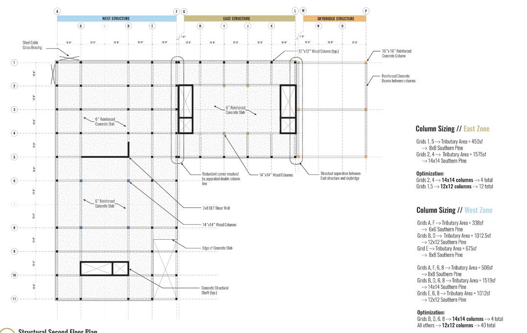
LEVEL 1 STRUCTURAL PLAN
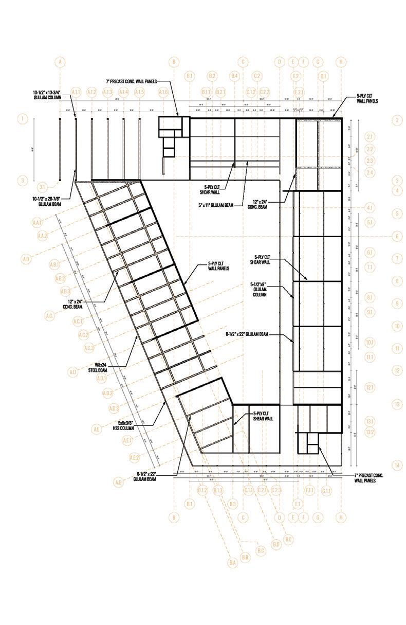
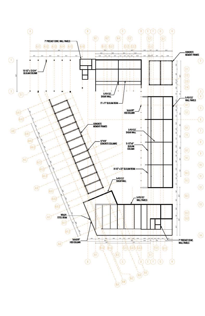
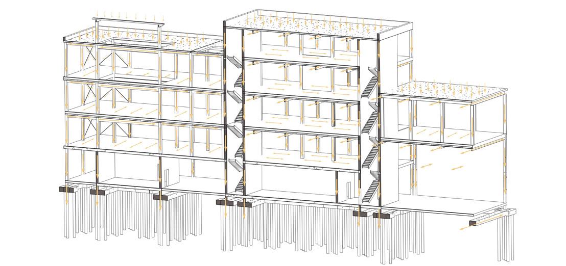
The expression and experience of exterior egress balconies determined our structural system. A steel frame hanging from the roof’s glulam beams, made possible by the back span of the beams, supports the balconies. DLT floors supported by a network of CLT walls, glulam beams, and columns comprise adjacent dwelling units. These units, in turn, are supported by a combination of concrete beams, columns, and a hollow core slab. Below the concrete podium, foundations contain piles to negotiate the poor soil conditions.
274
MULTIFAMILY HOUSING | COURTNEY WOLFF + GEOFFREY POWELL + ZACHARY STUEMER
STRUCTURAL PLAN FLOOR 2
STRUCTURAL PLAN FLOOR 3
B A.1.5 A.1.4 A.1.3 A.1.2 A.1.1
C.2
10'
A.A.1 A.B A.B.1 A.B.2 A.B.3 A.C. A.C.1 A.C.2 A.C.3 A.D
E.2
10"
A.E.1 A.E.2
A.G
13'
8-1/2” 33” GLULAM BEAM, KNOTCHED TO 8-1/2” 11” 5-PLY CLT SHEAR WALL BELOW
B.1 B.1
8-1/2”
B.4 B.2 B.1.3 B
B.1.2
A.1.6 B.A
5-PLY CLT WALL PANELS
A B.C B.D
C C
A.D.1 A.D.2 A.D.3 A.E B.E
C.2.1
C.2.3 C.1.1 B.3
D D
G.1 E.2.1 B.B
2.1 2.3
2 2.2 2.4 4 3.1 6
7” PRECAST CONC. WALL PANELS 7” PRECAST CONC.
G.1.1 F.1.1 E.1
H G G
3 3 A.A.2
5 8 9 10 11 12 13.1
B.1.1 B.2.1 C.1.2 C.2.2 4.1 5.1 6.1 7.1 8.1 9.1 10.1 11.1 12.1 14
13 13.2 H
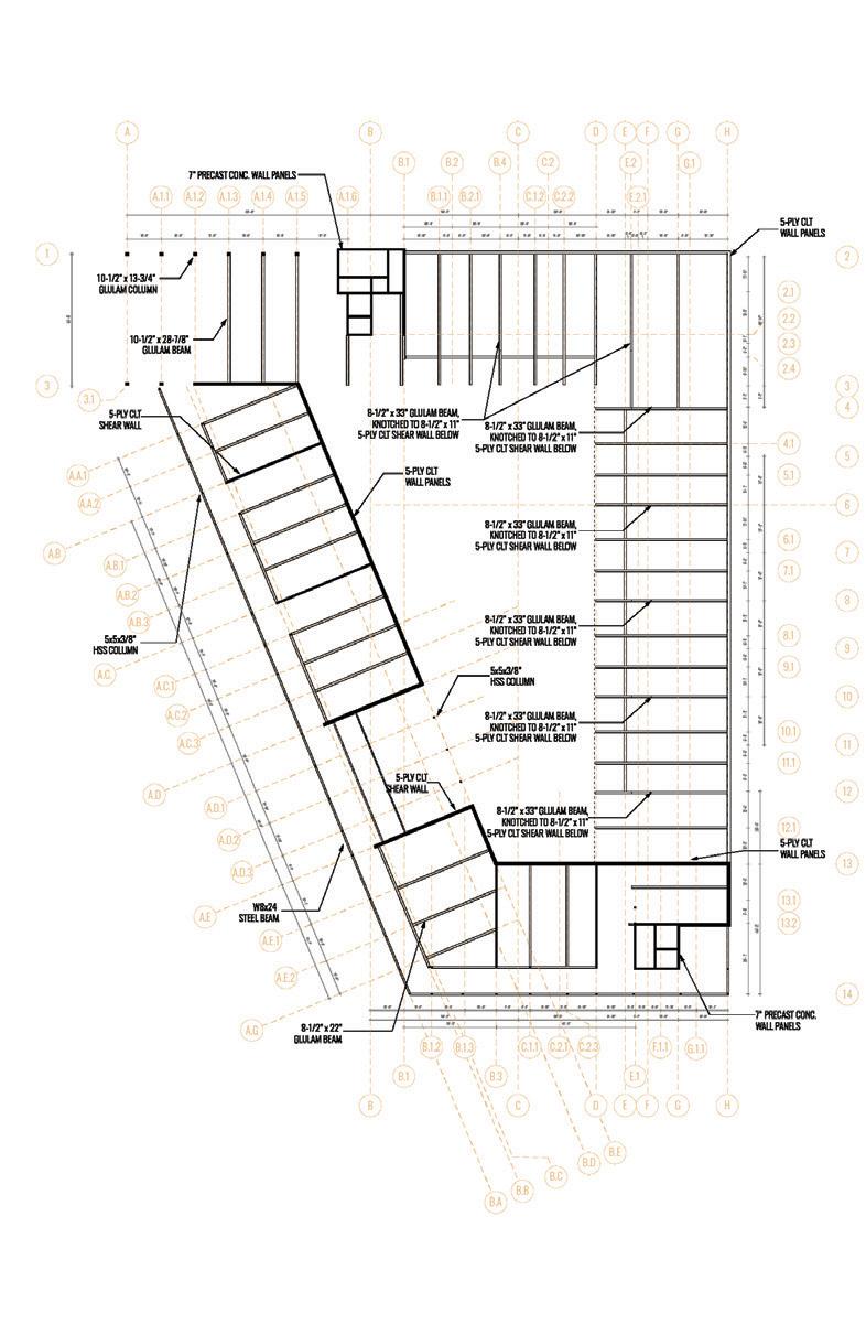
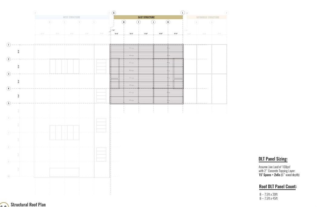
WALL PANELS BELOW 33” GLULAM BEAM, KNOTCHED TO 8-1/2” 11” 5-PLY CLT SHEAR WALL BELOW 8-1/2” 33” GLULAM BEAM, KNOTCHED TO 8-1/2” 11” 8-1/2” 33” GLULAM BEAM, KNOTCHED TO 8-1/2” 11” 5-PLY CLT SHEAR WALL BELOW 8-1/2” 33” GLULAM BEAM, KNOTCHED TO 8-1/2” 11” 5-PLY CLT SHEAR WALL BELOW 8-1/2” 33” GLULAM BEAM, KNOTCHED TO 8-1/2” x 11” 5-PLY CLT SHEAR WALL BELOW STRUCTURAL PLAN ROOF LEVEL 2 STRUCTURAL PLAN LEVEL 4 STRUCTURAL PLAN LEVEL 3 STRUCTURAL PLAN ROOF STRUCTURAL PLAN
275 SUPERTEAM 4
STRUCTURAL PLAN FLOOR 4
10-1/2” 28-7/8” GLULAM BEAM 8-1/2” 22” GLULAM BEAM 5-PLY CLT WALL PANELS
17 LEVEL 32'-0" to 34'-0" 28 ROOF 8-1/2" 28-7/8" GLULAM BEAM SYP 44'-6" SMARTLAM (DOTHAN, AL) LOWER ROOF 8-1/2" 33" GLULAM BEAM (KNOTCHED TO 8-1/2" 11") SYP 44'-6" 21 SMARTLAM (DOTHAN, AL) ROOF 44'-6" 24 LEVEL 10-1/2" 28-7/8" GLULAM BEAM SYP 44'-0" SMARTLAM (DOTHAN, AL) LEVEL 44'-0" ROOF 44'-0"
277 SUPERTEAM 4
MASS TIMBER LOCATION PRODUCT/ELEMENT SPECIES QUANTITY (LFT) TYP. HEIGHT (FT) THICKNESS (IN) MANUFACTURER LEVEL 5-PLY CLT WALL PANEL SYP 719'-0" 12'-0" 6" SMARTLAM (DOTHAN, AL) LEVEL 625'-0" LEVEL 1070'-0" LEVEL 436'-0" ENGINEERED WOOD LOCATION PRODUCT/ELEMENT SPECIES LENGTH (FT) # OF ELEMENTS MANUFACTURER LEVEL 5-1/2" 9" GLULAM COL. SYP 24'-0" 28 SMARTLAM (DOTHAN, AL) LEVEL 12'-0" 13 LEVEL LEVEL 8-1/2" 11" GLULAM COL. SYP 24'-0" SMARTLAM (DOTHAN, AL) LEVEL 10-1/2" 13-3/4" GLULAM COL. SYP 24'-0" 13 SMARTLAM (DOTHAN, AL) LEVEL 9 LEVEL 5" 11" GLULAM BEAM SYP 15'-0" to 16'-0" 24 SMARTLAM (DOTHAN, AL) LEVEL 24 LEVEL 8-1/2" 22" GLULAM BEAM SYP 20'-6" to 34'-0" 13 SMARTLAM (DOTHAN, AL) LEVEL 32'-0" to 34'-0"
STRUCTURAL STEEL LOCATION PRODUCT/ELEMENT FINISH LENGTH (FT) # OF ELEMENTS SUPPLIER LEVEL HSS 5x5x3/8 INTUMESCENT COATING 12'-0" 13 TBD LEVEL 33 LEVEL 55 LEVEL 32 LEVEL W 8x24 INTUMESCENT COATING 7'-6" to 12'-0" 16 TBD LEVEL 53 LEVEL 29 LEVEL W 14x34 INTUMESCENT COATING 23'-0" to 35'-0" TBD LEVEL WT 5x11 INTUMESCENT COATING 8'-0" to 9'-0" 110 TBD LEVEL 64 PRECAST CONCRETE WALLS LOCATION PRODUCT/ELEMENT QUANTITY (LFT) THICKNESS (IN) TYP. HEIGHT (FT) MANUFACTURER GROUND SOLID WALL PANEL 413'-0" 7" 13'-0" TBD LEVEL 244'-0" 12'-0" LEVEL 244'-0" LEVEL 244'-0" LEVEL 244'-0" ROOF 113'-0" GROUND SANDWICH WALL PANEL 95'-0" 7" 13'-0" TBD PRECAST CONCRETE SLABS LOCATION PRODUCT/ELEMENT TOTAL S.F. THICKNESS (IN) TYP. SIZE MANUFACTURER LEVEL HOLLOW CORE SLAB PANEL 34,222 12" VARIES TBD OTHER LOCATION PRODUCT/ELEMENT FINISH TOTAL S.F. THICKNESS (IN) MANUFACTURER LEVEL SAFE T-SPAN FRP DECKING PHENOLIC RESIN 6,756 2" GRATING PACIFIC LEVEL 3,551 LIST OF STRUCTURAL ELEMENTS/PRODUCTS LOAD PATH DIAGRAM
STRUCTURAL ELEMENTS SCHEDULE
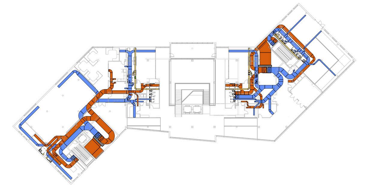
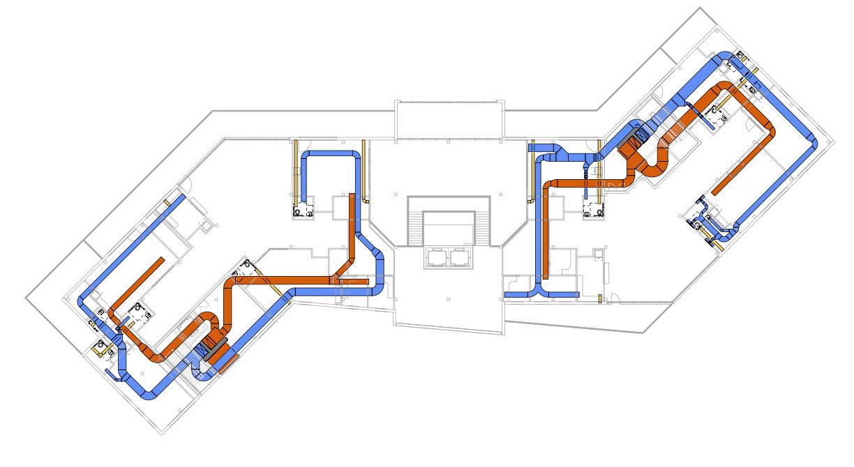
ENVIRONMENTAL SYSTEMS

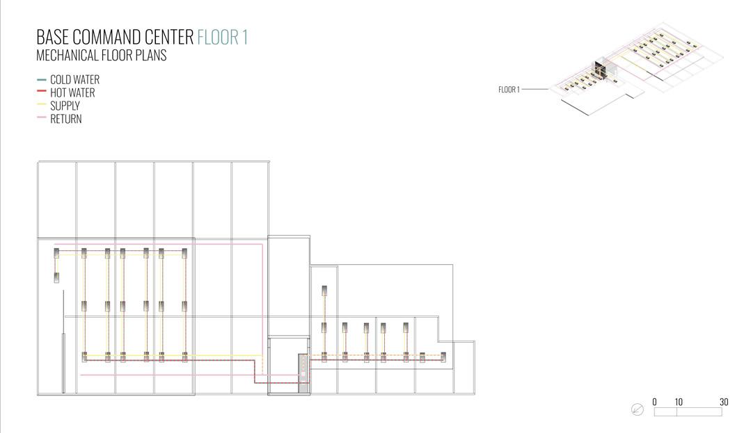
MECHANICAL PLAN FLOOR 1
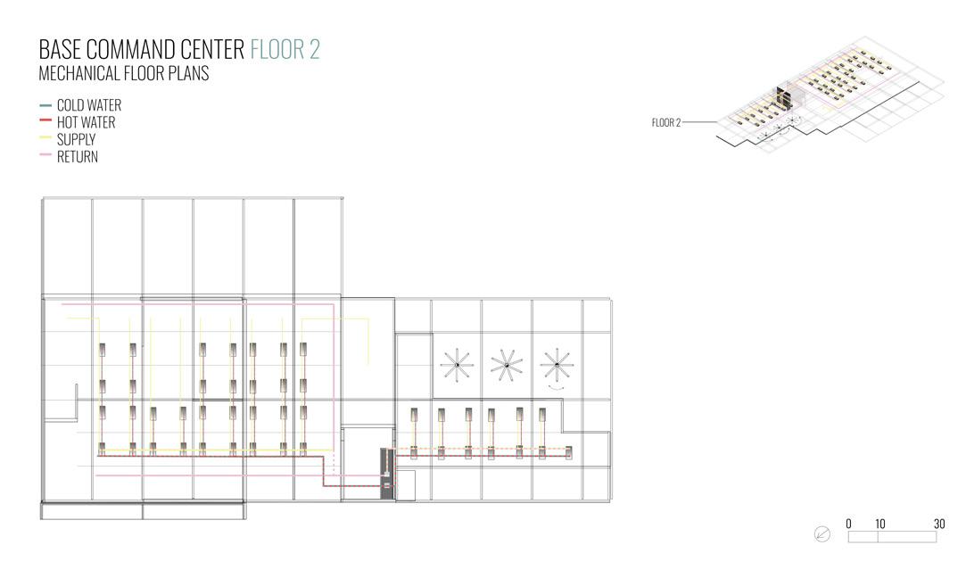
MECHANICAL PLAN FLOOR 2

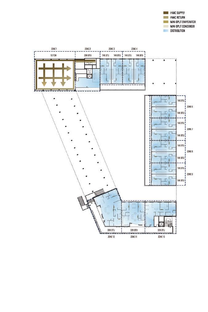
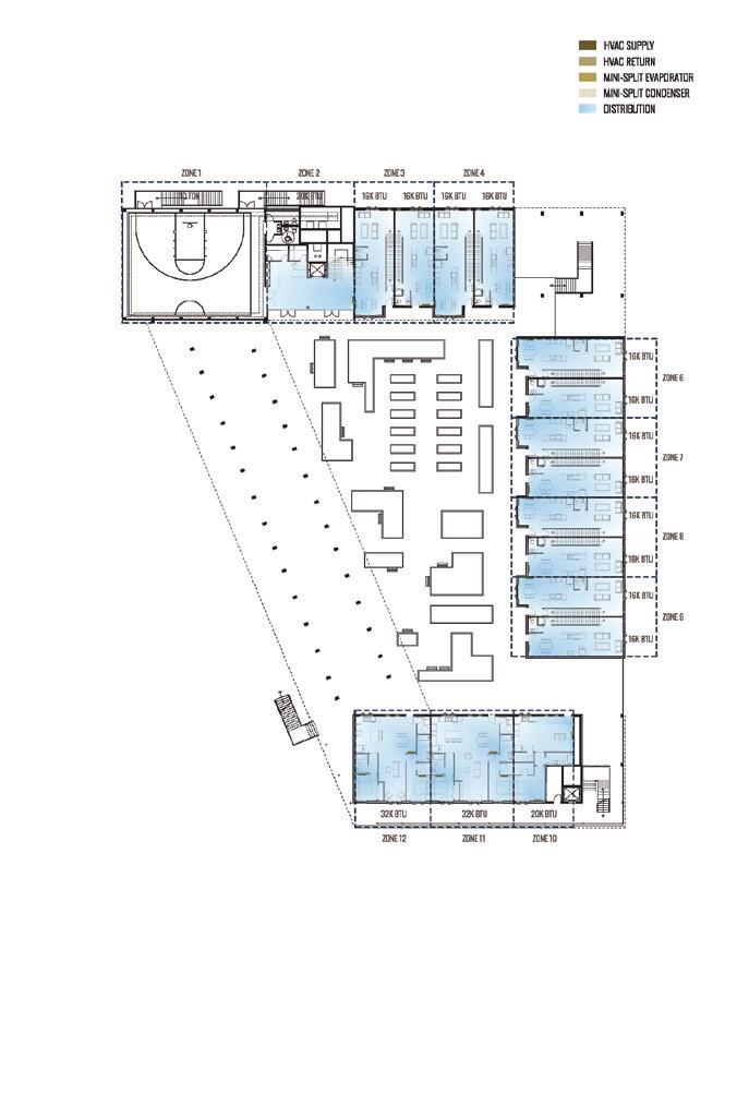
MECHANICAL PLAN FLOOR 3
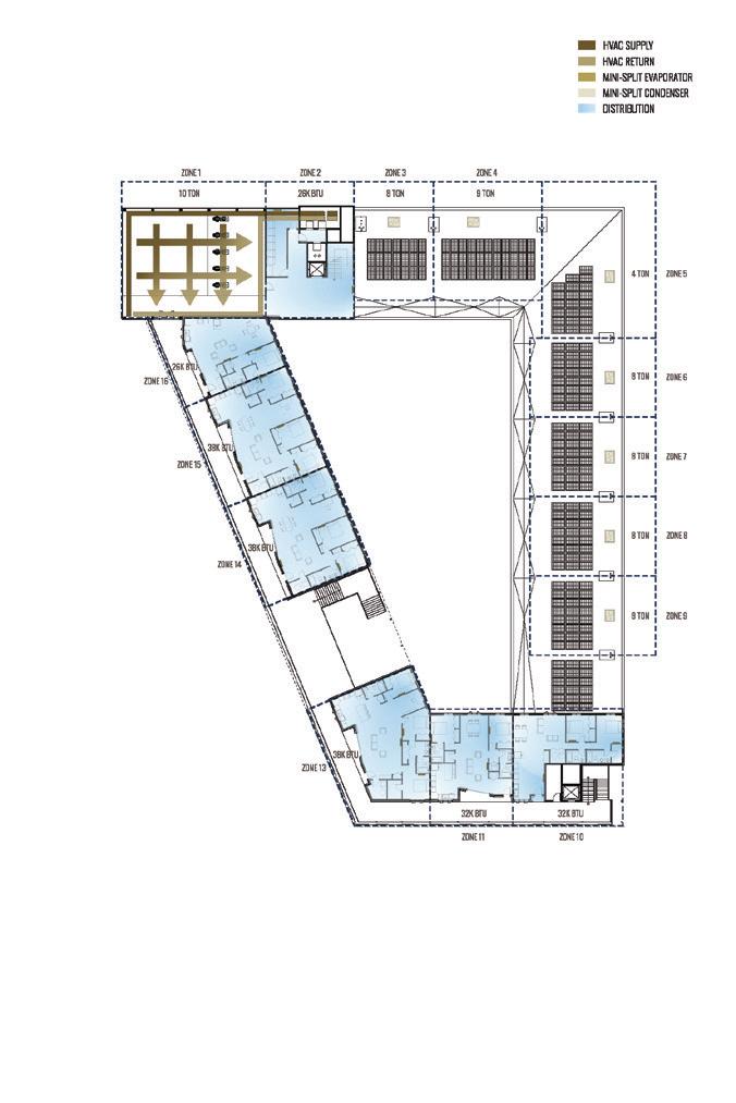
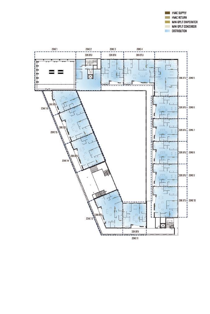
MECHANICAL PLAN FLOOR 4
MECHANICAL PLAN ROOF
278
MULTIFAMILY HOUSING | COURTNEY WOLFF + GEOFFREY POWELL + ZACHARY STUEMER
INTEGRATED SYSTEMS
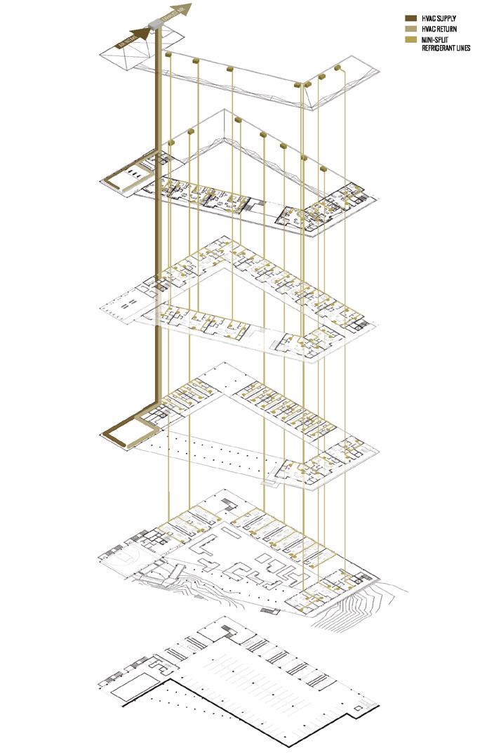
SYSTEMS DIAGRAM HEATING + COOLING
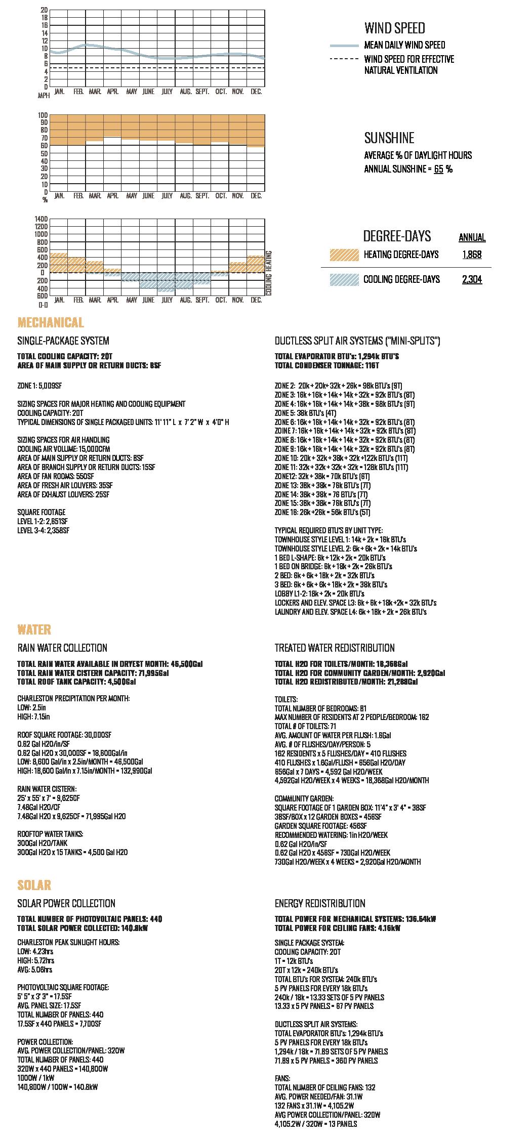
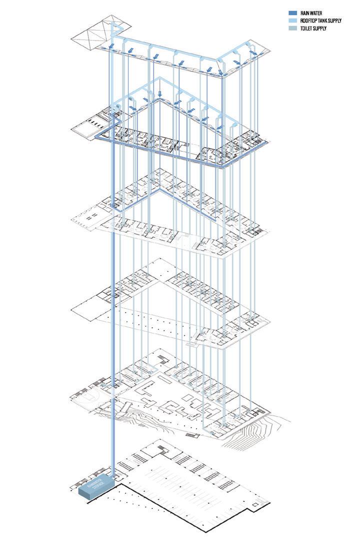
DIAGRAM SOLAR
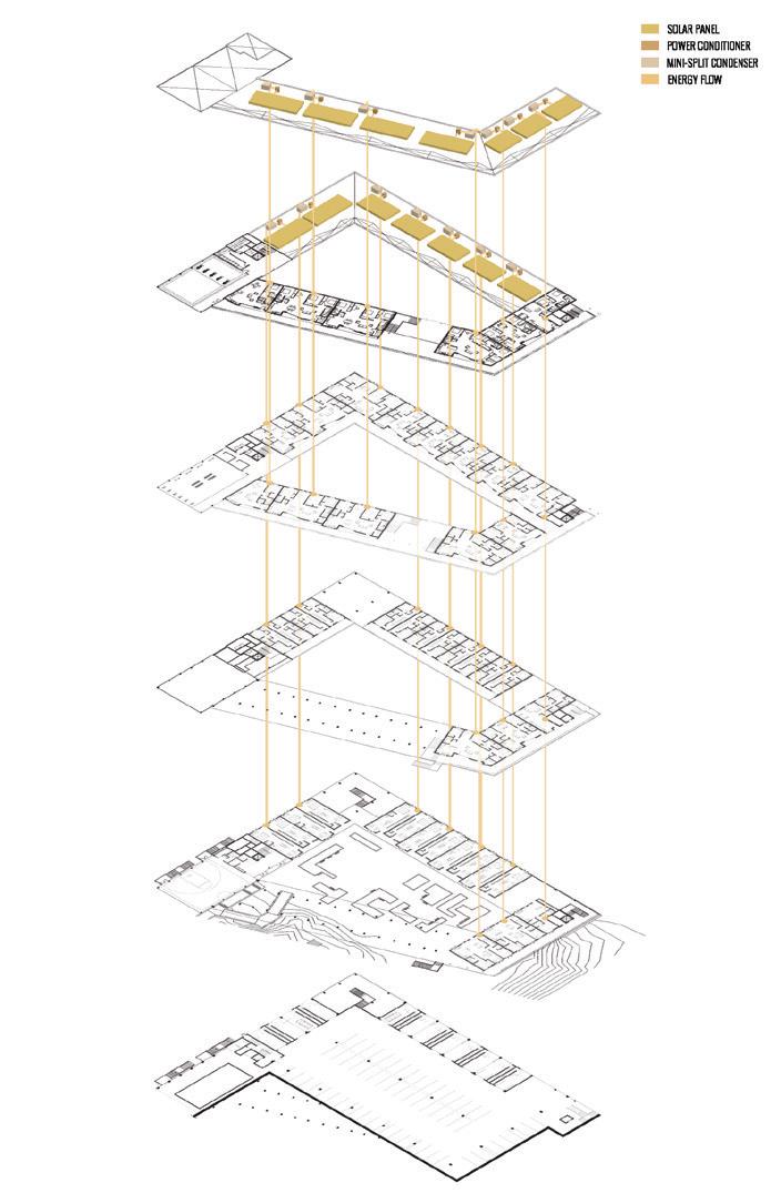
SYSTEMS
279 SUPERTEAM 4
280 MULTIFAMILY HOUSING | COURTNEY WOLFF + GEOFFREY
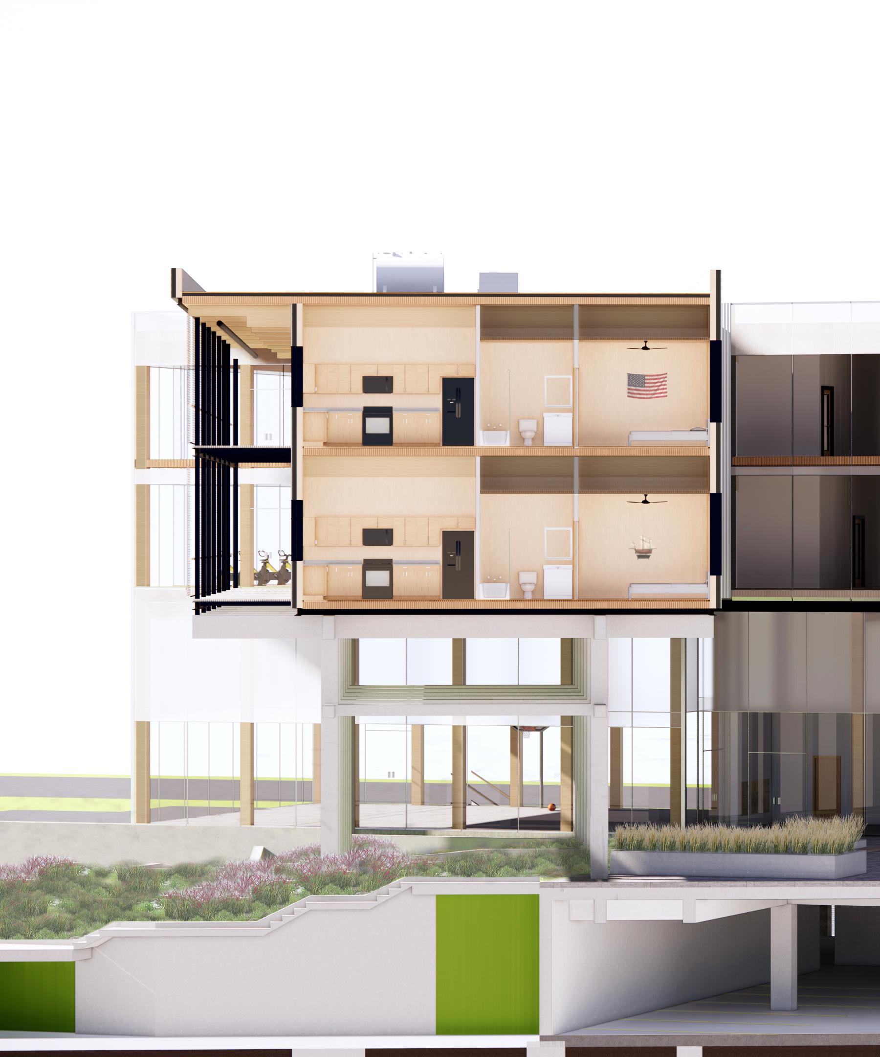
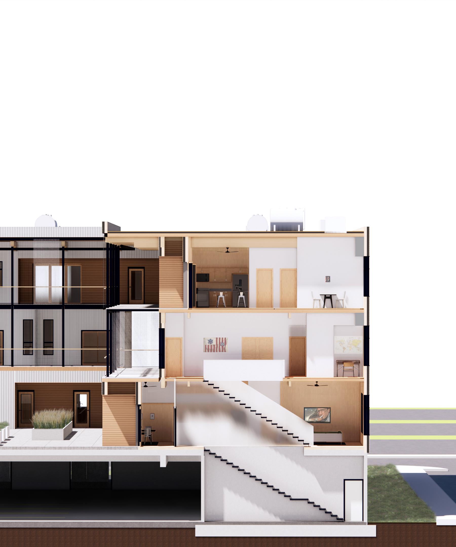
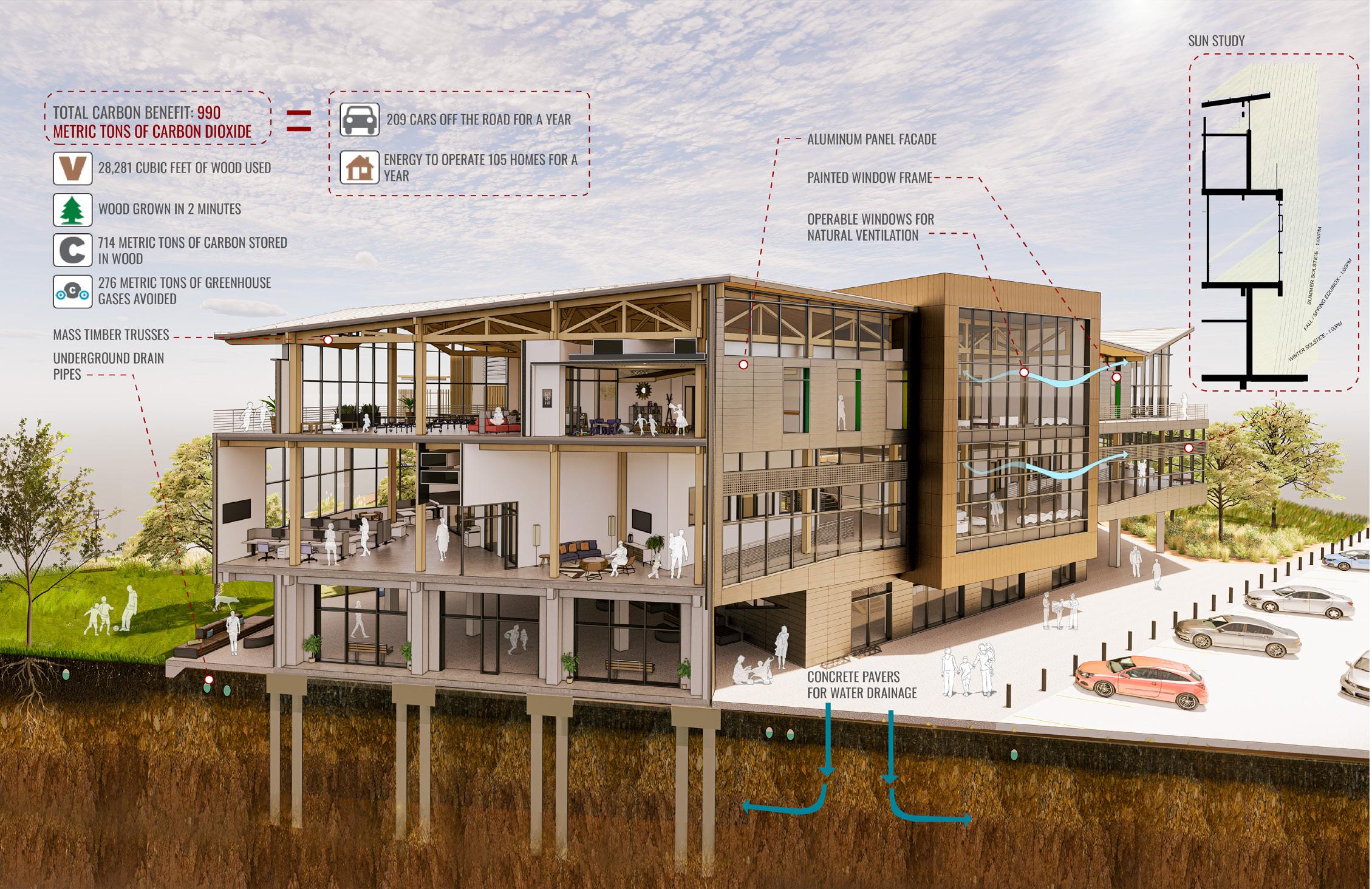
+ ZACHARY STUEMER BASE FLOOD ELEVATION - 15’ LEVEL 1 - 18’ LEVEL 2 - 30’ LEVEL 3 - 42’ LEVEL 4 - 55’ ROOF - 68’ FILL FROM OTHER LOCATIONS ON SITE FULL SHADE LINE DURING OVERHEATING PERIOD WINTERSUN SUMMER SUN RENDERED SECTION PERSPECTIVES
POWELL
281 SUPERTEAM 4
FULL SHADE LINE DURING OVERHEATING PERIOD WINTERSUN SUMMER SUN
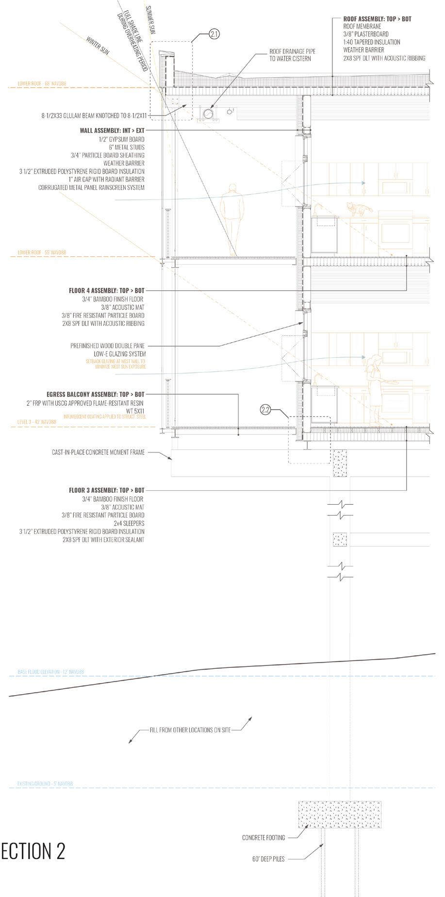
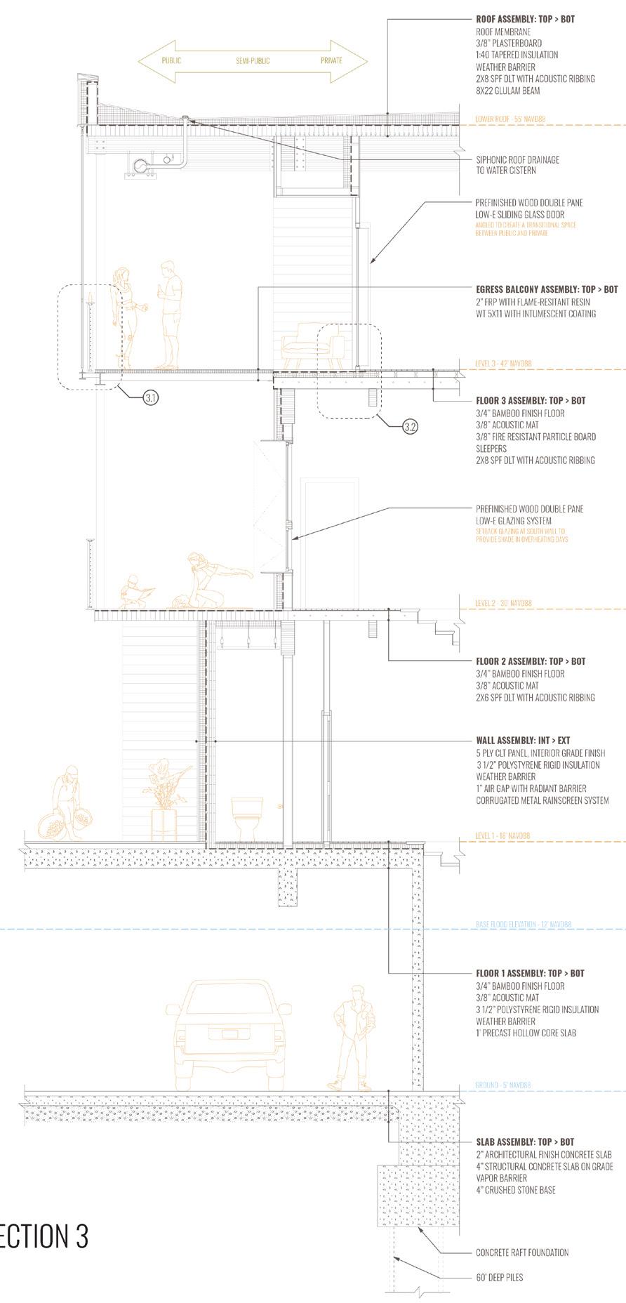
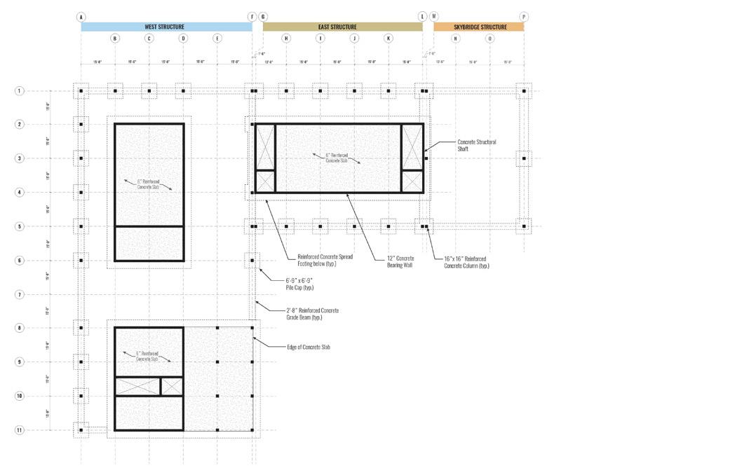
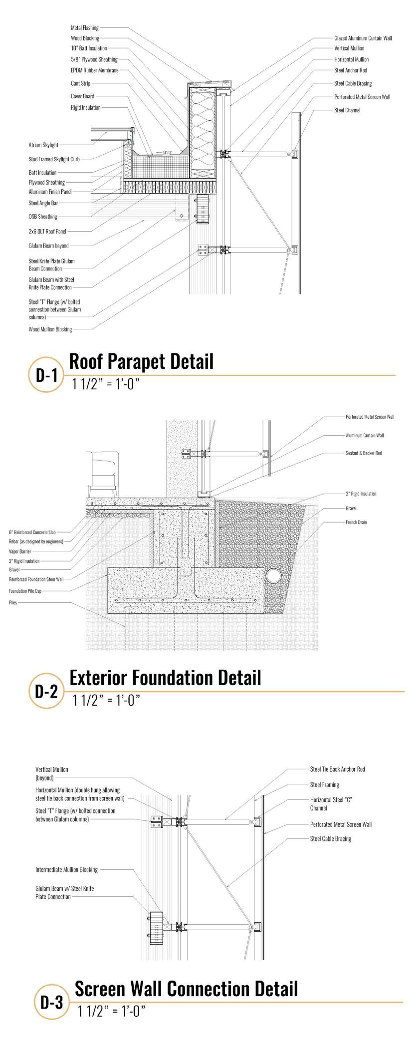
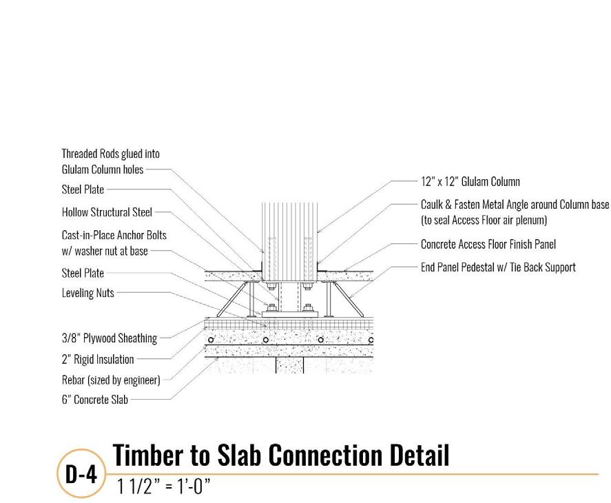
282 BUILDING ENVELOPE 1.2 1.1 PERFORMS WELL IN SEISMIC ZONES WRB IS TAPED AND SEALED AT JOINTS AND TRANSITIONS VENTILATED AND DRAINED 1” CAVITY METAL FURRING KNAPP CONNECTOR STAINLESS STEEL GROMMET FASTENER CROSS-CAVITY FLASHING FLASHING MEMBRANE OVERLAPPING HEAD FLASHING 2” CONCRETE TOPPING REINFORCED WITH STEEL FABRIC OVER PRECAST UNITS EXPOSED CONCRETE SLAB UNDERSIDE ANGLE BRACKETS VAPOR PERMEABLE WEATHER RESISTANT BARRIER SUSPENDED CEILING HANGERS SEALANT AND BACKER ROD FURRING BRACKETS SEALANT AND BACKER ROD CORRUGATED PANEL 1.2 1.1 PERFORMS WELL IN SEISMIC ZONES WRB IS TAPED AND SEALED AT JOINTS AND TRANSITIONS VENTILATED AND DRAINED 1” CAVITY METAL FURRING KNAPP CONNECTOR STAINLESS STEEL GROMMET FASTENER CROSS-CAVITY FLASHING FLASHING MEMBRANE OVERLAPPING HEAD FLASHING 2” CONCRETE TOPPING REINFORCED WITH STEEL FABRIC OVER PRECAST UNITS EXPOSED CONCRETE SLAB UNDERSIDE ANGLE BRACKETS VAPOR PERMEABLE WEATHER RESISTANT BARRIER SUSPENDED CEILING HANGERS SEALANT AND BACKER ROD FURRING BRACKETS SEALANT AND BACKER ROD CORRUGATED PANEL SECTION DETAILS BASE FLOOD ELEVATION 12’ NAVD88 FIRST FLOOR 18’ NAVD88 SECOND FLOOR 30’ NAVD88 THIRD FLOOR 42’ NAVD88 FOURTH FLOOR 55’ NAVD88 GROUND FLOOR 5’ NAVD88 1.1 1.2 SCREEN ALLOWS FOR VENTILATION IN PARKING GARAGE AS WELL AS WATER FLOW DURING FLOODING EVENTS FLUSH GLAZING AT NORTH WALL TO MAXIMIZE NORTH SKY EXPOSURE PREFINISHED WOOD DOUBLE PANE LOW-E GLAZING SYSTEM MINI-SPLIT REFRIGERANT LINES DROP-DOWN CEILING METAL SCREEN STOREFRONT 1:40 TAPERED INSULATION 2X8 SPF DLT WITH ACOUSTIC RIBBING 8X22 GLULAM BEAM ROOF MEMBRANE WEATHER BARRIER 3/8” PLASTERBOARD ROOF ASSEMBLY: TOP > BOT 5 PLY CLT PANEL, INTERIOR GRADE FINISH WEATHER BARRIER 3 1/2” EXTRUDED POLYSTYRENE RIGID BOARD INSULATION 1” AIR GAP WITH RADIANT BARRIER CORRUGATED METAL PANEL RAINSCREEN SYSTEM WALL ASSEMBLY: INT > EXT 3/4” BAMBOO FINISH FLOOR 3/8” ACOUSTIC MAT 3/8” FIRE RESISTANT PARTICLE BOARD SLEEPERS 2X8 SPF DLT WITH ACOUSTIC RIBBING FLOOR 3 ASSEMBLY: TOP > BOT 3/4” BAMBOO FINISH FLOOR 3/8” ACOUSTIC MAT 2X6 SPF DLT WITH ACOUSTIC RIBBING FLOOR 2 ASSEMBLY: TOP > BOT 3/4” BAMBOO FINISH FLOOR 3/8” ACOUSTIC MAT 3 1/2” EXTRUDED POLYSTYRENE RIGID BOARD INSULATION WEATHER BARRIER 1’ PRECAST HOLLOW CORE SLAB FLOOR 1 ASSEMBLY: TOP > BOT 2” ARCHITECTURAL FINISH CONCRETE SLAB 4” STRUCTURAL CONCRETE SLAB ON GRADE VAPOR BARRIER 4” CRUSHED STONE BASE SLAB ASSEMBLY: TOP > BOT CONCRETE FOOTING PERFORATED DRAINAGE PIPE 60’ DEEP PILES SECTION 1 WALL SECTION 1 SECTION DETAILS: 1.1 , 1.2 MULTIFAMILY HOUSING | COURTNEY WOLFF + GEOFFREY POWELL + ZACHARY STUEMER WALL SECTION 2
283 SUPERTEAM 4 SECTION DETAILS 2.2 2.1 STAINLESS STEEL GROMMET FASTENER CORRUGATED PANEL MOVEABLE MESH SCREEN SYSTEM FLASHING OVER L 8X6X8X0.500 FLASHING OVER L 8X6X8X0.500 PRESSURE-TREATED WOOD SILL PLATE 2X8 SPF DLT FLOOR PANEL ATTACHED W8X24 WITH THROUGH BOLTS W8X24 ATTACHED TO CONCRETE MOMENT FRAME (BEYOND) WITH ANCHOR BOLTS 2X8 SPF DLT FLOOR PANEL SEALED 2X8 SPF DLT WITH EXTERIOR SEALANT HSS 5X5X3/8 COLUMN ATTACHED TO GLULAM BEAM WITH KNIFE PLATE CONNECTION STEEL CABLE CROSS-BRACING Z-BRACKET VENTILATED AND DRAINED 1” CAVITY FURRING CHANNEL Z-BRACKET 2” FRP WITH USCG APPROVED FLAME-RESISTANT RESIN VENTILATED AND DRAINED 1” CAVITY INTUMESCENT COATING APPLIED TO STRUCT. STEEL INTUMESCENT COATING APPLIED TO STRUCT. STEEL FURRING CHANNEL FLASHING CAP WRB IS TAPED AND SEALED AT JOINTS AND TRANSITIONS VAPOR PERMEABLE WEATHER RESISTANT BARRIER SECTION DETAILS 1/2” ROUND HOLLOW STEEL TUBING 2” FRP W/USCG APPROVED FLAME RESISTANT RESIN 6” SEALED WOOD COCKTAIL RAILING 2” X 1” HOLLOW STEEL MOVABLE MESH SCREEN SYSTEM 4” HOLLLOW STEEL BALUSTER W 4 X 13 STEEL WITH INTUMESCENT COATING W 12 X 45 STEEL WITH INTUMESCENT COATING 200 X 200 TEE STEEL 140 X 140 TEE STEEL LOW PROFILE SLIDING DOOR ROLLER 9’ X 7’ SLIDING 3 PANEL DOOR DOUBLE PANE LOW-E GLAZING 2” X 2” RIGID CONNECTOR ANGLE 5” X 11” GLULAM BEAM 2” X 4” SLEEPER VAPOR PERMEABLE WEATHER RESISTANT BARRIER 1/8” CONCRETE TOPPER SLAB 3.2 3.1 SECTION DETAILS: 2.1 , 2.2 WALL SECTION 3 SECTION DETAILS: 3.1 , 3.2
284
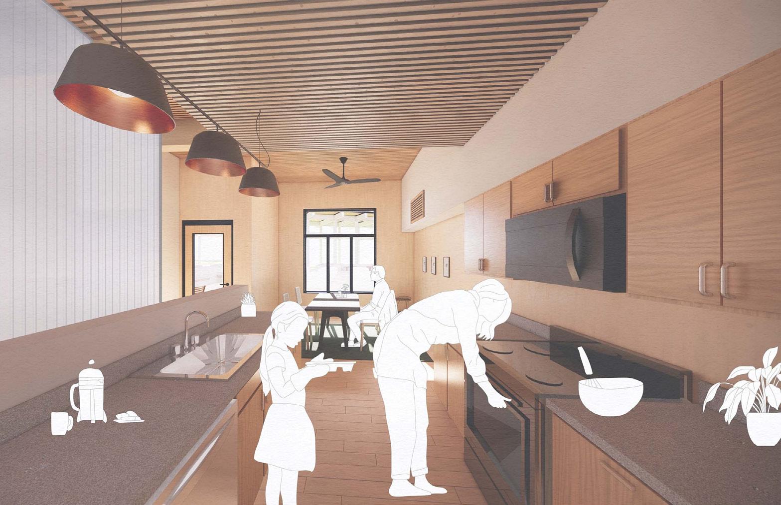
INTERIOR DWELLING KITCHEN + DINING
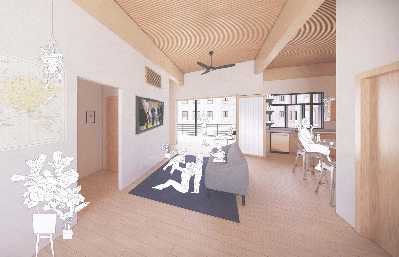
INTERIOR DWELLING LIVING ROOM
MULTIFAMILY HOUSING | COURTNEY WOLFF + GEOFFREY POWELL + ZACHARY STUEMER
285 SUPERTEAM 4
EXTERIOR VIEW: PORCH AT NIGHTTIME
EXTERIOR VIEW: COURTYARD SPACE
286
MULTIFAMILY HOUSING | COURTNEY WOLFF + GEOFFREY POWELL + ZACHARY STUEMER
287 SUPERTEAM 4
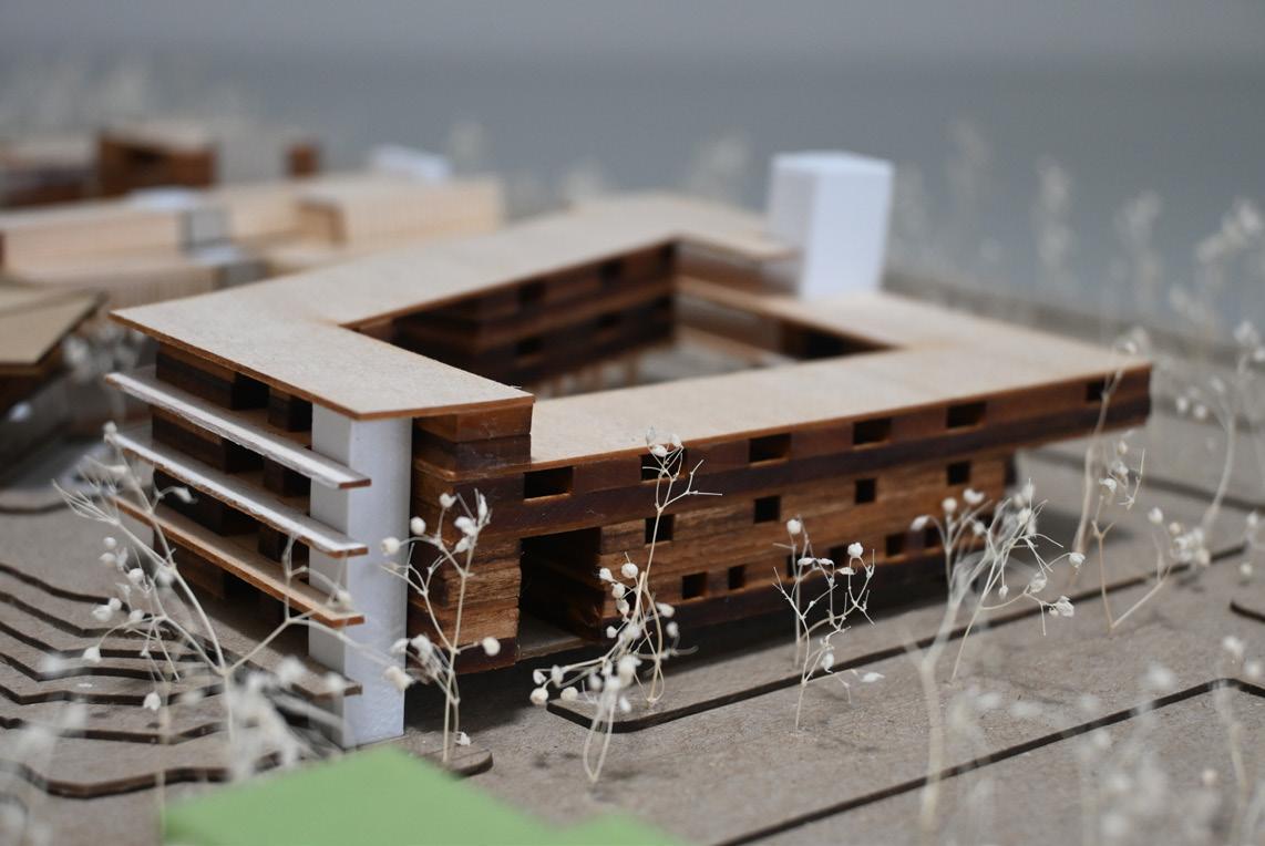
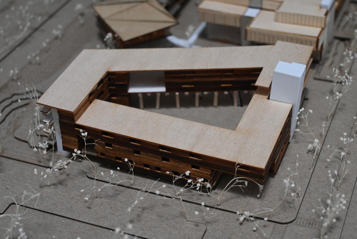
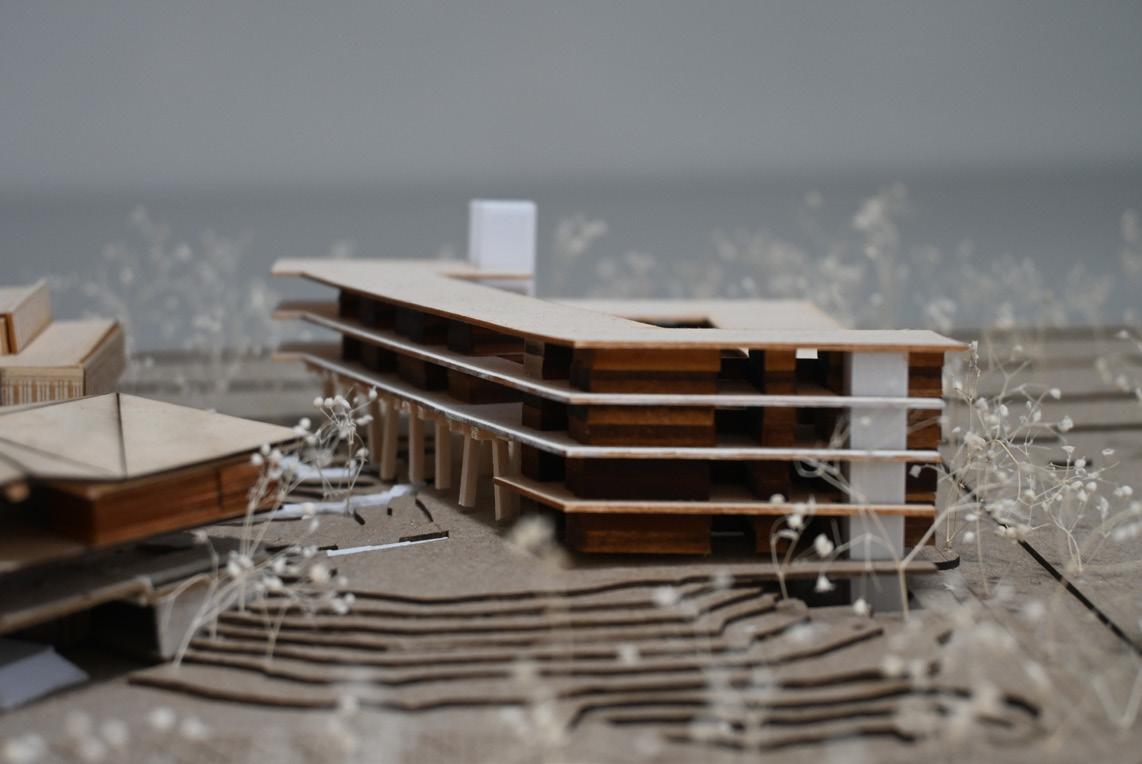
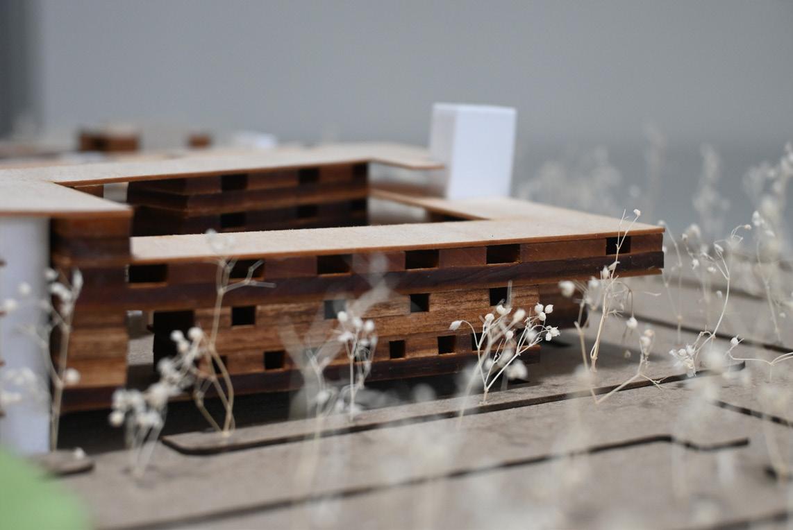
PHYSICAL MODEL
CHILD DEVELOPMENT CENTER
FOR SUPERTEAM 4 SUB-MASTERPLAN
Premise Context
DANIEL MECCA LAUREN PRAEUNER


Occupant Interaction + Circulation Fostering Creativity
When designing any building, circulation is one of the first things we look at as an architect. How are people moving through the site? How are people using the site? How can we bring people to the site? Most importantly, how do people move through the building? While this is true for any building, it is especially true when considering a child’s safety and playful nature. So, in the case of a child development center, how does a child walk through a building.
The way a child experiences the world is much different than how an adult does, and spaces designed for small children should consider a child’s scale. By viewing space through the eyes of a child, we may aim to create intriguing environments that promote learning and creativity. Additionally, I would like to study how children’s spaces merge with adult spaces and how the architecture of a building can reflect the scale of activity.
Question
How can the building provide spatiality that gives freedom for autonomy, self-expression, and the discovery of creative identity in children?
How can design slow someone down and allow them to be fully aware of what they are doing now?
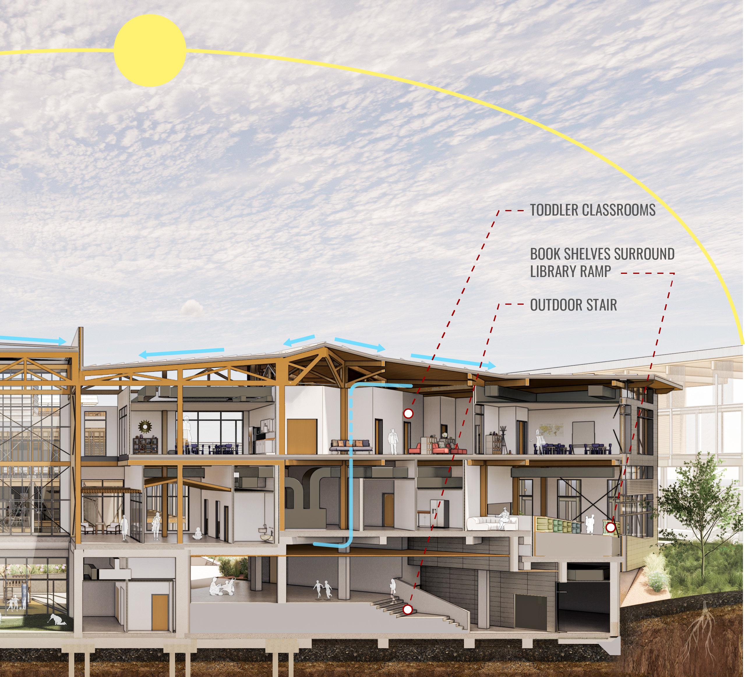
Designed to be a secure yet accessible building in the heart of our Charleston Coast Guard base, the Child Development Center began by designing a mixed circulation scheme. The design required programs including childcare, pre-k care, toddler care, a public library, and a public maker space, making the separation of access one of the most critical aspects.
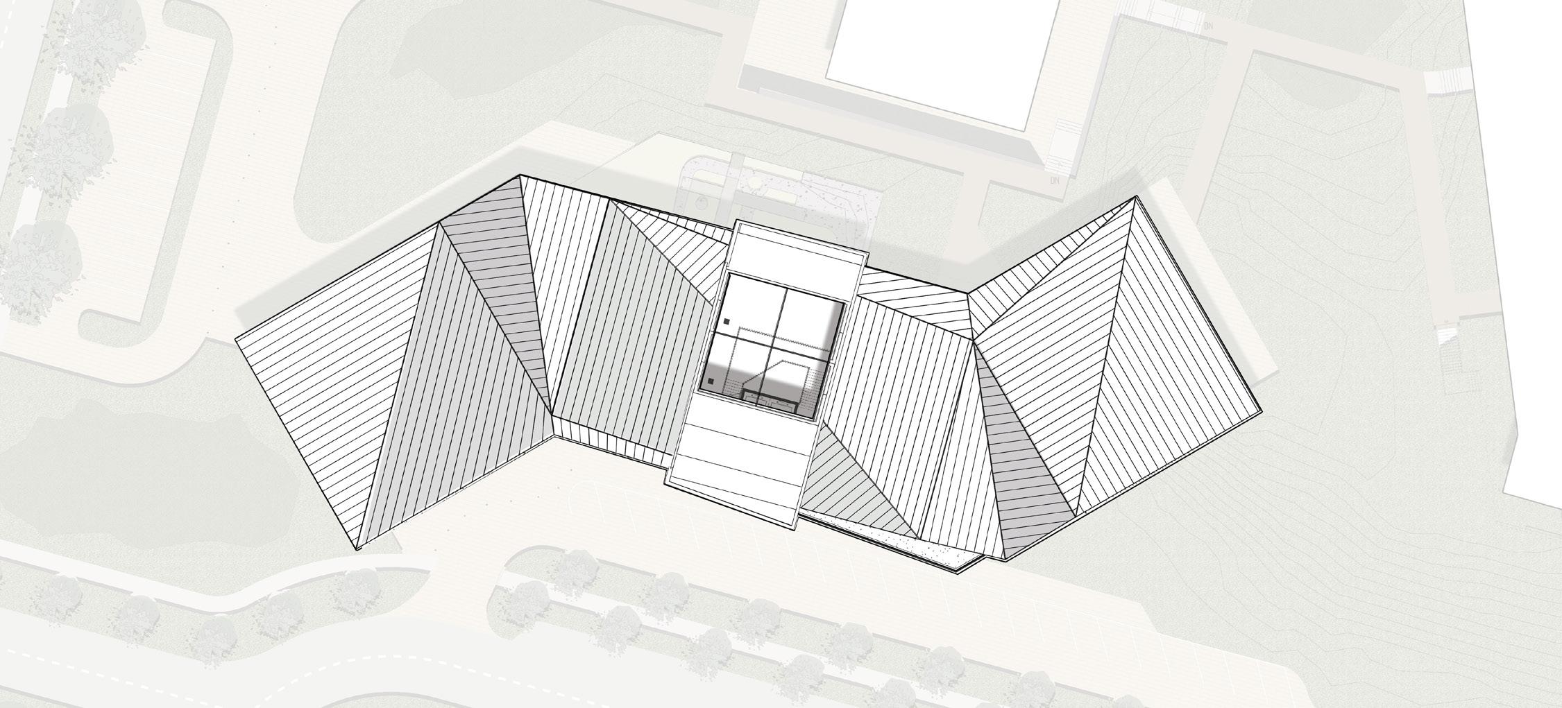
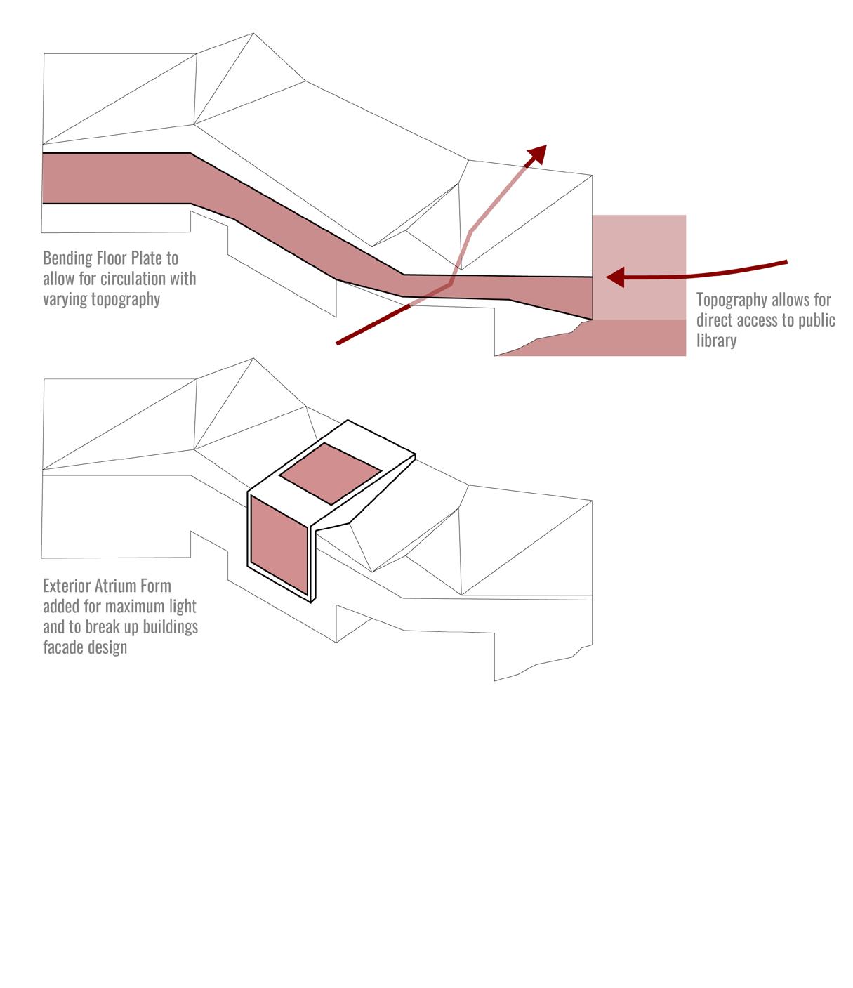
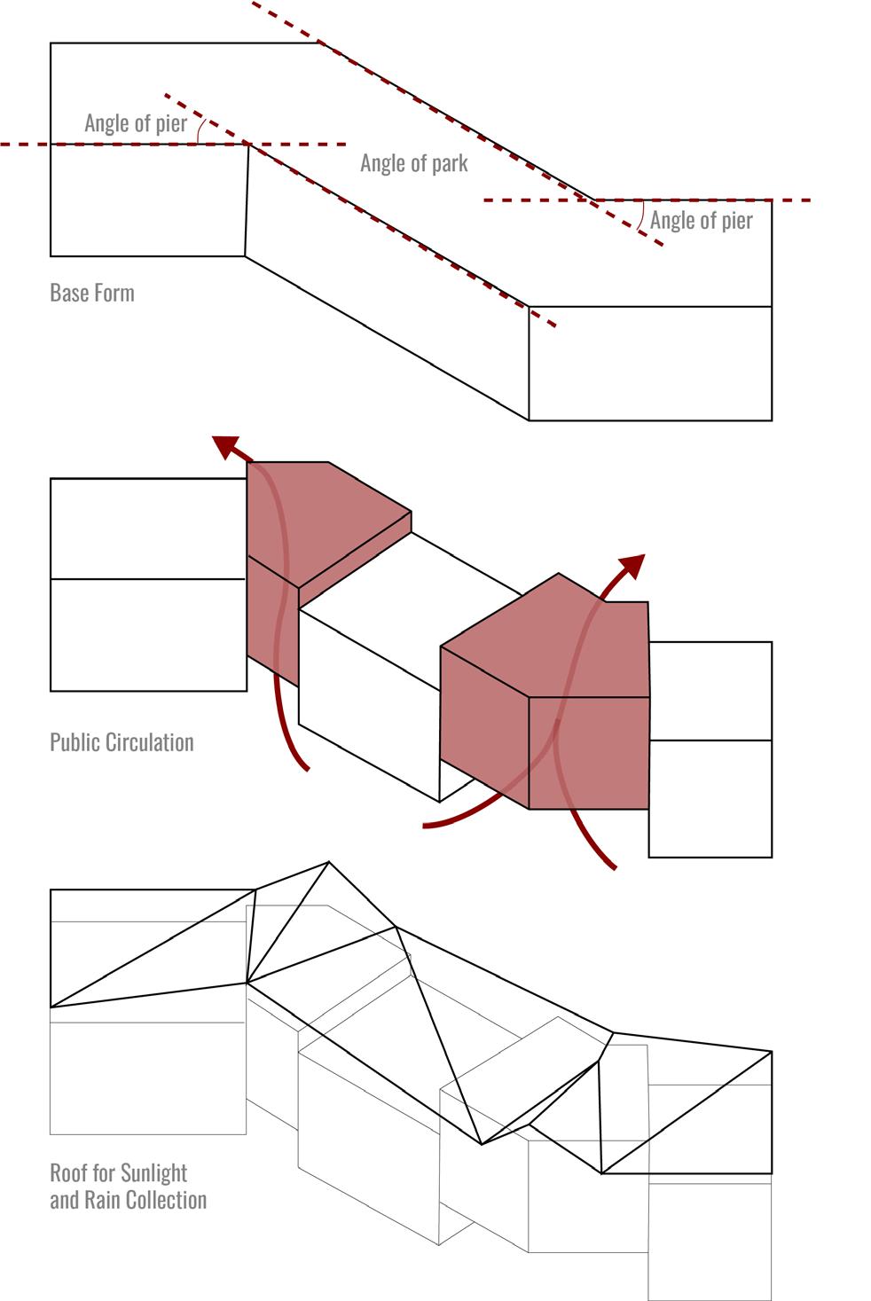
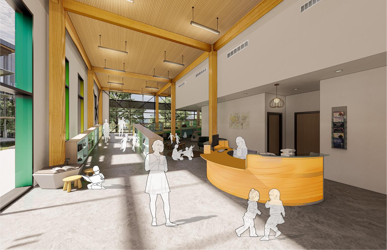
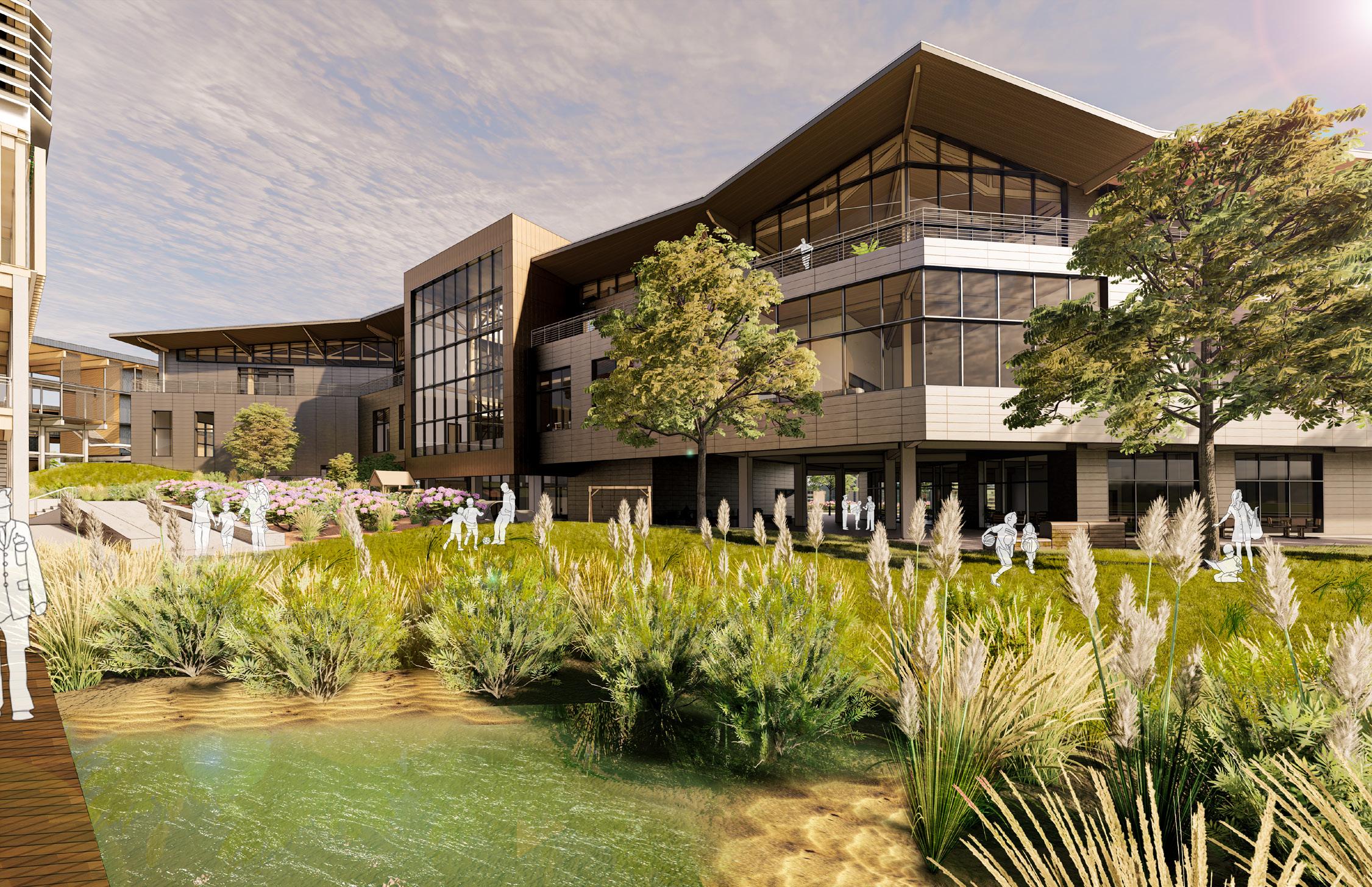
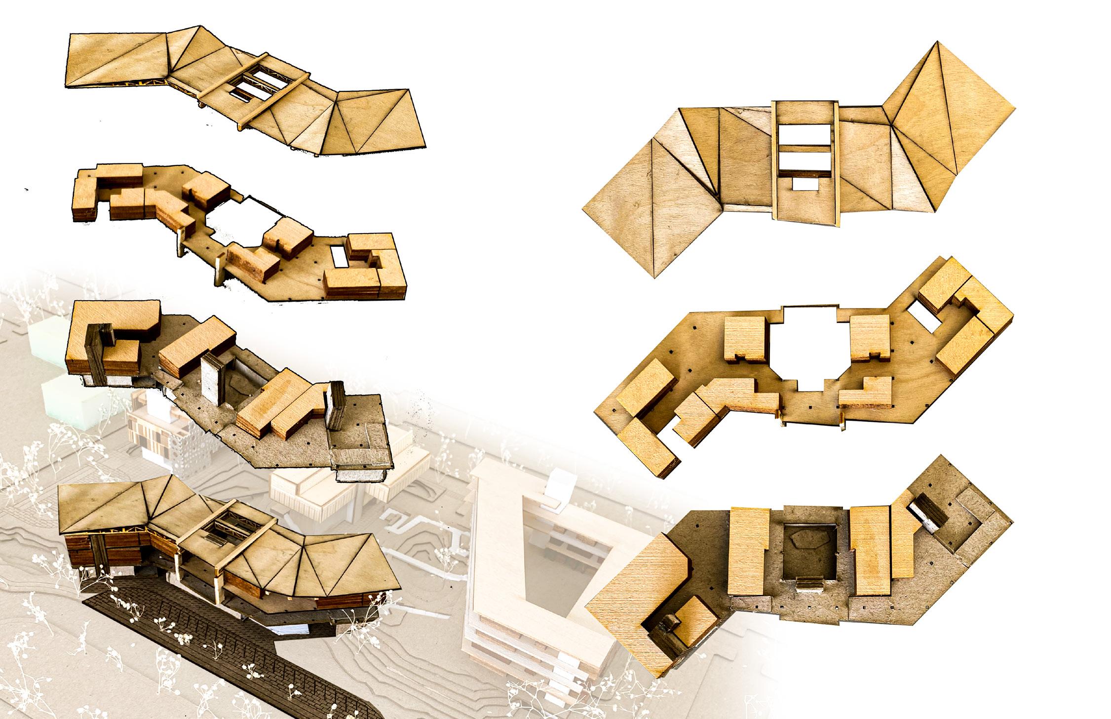
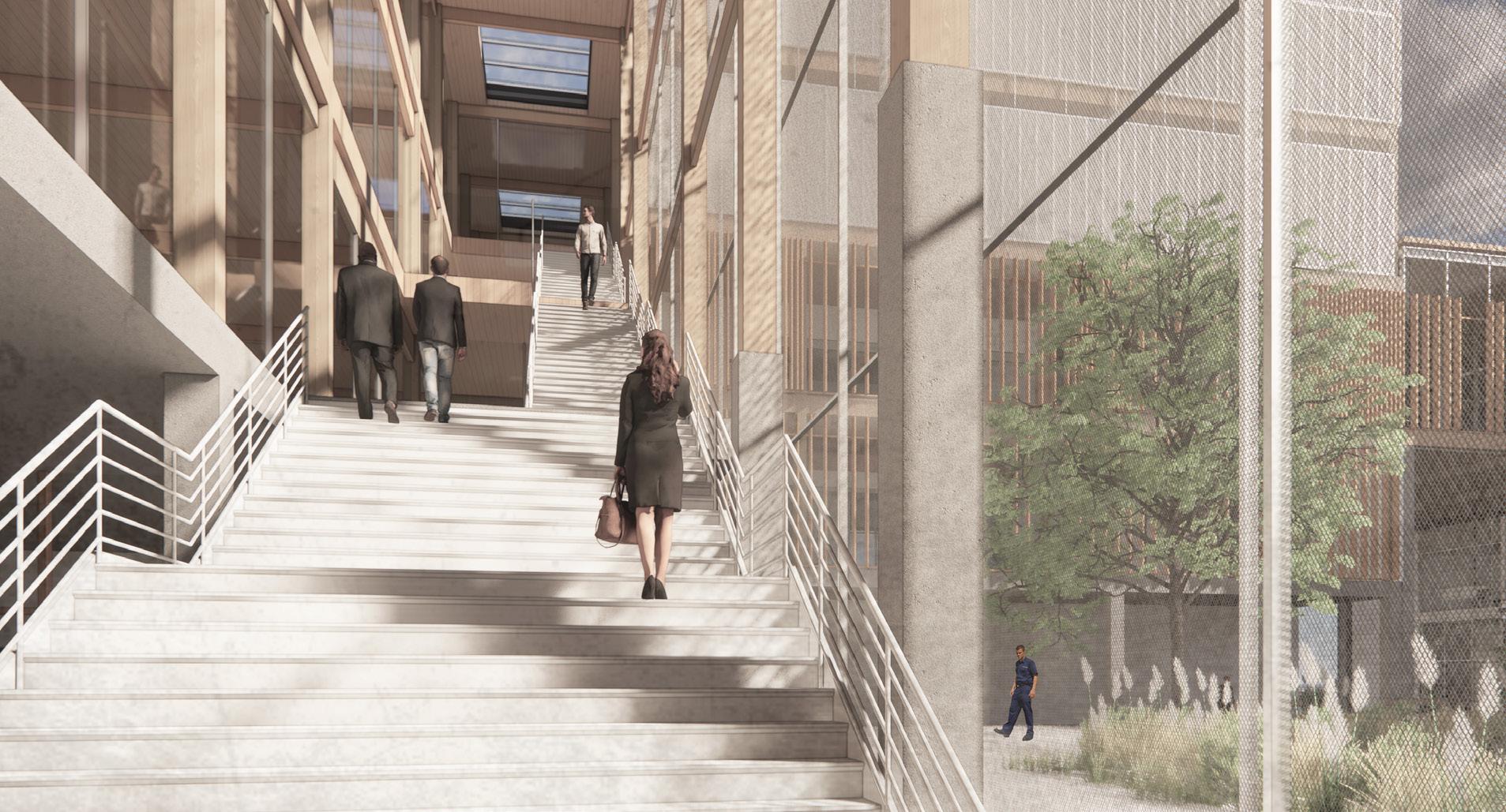
This Child Development Center integrates ease of circulation and the separation of programs with the idea of scale and childinfluenced design. These two premises offer an extensive range of programs (both childcare and public) and highlight the importance of undulating scale for the well-being of children. The shape of this building came from the need for a permeable base that allowed public circulation routes through the building without it going through any child programs to keep it secure. The fortyfive-degree angles that house the public programs speak to the angle of the pier. The roof was decided upon to not only control water and allow sunlight into the spaces but also create a fun ceiling condition in a space where kids will be playing all day long in the form of an underwater atmosphere. The site’s topography slopes up to our building for ease of public access to our library on the second floor and as an emergency exit for small children that keep them from needing to be corralled down flights of stairs.
The mass timer aspect of the project also plays an important role. As seen through the structural drawings and diagrams, the beams, columns, and cross-laminated panels all play a role that communicates with the other systems in the building and creates a playful and lighthearted atmosphere for the children using the program.
288
CHILD DEVELOPMENT CENTER |
DANIEL MECCA + LAUREN PRAEUNER
CHILD DEVELOPMENT CENTER LOCATION ON SITE
289 SUPERTEAM 4
OUTDOOR RECREATION
INDOOR RECREATION 3250 SF
MULTIPURPOSE PUBLIC USE 2500 SF
WASTE CENTER 260 SF
RISER ROOM 200 SF
2ND FLOOR PLAN
GREENHOUSE 560 SF
INFANT ROOM 725 SF
GROUND FLOOR PLAN O
OPEN OFFICE 1050 SF
SHOP OFFICE 175 SF
LAB/ TECH. SPACE 350 SF
LEVEL 1 FLOOR PLAN
CHILD DEVELOPMENT CENTER | DANIEL MECCA + LAUREN PRAEUNER
WATER COLLECTION AREA 1100 SF
BUILDING STORAGE 260 SF
GALLERY 675 SF COMMUNITY PLAZA
INFANT ROOM 550 SF
COMMUNITY LIBRARY 2725 SF
MOTHERS’ ROOM 200 SF
MECHANICAL 1200 SF
PARENTS LOUNGE 780 SF
MECHANICAL 625 SF
290
RECEPTION/ SECURITY 245 SF E O E W
MAKERS SPACE 2530 SF
GROUND LEVEL FLOOR PLAN
PRE-K ROOM 660 SF
MULTIPURPOSE SPACE 1375 SF
KITCHEN 200 SF
PRE-K ROOM 640 SF
PRE-K ROOM 590 SF
MECHANICAL 385 SF
PRE-K ROOM 650 SF
PRE-K ROOM 625 SF
MECHANICAL 625 SF
KITCHEN 180 SF
PATIO
MULTIPURPOSE SPACE 1375 SF
TODDLER ROOM 500 SF
PATIO TODDLER ROOM 600 SF
TODDLER ROOM 575 SF
291 SUPERTEAM 4
O EN O E OW
3RD FLOOR PLAN
ROOF PLAN
LEVEL 3 FLOOR PLAN
DESIGN STRATEGIES DIAGRAMS
292
CHILD DEVELOPMENT
CENTER | DANIEL MECCA + LAUREN PRAEUNER
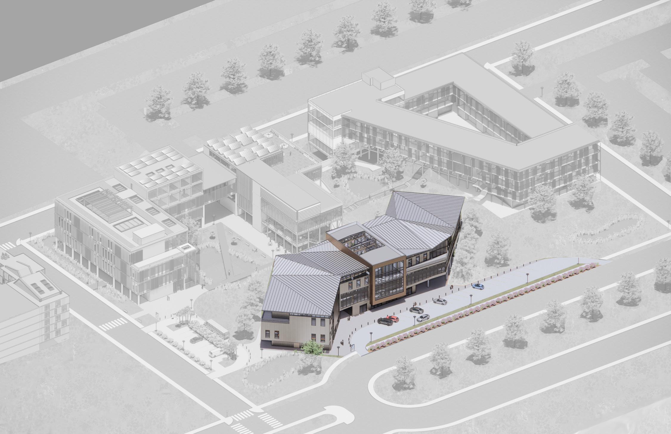
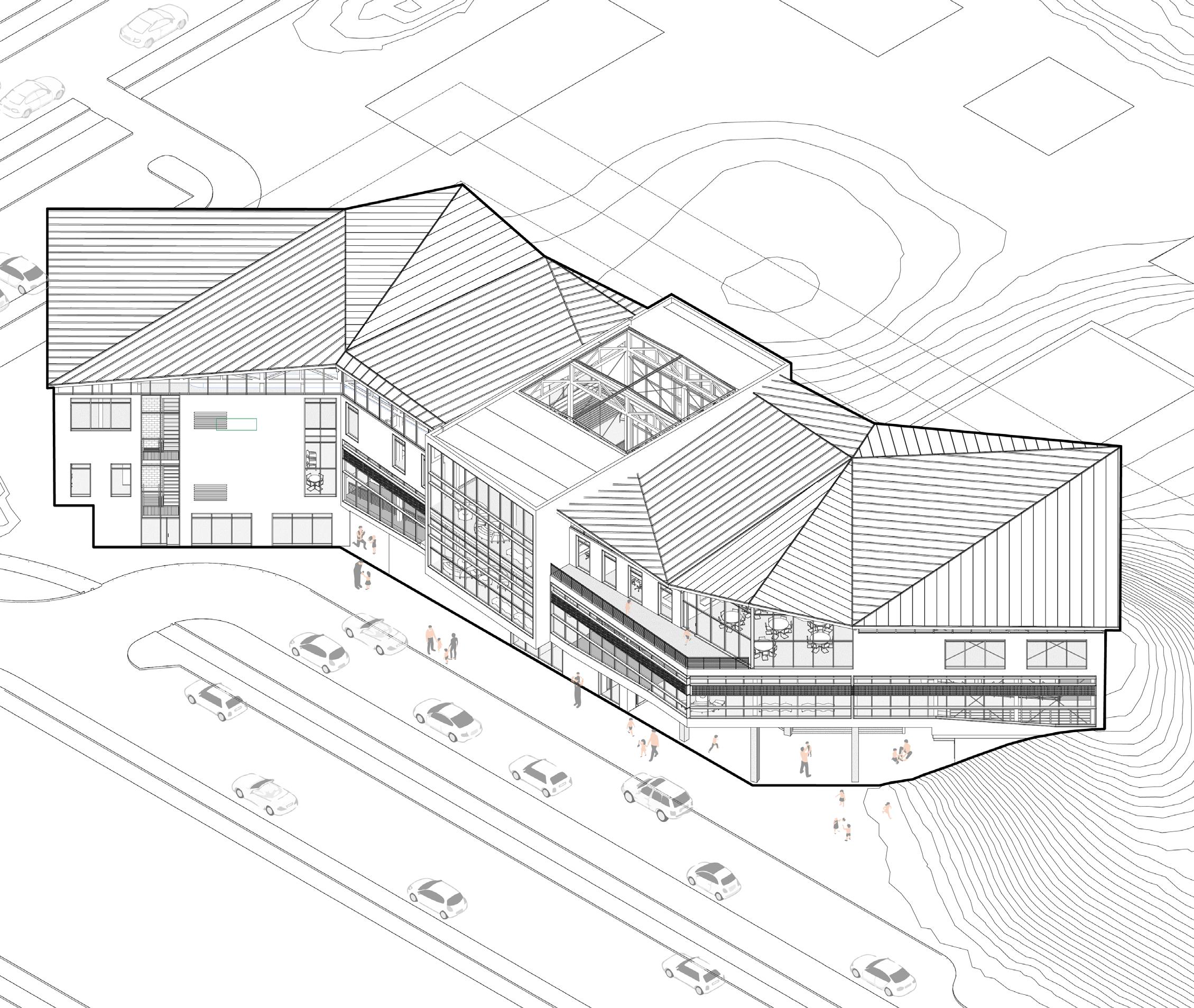
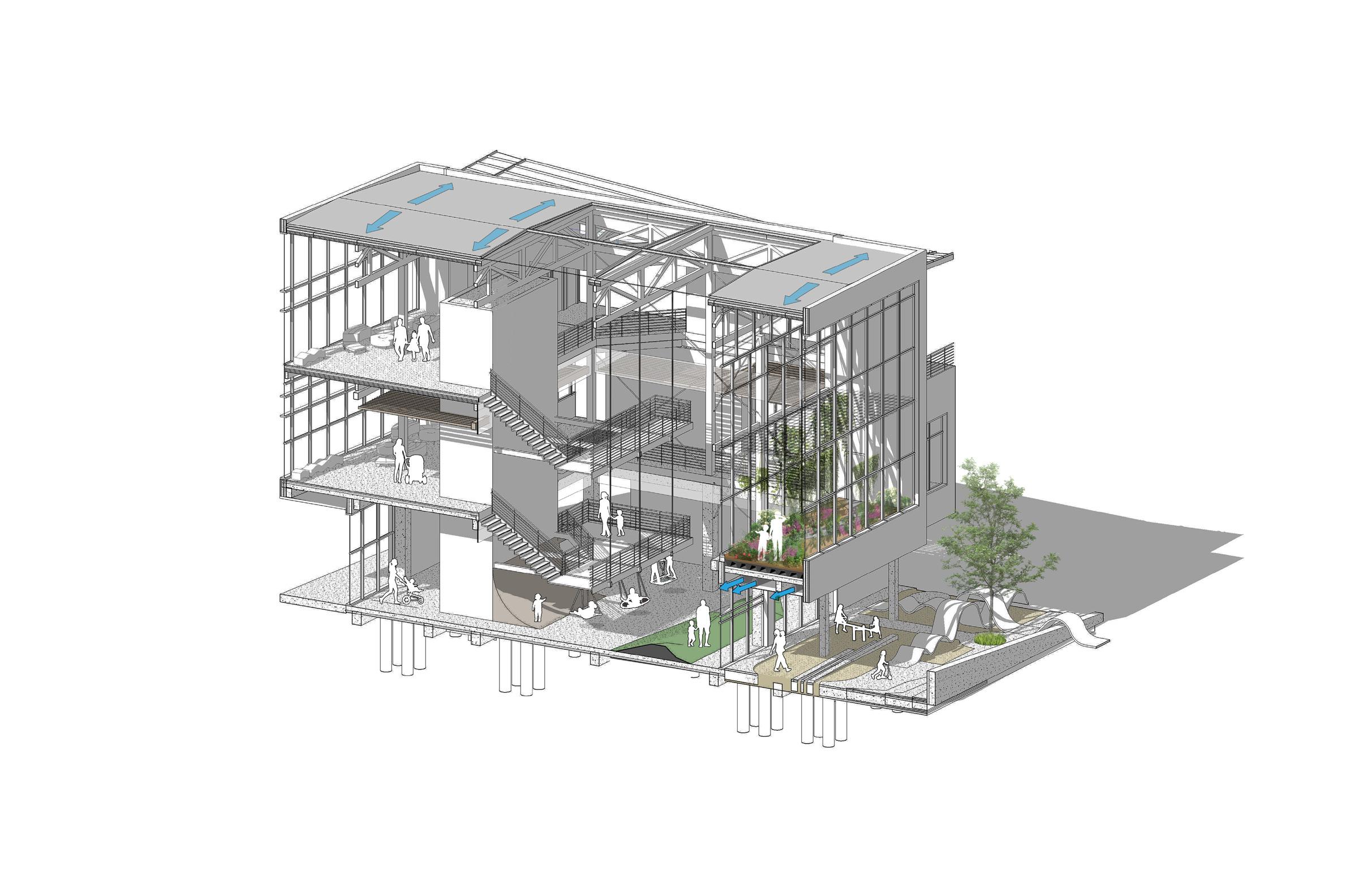
BUILDING AXONOMETRIC PERSPECTIVE DRAWING
293 SUPERTEAM 4
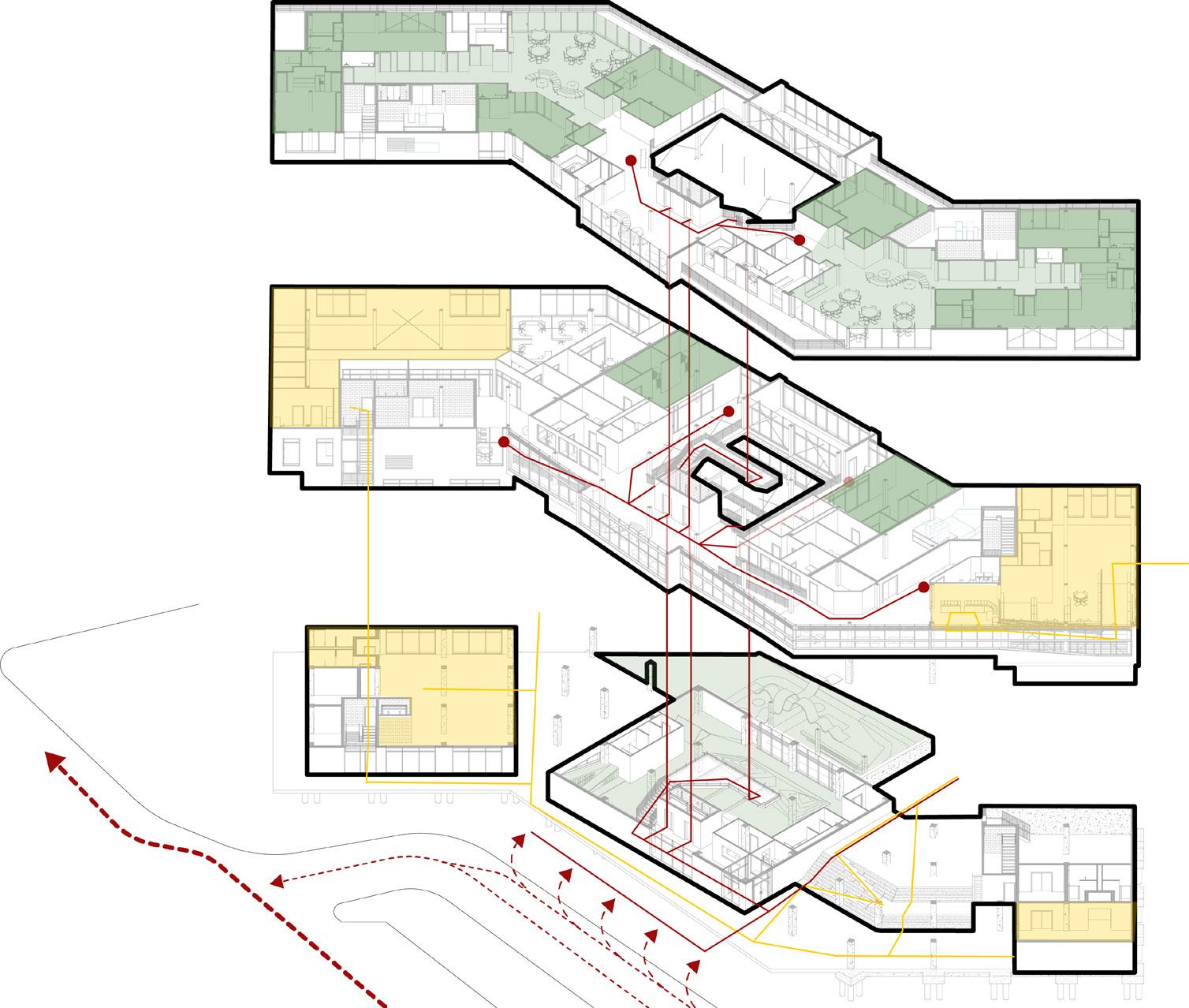
CIRCULATION AND SCALE
294
CIRCULATION + SPATIAL SCALE DIAGRAM CHILD DEVELOPMENT
CENTER | DANIEL MECCA + LAUREN PRAEUNER
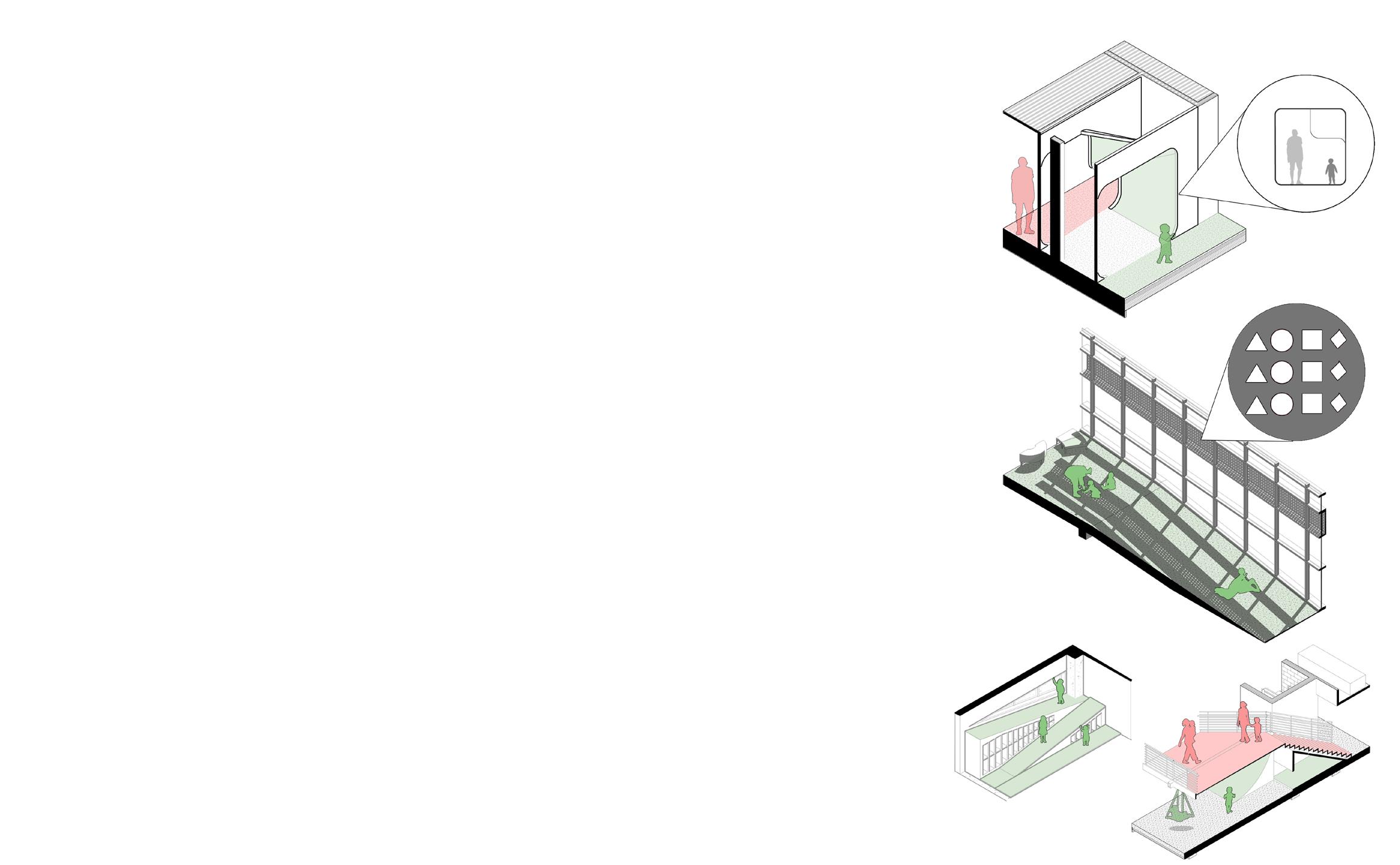
ATRIUM
ROOF DRAINAGE
DRAINS THROUGH THE PARAPET TO THE DRAINS CONNECTED TO COLLECTION
STAIRS
STAIRS ARE HUNG FROM TRUSS BY TENSION RODS
SMOKE PROTECTION
A B B C
GLASS PARTITIONS WORK WITH EXHAUST ON EACH LEVEL AROUND THE ATRIUM TO KEEP SMOKE FROM ENTERING ATRIUM
INDOOR PLAY AREA
CIRCULATION POINTS BREAK THIS LARGE SPACE INTO 3 DIFFERENT SCALE HEIGHTS
INDOOR GARDEN
2-STORY SPACE ALLOW FOR GROUNDGROWN PLANTS AND HANGING PLANTS. DRAINAGE THROUGH FLOOR BACK TO WATER RETENTION.
OUTDOOR PLAYGROUND
SANDPIT WITH EQUIPMENT SCALED FOR ALL AGE GROUPS
295 SUPERTEAM 4
C D D E E
A
F F ATRIUM DIAGRAM
296 RETA NING WALL CONCRETE PILES CAST N PLACE CONCRETE SLAB GRADE BEAMS CONNECTING P LES CMU EGRESS STA R 20 X 20 CONCRETE COLUMNS 18 X 12 CONCRETE BEAMS TENSION ROD CROSS BRACING 12 X 12 GLULAM COLUMN 5-PLY CLT FLOOR GLULAM TRUSSES 3 -PLY FOLDED CLT ROOF 6 X 12 GLULAM BEAM METAL END CAP 6 X 24 GLULAM BEAM 6 X 6 GLULAM BEAM 5 8 D A CARRAGE BOLT STEEL PLATE JACK -K FE CONNECTION STEEL PLATE ON GLULAM COLUMN GLULAM COLUMN GLULAM COLUMN STEEL PLATE W TH PIPE CONNECT ON P PE SL DES NTO P PE BELOW PRE -DR LLED HOLE N CLT GLULAM BEAM 5 8 D A CARRAGE BOLTS CONTINUOUS BEAM THROUGH NOTCHED COLUMN MITER CUT CLT PANELS PLATES ALL SEPARATE AND ARE PRE- NSTALLED N THE TRUSS AND ON COLUMNS BOLTED TOGETHER ON S TE STRUCTURAL AXON STRUCTURAL AXONOMETRIC DIAGRAM STRUCTURE CHILD DEVELOPMENT CENTER | DANIEL MECCA + LAUREN PRAEUNER
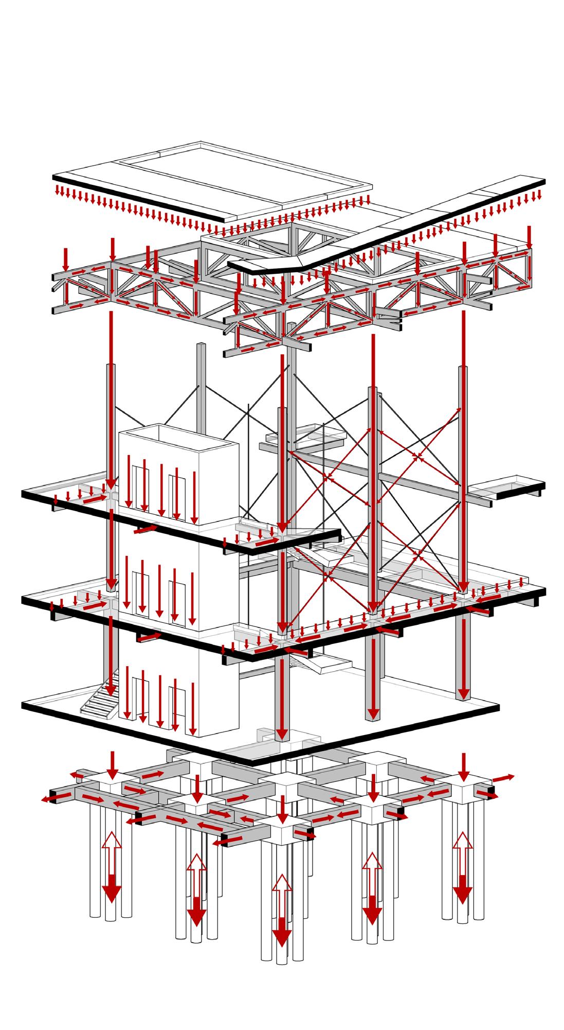
297 SUPERTEAM 4 1 A.1 A.2 A.3 8 10 11 12 13 15 16 17 C.3 B.3 B.1 C.4 U A CO UOU AMSP CO UOU AMSP TNUO EAMS N ONTN SBE AN N N SBE AN NTNU S E AN NTNU E AN TNU EA S N C UO AMS C UO AMS C O M CO OU AMSP TNUO EAMS N--------3 1 A.1 A.3 12 14 16 17 C.1 C.2 B.4 B.1 A.4 C.4 ON USB M P CON OU AMS N TO ROOF TRUSS HOLDING CO OU AMS N CON OU AMS N O OU AMS ON N USB M P ON USB M P CO UO EAM AN CO UO A S N C TN SB PA O M--20' 1/4"--6 5 A.2 A.3 10 11 14 15 C.1 C.2 B.2 B.3 B.4 A.4--12' 0" 1/16" 12'--A.2 A.3 12 13 C.1 C.2 C.3 B.3 B.1 A.4 C.4-------GRADE BEAMS PLACED UNDER EGRESS GRADE BEAMS PLACED UNDER EGRESS LEVEL 1 FRAMING PLAN LEVEL 2 FRAMING PLAN LEVEL 3 FRAMING PLAN LEVEL 4 FRAMING PLAN LOAD PATH DIAGRAM
298 CHILD DEVELOPMENT CENTER | DANIEL
+ LAUREN PRAEUNER
MECCA
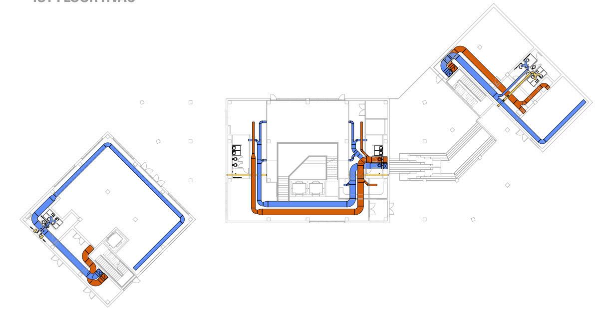
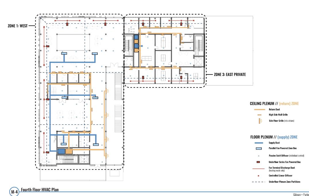
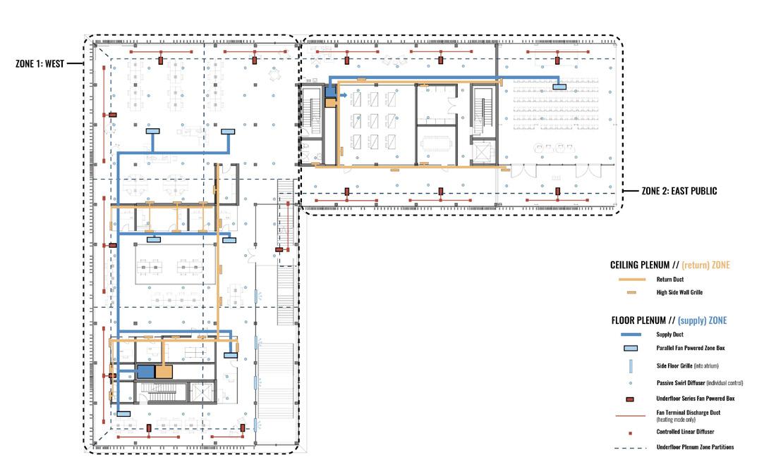
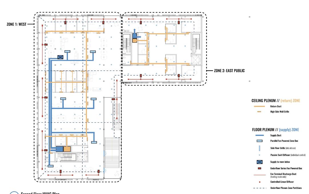
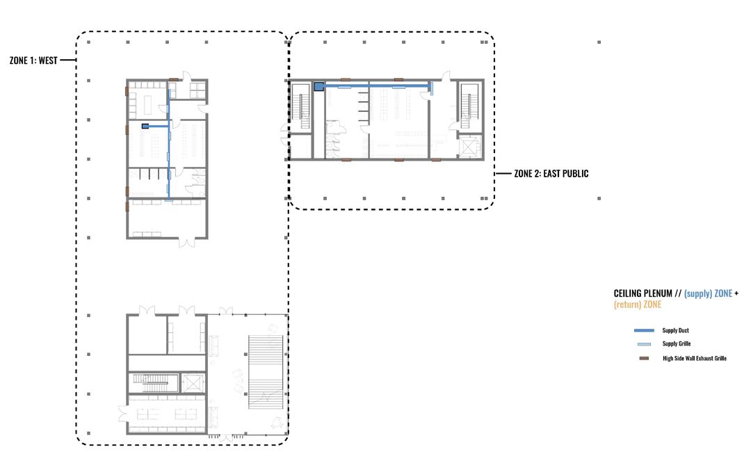
ENVIRONMENTAL SYSTEMS LEVEL 1 HVAC PLAN LEVEL 2 HVAC PLAN LEVEL 3 HVAC PLAN WATER COLLECTION DIAGRAM
299 SUPERTEAM 4 SECTION PERSPECTIVE
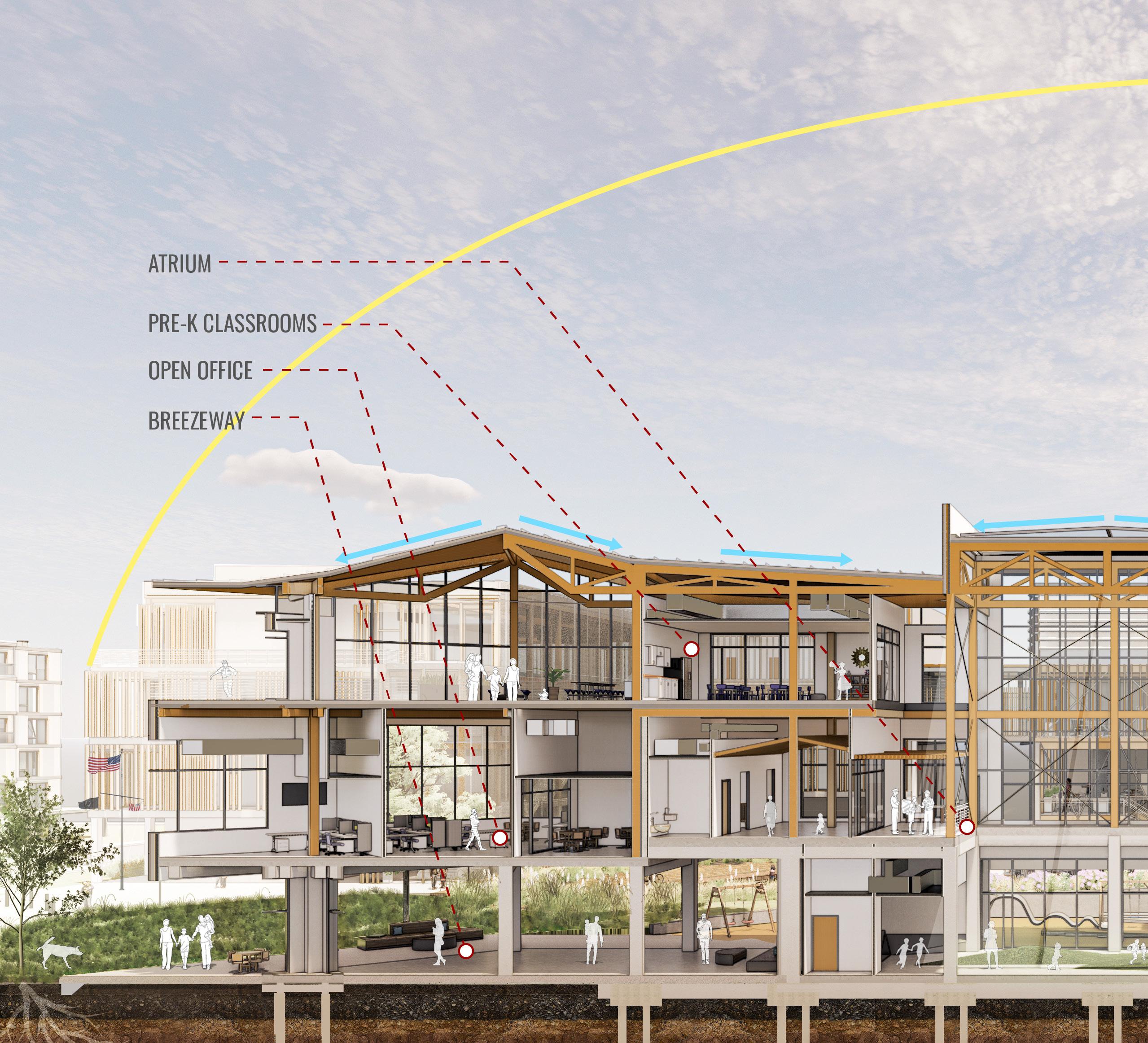
300 RENDERED SECTION PERSPECTIVE CHILD DEVELOPMENT CENTER
| DANIEL MECCA + LAUREN PRAEUNER
301 SUPERTEAM 4
302
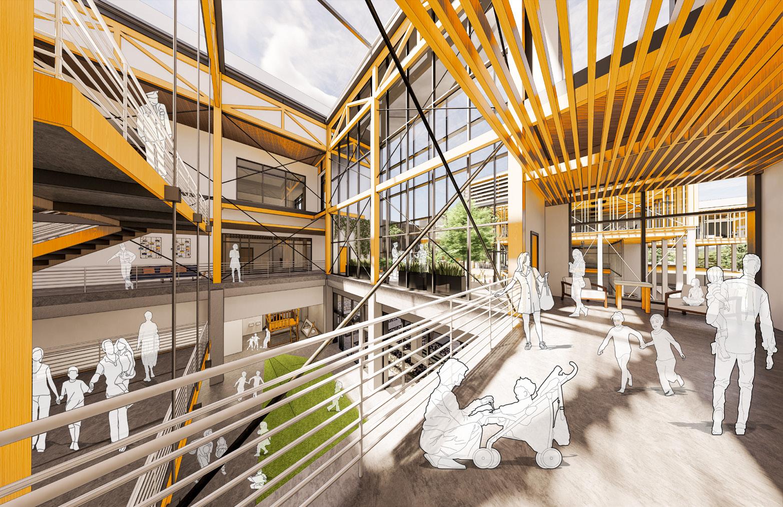
INTERIOR VIEW: ATRIUM
CHILD
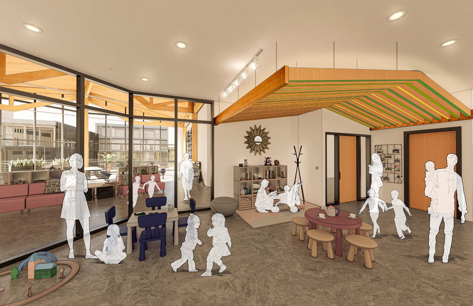
INTERIOR VIEW: CLASSROOM SPACE
DEVELOPMENT CENTER | DANIEL MECCA + LAUREN PRAEUNER
303 SUPERTEAM 4
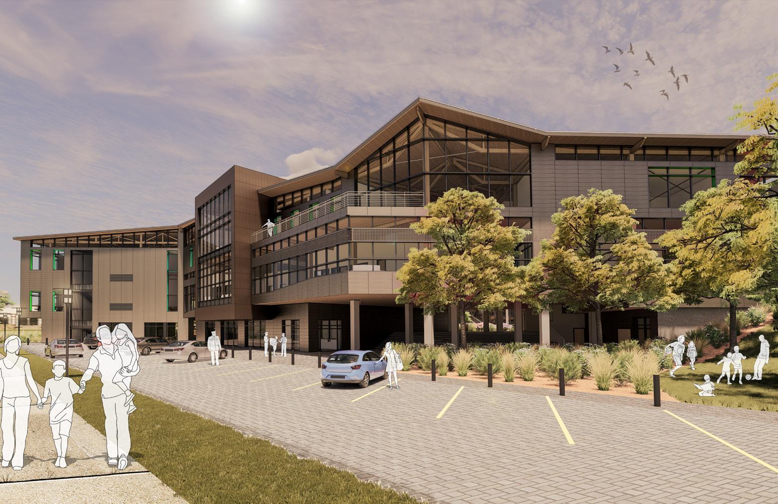
EXTERIOR VIEW: MAIN APPROACH FROM PARKING LOT
INTERIOR VIEW: LOBBY SPACE
304
CHILD DEVELOPMENT
EXTERIOR VIEW: SOUTHEAST CORNER
CENTER | DANIEL MECCA + LAUREN PRAEUNER
305 SUPERTEAM 4
PHYSICAL MODEL BREAKDOWN DIAGRAM
SECTOR COMMAND
FOR SUPERTEAM 4 SUB-MASTERPLAN
Premise
SYDNEY PARKER EMMA GIBSON
Structure + Space Environmental Responsiveness + Seamless Interior/Exterior
Context
In design, structural systems often feel more like a design constraint than a design opportunity. Though managed by two different design disciplines, the fusion of architectural and structural design in the conceptual and developmental phases has the potential to enrich the overall design rather than become a roadblock to the spaces we desire to create.
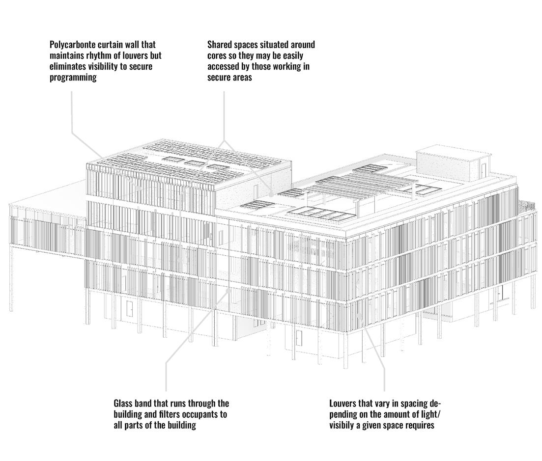
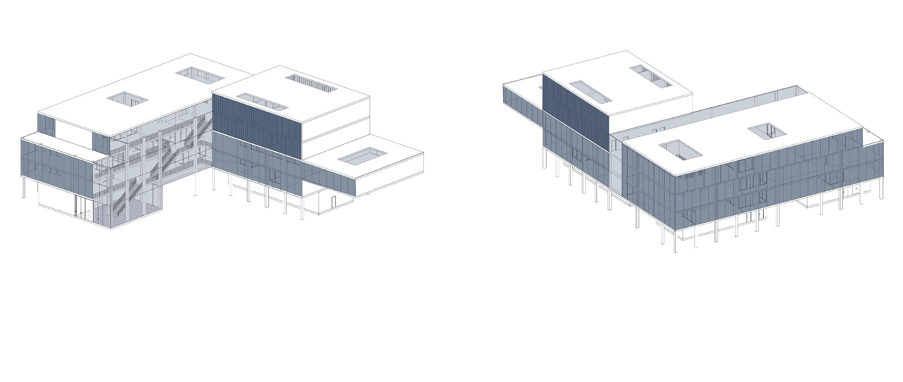
We were tasked with designing a building that welcomes the public in some spaces while restricting access in others. Our design utilizes vertical and horizontal programming, complimentary materials, and varying degrees of visibility to combat the possibility of isolation that can occur with secure programming.
Question How can the structure be used to create, respond to, and celebrate space instead of merely constraining space?
Can a building house both public and secure programs and remain cohesive?
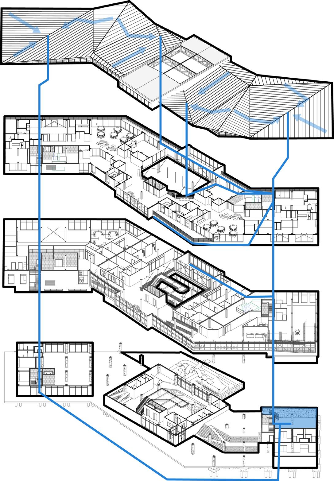
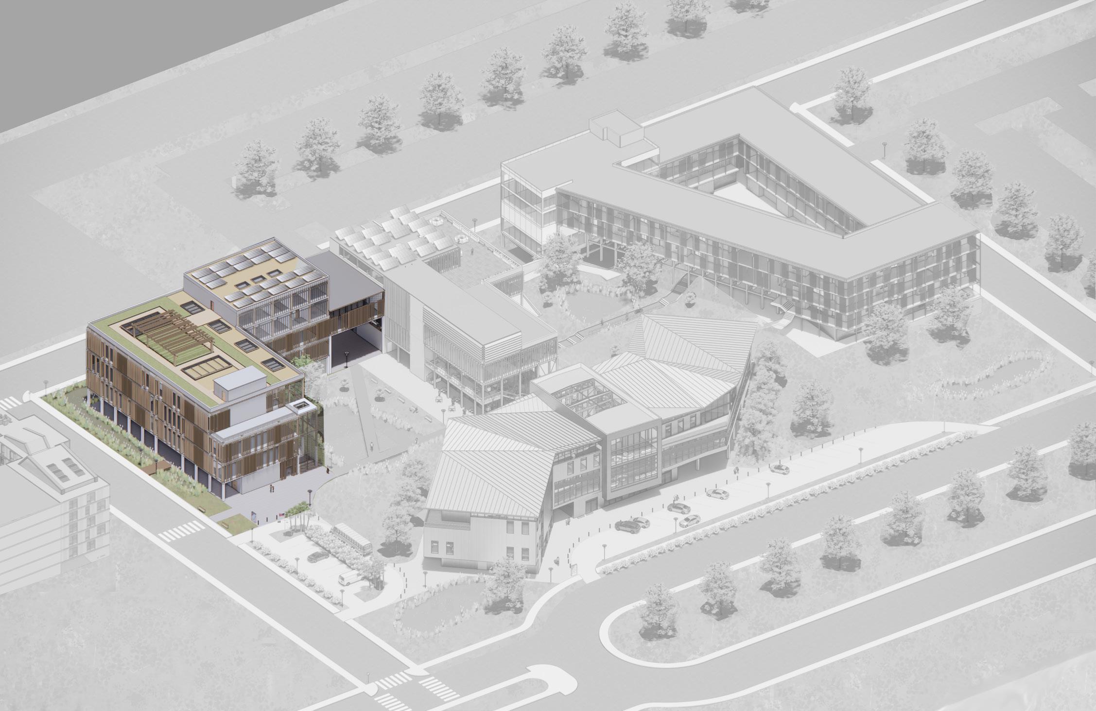
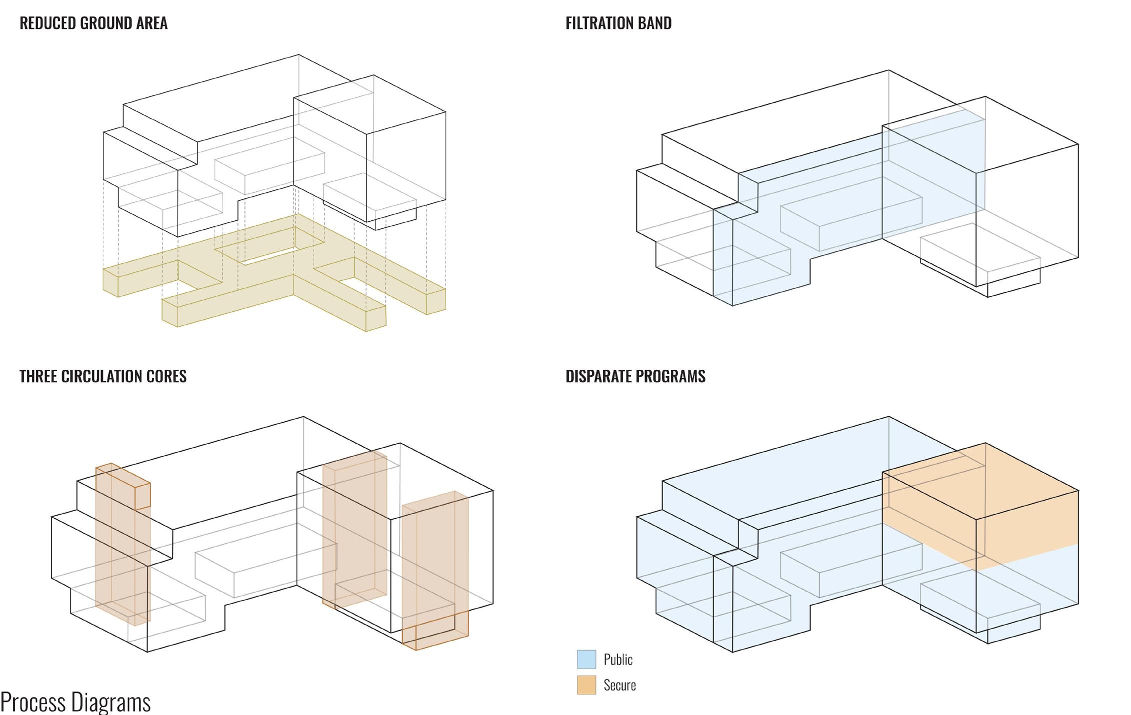
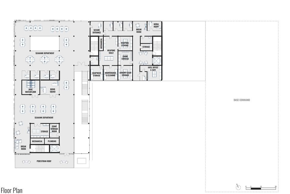
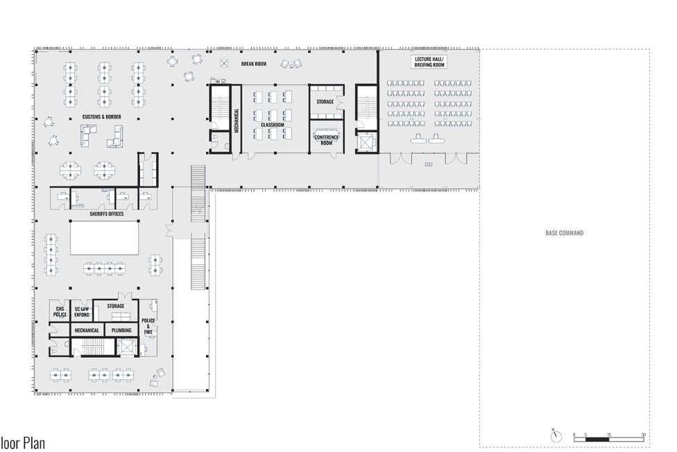
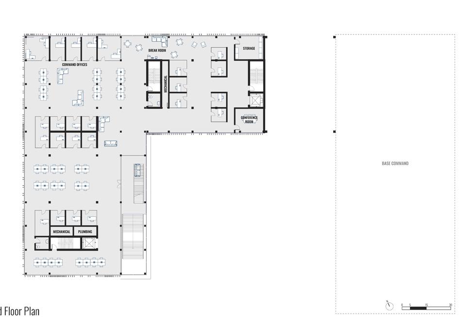
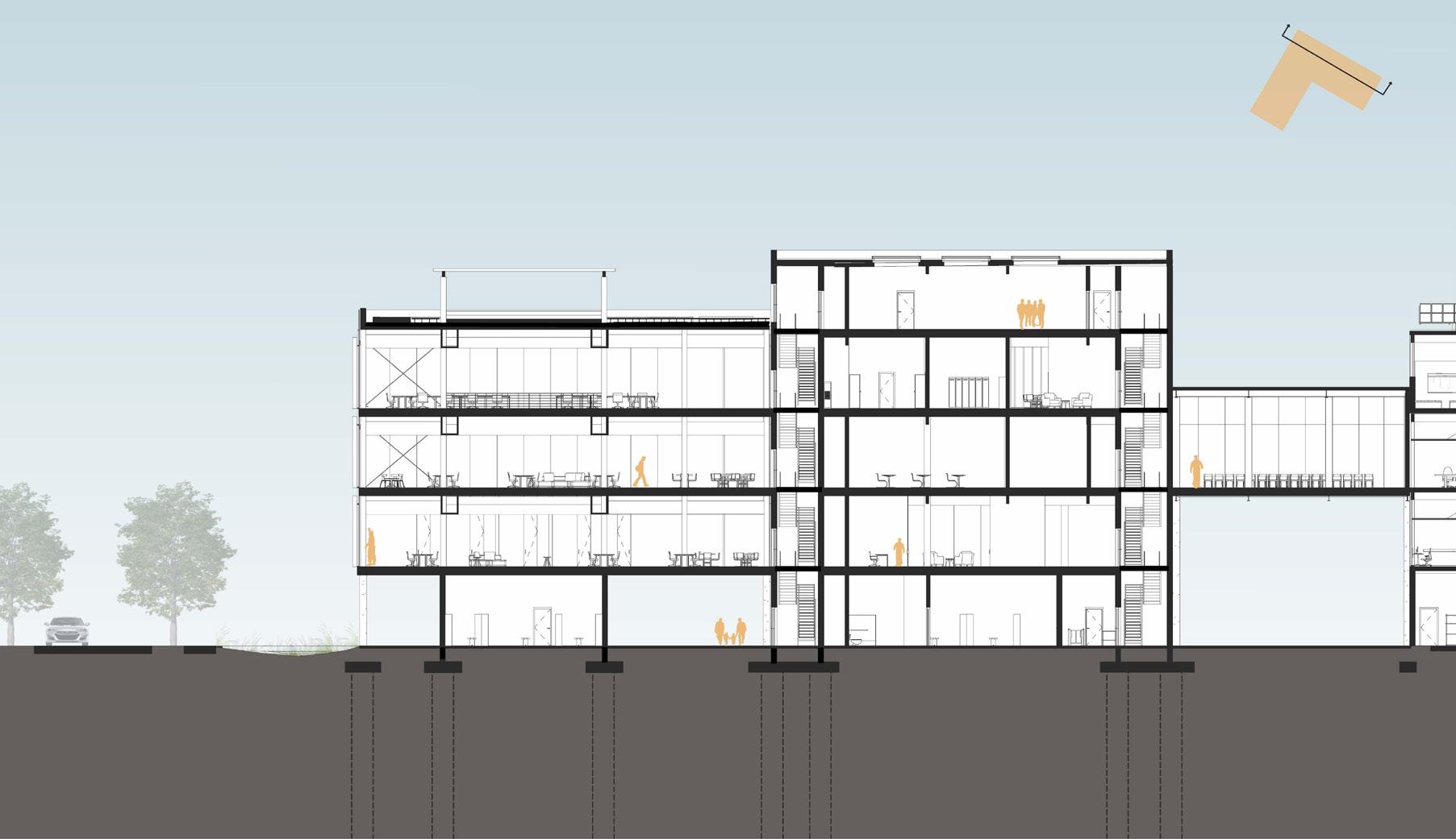
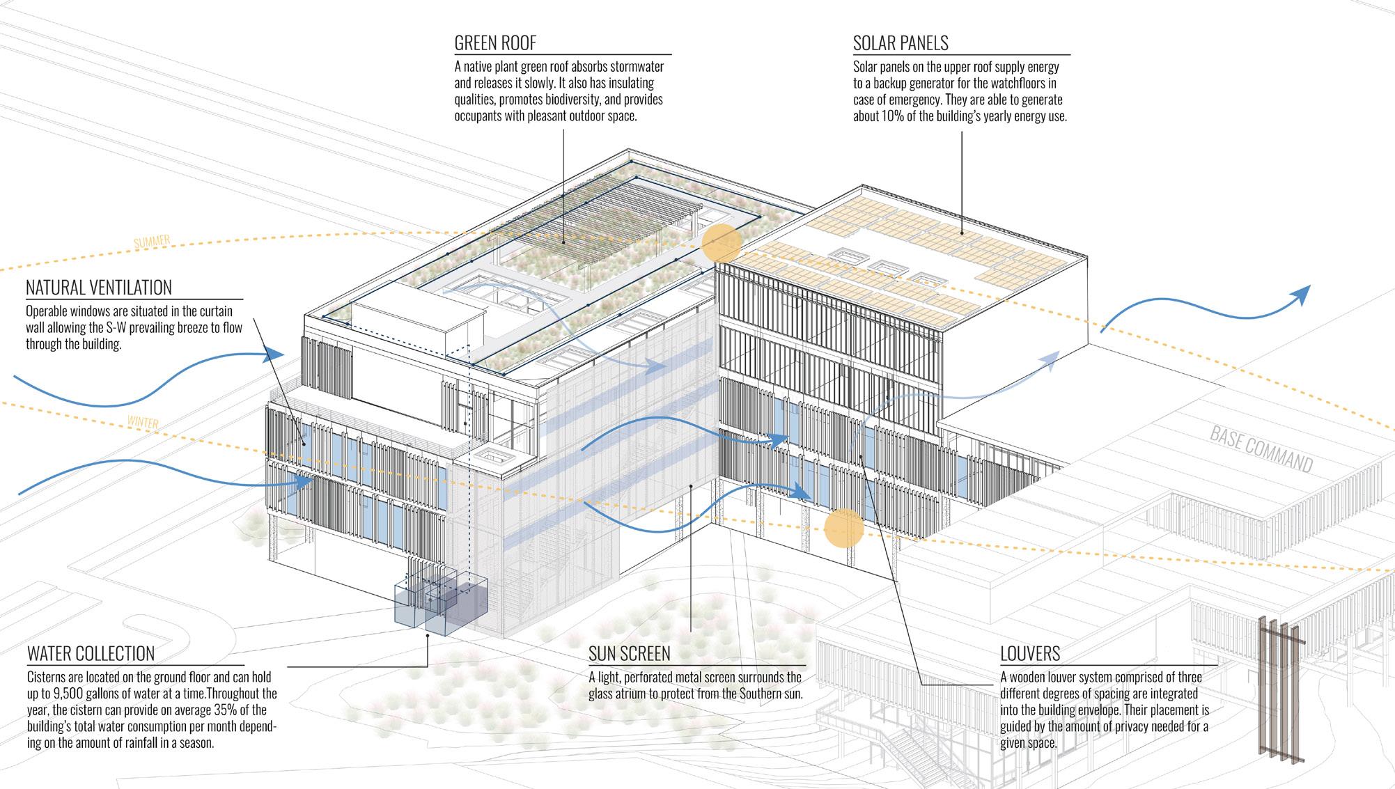
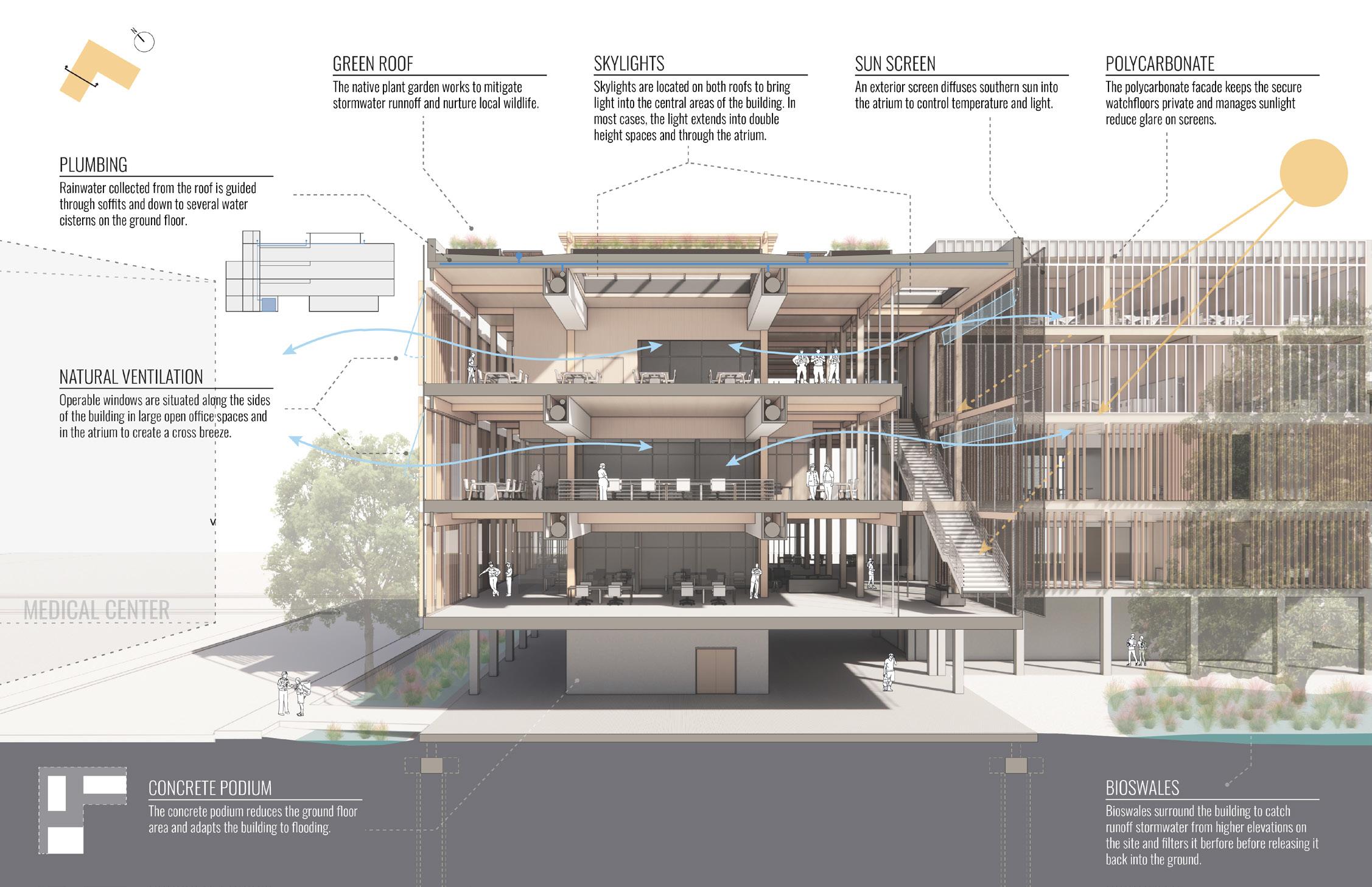
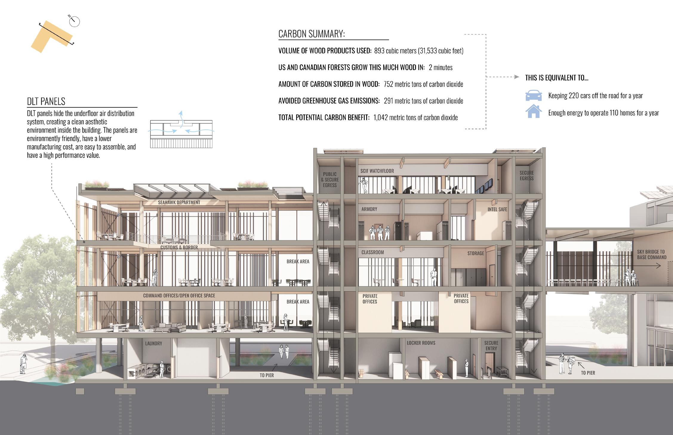
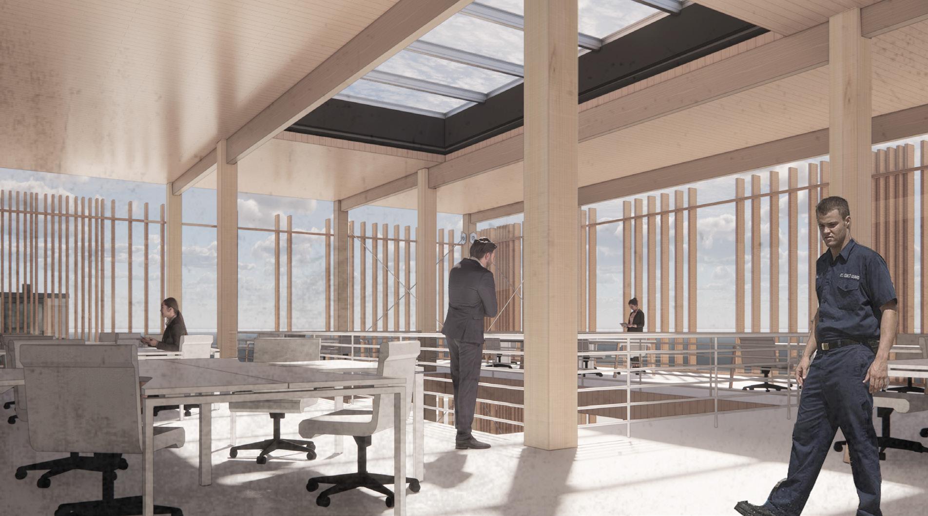
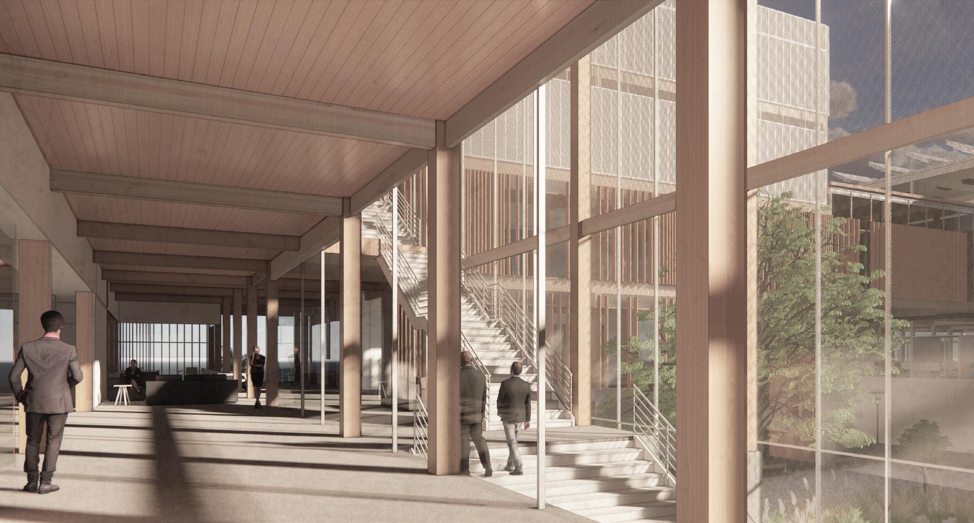
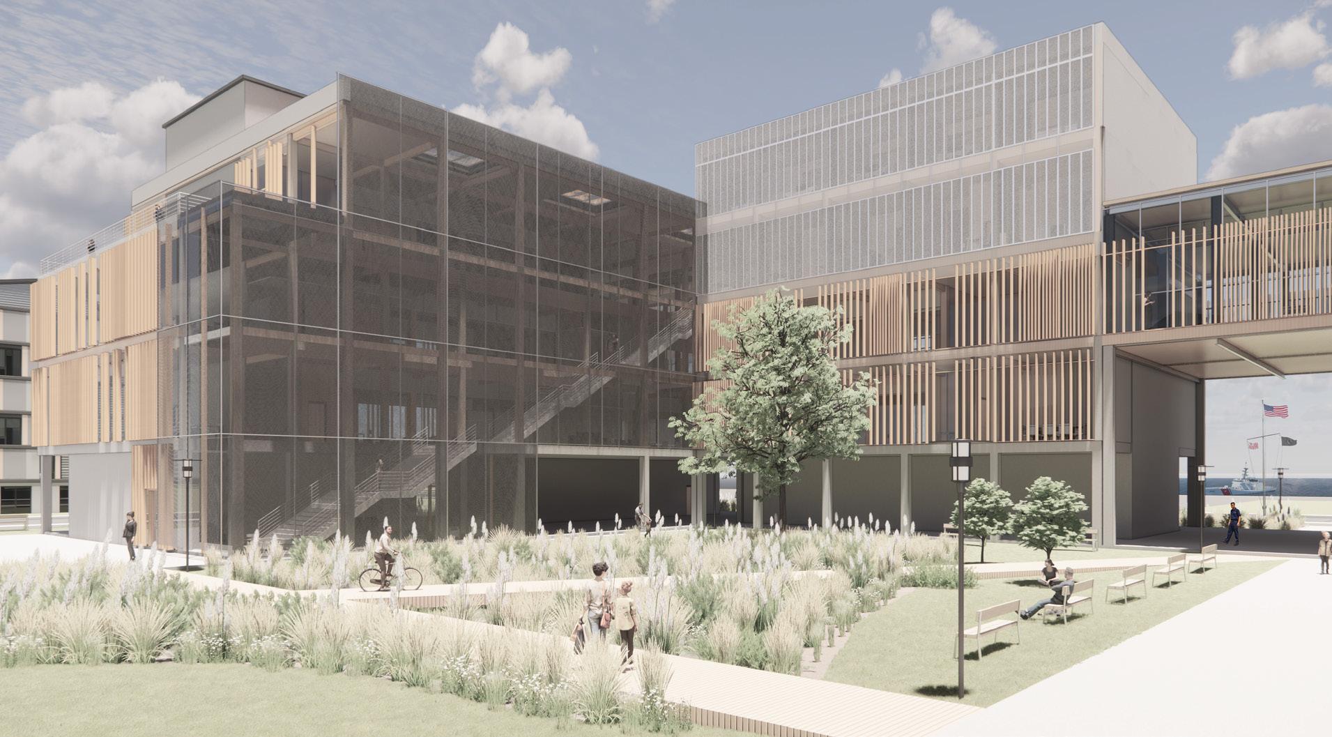
The Sector Command building has the unique condition of serving as the public entrance to the site while also housing the Coast Guard’s most secure programming. The project’s primary goal was to create a building that integrates public and secure programming into a cohesive space. We consistently referred to the larger site theme of filtration throughout the design process. The structural systems and programming strategies work in tandem to establish spatial neighborhoods using egress cores, a centralized atrium, and continuous perimeter circulation paths. Furthermore, the building offers several environmental solutions, the most developed being a water management system that begins with the native plant garden on the roof and ends with a bioswale in the ground. The result is a building centered around a fluid relationship between the occupant and the earth.
306
SECTOR COMMAND | SYDNEY PARKER + EMMA GIBSON
SECTOR COMMAND LOCATION ON SITE
307 SUPERTEAM 4
CONCEPT DEVELOPMENT
PROCESS DIAGRAMS
308
SECTOR COMMAND | SYDNEY PARKER + EMMA GIBSON
DEGREES OF VISIBILITY DIAGRAM TRANSPARENT TRANSLUCENT OPAQUE
SYDNEY’S PREMISE DIAGRAM EMMA’S PREMISE DIAGRAM
309 SUPERTEAM 4
310 GROUND
SECTOR COMMAND | SYDNEY PARKER + EMMA GIBSON
FLOOR PLAN
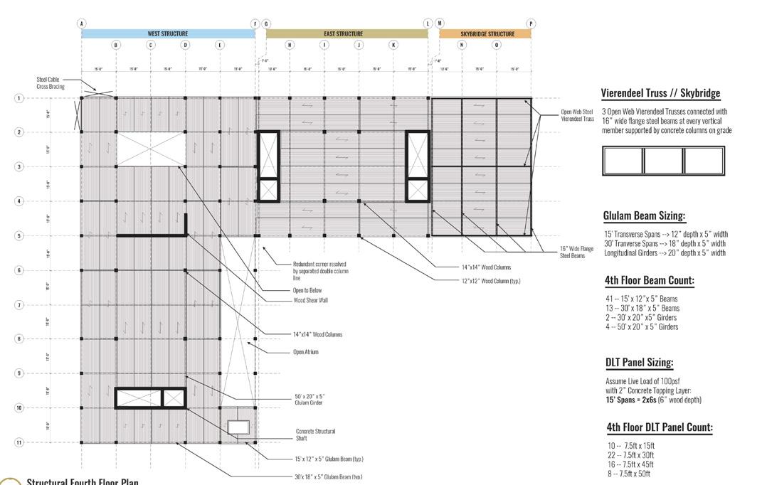
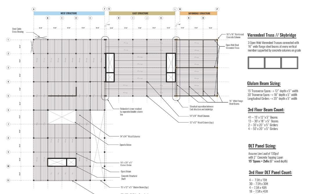
SECOND FLOOR PLAN THIRD FLOOR PLAN
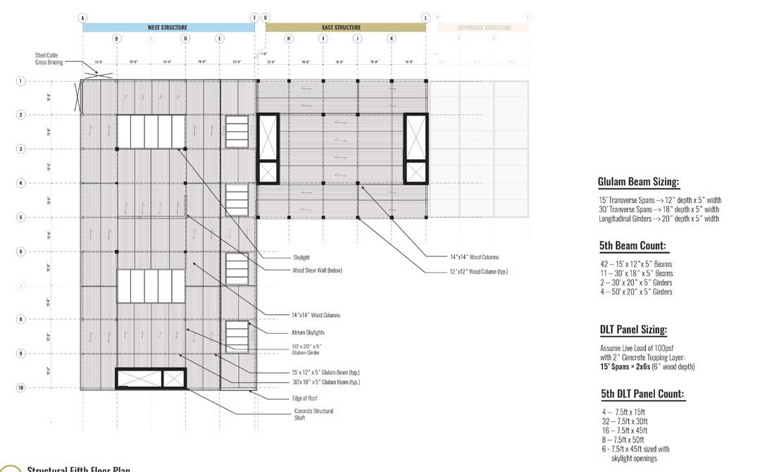
FOURTH FLOOR PLAN FIFTH FLOOR PLAN
311 SUPERTEAM 4
SIXTH
FLOOR PLAN
312 SECTOR COMMAND | SYDNEY PARKER + EMMA GIBSON
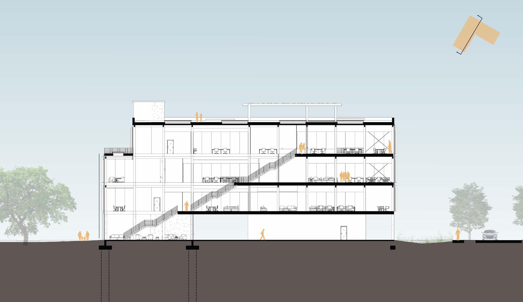
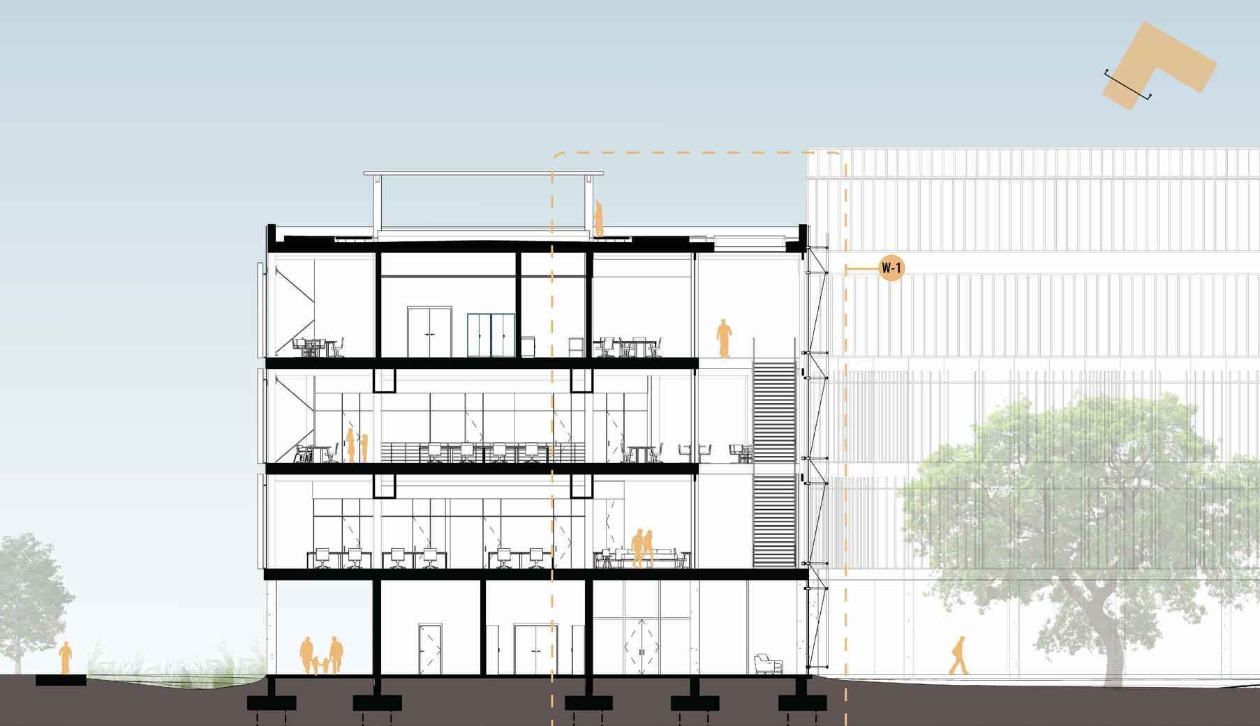
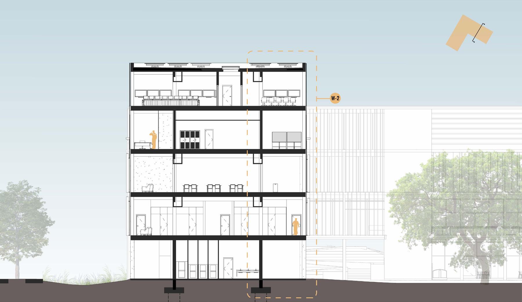
SECTIONS
313 SUPERTEAM 4
AXONOMETRIC LOAD TRACING DIAGRAM
AXONOMETRIC DIAGRAM
314
|
STRUCTURE STRUCTURAL
SECTOR COMMAND
SYDNEY PARKER + EMMA GIBSON
FOUNDATION AND GROUND FLOOR FRAMING PLAN SECOND FLOOR FRAMING PLAN
THIRD FLOOR FRAMING PLAN FOURTH FLOOR FRAMING PLAN
FIFTH FLOOR FRAMING PLAN
ROOF FRAMING PLAN
315 SUPERTEAM 4
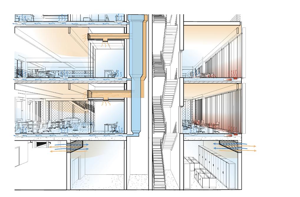
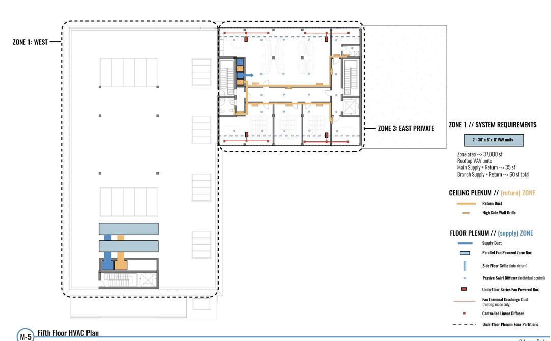
ENVIRONMENTAL SYSTEMS
SECTION PERSPECTIVE SHOWING MECHANICAL SYSTEMS MECHANICAL DISTRIBUTION DIAGRAM
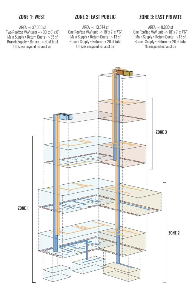
PASSIVE SYSTEMS DIAGRAM
316
SECTOR COMMAND | SYDNEY PARKER + EMMA GIBSON
GROUND FLOOR MECHANICAL PLAN SECOND FLOOR FRAMING PLAN
THIRD FLOOR FRAMING PLAN FOURTH FLOOR MECHANICAL PLAN
FIFTH FLOOR MECHANICAL PLAN
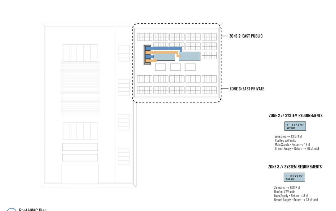
ROOF MECHANICAL PLAN
317 SUPERTEAM 4
ENVIRONMENTAL STRATEGIES + ANALYSIS
318
SECTOR COMMAND | SYDNEY PARKER + EMMA GIBSON
319 SUPERTEAM 4
320
SECTOR COMMAND | SYDNEY PARKER + EMMA GIBSON
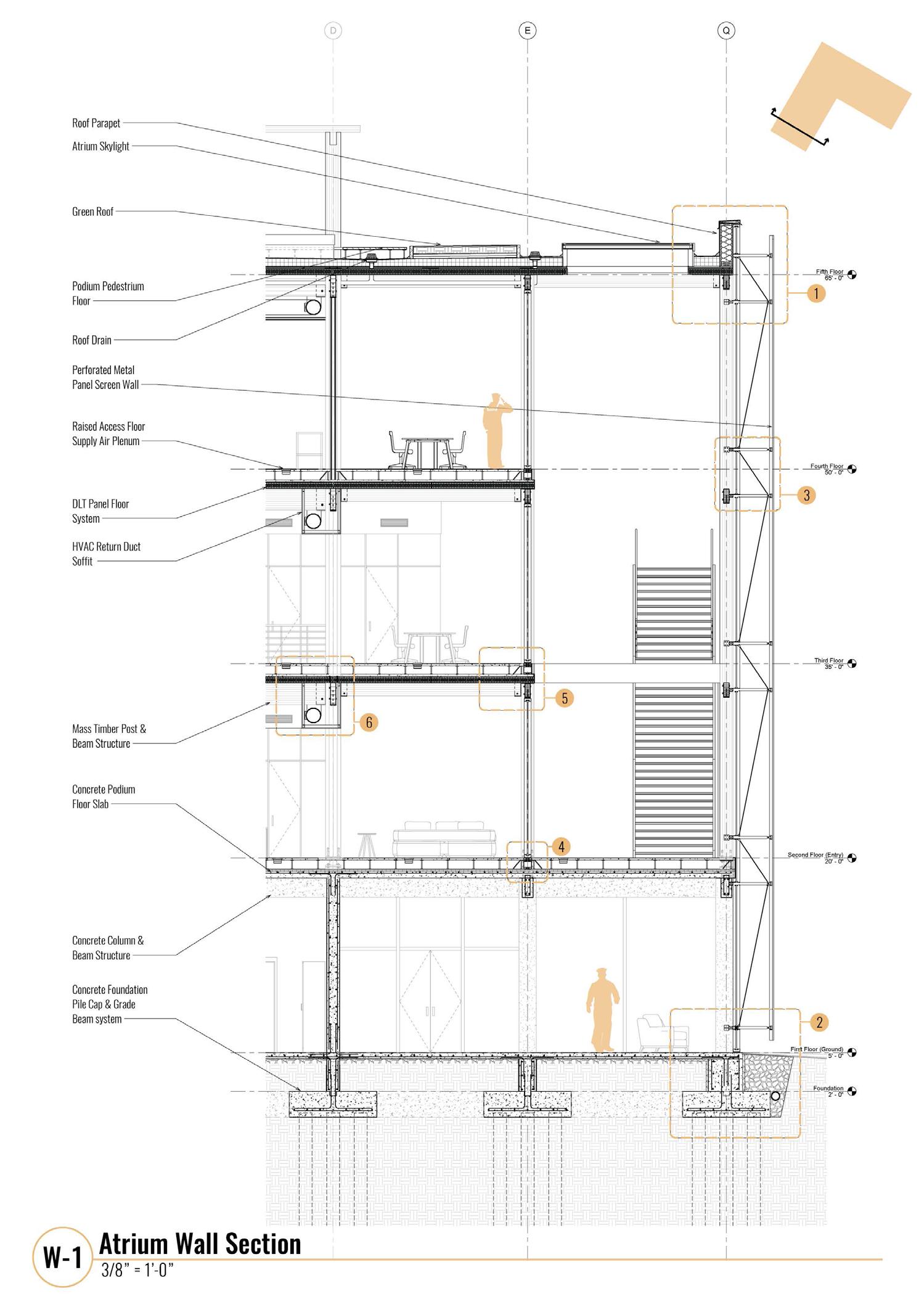
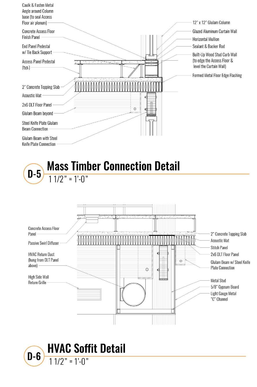
BUILDING ENVELOPE
321 SUPERTEAM 4
322
EXTERIOR VIEW FROM PIER
INTERIOR VIEW OF ATRIUM
SECTOR COMMAND | SYDNEY PARKER + EMMA GIBSON
323 SUPERTEAM 4
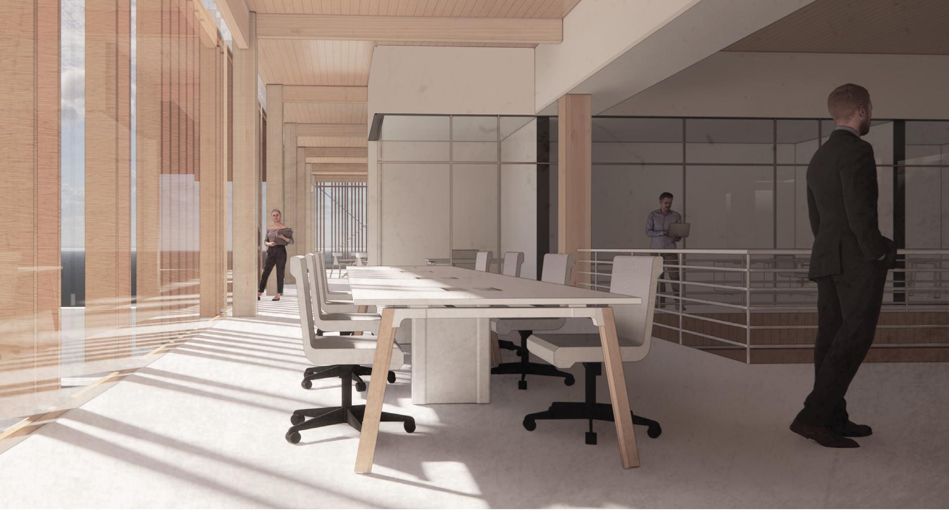
FOURTH FLOOR OPEN OFFICE
SECOND FLOOR CORRIDOR
324 SECTOR COMMAND |
+
SYDNEY PARKER
EMMA GIBSON
EXTERIOR VIEW OF GARDEN THIRD FLOOR OFFICE
325 SUPERTEAM 4
BASE COMMAND
FOR SUPERTEAM 4 SUB-MASTERPLAN
Premise
Building as a Filter Community + Occupant interaction

Context
Three essential aspects of this design are integration, resources, and community. How can we create a permeable highfunctioning space?
The Base Command program requires very private and public space. My premise focuses on how we can meet the program’s privacy needs while also supporting community and occupant interaction and integration while supporting user wellbeing.
Question
How can we create efficient, accessible spaces used to filter people, water, and light?
How can we design for the community without impeding on the importance of the program?
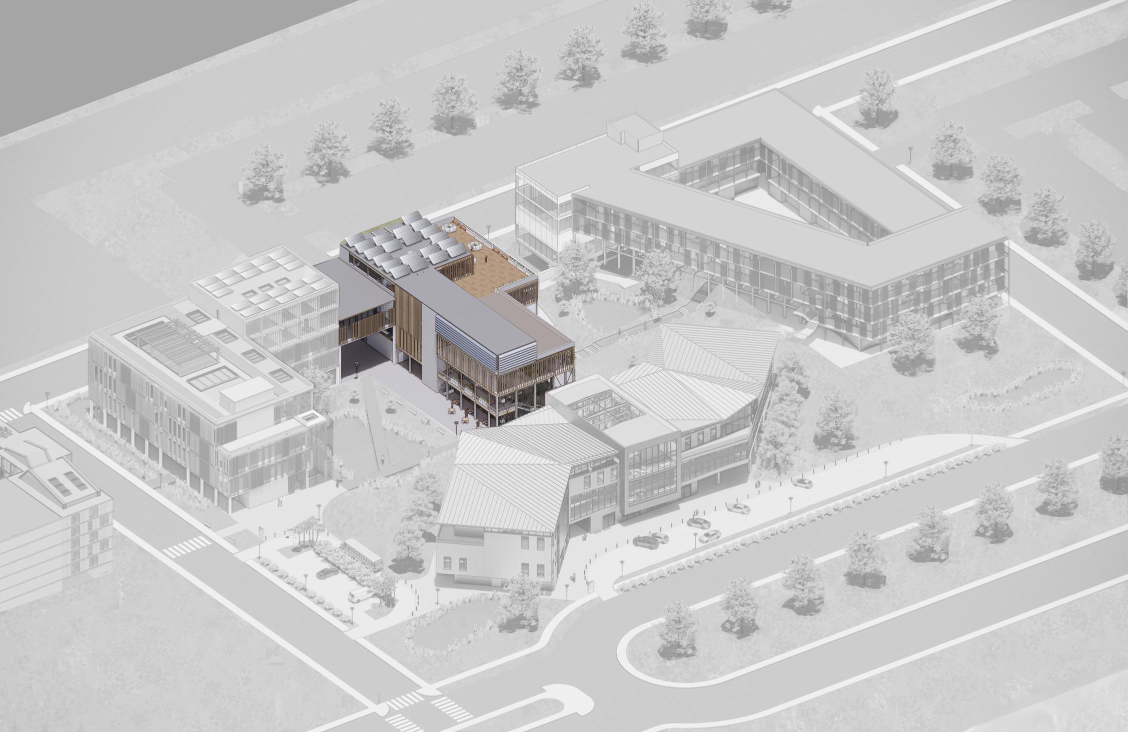
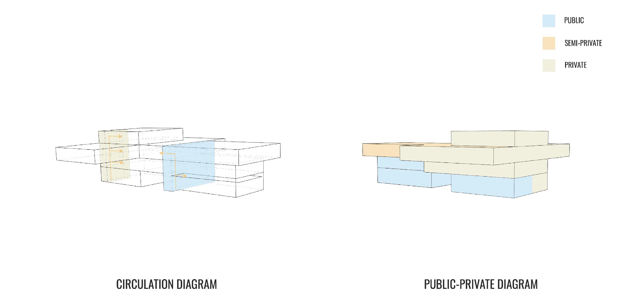
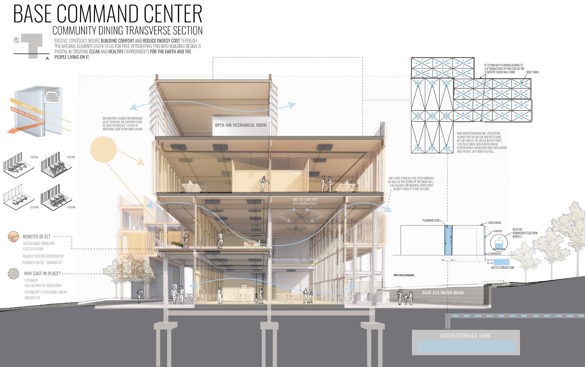
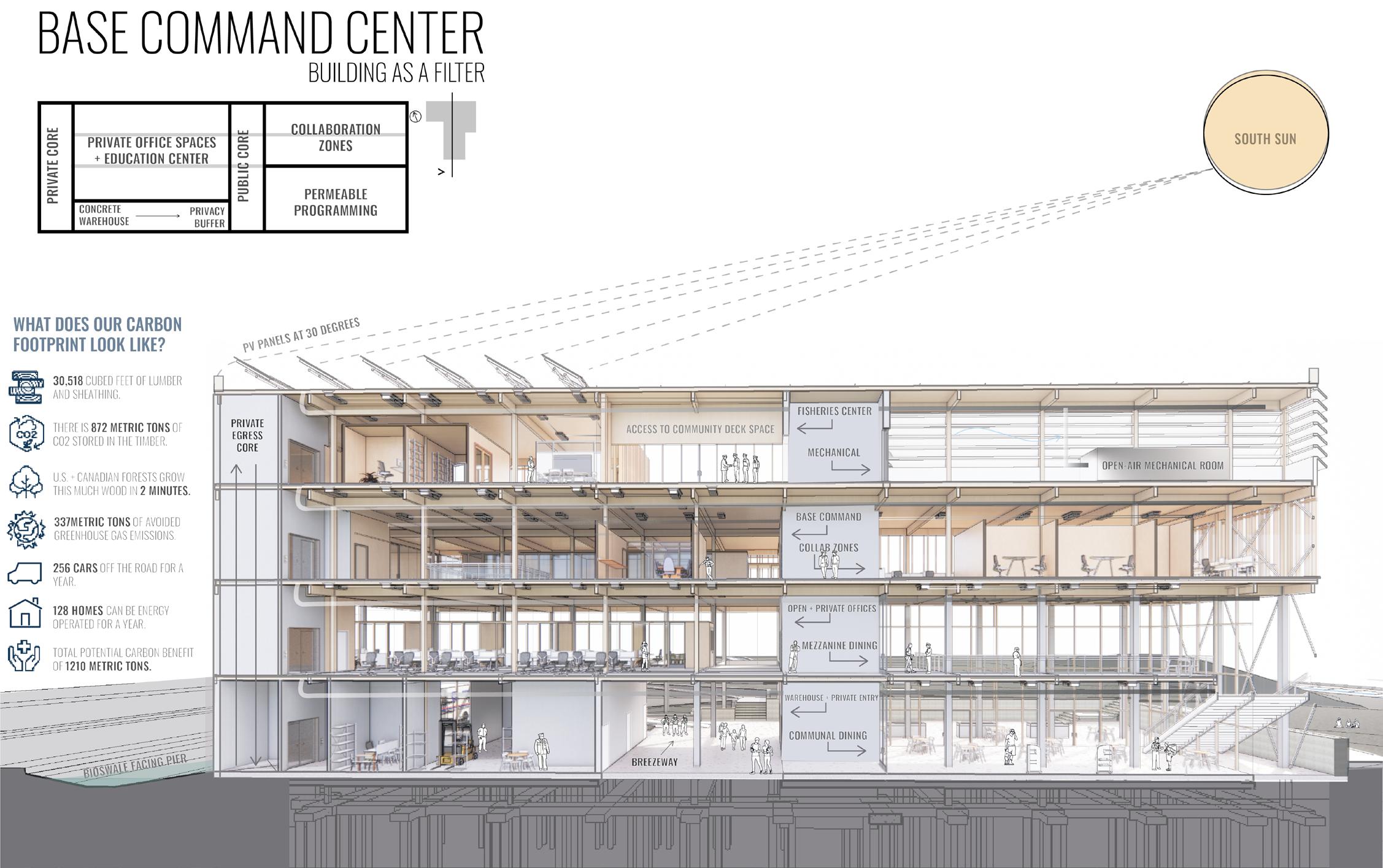
Base Command is the communal hub for the proposed Coast Guard site. It has a permeable presence on the site and acts as a transitional space from work to life. Our Statement
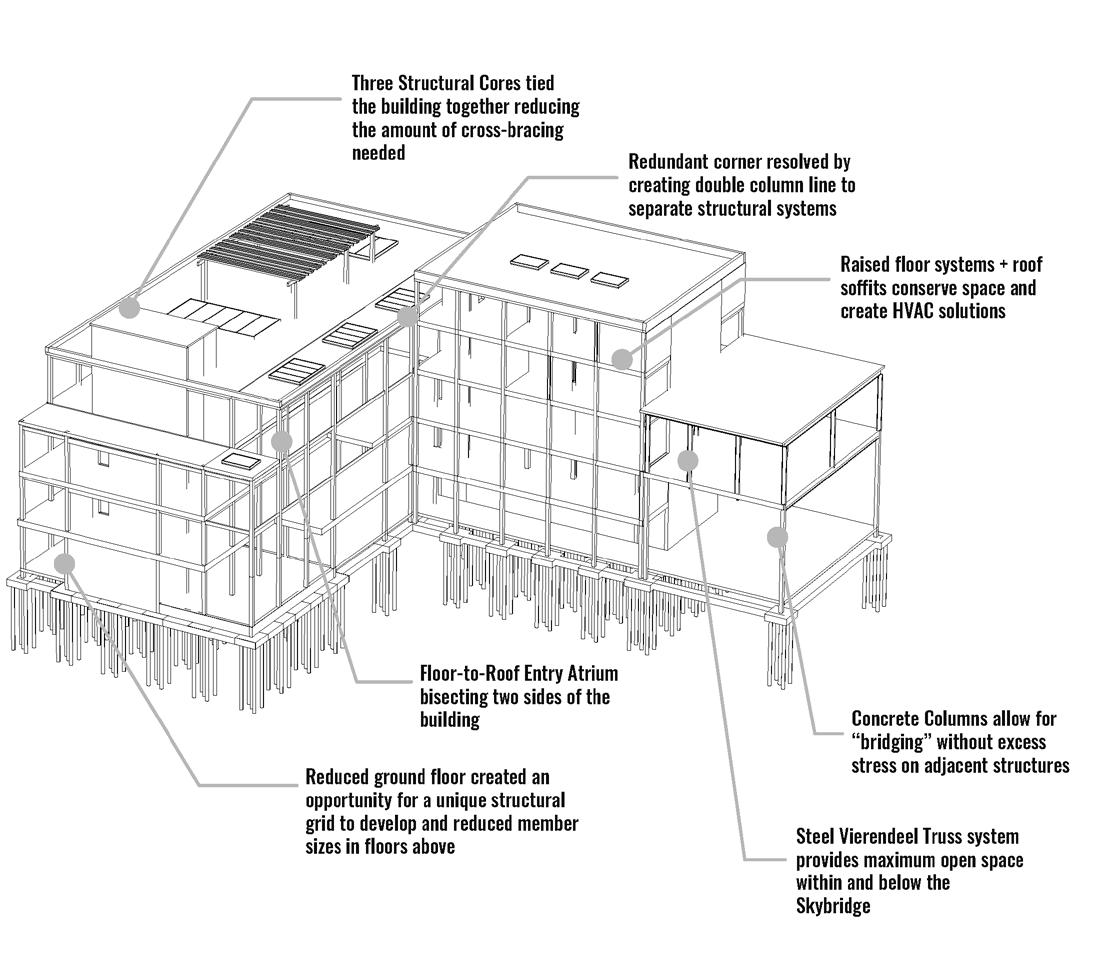
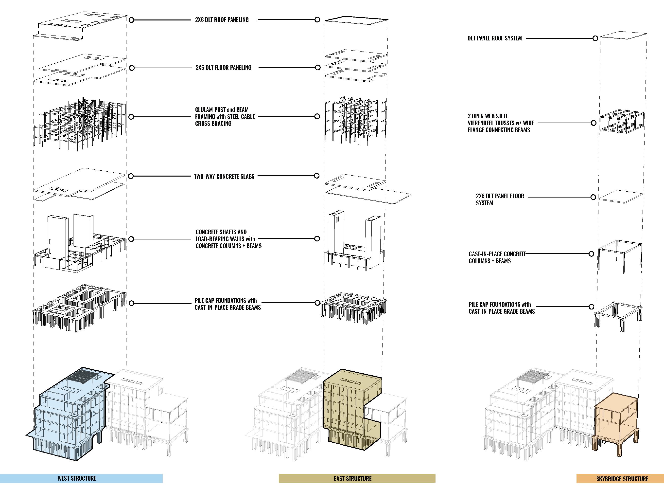
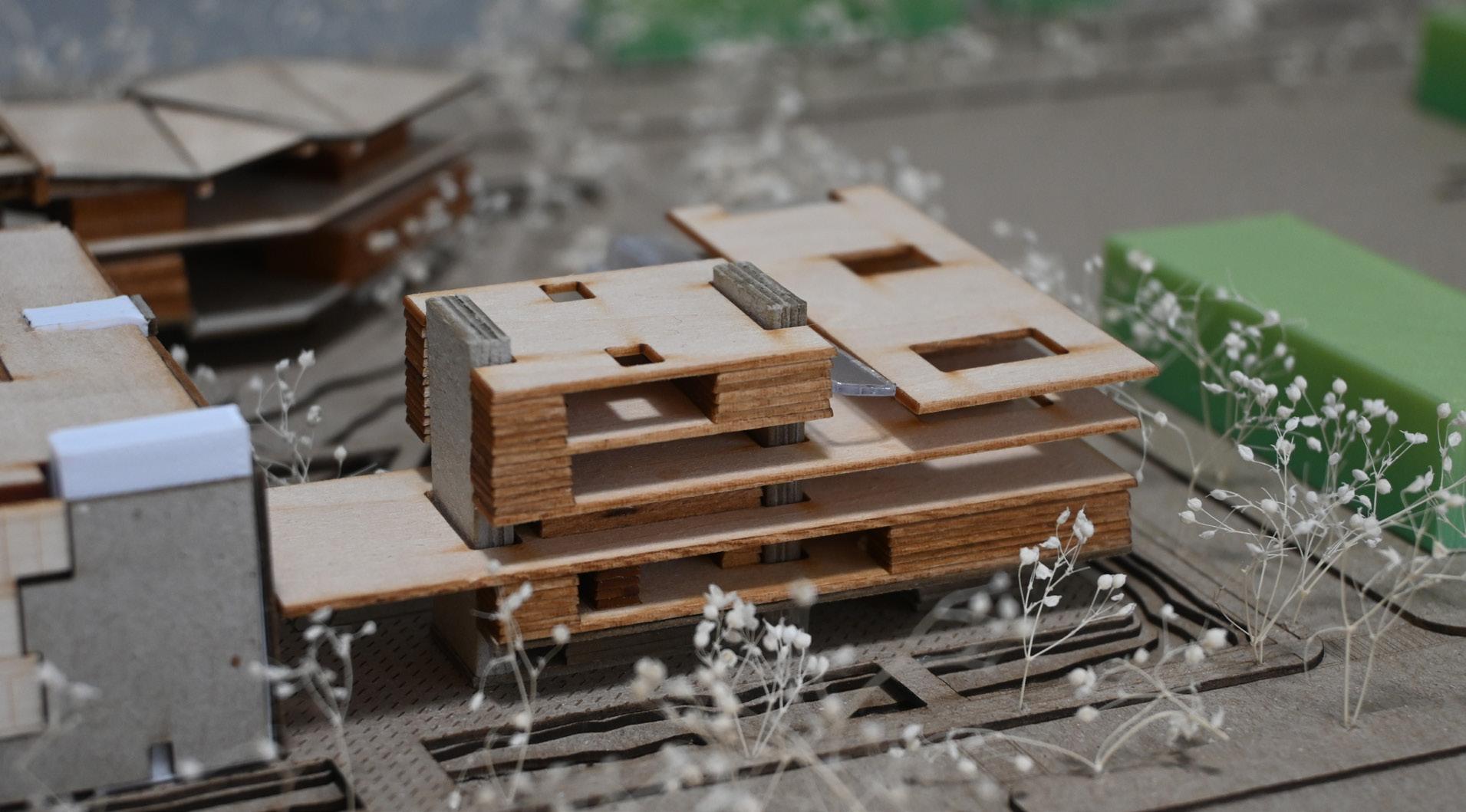
Base Command is the permeable programming of the proposed FLETC/USCG site that moves users, water, light, and the HVAC system throughout its cores to disperse users to their desired location. It provides a place of connection and airiness within the communal dining center located in the southern mass. The cores also act as circulation centers to divide users from public to private spaces while maintaining a sense of security associated with the Base Command and Sector Command. A sky bridge connects the base and sector command to allow for shared programming. The base command structure consists of a concrete foundation, beam, and column system, that transforms into an aesthetically pleasing timber glulam system with five-ply CLT floors and a three-ply CLT roof—finishing off with a curtain wall system that wraps the entirety of the structure. These decisions allow for a visual and physical connection for the public and private users of the site.
326
BASE COMMAND | JESSICA
LONGHURST + KIMANI GRAYSON
JESSICA LONGHURST
KIMANI GRAYSON
BASE COMMAND LOCATION ON SITE
327 SUPERTEAM 4
CONCEPT DEVELOPMENT
328
BASE
COMMAND | JESSICA LONGHURST + KIMANI GRAYSON
329 SUPERTEAM 4
330
BASE COMMAND |
+
GRAYSON
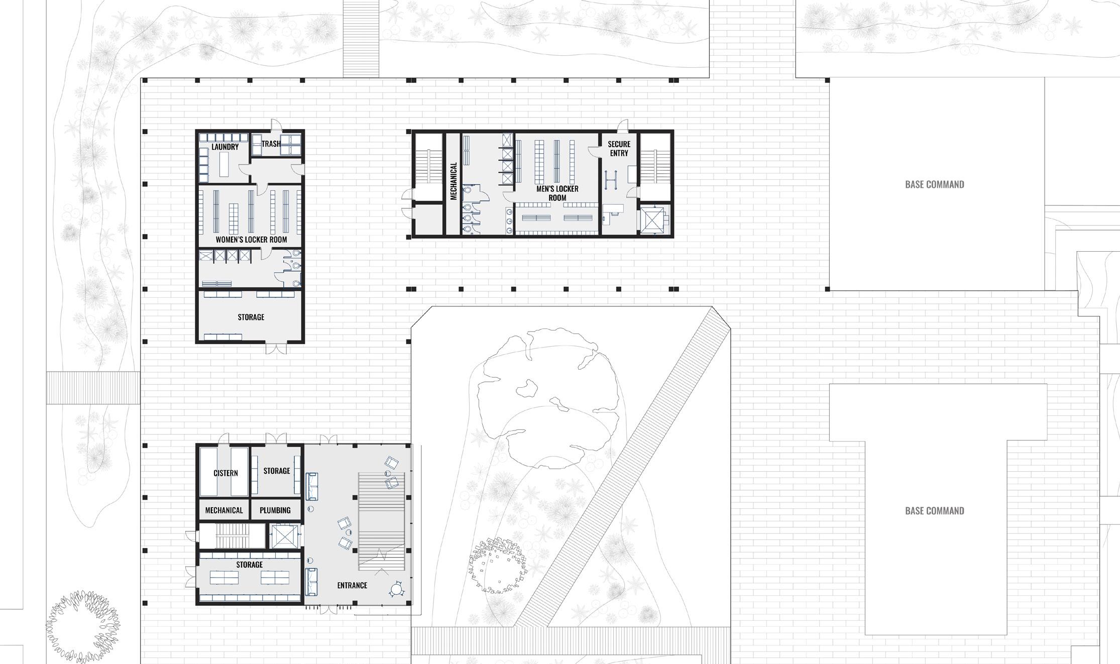
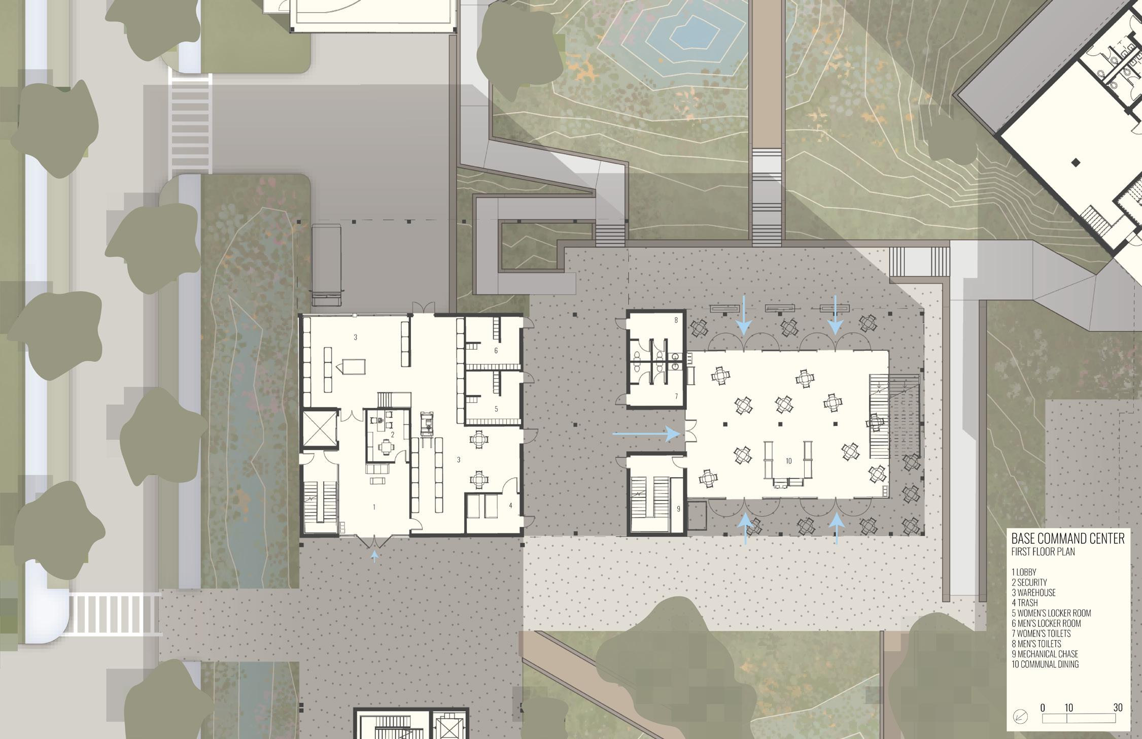
GROUND FLOOR PLAN
JESSICA LONGHURST
KIMANI
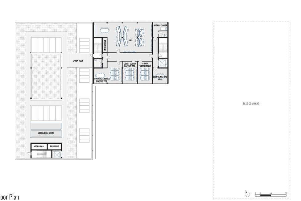
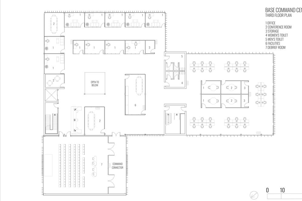
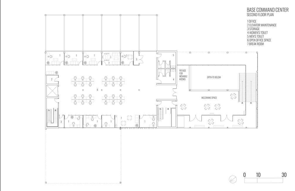
SECOND FLOOR PLAN THIRD FLOOR PLAN
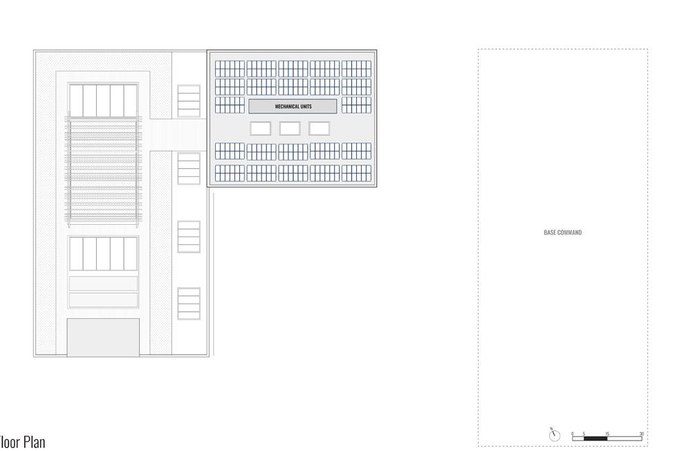
FOURTH FLOOR PLAN
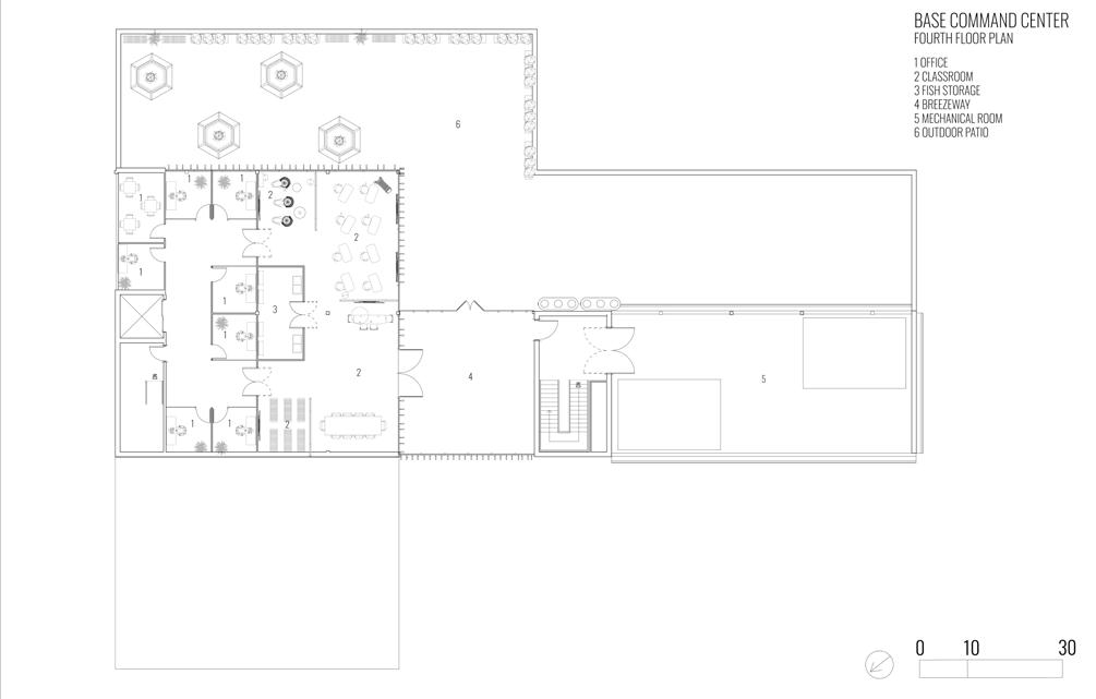
ROOF PLAN
331 SUPERTEAM 4
6” STORM WATER DRAINS LEADING TO A 6” DOWN SPOUT AT THE EDGE OF THE CONCRETE SHEAR WALL CORE ROOF DRAIN BASE COMMAND CENTER ROOF PLAN 0 10 30
332 BASE COMMAND | JESSICA
+ KIMANI GRAYSON
LONGHURST
333 SUPERTEAM 4
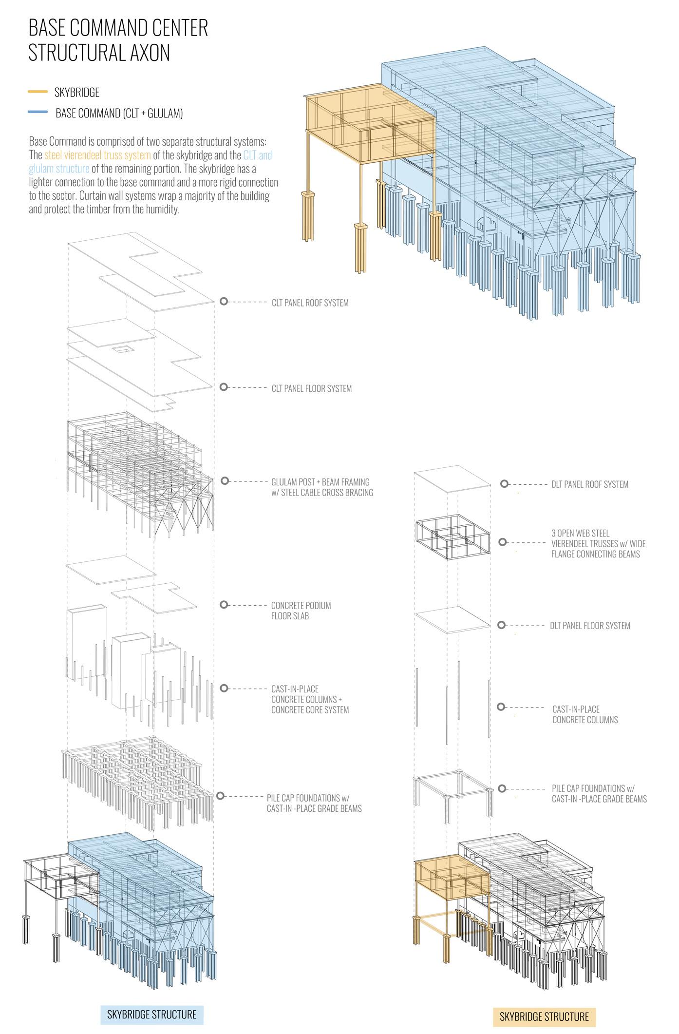
STRUCTURE
STRUCTURAL AXONOMETRIC DIAGRAM
334
BASE COMMAND | JESSICA LONGHURST + KIMANI GRAYSON
THIRD FLOOR FRAMING
335 SUPERTEAM 4 A B C D 2 4 6 7 8 9 10 11 12 13 ADDITIONAL NOTES 30’ 0” 30’ 30’ 15’ 0” 15’ 0” 15’ 0” 15’ 0” 15’ 0” 14’ 3” 15’ 7” 11’ 15’ 0” 15’ 0” 15’ 0” 8’ 8” BASE COMMAND CENTER FOUNDATION FRAMING PLAN CONCRETE SHEAR WALL CORE 60 X 60 X 24 CONCRETE FOUNDATION PILES 6” CONCRETE SLAB W/ FOOTINGS CONCRETE SHEAR WALL CORE 6” CONCRETE SLAB W/ FOOTINGS 51 CONCRETE PILE CAPS 2 CONCRETE SHEAR WALL CORES 39 CONCRETE COLUMNS 2 CONCRETE FOUNDATION SLABS 85 CONCRETE GRADE BEAMS 204 CONCRETE PILES FOUNDATION AND GROUND FLOOR FRAMING PLAN ADDITIONAL NOTES A B C D 1 2 3 4 5 6 7 8 9 10 11 12 13 30’ 0” 30’ 0” 30’ 0” 15’ 0” 15’ 0” 15’ 0” 15’ 0” 15’ 0” 14’ 3” 15’ 7” 11’ 15’ 0” 15’ 0” 15’ 0” 8” BASE COMMAND CENTER LEVEL 1 FRAMING PLAN 30 15 X 30 15 30 15 30 15 30 15 30 15 30 15 30 30 15 30 15 30 15 30 15 30 15 X 30 15 30 15 30 15 30 15 30 15 30 11 30 15 20 11 20 15 X 30 15 30 15 20 9 10 20 4” STEEL CROSS BRACING EXTERIOR & INTERIOR STARS TO BELOW DOUBLE HEIGHT SPACE @ 30’ CONCRETE SHEAR WALL CORE DOUBLE HEIGHT SPACE @ 30’ CONCRETE SHEAR WALL CORE STAIRS BELOW 6” X 18” CONCRETE BEAM, TYP. 12” X 12” CONCRETE COLUMN, TYP. STAIRS BELOW MEZZANINE ABOVE GRADE @ 15’ 6” CONCRETE SLAB W/ FOOTINGS 2 CONCRETE SHEAR WALL CORES 39 CONCRETE COLUMNS 21 HORIZONTAL CONCRETE BEAMS 25 VERTICAL CONCRETE BEAMS 4 STEEL CROSS BRACES 6” X 18” GLULAM BEAMS 9 HORIZONTAL GLULAM BEAMS 12 VERTICAL GLULAM BEAMS SECOND FLOOR FRAMING PLAN ADDITIONAL NOTES C 1 2 3 4 5 6 8 10 11 12 13 30’ 0” 30’ 0” 30’ 15’ 0” 15’ 15’ 15’ 0” 15’ 0” 14’ 3” 15’ 7” 11’ 0” 15’ 0” 15’ 15’ 8” BASE COMMAND CENTER LEVEL 3 FRAMING PLAN 5 30 15 30 15 30 15 X 30 15 30 15 30 15 30 15 30 15 30 15 30 15 30 15 30 15 30 15 30 30 30 15 30 15 30 30 11 30 15 30 15 30 15 X 30 15 30 15 30 15 30 4” STEEL CROSS BRACING CONCRETE SHEAR WALL CORE STAIR BELOW 10’ X 15’ CLT FLOOR PANELS THIN 5 PLY THICKNESS & 2 1/2” CONCRETE TOP LAYER 8” X 8” WOOD COLUMNS 6” X 18” GLULAM BEAMS CONCRETE SHEAR WALL CORE STAIRS BELOW 2 CONCRETE SHEAR WALL CORES 33 HORIZONTAL GLULAM BEAMS 44 VERTICAL GLULAM BEAMS 4 STEEL CROSS BRACES 39 GLULAM COLUMNS 84 CLT FLOOR PANELS
PLAN ADDITIONAL NOTES A B C D 1 2 3 4 5 6 7 9 10 11 12 13 30’ 0” 30’ 0” 30’ 0” 15’ 0” 15’ 0” 15’ 0” 15’ 0” 15’ 0” 14’ 3” 15’ 11’ 0” 15’ 0” 15’ 0” 15’ 0” 8” BASE COMMAND CENTER LEVEL 4 FRAMING PLAN 30 15 30 15 30 15 30 15 30 15 30 15 X 30 15 30 15 30 10 30 15 30 15 30 15 30 30 CONCRETE SHEAR WALL CORE STAIRS BELOW 10’ X 15’ FLOOR PANELS THIN 5 PLY THICKNESS & 2 1/2” CONCRETE TOP LAYER 8” X 8” GLULAM COLUMNS 6” X 18” GLULAM BEAMS CONCRETE SHEAR WALL CORE STAIRS BELOW 2 CONCRETE SHEAR WALL CORES 16 HORIZONTAL GLULAM BEAMS 28 VERTICAL GLULAM BEAMS 23 GLULAM COLUMNS 39 CLT FLOOR PANELS 15 30 FOURTH FLOOR FRAMING PLAN ADDITIONAL NOTES CLT ROOF PANELS 10’ X 15’ IN DIMENSION THIN 3 PLY THICKNESS BASE COMMAND CENTER ROOF FRAMING PLAN 10 15 10 15 10 15 10 15 10 15 10 15 10 15 10 10 15 10 10 10 15 10 15 10 15 10 X 15 10 15 10 15 10 15 10 57 CLT ROOF PANELS ROOF FRAMING PLAN CLT ROOFING (+FLOOR) SYSTEM STEEL CABLE BRACING CORE WALL SYSTEM GLULAM BEAMS + COLUMNS SOURCE: Smartlam Columbia Falls, Montana WHY? Heavy timber confined within the protection of curtain wall system o ers more sustainable structural practice and does not compromise the wood aesthetic established by CLT Ceilings. SOURCE: Smartlam Columbia Falls, Montana WHY? The Delicateness of the nanawall curtain wall is not capable of handling the dead and live loads of the overhead structure without cross bracing. SOURCE: Caste in place (as well as concrete columns and beams.) WHY? Reinforced concrete walls stabilize the lightness of the curtain wall systems used on both the north and south portions of the building. SOURCE: Tie Down Engineering Atlanta, GA WHY? CLT ers clean, seamless, spans of timber that is easily accepted by other wooden members such as glulam beams. BASE COMMAND CENTER LOAD TRACING DIAGRAM POINT LOADS HORIZONTAL LOAD DISTRIBUTION
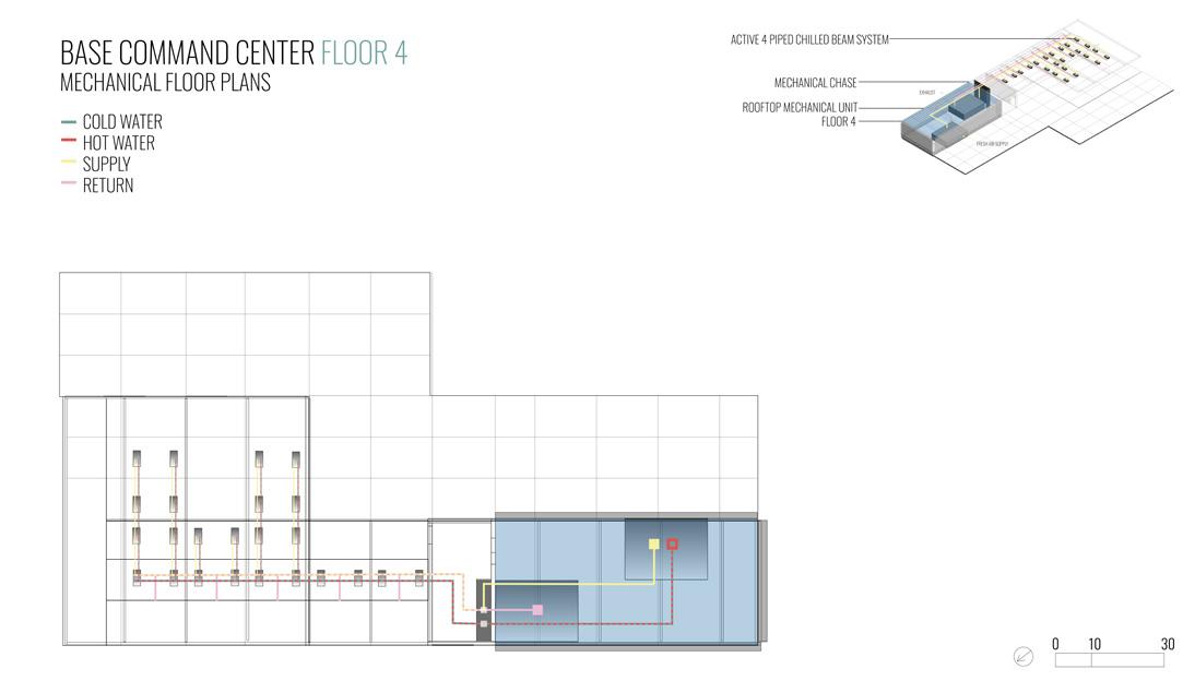
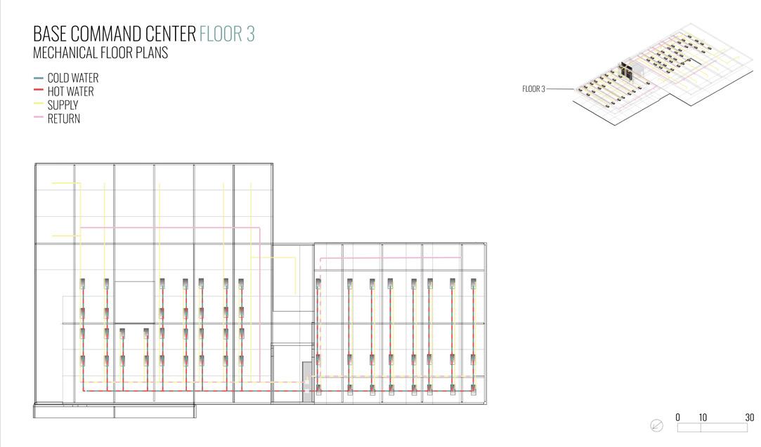
MAIN SUPPLY DUCT SIZE: 20 IN2
MAIN RETURN DUCT SIZE: 20 IN2
WATER PIPES SIZE 1 INCH IN DIAMETER
ACTIVE CHILLED BEAM SYSTEM:
A RADIATION/CONVECTION HVAC SYSTEM DESIGNED TO HEAT AND COOL LARGE BUILDINGS.
ACTIVE CHILLED BEAMS HAVE DUCTWORK SUPPLIED PROVIDING A SPECIFIC AMOUNT OF PRIMARY AIR TO THE PRESSURIZED PLENUM WITHIN THE DEVICE TO BE DISCHARGED THROUGH INDUCTION NOZZLES, MIX WITH ENTRAINED AIR, AND VENTILATE THE ROOM.
WHY ACTIVE CHILLED BEAMS?
ALLOWS FOR SMALLER DUCTWORK AND AIR-HANDLER UNITS THAN A TYPICAL VAV SYSTEM
CAN ACHIEVE RELATIVELY LOW SOUND LEVELS
USES SIGNIFICANTLY LESS ENERGY THAN A VAV SYSTEM
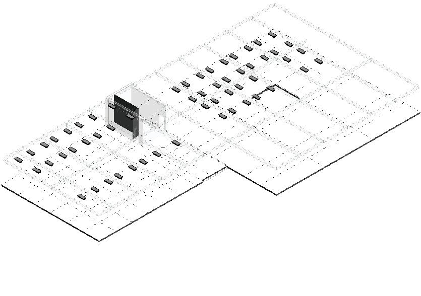
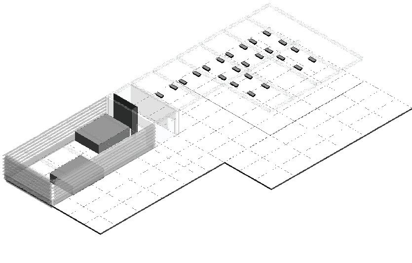
336 BASE COMMAND CENTER MECHANICAL AXON ACTIVE 4 PIPED CHILLED BEAM SYSTEM
LARGE FAN AIR CIRCULATION FLOOR 2 FLOOR 1
CHASE COLD WATER HOT WATER SUPPLY RETURN FRESH AIR SUPPLY EXHAUST
UNIT
FLOOR 4 FLOOR 3
MECHANICAL
ROOFTOP MECHANICAL
2 UNITS AT 300 SQFT EACH CONTAINING:
CHILLER HEAT PUMP AIR HANDING UNIT W/ DEHUMIDIFICATION FAN ROOM EXHAUST LOUVERS FRESH AIR INTAKE LOUVERS
PRIMARY AIR ACTIVE CHILLED BEAM SYSTEM INDUCED AIR COIL INDUCED AIR + PRIMARY AIR MECHANICAL
BASE COMMAND | JESSICA LONGHURST + KIMANI GRAYSON
SYSTEMS
AXONOMETRIC DIAGRAM
ENVIRONMENTAL
GROUND FLOOR MECHANICAL PLAN SECOND FLOOR FRAMING PLAN
THIRD FLOOR FRAMING PLAN FOURTH FLOOR MECHANICAL PLAN
337 SUPERTEAM 4
BUILDING ENVELOPE
338
BASE
|
COMMAND
JESSICA LONGHURST + KIMANI GRAYSON
339 SUPERTEAM 4 STRONG BACK
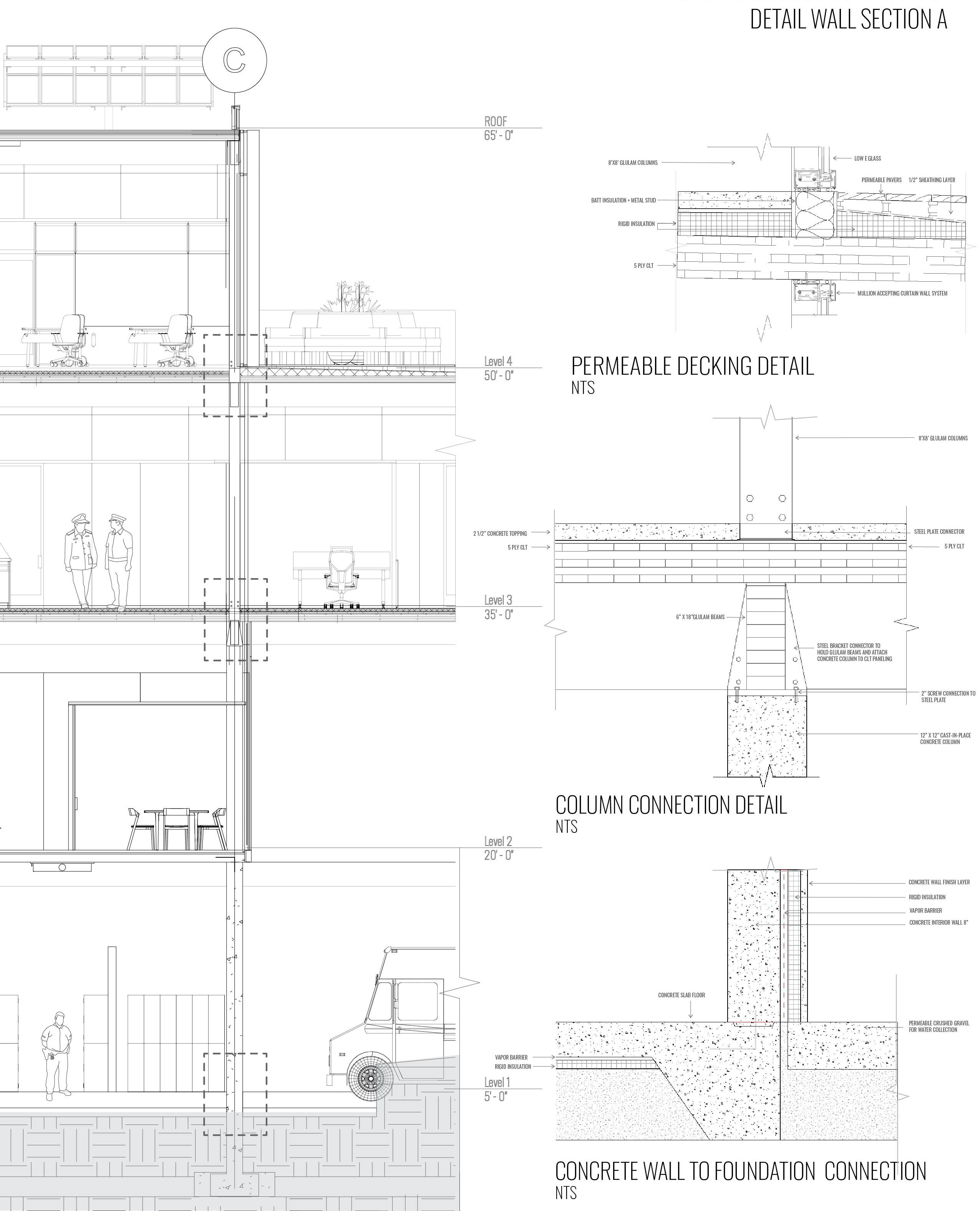
DETAIL
1 2 3 SUPPORT BAR MODULE RAIL TYP. MODULE DEPTH STRONG BACK MODULE RAIL TYP. RAIL SUPPORT ANGLE TYP. 30.00 MOUNTING SLEEVE SOLAR PANEL DETAIL 0 1 5
BASE COMMAND CENTER
WALL SECTION B COLUMN CONNECTION DETAIL 2 NTS ROOFING DETAIL 3 NTS NANA WALL CONNECTION DETAIL 1 NTS
340
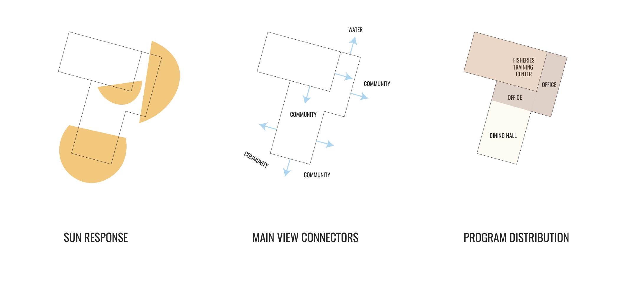
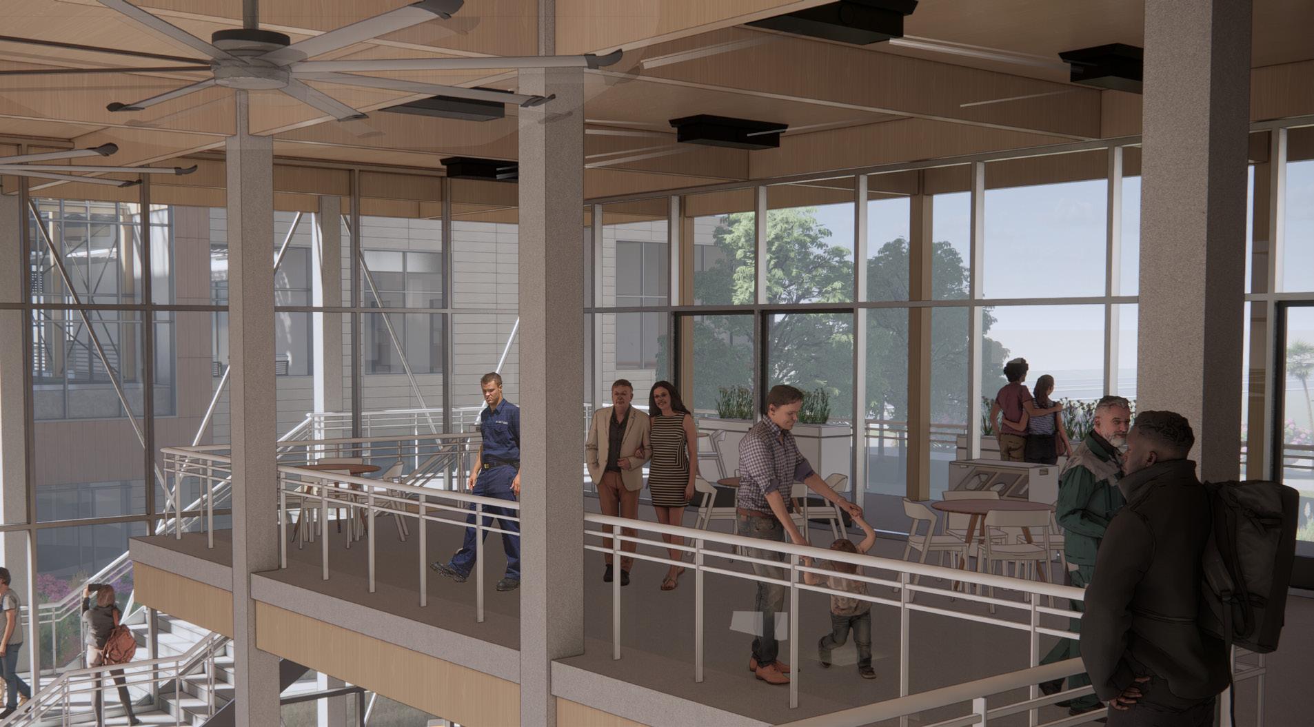
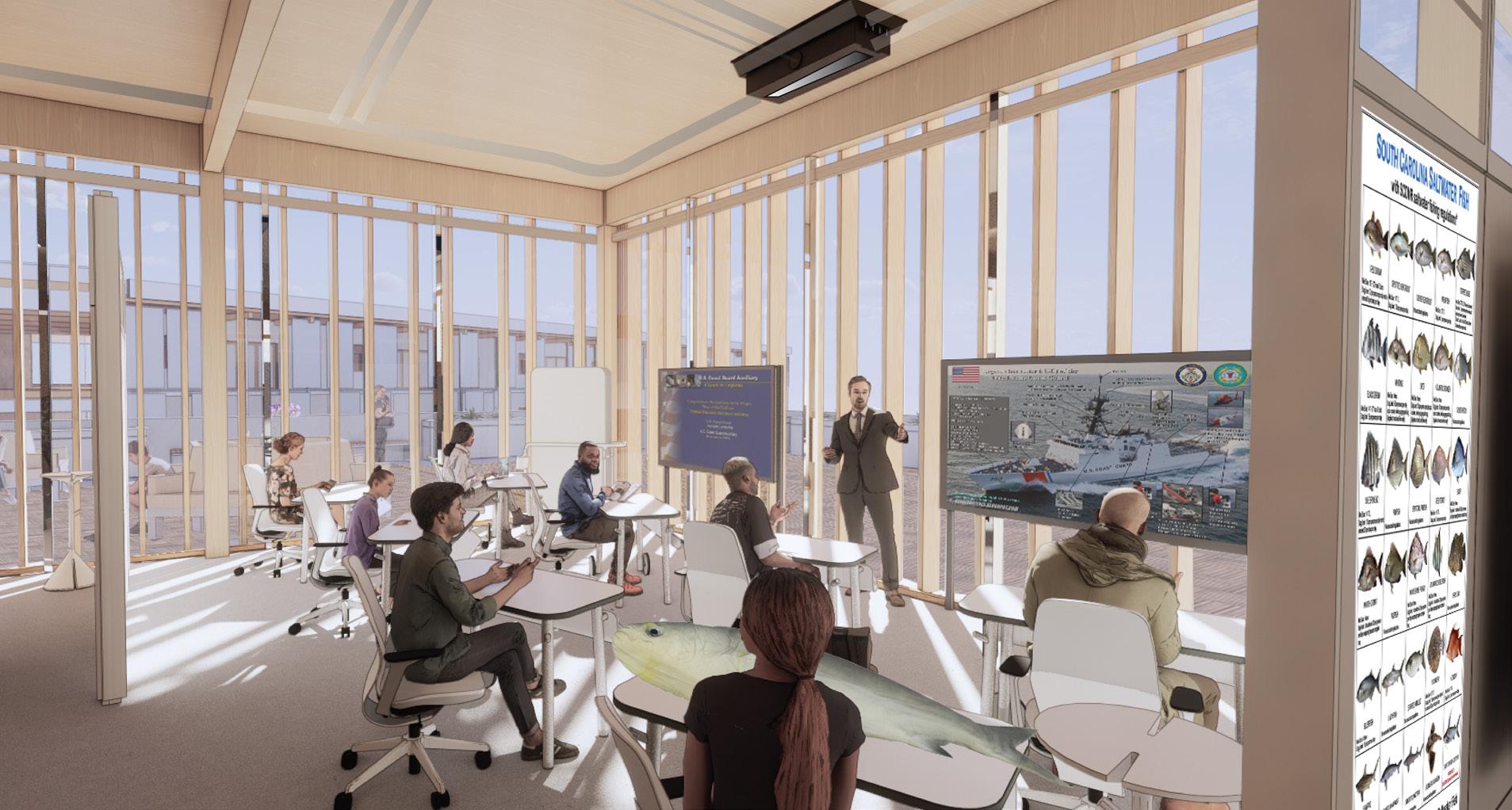
COMMUNAL DINING
FISHERIES CENTER
BASE COMMAND | JESSICA LONGHURST + KIMANI GRAYSON
341 SUPERTEAM 4
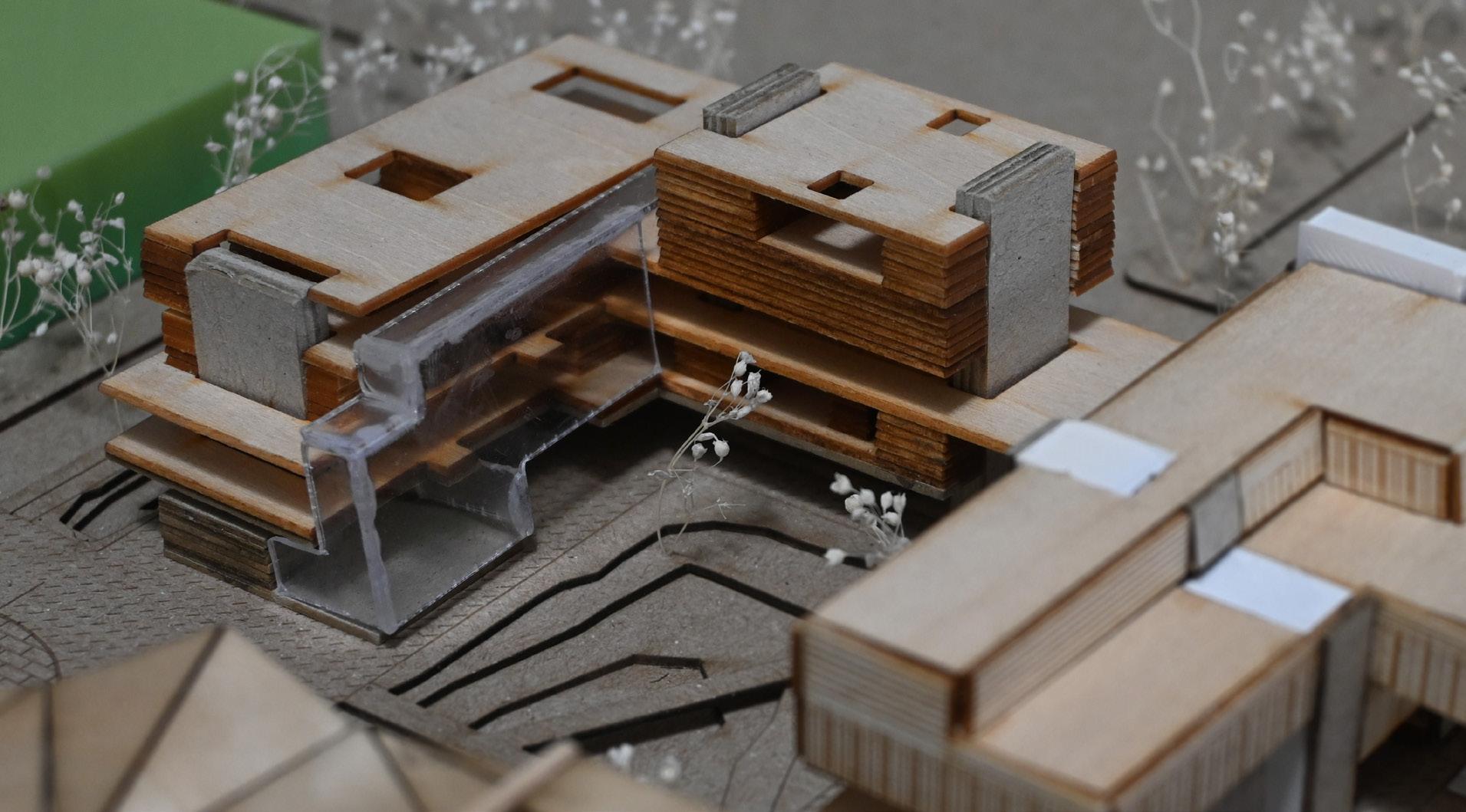
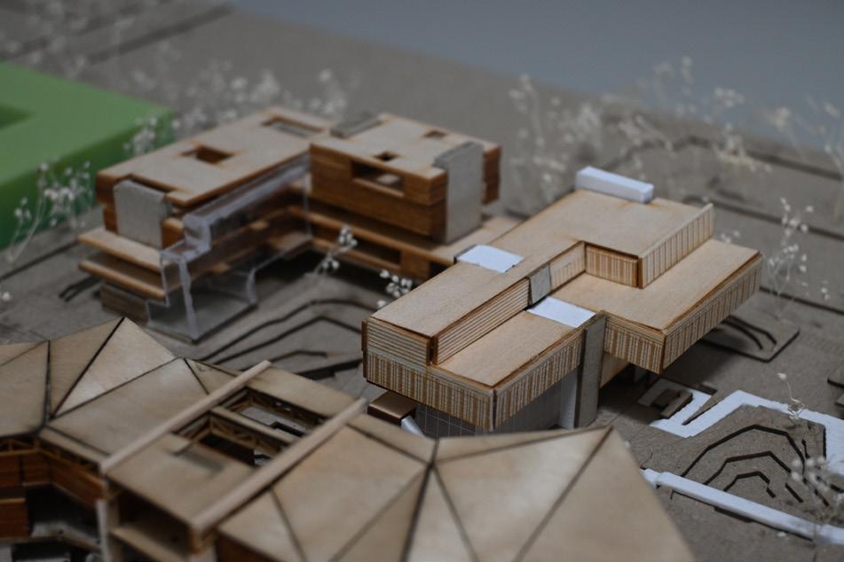
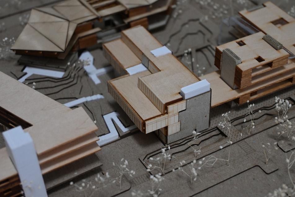
EXTERIOR VIEW PHYSICAL MODEL
342