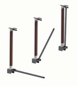
ES 17.5-800 kV Earthing switches


Ourrangeofdisconnectorsand earthingswitchesisdesignedto ensurethebestperformancesand reliability,whicharetheresultofour 70-year-oldexperience.
Over100,000disconnectors,withand withoutintegratedearthingswitches, installedinmorethan100countries worldwidearetheguaranteeofbestbuys.


ES are “Class E0” (ref. to IEC 62271-102) earthing switches, suitable for the installation both combined with disconnectors and as “stand-alone” equipment.
The “stand-alone” type is described in this brochure, but all construction features and ratings are also valid (with the obvious differences) for earthing switches combined with disconnectors.
According to their ratings, the ES can be supplied in the following types:
- “Single-motion” ( or “direct entry”)
- “Double-motion”
Both types are composed of three-poles, operated simultaneously either by a single operating mechanism and mechanical linkages between the poles, or by one mechanism for each pole.
To adapt to various layout of substations, earthing switches the poles can be erected traditionally (horizontally) or wall-mounted, and even upside down.
Like all our products, ES earthing switches meet the latest international standards (IEC, ANSI) and they can also be customised according to clients' particular specifications.
Upon request, special earthing switches can be designed and supplied to satisfy any particular need.
Examples of special earthing switches are:
- “Transformer neutral earthing switches”, provided with insulated base-frame and linkages, to allow the direct connection to earth of the neutral terminal of power transformers, without involving supporting structures and operating shafts;
- “Semi-pantograph earthing switches”, the ideal solution when post insulators are very high, which is quite common in EHVDC installations;
- “Valve hall earthing switches”, highly custom-tailored, to solve any issue related to the specific layout of HVDC valve halls.
Each pole consists of a moving arm and a fixed contact.
The moving arm is made of an aluminium alloy tube (for the lower ratings only, the arm is made of hot-dip galvanised steel) with a copper flat bar bolted at its end, suitably shaped for its correct engagement with the fixed contact; the moving arm is supported and hinged at the other end and it is electrically connected to the base-frame by means of flexible tinned copper braids (in special cases, aluminium straps are provided instead of copper braids).
The fixed contact consists of an aluminium alloy support, with copper fingers bolted to it; the number and dimensions of fingers depend on the rated short-time withstand current. Contact pressure, which is assured by stainless steel springs, is low under normal circuit conditions but, in case of short circuit, it increases rapidly, thanks to the finger reverse-loop design: this guarantees both low operating efforts and very high short-time withstand currents.
The support of the fixed contact, which is bolted to the top flange of a post insulator, also includes the HV terminal.
The post insulator, when supplied, ensures a good withstand to terminal loads and complies with either IEC or ANSI standards; special heights and creepage distances are also available upon request.
The base-frame of each pole is made of hot-dip galvanised steel and supports the post insulator, the moving arm and the mechanism that allows the rotation of the arm around an horizontal shaft; each baseframe is provided with suitable earthing terminals for the connection to the earthing system of the substation (customised terminal are available upon request).
The transmission system consists of a set of shafts, rods and levers, made of hot-dip galvanised steel and suitably linked to each other to transmit the power from the operating mechanism to the moving arms.
When integrated in disconnectors, the earthing switch (one or two per pole), is electrically and/or mechanically interlocked with the main switch.
The whole design and manufacturing process are ruled by ISO 9001 certified procedures, to guarantee a perfect reproducibility of performances from type-testing to series production.
The base-frame supports one post insulator B and the moving arm C, whose horizontal shaft D is directly linked to the transmission system.
In open position, the moving arm is perpendicular to the post insulator.
The rotation of the horizontal shaft makes the arm rotate for about 90°, until the moving contact E (male) gets in touch with the fixed one F (female), which is bolted to the top of the post insulator; then:
- for the “single-motion” type, the moving contact enter the fixed one directly, until the fully closed position is reached;
- for the “double-motion” type, the moving contact starts a vertical movement (along the axis of the arm), which makes it enter the fixed one.
When necessary for a smooth and low power-demanding motion, the weight of the moving arm is balanced by a spring.
The HV terminal G is as shown in the next page figure; customised terminal is also available upon request.


TE: To Earth
Rated short-time withstand current Ik (kA)up to 80 / 1-3s (depending on rated voltage)
Rated peak withstand current I
Due to lifetime greased or self-lubricated hinges and to self-wiping contacts, the maintenance of ES metallic parts is ensured by their own motion.
The use of corrosion-free (or coated) materials for all components ensures an exceptional reliability over many years of service.
The mechanical endurance performance exceeds the IEC standard requirements.
Upon request, earthing switches can be equipped with an induced current switching device, compliant with IEC 62271-102; for the highest ratings of induced current to be switched (or upon request) it can be of the “arc-free” type.
For operation under severe ice conditions (up to 20 mm), ice shields are available for protection of the equipment (where needed).