35 minute read
Installing copper pipework


but for pressure calculations a stress value the length of the tube at the lower temperature, irrespective of temper or wall thickness. (Coefficient of
appropriate to the particular temperature should be used, see Table 5.
Table 5 Stress values for working temperatures in excess of 65°C
Temperature
°C Max. admissable stress for annealed, R220,
110 150 175 200
4034 26 18
2.8 Thermal expansion
Table 6 shows the increase in length due to thermal expansion as a function of change in temperature ∆t and condition, N/mm 2
linear expansion 16.8 x 10 -6 per °C).
Table 6 Thermal expansion (mm) of copper tube as a function of tube length and temperature difference.
Tube length, Temperature difference
∆ t °C
m
∆ t = 30° ∆ t =40° ∆ t=50° ∆ t =60° ∆ t =70° ∆ t =80° ∆ t =90° ∆ t =100°
0.1 0.05 0.07 0.08 0.10 0.12 0.13 0.15 0.17 0.2 0.10 0.13 0.17 0.20 0.24 0.27 0.30 0.34 0.3 0.15 0.20 0.25 0.30 0.35 0.40 0.45 0.50 0.4 0.20 0.27 0.34 0.40 0.47 0.54 0.60 0.67 0.5 0.25 0.34 0.42 0.50 0.59 0.67 0.76 0.84 0.6 0.30 0.40 0.50 0.60 0.71 0.81 0.91 1.01 0.7 0.35 0.47 0.59 0.71 0.82 0.94 1.06 1.18 0.8 0.40 0.54 0.67 0.81 0.94 1.08 1.21 1.34 0.9 0.45 0.60 0.76 0.91 1.06 1.21 1.36 1.51 1.0 0.50 0.67 0.84 1.01 1.18 1.34 1.51 1.68 2.0 1.01 1.34 1.68 2.02 2.35 2.69 3.02 3.36 3.0 1.51 2.02 2.52 3.02 3.53 4.03 4.54 5.04 4.0 2.02 2.69 3.36 4.03 4.70 5.40 6.05 6.72 5.0 2.52 3.36 4.20 5.04 5.88 6.72 7.56 8.40 10.0 5.04 6.72 8.40 10.08 11.76 13.44 15.12 16.80 15.0 7.56 10.08 12.60 15.12 17.64 20.16 22.68 25.20 20.0 10.08 13.44 16.80 20.16 23.52 26.88 30.24 33.60 25.0 12.60 16.80 21.00 25.20 29.40 33.60 37.80 42.00
3 General requirements for the use of copper tube
3.1 The various uses
Copper tubes are generally used in buildings for the following services:
Domestic hot and cold water supplies under pressure, usually up to mains pressure (typically 60 psi or 4 bar or maybe up to 10 bar) or head pressure from a storage tank
Sanitary waste water drainage
Wet central heating systems (with radiators/ convectors)
Underfloor heating
Gas services for heating and cooking Copper tubes and fittings are also suitable and widely used for the following services:
Chilled water and refrigeration
Fire sprinkler systems
Air conditioning
Steam
Medical gases
Pneumatics
Hydraulics
Waste water
Expansion/contraction phenomenon due to temperature variation
Chemical attack due to external materials or the characteristics of internal fluids
Stresses imposed on the tubes during installation (or manufacture)
It is therefore important to know details of the environment to which the pipework will be exposed and also the stresses to which it will be subjected in order to assess the behaviour of the tubes.
3.2 Contact with other metals
Whenever two dissimilar metals are in contact, in an electrolyte containing dissolved oxygen, the assembly constitutes a galvanic (corrosion) cell in which the more noble metal is the cathode and the less noble metal is the anode, which tends to dissolve (corrode). A consequence of this is that the more noble metal is cathodically protected by the less noble (base) metal. For example galvanised (i.e. zinc coated) steel is protected by the preferential corrosion of the zinc coating and does not show significant rusting until the dissolution of the zinc coating is virtually complete.
With the exception of iron and steel components upstream of copper, when no undue corrosion will be experienced, in pipework carrying fresh water, the jointing of copper to iron or steel should be avoided as far as is possible, otherwise the iron or steel component will corrode preferentially. The corrosion of steel tanks commonly connected to copper pipes is reduced by the insertion of electrically insulating washers and also by the relative size of the exposed surfaces, in this case a large anode and a small cathode. A steel pipe attached to a copper tank or cylinder will corrode at a significantly greater rate since the relationship is one of large cathode and small anode. Similarly, iron or steel should not be installed downstream of copper in a fresh water circuit otherwise rapid corrosion of the iron or steel will occur. The conductivity of the water (electrolyte) also influences the rate of corrosion in that the higher the conductivity of the water, the greater will be the rate of any corrosion.
It should be stressed that galvanic corrosion does not occur in the absence of an electrolyte i.e. in a dry environment, so that the use of steel clips on a copper pipe will cause no problem. The steel clips may corrode preferentially, however, if the environment is prone to condensation e.g. a cold water pipe in a steamy (humid) atmosphere such as a kitchen.
The presence of dissolved oxygen in the water is a fundamental factor in galvanic corrosion within systems. In the primary circuit of an indirect heating system where the water continuously circulates for example, the oxygen is quickly used up in superficial corrosion of the ferrous components and galvanic corrosion is minimal. In a direct hot water system or where there is significant ingress of oxygenated water (e.g. due to over-pumping or leakage) ferrous components, such as steel radiators may fail quite rapidly. Whilst steel radiators may fail due to other factors, such as excess flux residues from soldered joints being washed in, over 90% of all steel radiator failures are due to the ingress of oxygen into the primary system. A typical galvanic series is given in Table 7.
Table 7 Galvanic series of metals and alloys
Corroded end: anodic – least noble
Zinc 99% aluminium Aluminium-copper alloys Steel or iron Cast iron Chrome-iron (active) Stainless steel (active) Lead-tin solders Lead Tin Brasses Copper Bronzes Copper-nickel alloys Silver solder Chrome-iron (passive) 18/8 Mo chromium-nickel austenitic steel (passive) Silver Graphite
Protected end: cathodic – most noble
In practice galvanic corrosion is not a serious problem unless the potential difference is greater than about 200mV, (the
1 / 4 volt criterion).
3.3 Contact with other materials
Copper is highly resistant to corrosion by most traditional building materials such as brick, plaster or concrete based on Portland cement. However, it should not be allowed to come into contact with acid plasters, acid cements or coke breeze.
Except for underfloor heating systems the installation of copper tubes or fittings within solid walls or floors is not recommended, unless they can be readily exposed, or alternatively if installed in a sleeve or duct where they may be readily removed or replaced. Any tubes passing through solid walls (by the shortest route) must be sleeved. Unprotected copper pipes should not be laid in screeds containing ammoniacal foaming agents nor allowed to come into contact with cleaning fluids, which may contain ammonia or its derivatives.
Copper also has high corrosion resistance to attack by soils, but again there are well known conditions that are aggressive to all metals, even to copper. These include “made-up” ground containing wet ashes or clinker, poorly drained sites with a high chloride or sulphate content or wet
soils containing decaying vegetable matter or nitrogenous fertilisers. Furthermore, the laying of underground services in contact with contaminating materials such as foul soils, or passing through any sewer, drain or cesspit is prohibited. Underground services should be installed using thick walled copper tube, (formerly designated Table Y) and all the fittings should be immune or resistant to dezincification. Any compression fittings should be of the manipulative type to BS EN 1254: Part 2, Type B.
Unless the building materials or soils are known to be nonaggressive to copper, it is advisable to use factory supplied plastics coated copper tube or to protect the tubes and fittings by means of a suitable waterproof wrapping.
3.4 Behaviour of copper tubes in contact with different fluids 3.4.1 Drinking water
Copper is highly corrosion resistant to potable water which complies with “EC Directive relating to the Quality of Water intended for Human Consumption” and World Health Organisation “International Standards for Drinking Water” and provided according to the Water Act of 1989.
In some areas where the water is particularly “soft” and may tend occasionally toward the acid side of neutral, new installations of copper tubing may give rise to the staining of sanitary ware and copper pick-up, resulting in a slightly metallic, astringent taste to the water. As mentioned later in 3.5, copper is not a toxic metal under these circumstances and the taste problems can be avoided by running the tap for a few minutes to clear the pipes. The condition will slowly improve as protective films build up on the inside surface of the tubes. In some waters this may take weeks or even a few months, but if it persists longer than this, expert advice should be sought with a view to increasing the hardness of the water supply concerned.
Some years ago, corrosion problems were encountered in hard, organically pure cold water supplies, invariably deep well or bore-hole derived, due to residues of carbon produced on the inside surface of tubes during manufacture. Many years of research and development in the UK have ensured that “Kitemarked” tubing is free from carbon films.
3.4.2 Softened water
Hard waters may be softened to avoid excessive deposits of scale in boilers and hot water services by replacing insoluble calcium and magnesium salts with soluble sodium salts. However, softening should be carried out with care since the softened water is almost always more aggressive than the raw water concerned. Since there is no virtue in softening the cold water, indeed the softening of water to kitchen and drinking water taps is prohibited, only cold supplies to hot services should be softened and then only to a minimum total hardness of 60 ppm. as CaCO 3 , by means of a valved by-pass system.
3.4.3 Deionised water
Deionised water is equivalent to distilled water, both anions and cations having been removed by ion exchange resins. It is to some extent aggressive to all but the exotic metals e.g. gold, platinum etc., and if required as pure water it should be conveyed in glass or other suitable materials.
If it is used as a heat transfer fluid, e.g. in air conditioning equipment, an appropriate inhibitor, such as benzotriazole should be added and the inhibitor level checked periodically to avoid corrosion.
3.4.4 Hydrazine and nitrites
Hydrazines or nitrites are sometimes added to heating installations as corrosion inhibitors in mixed metal systems to avoid galvanic corrosion. Both may be converted to ammoniacal species, by breakdown or reduction, which can give rise to the corrosion of copper or its alloys (e.g. brass). When corrosion occurs the concentration of the inhibitor is often reduced, but this is precisely the wrong action, since ammonia is not aggressive to copper in the absence of oxygen and since hydrazine and nitrites are oxygen scavengers, their concentration should be increased to between 4 and 7 times the value of the dissolved oxygen content (in ppm.).
3.4.5 Household products
There are several household products currently available that can attack copper, such as ammonia solutions and hypochlorite bleaches. Cleansers containing ammonia should not be allowed to come into contact with copper otherwise the copper tubing will blacken, or even show evidence of bright blue cuproammonium salts. Copper is not unduly susceptible to stress corrosion cracking. However, when in contact with these chemicals there is a risk of cracking in tubes that contain residual tensile stresses. Clearly hard and half-hard tubing is at greater risk than annealed tubing, but any brass compression fittings offer the greatest risk, especially any compression nuts that have been over-tightened. This applies particularly when cleaning floors in kitchens etc., where pipes are buried beneath the floor.
Cleansers containing hypochlorites should be used with care, for whilst hypochlorite solutions are excellent sterilising agents and widely used for this purpose, the strength of solution and exposure times need to be carefully controlled. To avoid any risk of attack, the strength of solution should be limited to 50 ppm free chlorine for a period of no more than 1 hour, (BS 6700). Sterilising solutions should not be left in systems overnight and when the process is complete, the system should be washed through with fresh water until the residual free chlorine level is down to 1-2 ppm. Similarly, the practice of leaving such cleaners in urinals and waste pipes overnight should be discouraged. Specifically designed toilet cleansers however based on “nitre cake” (sodium hydrogen sulphate) do not attack copper.
3.4.6 Various chemical products
Copper tubes are widely used in industry and they may come into contact with many different chemicals that are not commonly found in the domestic situation. Table 8 gives general information on the suitability of copper with various chemicals.
Acetic (Acid) B Chromic Acid D Oxalic Acid C Acetic (Anhydride) B Cider A Oxygen** A Acetone A Citric Acid C Oxygenated water B Acetylene (see note 1) D Coffee A Palmitic Acid* B Alcohols A Copper Chloride C Paraffin Wax A Alum B Copper Nitrate C Phosphoric Acid C Alumina A Copper Sulphate B Potash B Aluminium Chloride B Corn Oil* A Potassium Carbonate B Aluminium Hydroxide A Cottonseed Oil* A Potassium Chloride B Aluminium Sulphate B Creosote A Potassium Chromate B Ammonia Gas (Dry) A Crude Oil (Low Sulphur) A Potassium Cyanide D Ammonia Gas (Wet) D Drinking Water A Potassium Sulphate A Ammonium Hydroxide D Ethers A Propane A Ammonium Chloride D Ethyl Acetate A Rosin A Ammonium Nitrate D Ethyl Chloride B Seawater C Ammonium Sulphate D Ethylene Glycol (Inhibited) A Silver Salts D Amyl Acetate A Ethyl Alcohol A Soaps (Solutions of) B Amyl Alcohol A Ferric Chloride D Sodium Bicarbonate B Aniline D Ferric Sulphate D Sodium Bisulphate B Aniline (Dyes) C Ferrous Chloride C Sodium Bisulphite B Asphalt (Dry) A Ferrous Sulphate C Sodium Carbonate B Atmosphere (Industrial) A/B Fluorosilicic Acid C Sodium Chloride B Atmosphere (Marine) C Formaldehyde B Sodium Chromate B Atmosphere (Rural) A Formic Acid B Sodium Cyanide D Barium Carbonate A Freon A Sodium Hypochlorite C Barium Chloride B Fruit Juice B Sodium Nitrate B Barium Hydroxide A Fuel Oil A Sodium Peroxide C Barium Sulphate A Furfural B Sodium Phosphate B Barium Sulphide C Gasoline A Sodium Silicate A Benzene A Gelatine A Sodium Sulphate A Benzine A Glucose A Sodium Sulphide C Benzoic Acid D Glue B Sodium Hyposulphite D Beer A Glycerine A Solvents for Varnish A Bordeaux Mixture A Hydrobromic Acid D Steam A Borax A Hydrocarbons (Pure) A Stearic Acid* B Boric Acid A Hydrochloric Acid D Sugarbeet (Syrup) A Brine C Hydrocyanic Acid D Sulphur (Dry) B Bromine (Dry) A Hydrofluoric Acid D Sulphur (Molten) D Bromine (Wet) C Hydrogen A Sulphur Chloride (Dry) A Butane A Hydrogen Sulphide (Dry) A Sulphurous Anhydride (Dry) A Butyl Alcohol A Hydrogen Sulphide (Wet) D Sulphurous Anhydride (Wet) B Butyric Acid B Kerosene A Sulphuric Anhydride (Dry) A Calcium Chloride C Lacquers A Sulphuric Acid (80/95%) D Calcium Disulphide B Lactic Acid B Sulphuric Acid (40/80%) D Calcium Hydroxide A Lime A Sulphuric Acid (<40%) C Calcium Hypochlorite C Linseed Oil* B Sulphurous Acid C Cane Sugar Syrup A Magnesia A Tannic Acid B Carbolic Acid C Magnesium Chloride B Tar (Dry) A Carbon Tetrachloride (Dry) A Magnesium Sulphate A Tartaric Acid C Carbon Tetrachloride (Wet) B Mercury (and its salts) D Toluene A Carbon Dioxide (Dry Gas) A Methyl Chloride (Dry) A Trichloroacetic Acid C Carbon Dioxide (Wet Gas) D Methyl Alcohol A Trichloroethylene (Dry) A Castor Oil A Milk* A Trichloroethylene (Wet) B Caustic Soda B Mine Water (Acid) C Turpentine A Chlorine (Dry) A Natural Gas A Varnish A Chlorine (Wet) D Nitric Acid D Vinegar C Chloroacetic Acid C Nitrogen A Zinc Chloride C Chloroform A Oleic Acid C Zinc Sulphate C
A = Resistant to corrosion B = Resists corrosion well C = Undergoes slow corrosion D = Copper is not to be recommended in the presence of the substance considered Note 1: Copper alloys containing more than 70% copper cannot be used for handling acetylene.
3.5 Action of copper on drinking water
As mentioned previously in 3.4.1, copper is entirely suitable for use with potable water as defined by EU regulations and WHO guidelines. These also specify that the copper content of the water does not exceed 2 mg/l.
Copper is often erroneously considered a toxic metal,
4 Working with copper tube
4.1 Cutting
Small diameter pipes, up to 12 mm OD are best cut with a junior hacksaw but it is usually more convenient to use a tube cutter for 15, 22, 28 and 35 mm sizes. Alternatively, and for larger size pipes, a fine toothed hacksaw (32 teeth per inch) can be used. Where many lengths are to be cut power hacksaws, circular saws (with a fine, metal cutting blade) or abrasive cutting discs may be used. Whatever method is used, the tools must be sharp and in good condition to avoid distortion of the tube end. All ends must be cut square and both internal and external burrs carefully removed using a file or reamer. When using a tube-cutter care must be taken to avoid distortion (“nozzling”) which can not only induce turbulence and/or restrict water flow, but also reduce the strength of a capillary joint. If necessary tube ends should be re-rounded using a suitable tool and in the case of coils in the annealed condition, re-rounding should always be carried out, to avoid any ovality which could adversely affect the strength of the capillary joint.
4.2 Annealing
It is sometimes necessary to anneal half-hard tube in the larger sizes, to facilitate specialist bending or forming. To achieve this, the tube is heated to a dull red heat (600°C) and is either allowed to air cool or may be quenched immediately in cold water. Care should be taken not to exceed the annealing temperature (600°C) as this could give rise to grain growth (the so-called “orange peel” effect) which can significantly adversely affect the properties, including ductility, of the tubing.
4.3 Bending 4.3.1 Annealed, R220, and half-hard, R250, tubes
Copper tubes in the annealed or half-hard condition are easily bent by using bending techniques appropriate to the size and temper of the tubes.
Suitable flexible bending springs, used either externally or internally as appropriate, manufactured in accordance with BS 5431 are available for standard size straight tubes from 10 to 22 mm. Only relatively easy bends, over the knee or a suitable former should be attempted and to a minimum radius of 5 times the diameter of the tube to the inside of the bend (root radius). rather, it is a desirable “trace element”, the human body requiring about 2.5 to 5 mg/day to maintain normal health. Lead, on the other hand, which was widely used for plumbing services in the last century and the beginning of the present century, and may still be present in older installations, is known to be particularly toxic.
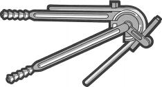
Figure 1 Hand bender
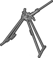
Figure 2 Bending machine
Portable bending machines, suitable for bending tubes up to and including 54 mm OD are readily available, indeed some smaller benders, up to 22 mm can be carried in a tool kit. For tube sizes larger than 54 mm, fixed power benders are the only satisfactory option.
All bending machines work on the principle that the tubing is bent between matched formers and back guides, which support the OD of the tubing, thus eliminating the risk of collapse of the tube wall. However, the point at which the bending pressure is exerted on the tube is critical. This point must be
maintained at an optimum distance in front of the point of support on the former, but if this distance is too small excessive throating of the bend will occur or if it is too great, corrugations will appear in the inner radius of the bend and flattening of the outside of the bend will occur. On a correctly set up bending machine the lever arm will be at right angles to the tube that is to be bent. It is recommended therefore that adjustable bending machines are used, since these permit the pressure on the back guide to be adjusted and so accommodate machine wear to form perfect bends every time.
Severe corrugations or flattened bends can adversely affect flow conditions in service, potentially giving rise to localised impingement (corrosion erosion) or, in hot services, to fatigue cracking resulting from stresses set up by thermal movement being concentrated at the corrugations, (a “notch” effect) whereas a smooth bend will absorb such stresses without damage.
The radius of bends formed on machines will naturally depend on the dimensions of the former supplied. Where particularly tight bends and/or full bore bends to the original OD throughout the bend are required, a more sophisticated machine using a mandrel to support the tube internally is recommended. Such machines
5Jointing of copper tubes
5.1 Ease of assembly
In addition to the corrosion resistance of copper and its physical properties, which allow it to be manipulated easily, possibly the greatest single advantage in installing copper tube is the ease with which it can be joined. The fittings, which are available world wide and in a wide variety include straight connectors, elbows and tees thus enabling even complex installations to be carried out easily and quickly, thereby greatly reducing installation costs.
5.2 Types of fitting
Fittings fall into two main categories, capillary and compression types, with a new third category of push-fit and press-fit fittings.
5.3 Capillary fittings 5.3.1 Use of capillary fittings
The capillary fitting utilises the force of capillary action to ensure that molten solder, or brazing alloy, is drawn into the gap between the outside surface of the tube and the inside surface of the socket of the fitting to produce a very strong joint. The strength of the joint, when correctly made, is invariably stronger than the tube. Indeed in tensile and pressure tests to destruction the tube invariably breaks before the joint. The practice of sand loading and/or hot bending of tubes is now redundant, since it is more convenient and satisfactory to bend cold by one of the methods given above.
It should be noted that bending tubes greater than 54mm diameter and forming tight radius bends (i.e. with inside radius less than 3 times the tube diameter) are generally considered to be specialist operations and reference should be made to equipment and product manufacturers.
4.3.2. Tube bending guide Table 9 Tube bending guide
Outside Minimum Method of Diameter (mm) bending radius* bending
<10 3 times the OD External spring Bending machine >10, <22 3 times the OD Internal spring Bending machine >22 3 times OD Bending machine *Bending radius is the root radius, i.e. tube bend inside radius. Hard drawn tube greater than 18mm diameter is generally not suitable for bending. Spring bending of coils is not recommended.
provided by the dimensional requirements of BS EN 1057 for tubes and BS EN 1254 for fittings.
There are two types of capillary fitting, one contains an integral solder ring in each socket of the fitting, whilst the second, the end-feed type, requires solder or braze filler to be applied to the mouth of the socket when the assembly has been heated to soldering temperature.
Figure 3 Capillary fittings
Whilst an integral solder ring fitting is usually more expensive than an end-feed type, it is easier and quicker
to install and because no extra solder is required, the installed costs of the two types of fittings are similar. Indeed the only real advantage of the end-feed fitting is that a different type of solder or a brazing alloy such as copper (silver) phosphorus, may be used in special circumstances. A further advantage of ISR is that the solder is guaranteed lead free.
5.3.2 Jointing without fittings
Copper tubes can be joined without using a fitting by expanding the end of one tube to form a socket and inserting the end of another tube of the same diameter. This is achieved by using a precision expander, which forms a socket of similar internal dimensions to the socket of a fitting made to BS EN 1254 and the joint is made in precisely the same manner as an end-feed fitting. The economics of this type of joint are clearly dependent on the skill and labour costs of the operative.
Socket forming for equal diameter tubes Connections of tubes with different diameters
Expander
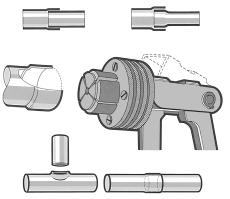
Socket joint Branched joint
Figure 4 Jointing without fittings
Branches may also be formed by drilling through the tube wall and opening it out to form a socket to which another tube is brazed. However, without specific equipment this process is relatively time consuming and requires the specialist skills of a copper-smith, generally beyond the scope of the average plumber and is consequently only used in special circumstances.
5.3.3 Soft soldering
Whether an integral solder ring or end-feed type of capillary fitting is used, the method of preparing the tube and fitting is the same. The tube end must be cut square and deburred both internally and externally. The outside surface of the tube end, to the depth of the socket, and the inside surface of the socket in the fitting are abraded with a cleaning pad and the outside of the tube smeared with a thin film of flux, preferably using a small brush, not a finger.
The tube end is then inserted into the socket, with a slight twisting motion to spread the flux evenly and any excess flux is wiped from the mouth of the socket. With an integral solder ring fitting, the joint is then heated with a propane or butane/air blow lamp, or for larger size pipework an air/acetylene or oxy/acetylene torch, until a complete ring of molten solder appears around the mouth of the socket. At this point the heat source is removed and the joint is allowed to cool without disturbance until the solder re-solidifies.
With an end-feed fitting, the joint is heated to the melting point of the solder and the heat source removed. On applying the solder rod or wire to the mouth of the fitting the solder should melt on contact with the tube and fill the capillary gap until a complete solder ring appears. The joint is then left to cool without disturbance.
Several types of solder and brazing alloy are available, depending on the service required.
In order to ensure that joints in potable water services cannot contaminate the water with lead, tin/copper or tin/silver solders, with melting points of about 230 to 240°C, must be used. Tin/lead solders, with a melting point of about 220°C, could be used for gas or central heating services, but it is recommended that only leadfree solders are used throughout an installation in order to avoid any risk of inadvertent mixing of solders.
For low temperature services e.g. chillers or refrigeration circuits, tin/silver solders are recommended, whilst for any joints in underfloor heating circuits, copper-silverphosphorus brazing alloys are recommended.
The integrity and strength of capillary joints are greatly dependent on the uniformity of the capillary gap and therefore not only must the tubes and fittings be compatible, but also the tube ends must be free from significant deformation and ovality. It is therefore good practice to re-round tube ends after cutting and de-burring, even on half-hard and hard drawn tubes, if any distortion is apparent. On annealed, coiled, tubing where ovality and distortion are almost inevitable, re-rounding after deburring is of vital importance.
For soft solders there are several different types of flux, the purpose of the flux is to chemically clean the metal surface and also prevent re-oxidation of the surface during heating to enable the solder to run and “wet” the surfaces to be joined. Ideally a flux should only be aggressive to the metal concerned at soldering temperatures, but this is difficult to achieve in practice.
Fluxes containing organic chlorides, bromides or zinc and/or ammonium chlorides, emulsified in a grease base, such as petroleum gel, are those most commonly used in plumbing. They are all to some extent corrosive to copper, otherwise they would not clean the metal surfaces, and therefore must be used sparingly and any excess removed when soldering is completed. They
should be spread as a thin film, preferably using a small brush, over the cleaned tube surface, taking care not to allow flux to creep into the bore. When a section of pipework has been completed, it should be flushed out with water to remove any excess flux residues.
The so called “self-cleaning” fluxes contain free hydrochloric acid and whilst they are excellent fluxes they should be used with extreme care, in accordance with the manufacturers instructions and any excess removed after jointing.
5.3.4 Hard soldering
For installations that operate at higher temperatures or pressures than can be tolerated by soft soldered fittings e.g. steam services, or where grease-based fluxes are prohibited e.g. oxygen lines, a range of high-duty fittings is available. High-duty fittings usually contain integral rings of silver brazing alloy, though end-feed types are also available. Only the fluxless brazing alloys are allowed for oxygen lines.
The silver brazing alloy used melts at a temperature greater than 650°C (cherry-red heat), requiring the use of an oxy/acetylene, oxy/propane or acetylene/air torch and since this is above the annealing temperature of copper all pressure calculations must be based on the stress value for the annealed, R220, condition. A special borax-based flux is used.
Copper-silver-phosphorus filler metals, (which should not be used on ferrous metals, nickel based alloys or copper alloys containing nickel), are used in much the same way as soft solders, except that their melting points are higher (645 to 800°C). No flux is required however, since the phosphorus content of the alloy is an effective de-oxidiser. These are preferred for medical and oxygen gas lines.
5.4. Brazing and welding
Copper tubes may also be joined by brazing or autogenous welding, using suitable alloy filler rods, but such methods are not normally applicable to construction sites.
It should be noted that the composition of the filler rods must be carefully selected to avoid any risk of preferential corrosion or de-alloying of the joint fillet, such as dezincification.
Care must also be taken to avoid prolonged overheating during jointing, since this could lead to grain growth, or even localised melting with the melting point of some of the brazing alloys being above 800°C.
5.5 Compression fittings
Compression fittings are available in two types, each type being primarily designed for specific usage. Type “A” non-manipulative compression fittings, manufactured to BS EN 1254 Part 2 Type “A”, as the name implies, do not require any manipulation of the tube end prior to installation. The joint is made by tightening a compression ring or sleeve onto the outside of the tube when the compression nut is tightened onto the body of the fitting. This type of fitting can be used on straight lengths of half-hard tubing but only up to 12 mm OD on coiled annealed tubing unless a suitable supporting sleeve is provided.
The fittings are approved for surface fixing or where readily accessible (in ducts etc.). Jointing is carried out very simply as follows:
1. Cut the tube end square using a tube-cutter.
2. Remove both internal and external burrs.
3. Re-round tube ends if necessary. (Always on annealed tube.)
4. Slip compression nut and then compression ring onto tube
5. Insert tube end into fitting up to the tube stop.
6. Tighten the compression nut finger tight and then fully tighten with an appropriate size spanner by the number of turns recommended by the fittings manufacturer.
Jointing paste should not be necessary, indeed it may interfere with the integrity of the metal to metal joint. Reference should be made to manufacturer’s recommendations.
Type “A”
Fitting body Compression ring
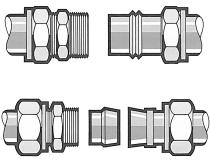
Compression nut
Type “B”
Fitting body Adaptor Compression Compression (gunmetal) ring nut (gunmetal)
Figure 5 Compression fittings
Type “B” manipulative compression fittings require the end of the tube to be flared, cupped or belled with a special forming tool (in some cases supplied by the fittings manufacturer) after the end of the tube has been cut square. The formed end of the tube is compressed against a corresponding section of the fitting, or against a loose thimble, when the correspondingly shaped compression nut is tightened.
Manipulative compression fittings are not suitable for use with hard tubes and annealed tubes must be carefully deburred and re-rounded before the tube end is formed. This type of fitting, to BS EN 1254: Part 2 Type “B”, must be used for underground installation and therefore must be made from dezincification resistant or immune materials.
5.6 Push-fit Fittings
Push-fit fittings are new, reliable and versatile. As the tube is inserted into the fitting in several types it passes through a release collar and then a stainless steel grab ring. The grab ring has a series of teeth that open out and grip onto the outside of the copper tube. A support sleeve inside the fitting will help in alignment of the tube and when the tube is fully inserted, to the tube stop, an ‘O’ ring is compressed between the wall of the fitting and the tube. For a secure joint to be formed the tube must pass through the ‘O’ ring and reach the tube stop. In some push-fit fittings the position of the ‘O’ ring and grab ring are reversed.
Most of these fittings can be disconnected, and the operation is as simple as forming the joint. Pressure is
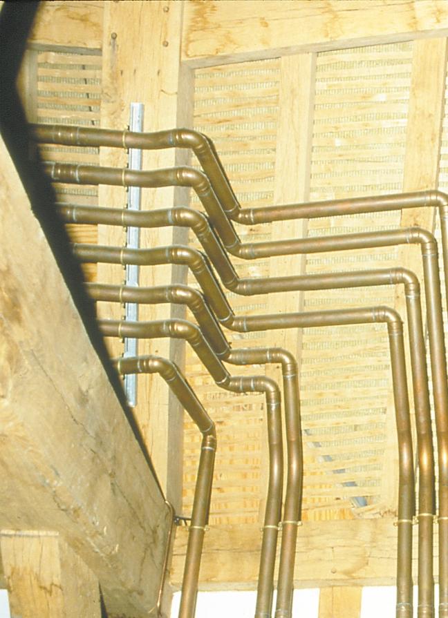
6 Installing copper pipework
The general specification for the design, installation, testing and maintenance of services supplying water for domestic use within buildings and their curtilages is BS 6700.
6.1 General requirements
To ensure long and trouble-free service life, copper tubes and fittings should be installed with due care in a proper workmanlike manner. Circuits should be designed to operate at optimum flow conditions, i.e. for cold water circuits between 0.5 and 3 metres per second and for hot water recirculating systems between 0.5 and 1.5 metres per second. They should be arranged in such a manner that “dead-legs” are kept to an absolute minimum. Joints should be made carefully to avoid excess flux residues both from entering the system and contaminating the exterior. Each section of a large circuit should be flushed through after completion to remove flux and debris.
In hot water services and central heating systems, tubes must be fixed in a manner that allows thermal movement, i.e. expansion and contraction without imposing undue stress on the tubes and fittings.
The more important specifications covering the use of copper tubes in buildings are detailed below:
BS EN 1057: Copper and copper alloys – Seamless, round copper tubes for water and gas in sanitary and heating applications. applied to the release collar in the mouth of the fitting, using a special disconnecting tool, which splays the teeth of the grab ring. Thus the tube is freed from the fitting. Other types require a securing cap to be unscrewed.
Push-fit fittings are suitable for all above ground hot and cold domestic water services, including both direct and indirect heating systems. They are also ideal for use in smallbore and microbore central heating systems and in pressurised unvented heating systems within the permitted temperature and pressure limits.
Press-fit fittings
Press-fit fittings are another new type of fitting requiring a special compression tool. The fitting is slid over the tube and mechanically crimped between the body of the fitting and the ‘O’ ring seal at the end of the fitting. The tube must be prepared as for a push-fit fitting in order to ensure the ‘O’ ring is not damaged. This type of joint is quick and effective requiring no spanners or flame but does require the special tool.
BS EN 1254: Copper and copper alloys – Plumbing fittings
Part 1: Fittings with ends for capillary soldering or capillary brazing to copper tubes.
Part 2: Fittings with compression ends for use with copper tubes.
Part 4: Fittings combining other end connections with capillary or compression ends.
BS 1306: 1975 (1983): Specification for copper and copper alloy pressure piping systems.
BS 5431: 1976 (1987): Specification for bending springs for use with copper tubes for water, gas and sanitation.
BS 6700: 1997: Specification for the design, installation, testing and maintenance of services supplying water for domestic use within buildings and their curtilages.
BS EN ISO 9002 Quality systems. Model for quality assurance in production, installation and servicing.
These are available from British Standards Institution.
Further detailed information is contained in CDA Publications:
33 – Copper Tube in Domestic Water Services.
6.2 Location of pipework and fittings
Copper pipework can be laid along walls and partitions, surface fixed or in purpose-made ducts, preferably with removable covers, to enable repair or maintenance work to be carried out. Similarly, pipework may be enclosed in ceilings where access is possible e.g. in suspended ceilings.
Except for underfloor heating, pipework in floors is only permitted in channels or ducts fitted with removable covers for repair, maintenance and inspection.
The installation of copper pipes in cesspits or refuse chutes is prohibited and is only allowed in flues, e.g. on connections to fire-back boilers, etc., if adequately protected from condensing flue gases, soot, etc.
Any joints between pipework and units which must be dismantled for maintenance should be installed with disconnecting fittings.
6.3 Fixings
All pipework should be adequately supported by clips, at suitable intervals as follows:
Table 10 Maximum interval for spacing of clips.
Size of Pipe (OD) mm
6.0 8.0 10.0 12.0 15.0 22.0 28.0 35.0 42.0 54.0 67.0 76.1 108.0 133.0 159.0
Intervals for Vertical Runs m
0.6 0.9 1.2 1.5 1.8 2.4 2.4 3.0 3.0 3.0 3.6 3.6 3.6 3.6 4.2
Intervals for Horizontal Runs m 0.4 0.6 0.8 1.0 1.2 1.8 1.8 2.4 2.4 2.7 3.0 3.0 3.0 3.0 3.6
6.4 Effects of expansion
As mentioned in section 2.8, the coefficient of linear expansion of copper is 16.8x10 -6 per °C and hence a 10m length of copper tube, irrespective of its size, wall thickness or temper, will increase in length by 10.08mm when heated through 60°C. Pipes installed on hot water services must be free to accommodate this expansion, otherwise stresses will build up in the pipework, which may lead to joints being pulled apart and/or tubes fracturing. Clearly the magnitude and frequency of such changes in length will determine the life of the joint or failure of the tube. heating installations the limited size of rooms and hence straight pipe runs, together with the many bends and offsets that normally occur will result in thermal movement being accommodated automatically. However where long straight pipe runs, exceeding 10m, are encountered, allowance for expansion should be made.
Expansion bellows and expansion loops may be accepted with regard to the expansion of pipes carrying hot water. Where copper tubes pass through walls, floors and ceilings, they should be able to move as a result of expansion and contraction. This can be arranged by passing the tube through a sleeve or length of larger diameter pipe fixed through the whole thickness of the wall, floor or ceiling, or by means of flexible joints on either side of the wall.
Short stubs to and from radiators, connected to relatively long straight runs should also be avoided. This can usually be achieved by introducing an expansion loop, thereby increasing the length of pipework fixed between the flow/return legs and the radiator connection. However, expansion accommodation techniques such as the use of loops and horseshoes may not be sufficient to accommodate large expansions and in such cases the use of expansion bellows or glad type expansion joints may be necessary.
By change of direction
‘Horseshoe’ or compensating bend
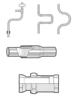
Bellows type expansion joint
Tightening nut Packing ‘Throw’
Compression ring Gland type expansion joint
6.5 Pipework in screed or passing through walls
Except where a pipe passes through a wall, where it must be enclosed in a sleeve and must take the shortest practical route, the embedding of pipework in the load bearing fabric of buildings is prohibited. Special arrangements are made for the rising main into a building. Except for underfloor heating, pipework is not permitted in a solid floor or screed unless a purpose made duct with a removable cover is provided. In the case of underfloor heating, where the temperature is below 60°C, the coefficient of expansion of copper is so close to that of concrete that no problems will be experienced if annealed copper tubes, free from joints within the screed, are laid in a serpentine fashion, where any expansion stresses on one leg are neutralised by the adjacent leg. All joints to the main feed and return must however be placed in accessible ducts. Many water suppliers will permit this type of installation, particularly if the tubes have a factory applied plastic coating, to avoid any risk of contamination through the screed by floor cleansers, etc., but approval should be sought from the water supplier concerned, before any installation work is carried out.
6.6 Plastics coated pipework
Factory applied plastics coated pipework is available to protect the tube from aggressive environments when buried or for aesthetic reasons. One variety of this pipework has channels running on the inside of the plastics coating to trap air and provide some insulation. When jointing this pipework or at any termination it is important to ensure that the exposed ends of the channels are covered with a self adhesive tape to prevent any moisture or aggressive materials from entering the channels and attacking the tube.
Copper Development Association Publication Number 88 First published March 1991 Revised August 2000.
Copper Development Association Verulam Industrial Estate 224 London Road St. Albans Herts AL1 1AQ Tel: 01727 731 200 Fax: 01727 731 216
E-mail: copperdev@compuserve.com Websites: www.cda.org.uk www.brass.org
