
43 minute read
TA1: Designing processes
The types of manufacturing processes see p.67
What you need to know
• The six types of manufacturing processes • How these processes change the form of materials • How to select appropriate processes to create a given product.
A range of processes can be selected when planning how to manufacture a component or product.

The six types of manufacturing process Wasting removes excess material as chips or swarf to produce individual component features
Finishing applies a coating on the surface of a component to improve appearance or resist corrosion Additive manufacturing adds material layer by layer to build up the required shape of a component
Remember it!
Use this mnemonic to help you remember the different manufacturing process types: JAWSFrightens Fish
Joining Additive manufacturing Wasting Shaping Forming Finishing
Joining Forming fi xes components together either permanently (for example, welding) or non-permanently (for example, applies force to bend or reshape material into the required form nuts and bolts)
Shaping melts and re-shapes material in a mould to produce a complete (or near complete) component Manufacturing processes Look at these images. Draw spider diagrams Revise it!DRAFT for each to help think about what processes could be used to make the products, and why you would choose these processes.


Wasting processes: Sawing see p.68
What you need to know
• The tools, equipment, steps and safety measures used when sawing.
Sawing is a wasting process that uses a thin, toothed blade to remove material and cut a narrow slit.
Types of saw Hand tools: Hacksaw, junior hacksaw, coping saw Power tools: Mechanical power hacksaw, band saw Safe use of saws Hand tool Use Safety Hacksaw Straight cuts in metal <30 mm thick Handle sharp tools with care. Junior hacksaw Straight cuts in metals and polymers <10 mm thick Do not apply excessive pressure when cutting, or blades might break. Store tools safely when not in use. Coping saw Complex curved shapes in wood or Beware of burrs and sharp edges that can cause cuts.polymer sheets <5 mm thick Power tool Use Safety Mechanical power hacksaw Straight cuts in metal >30 mm thick Use only when trained in the safe operation of the equipment. Band saw Straight or curved cuts in a wide Wear eye protection and substantial footwear. range of materials depending on Secure long hair and loose clothing, and remove the type of blade and cutting rings and jewellery. speed used Ensure workpieces are clamped and/or supported appropriately.
Hacksaws are used for cutting metals and polymer materials by hand DRAFT
Revise it! Remember it!

Imagine you need to cut a length of 10 mm × square bright mild steel bar. Which type of saw would you use and why? How would you change your approach if you were asked to cut a larger mild steel bar that was 100 mm × 100 mm square? • Use the right saw for the job (otherwise you might cause damage, breakage and injury). • Mark out your work and always saw to a line. • Only use power saws if you are trained to do so and comply with all safety requirements.

Wasting processes: Filing see p.68
What you need to know
• The tools, equipment, steps and safety measures used when fi ling.
Filing uses a wasting process to remove material from the surface of a metal component to refi ne its shape.
Types of fi le
Common shapes: Flat Half-round Round Common fi le sizes (length): 6", 8", 10", 12" Common fi le cuts (size of the teeth): Smooth cut (fi ne), second cut (medium), bastard (coarse)
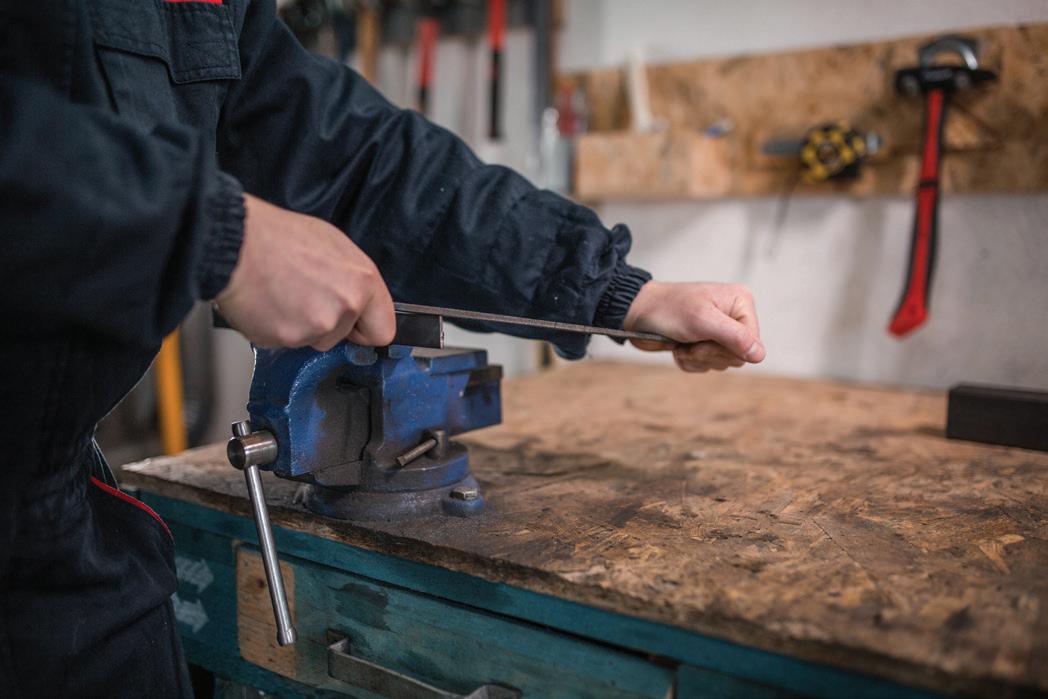
Using a fi le to remove material from a metal workpiece held in a bench vice. Remember it!Practise it! Safe use of fi les Shape Use Safety Flat fi le Flat surfaces and external curves Ensure fi le handles are secure before use (don’t use a fi le without a handle). Store tools safely when not in use. Beware of burrs and sharp edges that can cause cuts. Half round fi le Internal curves Round fi le Inside holes or tight internal curves Size: Use a fi le size appropriate to the size and shape of the workpiece. Cut: Use coarse cut fi les to remove material quickly. Change to a fi ner cut when near the required shape/size to give a good surface fi nish. Materials: Files can be use on non-ferrous and most ferrous metals as well as hard polymer materials.DRAFT
You have a large amount of steel to remove from the fl at edge of a workpiece that is 8 mm thick and 150 mm long.
Identify the type of fi le that would be most appropriate to use. (1 mark)
A 12" fl at bastard fi le
B 8" half round second cut fi le
C 12" fl at smooth cut fi le
D 6" round fi le • Choose the right shape, size and cut of fi le for the job. • Mark out your work and always fi le to a line.


Wasting processes: Shearing see p.68
What you need to know
• The tools, equipment, steps and safety measures used when shearing.
Shearing is used to cut metal sheet material using tools and equipment that employ a shearing action. The same principle is used when scissors cut through paper.
Types of shearing tools
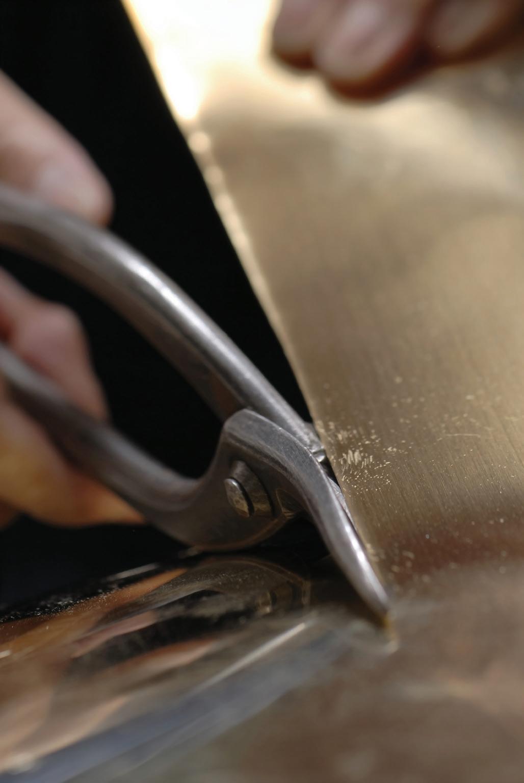
Hand tools: Tin snips (straight, right hand or left hand) Manually operated machinery: Foot operated manual guillotine The image shows a pair of tin snips being used to cut thin sheet metal. Safe use of shearing tools and equipment Tool Use Safety Tin snips (straight) Straight cuts in sheet metal (typically 0.8 mm maximum sheet thickness in mild steel) Use appropriate manual handling techniques when moving metal sheets. Beware of sharp points, burrs and sharp edges Tin snips that can cause cuts. (right hand) Wear eye protection and substantial footwear.
Right-handed curved cuts in sheet metal (typically 0.8 mm maximum sheet thickness) Tin snips (left hand)
Left-handed curved cuts in sheet metal (typically 0.8 mm maximum sheet thickness) Foot operated manual guillotine
Straight cuts in sheet metal (typically 1.6 mm maximum sheet thickness in mild steel) Allows long cuts to be made in a single action (typically 1300 mm maximum length)

Ensure all guards are in place prior to use. Use appropriate manual handling techniques when moving metal sheets. Beware of sharp points, burrs and sharp edges that can cause cuts. Use only when trained in the safe operation of the equipment. Wear eye protection and substantial footwear. Secure long hair and loose clothing, and remove rings and jewellery. DRAFT
Practise it! Remember it!

What would be the most appropriate way of making a 1200 mm straight cut in 0.6 mm thick mild steel sheet material? (1 mark) A tin snips (straight) B tin snips (right hand) C tin snips (left hand) D foot operated guillotine • Choose the right tool for the job. • Don’t exceed the maximum material thickness. • Wear gloves when handling metal sheets to protect you from burrs and sharp edges.

Wasting processes: Drilling see p.69
What you need to know
• The tools, equipment, steps and safety measures used when drilling.
Drilling is a very common machining operation used to produce round holes in a wide range of materials.
Types of drilling tools and equipment
Equipment: Pillar drill, portable cordless drill Tools: Twist drills (for holes up to 13 mm diameter), hole saws (for holes larger than 13 mm diameter in sheet material) Work holding devices: Vice, machine vice, clamps The image shows a pillar drill being used to drill a hole in a workpiece clamped in a machine vice. Safe use of drilling tools and equipment Equipment Use Safety Pillar drill Used in the workshop for drilling accurately positioned, vertical holes Speed set according to the workpiece material and size of the drilled hole There seem to be missing linking verbs in the text that affect readability. The original was: "Rotating parts <are> guarded Table <is> adjustable to support work and allow secure work holding (using machine vice or clamps). Rotating tool <is> lowered vertically into the workpiece Use only when trained in the safe operation of the equipment. Use appropriate speed according to the material and size of the drilled hole. Clamp the workpiece securely. Ensure all guards are in place prior to use. Wear eye protection and Portable substantial footwear. cordless Secure long hair and loose drill clothing, and remove rings and jewellery.
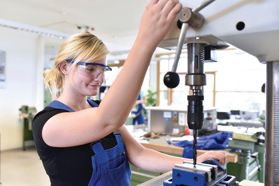
Portable hand-held machine used for general drilling operations Convenient and versatile No guards Single speed Low accuracy Remember it!Revise it!DRAFT Draw a spider diagram to summarise drilling. Include headings such as: safety, tools, work holding and equipment. • Where possible use a pillar drill as it’s the safer and more accurate option. • Use an appropriate speed according to the material and the size of the drilled hole. • Use a series of progressively larger drill bits when drilling a large hole (maximum 13 mm diameter). • Mark out your work and always centre punch the position of a hole prior to drilling.


Wasting processes: Threading see p.69
What you need to know
• The tools, equipment, steps and safety measures used when threading.
Threaded fasteners are commonly used to fi x components together intoassemblies.
Types of thread cutting tools
Internal thread tools:
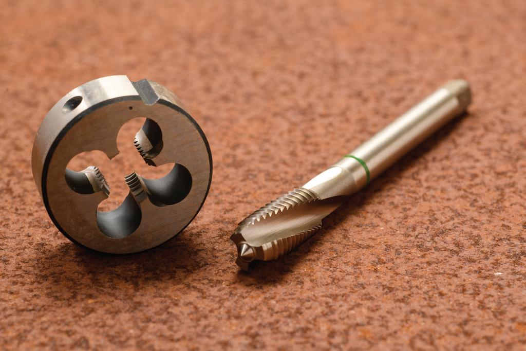
• Tapertap • Second cut tap • Plugtap • Tap wrench

Safe use of threading tools and equipment Equipment Use Safety Tap and tap wrench
Used for cutting threads on the inside of a drilled hole Initial hole must be drilled to the correct tapping drill hole size for the thread type and size Use thread cutting fl uid to lubricate the process Sets of taps must be used in the right order: taper, second cut and then plug Use correct technique and lubrication to prevent hardened steel taps from snapping or shattering in use. Wear eye protection. Avoid skin contact with swarf and thread cutting fl uid.
Die and die stocks Used for cutting threads on the outside of a metal rod Rod must have correct diameter for the thread type and size Thread cutting fl uid used to lubricate the process usually supplied as a set for a given thread type and size Tap and die used in thread cutting. DRAFT
Practise it! Remember it!

State the correct order in which a set of three taps is used to thread hole. (1 mark) • Taps cut internal threads (for example, nut). • Dies cut external threads (for example, bolt). • Use holes and rod sizes appropriate to the threads being cut. • Poor technique and too much force can cause taps to snap or shatter.

Wasting processes: Laser cutting see p.70
What you need to know
• The tools, equipment, steps and safety measures used when laser cutting.
Laser cutting uses a computer-controlled laser to cut complex shapes in a range of sheet materials.
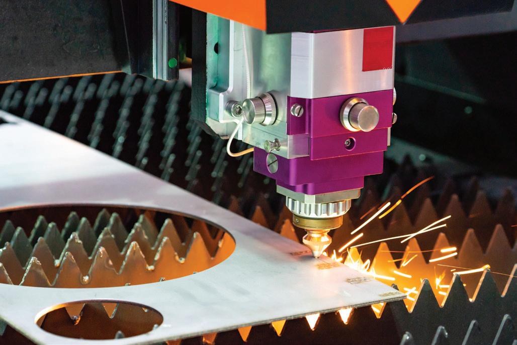
Types of laser cutting tools and equipment Computer with computer aided design (CAD) software; laser cutting machine; fume extraction and fi ltration equipment The image shows a laser cutter being used to cut complex shapes in sheet metal. Safe use of laser cutting equipment Equipment Use Safety CAD Generates CAD drawing of 2D components Exports CAD data in a format readable by the laser cutter Laser radiation can cause sight loss and severe burns. Use only when trained in the safe Laser cutting machine Uses CAD data to control movement of the laser operation of the equipment. head and cut complex shapes from sheet materials Use appropriate laser power and Laser makes cuts by causing localised extremely speed according to the material high temperatures that vaporise material type and thickness being cut. Laser power limits materials that can be cut (high Ensure all guards are in place power lasers are required to cut metals >300W) prior to use. Fume extraction and Ensure that fume extraction and fi ltration fi ltration is used.Operation controlled automatically when the laser is in use Extracts fumes generated when cutting Filters out harmful particulates DRAFT
Practise it! Remember it!


State two advantages of using a laser cutter instead of a coping saw to cut out a batch of ten identical components in acrylic sheet. (2 marks) • Laser cutting is used to cut 2D components from fl at sheets. • Component production is accurate and repeatable. • Component design changes are quick and easy. • Laser cutters cost from £10k to £250k.

Wasting processes: Milling/routing see p.70
What you need to know
• The tools, equipment, steps and safety measures used when milling/routing.
Milling and routing are similar wasting processes that use a rotating cutter to remove material from a workpiece. Milling is used primarily to machine metals and routing to cut and shape wood and manmade boards.
Types of milling/routing tools and equipment Equipment: Vertical milling machine, portable router Tools: End mill (face milling and slot cutting), slot drill (plunge and slot cutting), face mill (face milling), routing bits (wide range available for slot cutting and edge profi ling) Work holding: Machine vice, clamps Safe use of milling machines and routers Equipment Use Safety Milling machine Workshop machine for accurately cutting fl at surfaces and slots in metal components using a rotating tool Rotating tool is in a fi xed position Clamped workpiece is fed into the tool by moving the machine table in X, Y and Z directions Speed, feed and depth of cut are set according to the workpiece material, tooling and feature being machined Use only when trained in the safe operation of the equipment. Use appropriate operational parameters according to the material, tooling and feature being machined. Clamp the workpiece securely. Ensure all guards are in place prior to use. Router Portable handheld machine for cutting slots and edge profi les in wood and manmade board Wear eye protection and substantial footwear. High speed tool rotation Secure long hair and loose clothing, Limited guarding and remove rings and jewellery.
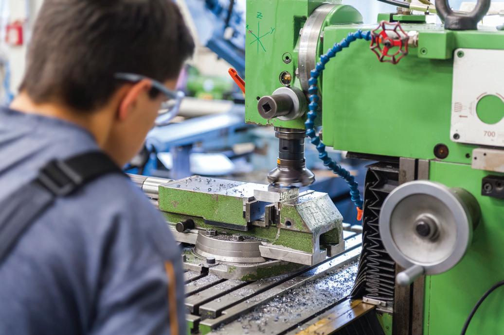
Machining a fl at surface on a workpiece using a vertical milling machine with face mill tooling. DRAFT
Practise it! Remember it!


Which of the following would be most appropriate when machining the fl at mating surface on an aluminium engine head? A vertical milling machine with face mill tooling B handheld router with profi ling tool C vertical milling machine with end mill D vertical milling machine with slot drill (1 mark) • Milling is most common in engineering applications when machining metals accurately (slot cutting and face milling). • Routing is most common in woodworking applications (slot cutting and edge profi ling).

Wasting processes: Turning see p.70
What you need to know
• The tools, equipment, steps and safety measures used when turning.
Turning is wasting process that is used to machine round bar. This might include reducing the diameter of the bar, making the ends of the bar fl at and square or drilling/boring a hole along its central axis.
Types of turning tools and equipment Equipment: Centre lathe Tools: Facing tool (makes ends fl at and square), parallel turning tool (reduces diameter), parting tool (separates fi nished component from bar stock), boring tool (for holes larger than 13 mm diameter, twist drill (for holes up to 13 mm diameter) Work holding: 3-jaw lathe chuck
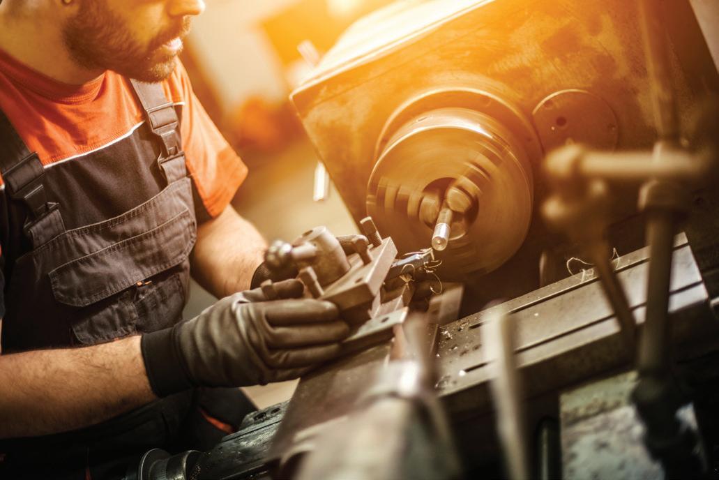
A centre lathe being used to turning a cylindrical component.
Turning operations: centre lathe Use Safety • Workshop machine for accurately shaping a rotating metal bar using a fi xed single point tool. • Turning tools are fed into the rotating workpiece by moving the tool post in the X and Y directions. • A fi xed twist drill mounted in the tailstock can be used to drill a central hole in the face of the workpiece. • Speed, feed and depth of cut are set according to the workpiece material, tooling and feature being machined.

• Use only when trained in the safe operation of the equipment. • Use appropriate operational parameters according to the material, tooling and feature being machined. • Clamp the workpiece securely. • Ensure all guards are in place prior to use. • Wear eye protection and substantial footwear. • Secure long hair and loose clothing, and remove rings and jewellery. Remember it!Revise it! DRAFT Make a poster outlining the safety precautions necessary when carrying out turning operations on a centre lathe. Include appropriate illustrations of safe practice sourced online. • Turning is carried out on a centre lathe. • It is most commonly used to machine a round bar into the required shape by parallel turning, facing, drilling and boring. • Turning in engineering applications is most often used to machine metals (although a wide range of other materials can be turned).


Shaping processes: Sand casting see p.71
What you need to know
• The tools, equipment, steps and safety measures used in sand casting.
Sand casting is a shaping process where molten metal is poured into a green (resin bonded) expendable sand mould.
Sand casting process
1
3
strickling off sand drag flat sided half pattern
Half pattern of cast component is placed in the bottom of the cope and covered with compacted green sand. Drag is inverted and cope bolted in place. Second half of pattern and pins for sprue and riser are added.
cope
sprue pin flat sided split pattern Cope is fi lled with compacted green sand. A pouring basin is formed around the sprue pin. pouring basin sand sand 4 sprue hole 2 DRAFT Drag and cope are split. Pattern and pins are removed to leave the mould cavity, sprue and runner. Sand is removed to form channels or gates connecting the mould cavity, sprue and riser.
sand
vents
mould Drag and cope are securely bolted together. Pins are used to add vents that allow gases to escape from the mould cavity during casting.
Molten metal is poured into the pouring basin and into the sprue. Pouring is stopped when molten metal emerges from the riser.
6
molten metal
vents 7 Once it has cooled the mould is broken off the component. Much of the green sand can be reused to make new moulds. 8 During fettling the sprues, gates, risers and any fl ash formed along the mould parting lines are cut or ground off. Waste metal is recycled for use in new castings. Safety Sand casting is a manual process and so comprehensive PPE is required when carrying it out. This might include foundry boots, gaiters, gloves, eye protection, a leather apron and fi re retardant clothing.DRAFT
riser
Revise it!

Create fl ashcards to help match up the unfamiliar technical terms that are used in sand casting with their defi nitions (see Remember it!)
Remember it!

The sand casting process uses a range of specifi c technical terms that need to be remembered. Make fl ashcards to match the terms with the defi nitions.
Drag Cope Sprue Riser Gate Pouring basin Patten
Shaping processes: Die casting see p.72
What you need to know
• The tools, equipment, steps and safety measures used in die casting.
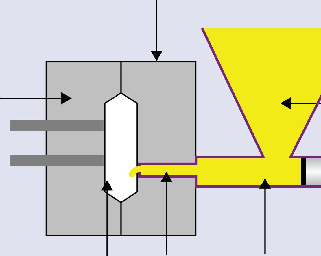
Hot chamber die casting is a shaping process in which high pressure molten metal is forced into two-piece reusable hardened steel dies to make complex three-dimensional components.
Hot chamber die casting


Cover die Molten metal Piston Pressure chamberSprueCavity Ejectordie Ejectorpins Safety Molten metal at high pressure can cause severe burns and so the whole process is enclosed during each casting cycle. 4 The molten metal cools and the casting solidifi es. 3 The plunger forces a pre-measured shot of molten metal into the die cavity. 5 The two-piece die is separated. 6 Ejector pins push the casting out of the die. 7 Any remaining sprue or fl ash formed along the parting line is ground off the casting. 8 The two-piece metal die is closed and the cycle repeats. 2 Molten casting metal fi lls the pressure chamber. 1 The two-piece metal die containing the mould cavity is held closed. DRAFT The die casting process uses a range of specifi c technical terms that need to be remembered. Make fl ashcards to match the terms with defi nitions.


Revise it!

Draw a large sketch of the hot chamber die casting process. Add appropriate labels to identify each part using appropriate technical terms.
Remember it!

Mould cavity Pressure chamber Plunger Ejector pin Sprue Parting line Flash
What you need to know
• The differences between sand and die casting, including the types of mould used.
There are several signifi cant differences between sand casting and die casting that will affect the selection of these shaping processes for particular applications.
Characteristic Sand casting Die casting Mould use Expendable: single use sand moulds are broken away from each component Reusable: hardened steel dies can produce up to 100 000 castings Component size Medium to large: detail can be lost on small sand castings and so it is better suited to larger components Small to medium: equipment and tooling cost limits the size of die cast components Casting metal Iron, steel, brass, aluminium Brass, aluminium Casting metal melting point Any: even high melting point metals can be cast because high temperatures do not affect the sand mould Low: high melting point metals cause damage to the steel tool Tooling costs Low: a wooden pattern and green sand is usually all the tooling that is needed High: hardened steel die cast tooling is relatively expensive depending on its size and complexity Tooling lead time Low: patterns are relatively quick and easy to make Medium to high: machining and polishing hardened steel dies is diffi cult and time consuming Equipment costs Low: a manual process where castings are hand poured, requiring minimal equipment High: a highly automated process using specialist equipment Dimensional accuracy Low: require secondary machining processes to achieve high dimensional accuracy, for example, on mating surfaces High Surface fi nish Poor: component fi nish is only as good as the surface of the sand mould cavity Very good: excellent surface fi nish can be achieved by polishing the mould cavity Batch size Low to medium: high labour costs and long cycle times costs limit economic batch size
High: low labour cost and short cycle times are ideal for large batch sizes DRAFT
Practise it!

Which of these two processes, sand casting and die casting, would be best suited to manufacturing a batch of 20 000 cast iron engine blocks? (1 mark)
Remember it!

When choosing processes for use in a particular application it’s essential that you understand their characteristics.
Shaping processes: Injection moulding see p.73
What you need to know
• The tools, equipment, steps and safety measures used in injection moulding.
Injection moulding is a shaping process in which high pressure molten thermoplastic is forced into two-piece reusable hardened steel moulds to make complex three-dimensional components.


Hopper
Heater Mould Motor/Ram Screw Characteristic Injection moulding Mould use Reusable: hardened steel dies can produce up to 200 000 mouldings Component size Small to medium: equipment and tooling cost limits the size of injection moulded components Material Thermoplastics: for example, ABS, polycarbonate Tooling costs High: hardened steel moulding tools are expensive depending on size and complexity Tooling lead time Medium to high: machining and polishing hardened steel dies is diffi cult and time consuming Equipment costs High: injection moulding is a highly automated process using specialist equipment Dimensional accuracy


High Surface fi nish Very good Batch size High: low labour cost and short cycle times are ideal for large batch sizes Safety 4 The thermoplastic cools and the moulding solidifi es. 3 A hydraulic ram pushes the whole screw forward to force a pre-measured shot of molten thermoplastic into the mould cavity. 5 The mould opens and ejector pins push the fi nished component out. 6 Sprues and fl ash are removed from the components. 2 Granules melt as they are carried past heating elements by a rotating screw. 1 Thermoplastic granules are fed from a hopper into the heating chamber.DRAFT Molten plastic at high pressures can cause severe burns and so the whole process is enclosed during each moulding cycle.

Revise it!

Draw a series of labelled sketches to illustrate the steps involved in injection moulding.
Remember it!

Only thermoplastic materials that soften and fl ow when they are heated can be injection moulded.
Shaping processes: Powder metallurgy see p.74
What you need to know
• The tools, equipment, steps and safety measures used in powder metallurgy.
Powder metallurgy is a metal forming manufacturing process that can be used as an alternative to machining, forging or casting for metallic components.
Powder metallurgy
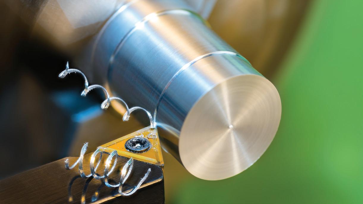

Conventional powder metallurgy is a metal forming process that heats a compacted mix of fi ne metallic powders to just below their melting points. This fuses or sinters the particles of powder together into solid metallic components. Powder metallurgy processes: • generate very little waste • give good surface fi nish • have good dimensional accuracy • can make porous or full density parts. It is also possible to add non-metallic ingredients to powder metallurgy mixes. For example, tungsten carbide (an engineering ceramic) is mixed with cobalt powder and moulded into tools for use in machining. Conventional powder metallurgy process Manufacture and grading of fi ne metal powders Compacting powder mix in a mould to make ‘green’ components Finished component
Mixing/blending metal powders, binders and lubricants


Fusing powder particles together in sintering oven Carbide lathe inserts are made by powder metallurgy. DRAFT
Practise it!


Explain what is meant by the term ‘sintering’. (2 marks)
Remember it!

Powder metallurgy makes solid components by sintering together fi ne metal powders.
Forming processes: Forging see p.75
What you need to know
• The tools, equipment, steps and safety measures used in forging.
Hot forging is a forming process that uses force to reshape heated metal into a desired shape. Forged components are both stronger and tougher than equivalent cast components.
Hand forging Hot press forging
Blacksmiths heat steel until it becomes malleable and can be reshaped with a hammer. This type of forging has been used for centuries. Press forging creates the required component shape in a single operation by taking a heated blank or billet of metal and squeezing it between shaped dies. Excess material is squeezed out between the dies and forms a fl ash that must then be trimmed or ground off. Ram
Punch Workpiece Flash Die Anvil Tools and equipment Hand forging • Forge (coal/charcoal fi re with bellows to add air reaching temperatures over 1000 oC) • Anvil • Hand tools, for example, tongs, forging hammer, tongs, chisels, punches and drifts Industrial press forging • Flywheel or hydraulic press (able to exert hundreds or thousands of tonnes depending on the size of the component being forged) • Forging dies (two piece hardened steel dies with a cavity in the shape of the component being forged)
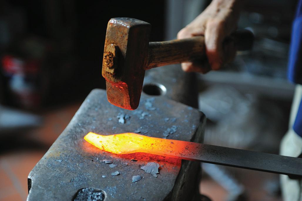
Safety Like all hot working processes, forging is potentially dangerous and appropriate PPE must always be worn, namely: • fi reproof clothing • gauntlets • apron • safety glasses • foundry boots • hearing protection. DRAFT Industrial forging presses exert extremely high forces and so guards are essential to prevent trapping or impact injuries. Hot forging depends on heat to make metals malleable so they can be re-shaped.

Revise it!

Draw a spider diagram to summarise forging. Include headings such as: safety, tooling and equipment.
Remember it!

Forming processes: Press forming see p.76
What you need to know
• The tools, equipment, steps and safety measures used in press forming metal.
Press forming is a cold forming process that bends or shapes sheet metals into components like car body panels, white goods body panels (for example, washing machines, fridges, tumble driers) or desktop computer cases.
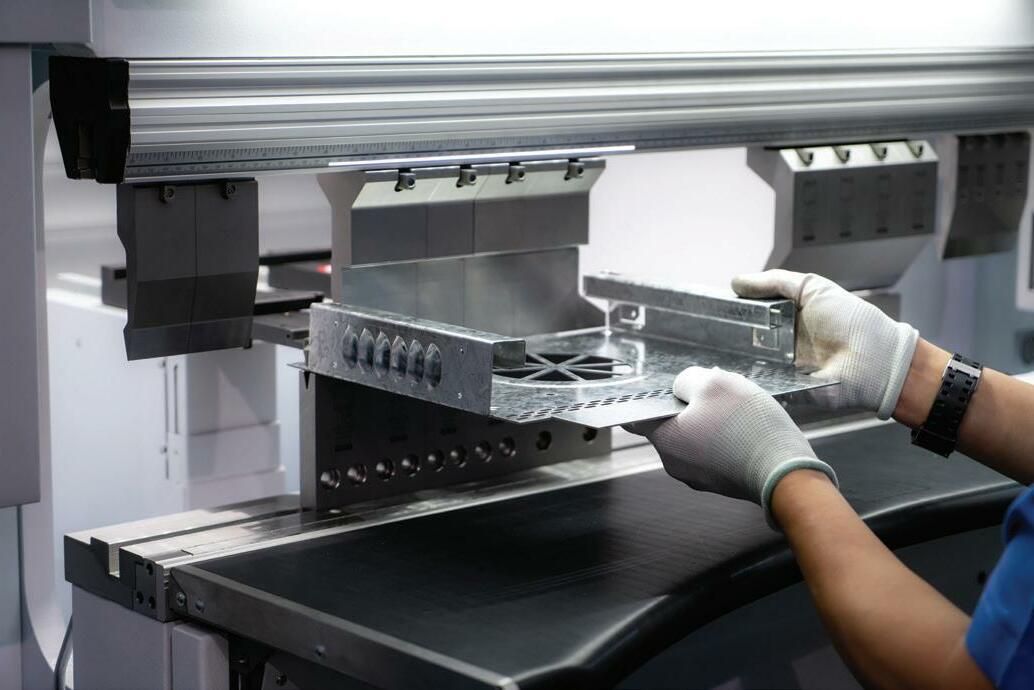
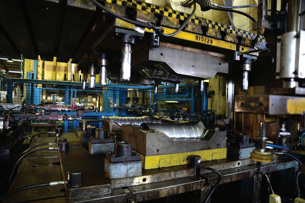
Press forming: dedicated tooling Complex 3D shapes such as car body panels can be formed in one operation using dedicated two-piece press tools. These are trimmed after forming. Complex, curved car body panels are made using dedicated press tools. Press forming: general purpose tooling Sheet metal blanks can be formed into simple folded panels or boxes using a general-purpose block and blade tool on a forming press. A pre-cut fl at metal blank being folded into a box using a CNC press with block and blade tooling.
Tools and equipment Large, dedicated press tools are expensive to make, can only be justifi ed if thousands of the and can only be used on large, powerful hydraulic presses. General purpose block and blade tooling is much more affordable and requires a less powerful, smaller press but limits component complexity. A CNC controlled press brake with adjustable stops can form a series of folds easily and accurately.

Safety Sheet metal has sharp edges and sharp corners and must be handled carefully. A range of PPE should be used including: • gloves • safety boots • eye protection • hearing protection. DRAFT Presses can cause impact or crushing injuries and so machine guards must be used. These are often electronic ‘light guards’ that prevent the press from moving until the operator is at a safe distance. Press forming is a cold working process to shape sheet metal components.

Practise it!

Explain why dedicated press tools are only used when thousands of the same component need to be made. (3 marks)
Remember it!

What you need to know
• The tools, equipment, steps and safety measures used in strip heating polymers.
Strip heating is a forming process for making simple components by making bends in thermoplastic sheets.
Using a strip heater


Safety • Do not touch the heating element. • Do not touch the area of material that is being heated. The component is folded to the angle required and held in position as the material cools. The strip of material along the fold line heats up and becomes pliable. Once fully cooled the material becomes rigid and the component holds its new shape. The component is placed on the strip heater so that a fold line is directly above the heating element. A fl at blank (or net) of the formed component is cut out, often using a laser cutter. DRAFT • Do not leave materials on the strip heater unsupervised. • Allow material to cool fully before handling. • Line bending with a strip heater only works with thermoplastic sheet materials. • Products are limited to those designed with simple straight bends.


Revise it!

Create a poster that outlines the process of strip heating. Remember to include safety information.
Remember it!

Forming processes: Vacuum forming see p.78
What you need to know
• The tools, equipment, steps and safety measures used in vacuum forming.
Vacuum forming is used to make complex, curved, thin-walled hollow shapes from thin thermoplastic polymer sheets.
Vacuum forming Heater
Clamp Mould
Plastic sheet Platen A thin thermoplastic The platen is raised A vacuum pump reduces the pressure under the polymer sheet is and pushes the mould. This forces the pliable thermoplastic sheet clamped in place and mould into the pliable into the mould. As it cools, the sheet hardens into heated until it softens thermoplastic sheet the new shape. This can then be removed from the and become pliable. from below. vacuum former and trimmed. Mould characteristics Vacuum forming moulds are made from a range of materials including MDF, wood and aluminium depending on their complexity and the number of times that they need to be used. The shape of a mould needs to include a draft angle and avoid undercuts to ensure that formed components can be removed easily. Vacuum formed shapes must be relatively simple: • with no sharp corners that could cause tearing • with no fi ne details that might not form properly (such as small lettering)


• with well-spaced features to prevent webbing • with limited depth to prevent excessive thinning of the material. Safety • Do not touch the heating element. • Do not touch heated material. • Do not leave materials to heat up unsupervised. DRAFT • Allow formed material to cool fully before handling fi nished components.

Practise it!

Outline two limitations that need to be considered when designing vacuum formed products. (2 marks)
Remember it!

Vacuum forming: • only works with thin sheets of thermoplastic materials • is suitable for thin-walled components.
What you need to know
• The tools, equipment, steps and safety measures used in moulding composites.
Glass fi bre reinforced polymer composites (GFRPs) consist of strands of glass fi bre held together in a polyester resin matrix.


Lay-up Suitable for lightweight GFRP products with high strength to weight, such as canoes. 1 Release agent is applied to the surface of a single piece wood or fi breglass mould. 2 A resin gel coat is applied, which will form the outer skin of the fi nished product. 3 Long strands of glass fi bre often woven into matting are applied in layers and coated with polyester resin using a paint brush. A roller is used to compact each layer and expel any air bubbles. 4 Suffi cient layers are applied to give the required strength and rigidity. 5 Once the resin has cured, the fi nished component is removed from the mould and trimmed. Spray-up Spray up is quicker and easier than lay-up but results in greater wall thicknesses and more weight to achieve the same strength and rigidity. Suitable for general purpose GFRP products, such as covers and panels. 1 Similar mould preparation and application of gel coat as in lay-up. 2 A mix of chopped fi bres and polyester resin are applied to the mould with a spray gun to the required thickness. 3 A roller is used to compact the fi bre/resin layer and Suitable for general purpose GFRP products, such as covers and panels. Lightweight GFRP kayak manufactured using the lay-up technique. DRAFT expel any air bubbles. 4 Once the resin has cured, the fi nished component is Close up showing random orientation of removed from the mould and trimmed. chopped strands typical of the spray-up technique.


Practise it!

Describe the difference between fi bre alignment in GFRP composites made by lay-up and spray-up. (2 marks)
Remember it!

• GFRP stands for glass fi bre reinforced polymer. • GFRP composite is made up of glass fi bres held in a polyester resin matrix.
What you need to know
• The tools, equipment, steps and safety measures used in moulding composites.
Carbon fi bre reinforced polymer composites (CFRPs) consist of strands of glass or carbon fi bre held together in a polyester or epoxy resin matrix. The image shows lightweight bicycle frames, wheels, seat posts and other components are all made from CFRP.
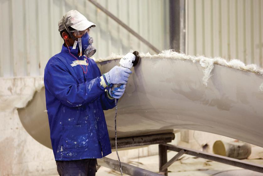
Vacuum bagging Suitable for small, lightweight, thin walled CFRP products, such as racing bicycles, with exceptional strength to weight characteristics. 1 A wax release agent is applied to the surface of a single piece mould. 2 Woven carbon fi bre sheets pre-impregnated with epoxy resin are laid into the mould. 3 This is then placed in a plastic bag and all the air is evacuated using a vacuum pump. 4 Inside the bag, the sheets are compressed together and forced into the mould. 5 This is then placed inside an autoclave where increased pressure and temperature is applied, causing the resin to cure. 6 Once the resin has cured, the fi nished component is left to cool, removed from the mould and trimmed. Safety Dust from trimming and fi nishing fi bre materials and cured resins is harmful if inhaled. The chemicals mixed to make resins are both toxic to humans and harmful to the environment. So, depending on the processes being carried out, PPE might include: • eye protection • respirator • nitrile gloves


• disposable coverall with a hood • disposable over shoes. DRAFT • CFRP stands for carbon fi bre reinforced polymer. • CFRP composite is made up of carbon fi bres held in an epoxy resin matrix.

Revise it!

Create a short PowerPoint presentation to describe three methods used to manufacture fi bre composite materials. Use appropriate illustrations sourced online.
Remember it!

Additive manufacturing: 3D printing see p.80
What you need to know
• The tools, equipment, steps and safety measures used in 3D printing.
3D printing uses a computer model to manufacture a complex three-dimensional component from thermoplastic polymer.

Fused deposition modelling (FDM) In FDM, specialist software is used to split a 3D computer model of the required component into thousands of thin slices. Each slice is then printed by a moving nozzle that deposits thin layers of thermoplastic polymer, one on top of another, until the component is complete. The printer should have an enclosure to ensure that users cannot touch the heated nozzle, print bed or polymer. Extruder Hot end Thermoplastic components manufactured using FDM.


Filament spool

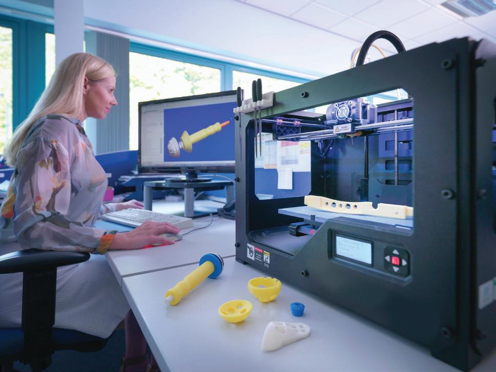
After each layer, the nozzle moves up to allow the next layer of polymer to be deposited. Each slice of the model is recreated as a 2D layer of extruded polymer deposited from the nozzle. The extruder melts the fi lament and forces it out of the nozzle at 190–285°C. PLA or ABS thermoplastic is supplied to the heated extruder unit from a spool of thin fi lament. DRAFT

Print bed
Simplifi ed diagram of an FDM 3D printer.
Practise it!

Outline one important limitation of manufacturing components using FDM. (1 mark)
Remember it!

• FDM stands for fused deposition modelling. • FDM extrudes layers of thermoplastic to build up components slice by slice.
Joining processes: Brazing see p.81
What you need to know
• The tools, equipment, steps and safety measures used in brazing.
Brazing is a common method of permanently bonding steel (and other metal) components together.
Brazing
Brazing uses a brass alloy to bond or stick two components together. This differs from welding, which joins components by melting and fusing the parent metal together. Thin-walled components like steel bicycle frames are brazed rather than welded as the lower temperatures involved prevent distortion. The image shows brazing steel with an oxyacetylene torch and a fl ux coat brass brazing rod. Equipment • Oxy-acetylene equipment (including torch, gas bottles, pressure regulators, etc.) • Brazing hearth or welding bench • Emery cloth (to help clean the surfaces being brazed) • Brazing rod (often supplied complete with a layer of fl ux) • Flux (applied to prevent oxidation which can prevent braze from wetting the surfaces being bonded)
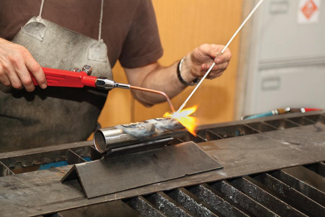
Safety • Care must be taken when carrying out any hot working process. • Good ventilation is required to remove toxic fumes. • Brazed components must be left to fully cool before handling. • Brazing should be carried out away from fl ammable materials (including clothing). PPE must include: • gas welding/brazing goggles (Shade number 5) • fi reproof apron. DRAFT • Brazing uses a brass alloy to bond metal components together. • Brazing bonds components together using surface adhesion. It does not fuse the parent metal like in welding.

Practise it!

Explain one reason why brazing is used instead of welding on the thin-walled steel tubing used to manufacture bicycle frames. (2 marks)
Remember it!

Joining processes: MIG/MAG welding see p.xx
What you need to know
• The tools, equipment, steps and safety measures used in MIG/MAG welding.
Welding is a method of permanently joining similar metal components. MIG/MAG welding is a common form of gas-shielded electric arc welding.
MIG/MAG welding Safety
MIG/MAG welding both use: • an electric arc to provide the necessary heat to melt the component parent metal • a spool of fi ller wire matching the component parent metal that is automatically fed into the weld pool (instead of using a welding rod) • a shielding gas to prevent oxidation of the weld pool (instead of using a chemical fl ux). MIG (metal inert gas) uses pure argon for shielding and is used for welding non-ferrous metals. MAG (metal active gas) uses a mix of argon, and carbon dioxide for shielding and is used for welding steel.
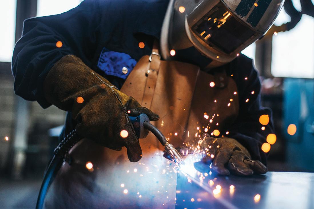
• Care must be taken when carrying out any hot working process. • Good ventilation is required to remove toxic fumes. • Welded components must be left to fully cool before handling. • Welding should be carried out away from fl ammable materials (including clothing). • Electric arc welding emits harmful UV light that can cause eye damage. PPE must include: • arc welding full face mask or helmet (shade number 10–14) • fi re retardant coverall • fi reproof welding apron • welding gloves • safety boots. Equipment • MIG/MAG welder (including earthing lead, welding torch, wire feed mechanism and shielding gas controls) • Welding wire (matching component parent metal) • Shield gas (gas bottle, pressure regulator Extensive PPE is necessary when carrying out DRAFT MIG welding. and pipework) • Anti-spatter spray (applied to surfaces around the weld to prevent weld spatter sticking)

Practise it!
What is the difference between MIG and MAG welding? (1 mark)
Remember it!


• Welding processes fuse together components made from similar materials. • MIG/MAG welding uses an electric arc to generate heat that emits harmful UV light.
Joining processes: Riveting see p.83
What you need to know
• The tools, equipment, steps and safety measures used in riveting.
Riveting is a method of permanently joining two or more overlapping metal sheets or plates. Riveting can be used to join dissimilar metals.
Hammered rivets
Hammered steel rivets are used on metal bridge structures, electricity pylons, boilers and water tanks although they have been replaced in many traditional applications by welded joints. Hot riveting process • Rivets are heated until they become red hot and malleable. • A hot rivet is inserted into a hole through both components and held fi rmly in place. • The other end is hammered (or peined) over, often using a pneumatic hammer. • As the rivet cools it contracts and further tightens the riveted joint.
Rivets are inserted in a hole through two plates. Pop rivets Once hammered over (or peined) the rivet permanently joins two plates. Pop rivets can be inserted blind (with no access to the back side of the joint). They are used extensively in sheet metal work, for example, assembling enclosures, fi xing hinges, attaching name plates. Pop riveting process • Insert rivet into a hole through both components. • Use a rivet gun to pull the steel pin (mandrel) which collapses and expands the tubular rivet on the blind side of the joint. • The steel pin breaks off when a pre-determined force is reached, leaving the rivet in place.
Enlarged pop rivet Steel pin Hollow rivet body
Completed rivet Pin breaks off Rivet gunDRAFT
Practise it!

What is meant by the term ‘blind riveting’? (1 mark)

Remember it!
Riveting is a permanent (or semi-permanent) method of fi xing together sheet materials or metal plates.
Joining processes: Mechanical fastening see p.83
What you need to know
• The tools, equipment, steps and safety measures used in mechanical fastening.
Mechanical fasteners allow components, including those made from different materials, to be joined together. They can be undone and removed to allow products to be disassembled.

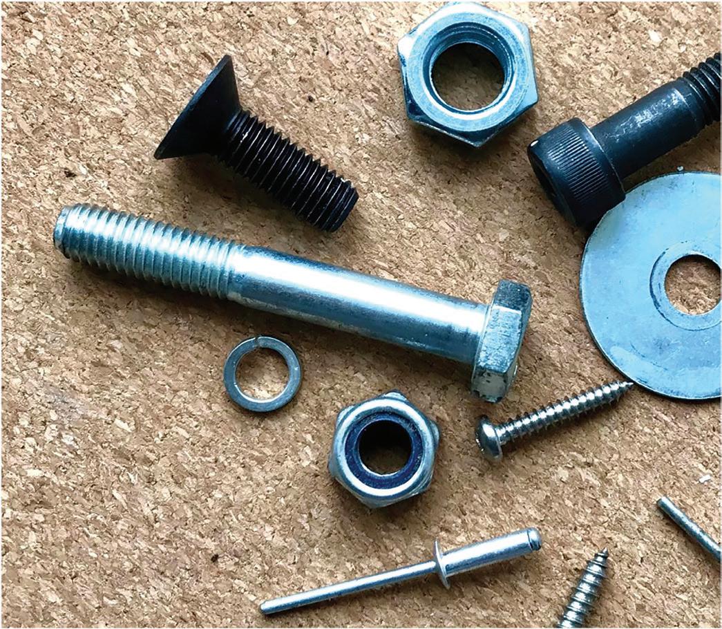

Mechanical fasteners Penny washer: fl at washers are used with nuts and bolts to protect the surface of components and spread joining forces. Hexagon nut: nuts have an internal thread that screws onto compatible threaded components or bolts. Tools: spanner or socket wrench Hexagon bolt: bolts have an external thread that screws into compatible threaded holes. They are often used in clearance holes with nuts and washers to join two components. Tools: spanner or socket wrench Pozi-drive self-tapping screw: self-tapping screws have a special hardened external thread that can cut a matching internal thread in thin sheet materials or thermoplastic components. Tools: screwdriver DRAFT
Practise it!


Explain why non-permanent fasteners are used so commonly in mechanical assemblies and mechanisms. (2 marks)
Remember it!

Non-permanent mechanical fasteners include: • nuts • bolts • washers • self-tapping screws.


