
9 minute read
FLUKE NETWORKS IS THIS FIBER LINK GOOD?


IS THIS FIBRE LINK GOOD?
THAT’S A COMMON QUESTION, BUT THE RESPONSE MIGHT BE “GOOD FOR WHAT?” WERNER HEEREN, REGIONAL SALES DIRECTOR AT FLUKE NETWORKS, LOOKS AT HOW THE PERFORMANCE OF FIBRE LINKS CAN BE DETERMINED.
Advertisement
THE ATTENUATION OR “LOSS” OF A FIBER
link is the primary determinant of its ability to carry traffic. That sounds simple, but things quickly get more complicated than that. Let’s look at how the performance of fiber links is determined and how you determine if it’s “good”.
When you put a signal into one end of a fiber, the signal that comes out the other end is smaller. The difference between the input and the output signals is called insertion loss. If there is too much loss, the signal coming out the end of the fiber will be too small for the receiver to interpret.
Loss is expressed in decibels or dB, where every halving of the signal strength is represented by 3 dB. If the output signal is half of the input, that’s 3 dB of loss, ¼ is 6 dB of loss, etc.
HOW MUCH LOSS IS TOO MUCH?
The TIA and ISO define a loss limit or budget based on the length of the fiber and the number of connectors and splices. There are multiple versions of these parameters for different types of connectors and fiber, so for this example, we’ll use OM5 multimode fiber, which has the same limits in the TIA and ISO (Table 1). To calculate the loss budget of a link, just perform a calculation as shown:
You might realise that adding more connectors and making the fibre longer will give you a higher limit and possibly make it easier to pass. What if you patched together five of the links described above? That combined link would have a TIA limit of 21.75 dB. So if it measured 20 dB of loss, it would pass the limit, but would it be good? Well, that brings us back to the question of “good for what?”
WILL MY APPLICATION RUN ON THIS LINK?
If you are responsible for a network, the “good for what” question typically means “good for the application I want to run”, for example 10 or 40 Gig Ethernet. For example, looking at a spec for a common 40GBASE-SR4 transceiver shows that the minimum transmit power is -7.6 dBm and the minimum receive power is -9.9 dBm. This means that the loss on the link would need to be less than -7.6 dBm – - 9.9 dBm = 2.3 dB. Neither of our “good” links above would work.
Rather than look at the individual product specs, it makes more sense to use the IEEE limits for applications. These are the limits that the designers of networking gear use to design their products. The IEEE specifies the amount of loss and the length of the fiber for each application. You can find the limits for most common applications online or in the Fluke Networks Versiv Limit Lines document (registration required) – just search for your application, for example, “40GBASE-SR4”, and you’ll find a table like the one at right.
Depending on which type of cable you’re running, just measure the loss and length of the fibre and compare it to the appropriate limits for the type of cable you’re running. For example, if your OM4 measures 1.1 dB of loss at 850 nm wavelength and 125 meters, your cable will support 40GBASE-SR4.
The basics of loss measurement are straightforward and can be performed with relatively inexpensive tools. A reference measurement is made between the light source and power meter and recorded. Then links can be measured, and the reference measurement is subtracted from the observed measurement to determine the loss of the link being tested. Setting a reference for accurate measurements requires following a few steps correctly, which we won’t go into here. If you’re interested, just search for “1-jumper reference setting” on the internet to learn the basics.
AND NOW, REFLECTANCE
Over the last few years, a variety of short-reach single mode applications have become popular. Unlike older single mode technologies, these technologies are engineered for shorter distances (1 km or less) using much less powerful and therefore less expensive transceivers. Unlike older singlemode technologies, they also have much more stringent loss requirements. Note that the long-range technologies can tolerate a large amount of loss, while the shorter range one have much tighter limits.
Single mode applications are much more sensitive to the reflectance of the connectors and splices in the link. (Reflectance is a measurement of the amount of light reflected from the connector back to the transmitter.) For this reason, the IEEE has specified reflectance requirements for these technologies. Connections should have reflectance of better than -45dB (in other words, a larger negative number). Connections with worse performance (reflectance of -35 dB to -45 dB) are allowed, however, if present, the loss of the link may need to be better than the 3.0 dB number above.
MADE TO MEASURE
Measuring the reflectance of connectors on a link is a little more difficult than measuring the loss, as it requires an Optical Time Domain Reflectometer (OTDR), which is typically more expensive than a light source and power meter (which is still needed to measure loss). One work around for this would be to use top quality connectors and go for the tightest limit shown below. For example, with four interconnects, make the conservative assumption that they’re all worse than -45 dB and make sure your link is better than 2.7 dB of loss. However, you should be aware that field polished connectors or those that get dirty or scratched can easily have reflectance worse than -35 dB, and your link will not operate properly – even if the loss is acceptable. Maybe you should have an OTDR handy after all!
GOOD JOB
So in order to answer the question, the link is “good” for your desired application if has acceptable amounts of insertion loss, the proper length, and good reflectance performance. Fiber length in km Number of mated connectors Number of splices 0.75 dB 0.3 dB3.0 dBx + +x x 0.25 km x 3.0 dB / km + 4 x 0.75 + 2 x 0.3 = 4.35 dB With a 250 m length, four connections and two splices, the budget would be: If the measured loss of your link is 4.35 dB or less, you’ve passed!
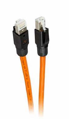
SIEMON Z-PLUG
SIEMON’S PATENT-PENDING Z-PLUG
offers quick, reliable high-performance plug terminations in the field for customlength direct connections to wireless access points, security cameras, LED lights, distributed antenna systems (DAS), building automation devices and any other IP-based and PoE-enabled devices deployed in today’s converged networks. The Z-PLUG exceeds all Category 6A performance requirements, and it can be terminated to shielded, unshielded, solid and stranded cables for maximum flexibility. The plug is compliant with UL 2043 for use in plenum air handling spaces, and can be terminated without the boot for connecting to devices with limited depth, such as cameras and access points.
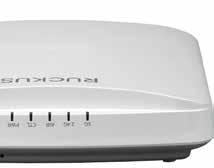
COMMSCOPE WIFI 6 ACCESS POINTS
COMMSCOPE HAS INTRODUCED
additions to its portfolio of access points supporting Wi-Fi 6 technology, bringing the benefits of higher data rates, increased capacity, improved power efficiency and better performance in environments with multiple connected devices.
In addition to the RUCKUS R750, introduced last year as the world’s first Wi-Fi CERTIFIED 6 access point (AP), CommScope added the R850, R650 and R550 indoor APs and T750 and T750SE outdoor APs. The APs will be Wi-Fi CERTIFIED 6 and are optimised for highly dense environments such as educational campuses, hotels and other venues such as airports and stadiums.
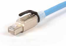
NEXANS HAS RELEASED A NEW Category 6A field installable plug as part of its LANmark-6A offer. This plug is designed to build Modular Plug Terminated Links (MPTL), an increasingly popular method to directly connect patch panels with network devices, such as Wireless Access Points and IP cameras. These devices are usually located near the ceiling, where there is often no possibility to install an outlet or other connection box.
MPTL are built with infrastructure cable terminated with an RJ45 jack on one end and an RJ45 plug on the other and are now standardised in TIA 568-2.D and specified in the draft version of ISO/ IEC TR 11801-9910 ED1.
In conjunction with LANmark-6A horizontal cable and the LANmark-6A Snap-In connector, configured in MPTL, the LANmark-6A Field Terminable Plug will support all Class EA applications, including 10GBase-T and Power over Ethernet up to 100W.
NEXANS A CAT 6A FIELD TERMINABLE PLUG
When designed and carried out following our Design Guidelines (for MPTL / 1-connector Channel) and tested according to our MPTL Field Test procedure, LANmark-6A MPTL installations qualify for a 25-year LANmark system warranty.
The LANmark-6A Field Terminable Plug is fully shielded, accepts cable of 6.0mm to 8.5mm diameter with AWG24 to AWG23 solid wires and is easy to install without the need for a special termination tool, apart from a pair of parallel jaw pliers.
Wireless networks today have expanded beyond Wi-Fi to include different IoT wireless technologies for multiple use cases from asset tracking to connected door locks. This has led to unmanageable, expensive, siloed wireless networks. These new APs spearhead an end-to-end converged architecture, eliminating overlay networks, and allowing cost savings and easy management using a variety of management options – SmartZone Network Controller, ZoneDirector, RUCKUS Cloud and RUCKUS Unleashed. These new APs also deliver comprehensive network intelligence powered by machine learning and artificial intelligence through RUCKUS Analytics.
Shaping the always-on communities of tomorrow—one smart city at a time

Tomorrow’s smart cities begin with intelligent network connectivity, available today from CommScope. With innovative wired and wireless infrastructure for in-building and outside plant, we power and connect today’s smart buildings and campuses.
CommScope brings it all together: flexible structured cabling with best-in-class fiber and copper technology, future-ready cellular and Wi-Fi mobility, high-reliability PoE and powered fiber, and the automated infrastructure management to help you monitor and control everything in real time.
Partnering with local and regional governments around the world, CommScope helps build smarter, safer and healthier places to live, work and play—one smart city at a time.
Your smart city begins with an even smarter network infrastructure. Start with CommScope.


