
ASSESSMENT 3: Envelope detail + prototype
135-139 WEST TERRACE, ADELAIDE SA 5000
ARCH 7033 ADVANCED CONSTRUCTION (M) 2023
ZHU DANNING, A1760370
BLUNSDEN ETHAN, A1803847
CURTIS SAMUEL, A1741893
LI JIAWEI, A1845209

A
PRIORITY STATEMENT:
) Designing a facade that embodies the movement and greenery of the roof, which can also allow breeze through the building.
- This was done to add interest to what was originally a very flat and boring facade, and to bring fresh air onto all floors without extensive HVAC systems.
B) Using green elements to insulate the buildings exposed roof and provide a habitat for birds.
- This creates the first step for a new green corridor from the city to the parklands, to liven up the city.
C) Maintaining a large open space within the ground floor’s arch structure.
- Achieved using a multi-directional truss system that bears onto the ground, alongside columns and cores at its ends.
- This results in a grand exhibition space on the ground level, and gives the appearance of a floating structure.









1 BUILDING ENVELOPE:
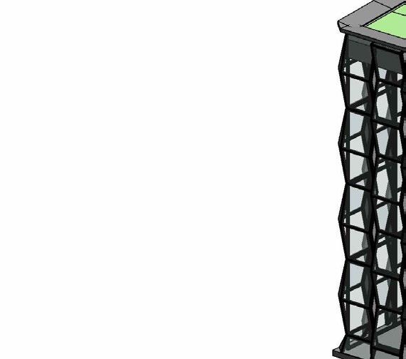
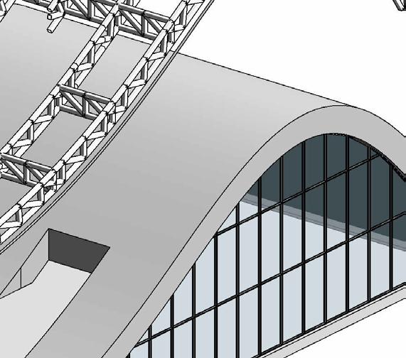
The building envelope takes advantage of curtain glazing panels in order to create the appearance of a ‘floating’ mass, and to show off the self-supporting truss arch exhibition space. The movements of the arch are reflected in the green roof above.

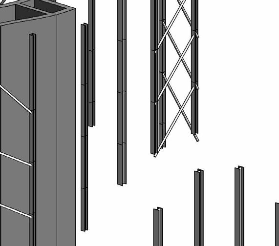
The facade is created using glass curtain walls and a system of angled, pivoting glazed panels and fixed aluminium panels, alongside vertically spanning green walls to create a rippling effect through the facade. This maximises views to the surroundings and allows airflow through.

STEEL BEAM AND GIRDER SYSTEM:
Supporting the floor plates and roof are a system of steel girders and secondary beams.
All steel girders are of the profile 700WC150, supporting any cantilevered columns or secondary beams. They span along the grid lines of the project, between the concrete cores and columns.
Secondary beams are 400x200x16 steel RHS, and are used to reduce the span of the floor plates to ensure that they do not span more than approx. 3.2m.

STEEL TRANSFER BEAMS:
Between the concrete cores where a column is impractical to place due to circulation, 800WB168 profile steel beams have been used to transfer the loads from the girder and beam system to the core, and into the ground.

4 ARCH TRUSS SYSTEM:
In order to achieve a grand, open exhibition space in the lower floor without intruding columns, a two-way Pratt truss system comprised of 250x250x16 SHS members. Each arched truss is braced horizontally by a secondary truss, which transfers the loads into 500WC440 columns and the concrete cores within the structure.

STRUCTURAL SYSTEM
The building will utilise a steel and concrete composite structure, using steel welded columns (WC), supporting a system of steel RHS beams and WB section girders.
The project initially was planned so that no beam would span further than approximately 9.5m, and all member sizes were determined based on this. However, since the building has been altered, spans no longer exceed approximately 8m. Member sizes, however, remain the same to ensure structural stability.
5 CONCRETE CORE AND BRACING
The building includes two 500mm thick concrete cores, each with a stair and lift shaft. Each core is 4040mm x 9100mm. Each lift can carry 13 people, and is rated to 1000kg.
These shafts are combined with an arrangement of 150x100 RHS steel diagonal bracing between columns arranged symmetrically throughout the building. This is done to provide bracing throughout the structure to combat lateral loads.
6 FLOOR PLATES
The floor plates within the building are 200mm thick, using a 75mm steel deck with concrete cast on top. This bears down on the steel girders and beams.
7 500 WC 440 COLUMNS
A combination of 350WC280 and 500WC440 steel columns have been used throughout the structure.
500WC440 columns are used in all areas where a column will bear directly onto the earth, to help bear the loads of any cantilevered sections and the trusses of the arch.
350WC280 columns are used in all areas where a column will NOT bear directly onto the earth, such as in cantilevers.
These columns support a smaller floor area than their 500 WC counterparts, and have been reduced in size to minimise their profile and weight.
 350 WC 280 COLUMNS
SIMULATED MEMBER UTILISATION
In order to test the effectiveness of the structure, Karamba3D was used. This specific simulation indicates the utilisation of each member throughout the structure, helping to demonstrate the distribution of loads throughout. This is done by calculating the ratio between the axial stress in the beam, and the yield strength of the beam material.
Red areas indicate where a member is under increased compression, while blue areas indicate where members are increased tension.
The simulation shows that the most problematic areas - where members are under the greatest stress - occurs within the large-spanning truss system within the lower arch structure. This is caused by not only the self-supporting nature of the arch, but also the added load of the structure above bearing down onto it.
These trusses bear the load of themselves and the building above to the ground in order to eliminate the reliance on columns within the lower floor, creating a more dynamic open exhibition space.
As no members reach a ratio of 100% utilisation, none are expected to fail, and the structure seems to be successful.


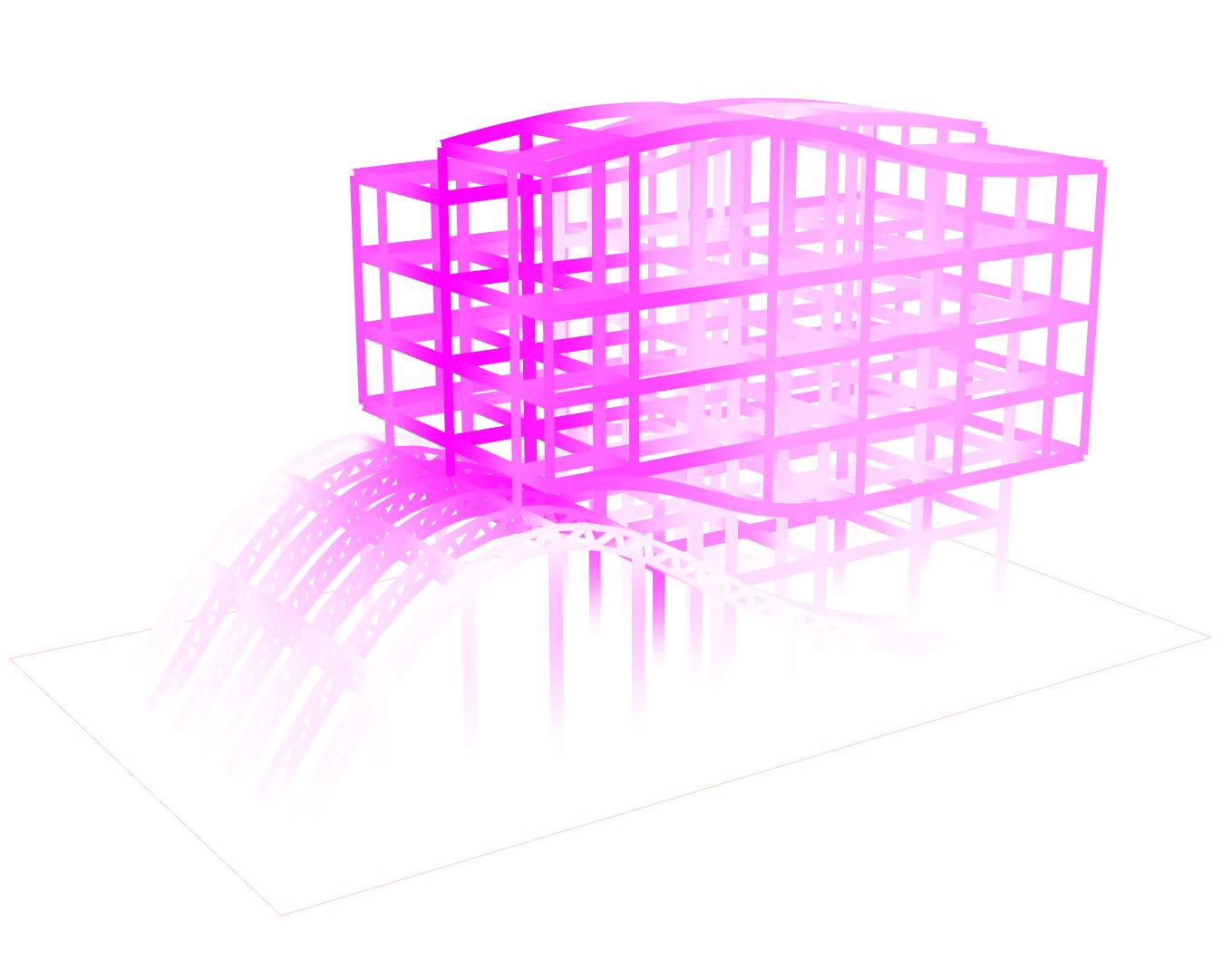
SIMULATED MEMBER DISPLACEMENT
This second simulation indicates the displacement of members throughout the structure, where white areas indicate least displacement, and purple areas indicate greatest displacement.
It can be seen that members experiencing the greatest displacement are those supported by the arch truss system. This follows a similar trend to the member utilisation simulation shown above, and seems to be a result of the truss transferring the above loads into the ground.
This indicates that perhaps a deeper or stronger member section is required to additionally support the truss structure, without relying on the addition of columns. This would be the ideal solution to maintain the grand, open nature of the exhibition space.
It should be noted that these simulations consider the dead loads of the building into consideration, loads imposed by gravity. However, they do not account for live loads or lateral loads that the structure may be subject to in reality.
MAX. DISPLACEMENT IN STRUCTURE: 0.54CM


FLASHING TO WRAP AROUND CAPPING AND SHELL
VEGETATION BEYOND: CREEPING BOOBILLA, MYOPORUM, AND OTHER LOW-MAINTENANCE VEGETATION
200mm GROWING MEDIUM COMPOSED OF 75% INORGANIC MATERIAL (CLAY, CRUSHED SLATE) AND 25% ORGANIC MATERIAL
FILTER FLEECE GEOTEXTILE FABRIC TO WRAP AROUND GROWING MEDIUM
DSE 40 WATER RETENTION AND DRAINAGE LAYER, DRAINAGE PIPE TO RUN TO CORE AT LOWEST POINT
BAUDER SDF POLYESTER DRAINAGE LAYER
TDP DUPONT ROOT CONTROL BARRIER
BITUMEN EMULSION WATER PROOFING MEMBRANE TO WRAP UP SIDES OF THE CONCRETE SHELL
CAST-IN-SITU CONCRETE SHELL WITH LIP TO HOUSE EXTENSIVE GREEN ROOF
RONDO SUSPENDED CEILING SYSTEM
700WB150 BEAM CLEETED TO SHS COLUMN
R2.0 BATTS INSULATION
15mm PLASTERBOARD SUSPENDED CEILING
D1 DETAIL 1 GREEN ROOF 1:10
'PARAPET'
STUD ASSEMBLY TO CREATE GREEN WALL SUBSTRUCTURE
150x100 SHS FACADE SUBSTRUCTURE, CLEETED TO COLUMNS, SHELL AND CORE
REFER TO GREEN WALL DETAIL FOR SPECIFICATION 150x100mm SHS FACADE SUBSTRUCTURE BEYOND
CUSTOM 125x310 C-SECTION BEARER TO SEAL CEILING AND CREATE CORNICE, CLEETED TO WB ABOVE AND COLUMNS BEYOND
150x100 SHS FACADE SUBSTRUCTURE, CLEETED TO PRIMARY STRUCTURE
ELEVATION | 1:50 SECTION 1:50
200MM CONCRETE CAST SLAB
800WB168 STEEL BEAM
350WC280 STEEL COLUMN
GREEN WALL SYSTEM MOUNTED TO 100x120MM HOLLOW SECTION FRAMING
MODULAR GREEN WALL SYSTEM
120x20MM TIMBER PANELS
BAFT INSULATION
70x35MM TIMBER FRAMING
1200MM GLASS BALUSTRADE
GREEN WALL SYSTEM MOUNTED TO 100x120MM HOLLOW SECTION FRAMING
L BRACKET
RONDO SUSPENDED PLASTERBOARD CEILING
C BRACKET ACTS AS CORNICE
350WC280 STEEL COLUMN
GREEN WALL SYSTEM MOUNTED TO 100x120MM HOLLOW SECTION FRAMING
120x20MM TIMBER PANELS
70x35MM TIMBER FRAMING
BAFT INSULATION
MODULAR SYSTEM MOUNTED TO SHS FRAME
MODULAR GREEN WALL SYSTEM ALUMINIUM PANEL
1200MM GLASS BALUSTRADE
FIXED POTS
POT BRACKET FIXED TO WALL VIA PLATES AND SCREWS
DETAIL A 1:10
70x35 TIMBER FRAME
120x20 TIMBER PANELS
GREEN WALL SYSTEM MOUNTED TO 100x120MM HOLLOW SECTION FRAMING
BAFT INSULATION
WATERING SYSTEM
DAMP PROOF MEMBRANE
120x100MM SQUARE HOLLOW SECTION
200MM CONCRETE CAST SLAB
L BRACKET
800WB168 STEEL BEAM
350WC280 STEEL COLUMN
RONDO SUSPENDED PLASTERBOARD CEILING
BAFT INSULATION
C BRACKET ACTS AS CORNICE
ELEVATION 1:50
SECTION | 1:50
200MM CONCRETE CAST SLAB
800WB168 STEEL BEAM
350WC280 STEEL COLUMN
PRIMARY WINDOW FRAME 150x100 HOLLOW SECTION
SECONDARY WINDOW FRAME 100x100 SQUARE HOLLOW SECTION
HORIZONTAL PIVOT WINDOW WITH 6MM SINGLE GLAZING
1200MM GLASS BALUSTRADE
150x100 HOLLOW SECTION FRAMING
BAFT INSULATION
SUSPENDED PLASTERBOARD CEILING
C BRACKET ACTS AS CORNICE
PLAN | 1:50
350WC280 STEEL COLUMN
150x100 HOLLOW SECTION FRAMING
ALUMINIUM PANEL
HORIZONTAL PIVOT WINDOW WITH 6MM SINGLE GLAZING
6MM SINGLE GLAZING
WINDOW LIMITER HINGE
ALLUMINIUM FRAME
100x100 SQUARE HOLLOW SECTION
WINDOW OPENING MAX 100MM FOR SAFETY
350WC280 STEEL COLUMN
L BRACKET PIVOT WINDOW SEAL
120x100MM SQUARE HOLLOW SECTION
200MM CONCRETE CAST SLAB
800WB168 STEEL BEAM
BAFT INSULATION
RONDO SUSPENDED PLASTERBOARD CEILING
C BRACKET ACTS AS CORNICE
PARAPET CAP CLAD IN ALUMINIUM, FORMED USING STEEL STUD CONSTRUCTION

CAST-IN-SITU CONCRETE SHELL HOUSING THE GREEN ROOF SYSTEM
GREEN WALL VERTICALLY SPANNING THE FACADE
15mm PLASTERBOARD CEILING SUSPENDED USING A RONDO SUSPENDED CEILING SYSTEM
SUBSTRUCTURE FRAME ALLOWING GLAZING TO PIVOT HORIZONTALLY WITHIN THE FACADE
150x100mm SHS STRUCTURE SUPPORTING PIVOTING GLAZING IN THE FACADE AND ALUMINIUM SIDE PANELS
HORIZONTALLY PIVOTING GLAZED PANELS ALLOWING AIRFLOW THROUGH THE BUILDING
200mm CONCRETE SLAB FLOOR, CAST ON A 75mm BONDEK TRAY. POLISHED SCREED FINISH
700WB150 BEARER SUPPORTING THE CONCRETE SLAB AND FIXED TO LOADBEARING COLUMNS BEYOND
CUSTOM 315x125mm C-SECTION MEMBER CAPPING SUSPENDED CEILING EDGE, ACTING AS A CORNICE, AND PROVIDING A FIXING POINT FOR THE FACADE SUBSTRUCTURE

ALUMINIUM SIDE PANELS SUPPORTED BY THE 150 x100mm SHS FACADE SUBSTRUCTURE
TIMBER FEATURES ON THE INTERIOR BACKSIDE OF THE EXTERNAL GREEN WALL ASSEMBLY, CONCEALING INSULATION BEHIND
1200mm HIGH GLASS BALLUSTRADE, WITH A 50mm DIAMETER HANDRAIL TO PREVENT PEOPLE GETTING TOO CLOSE TO THE FACADE WHEN OPEN
VERTICALLY-SPANNING 150x100mm SHS PROVIDING SUPPORT FOR THE ANGLED MEMBERS WITHIN THE FACADE
HORIZONTALLY-SPANNING 150x100mm SHS FIXING THE FACADE SUBSTRUCTURE TO FLOOR SLABS AND PRIMARY STRUCTURAL COLUMNS
200mm CONCRETE SLAB FLOOR, CAST ON A 75mm BONDEK TRAY. POLISHED SCREED FINISH
700WB150 BEARER SUPPORTING THE CONCRETE SLAB AND FIXED TO LOADBEARING COLUMNS BEYOND
200mm DEEP GROWING MEDIUM FOR GREEN ROOF VEGETATION, SHOULD BE COMPOSED OF APPROXIMATELY 75% INORGANIC AND 25% ORGANIC MATTER GEOTEXTILE FLEECE

CAST-IN-SITU CONCRETE SHELL HOUSING THE GREEN ROOF SYSTEM


ASSESSMENT 3: Envelope detail + prototype
135-139 WEST TERRACE, ADELAIDE SA 5000
ARCH 7033 ADVANCED CONSTRUCTION (M) 2023
ZHU DANNING, A1760370
BLUNSDEN ETHAN, A1803847
CURTIS SAMUEL, A1741893
LI JIAWEI, A1845209
