13 minute read
Steel core piles for Norwegian tunnel
By Dominik Gächter, Dipl. Ing., Keller
This article was originally published in DFI’s bi-monthly member magazine, Deep Foundations, Nov/Dec 2020 issue. DFI is an international technical association of firms and individuals in the deep foundations and related industries. To join DFI and receive the magazine, go to www.dfi.org.
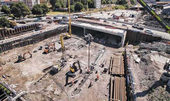
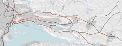
The largest bottleneck for railway traffic in Norway is in the Follo district between Oslo and Ski, a suburb of the capital city. As part of the Norwegian National Rail Administration’s plan to increase rail capacity out of Oslo, the Follo Line Project was begun in 2014 as the largest infrastructure project in Norway’s history. This project is the focus of intercity development that is planned south of Oslo, Norway’s largest city. It includes the Nordic region’s longest railway tunnel, which extends over 12.5 miles (20 kilometres).
The Follo Line Project involves a twintube tunnel that is mostly embedded in solid granite, and that will allow trains to reach a speed of 150 mph (250 kmh). Keller began serving as the subcontractor on the project in 2016, mobilizing more than 70 specialists from nine European countries for this major project using steel core piles (SCPs) for the foundation. The geotechnical challenge centered on stabilizing sensitive clay and quick clay where it transitions into hard rock along sections of the railway tunnels. To do so, Keller used a combination of dry deep soil mixing and jet grouting. Besides the development of a novel jet grouting anchor system, the subcontractor also used a backflow treatment plant to minimize the environmental impact of jet grouting — the first successful application of this approach in Norway.
The foundation work that is the focus of this article relates to Oslo’s main railway station (Oslo S). The main construction work started in 2015 and is expected to be finished within 2020 so that the railway and signaling works can start. The first train is expected to pass through the new tunnel by December 2021.
GEOLOGY
The soil in which the tunnels needed to be constructed is often characterized by different types of clay. In some parts of Norway, the clay is soft and might even be characterized as quick clay that can become unstable under stress; but in other areas, the clay is described as stiff and medium in its sensitivity. Above the clay there is typically a layer of dry crust and fill that mostly varies in thickness between 3.3 feet (one metre) to 16.4 feet (five metres), sometimes thickening up to 33 feet (10 metres). Underneath the clay, there is often a moraine layer between 3.3 feet (one metre) and 66 feet (20 metres) thick, before reaching the bedrock of diabase and syenite porphyry. In the Oslo area, there are layers of alum shale between the moraine and bedrock. This is a black shale that resembles species of rock containing pyrites (sulphur ore) and pyrrhotite (magnetic pyrites).
Quick clay in its remolded state has a shear strength of < 0.07 psi (0.5 kPa) and will be a liquid. This soil has brittle fracture properties (a considerable reduction of strength) when experiencing strains larger than strains at its maximum strength. Therefore, quick clay may cause progressive landslides, where a minor landslide evolves into a considerably larger landslide. Such landslides due to quick clay tend to occur in Norway, Sweden, Finland, Russia, Canada, and Alaska.
FOUNDATIONS WORKS
For the tunnel foundation, an SCP was chosen, which is the most executed foundation type in Scandinavia. An SCP typically has a permanent casing of 3.5 to 16 inches (90 to 406 millimetres) for corrosion protection and a centered, solid steel core of three to 12.5 inches (80 to
320 millimetres) for load transfer into the bedrock. The gap between the casing and steel core is filled with concrete or mortar to ensure double corrosion protection. With casing sizes between 14 inches (350 millimetres) and 47 inches (1,200 millimetres), the steel core is replaced with concrete that has a reinforcement cage. The main parts of an SCP are: • A permanent steel casing, drilled through soil and then into rock. • A steel core, installed with spacers over the full pile length; it is extended by using American Petroleum Institute (API) threads. • When necessary, rock-socket drilling without a casing is done instead to create a skin friction pile. • Load transfer elements, such as a head plate and tension pile application. • Grout to provide corrosion protection and load transfer.
To extend the casing, welding or threaded sleeves are used. The cores are joined by API threads and are placed in the casing with a nonconductive spacer to guarantee minimum grout coverage for corrosion protection. Depending on the bedrock quality, different socket lengths are drilled below the casing. If so, the casing is placed about 3.3 feet (one metre) into the bedrock, followed by pilot drilling into the solid rock to place the steel core and to guarantee that a good load transfer occurs, mainly by skin friction.
PILE DRILLING
In the Scandinavian subregion, a casing is often drilled into the ground using the overburden drilling eccentric (ODEX) method. When suitable for this approach, a down-the-hole (DTH) hammer, or a top hammer, is used. This is done in nonsensitive soil conditions as an efficient, economical combination to install casings. However, the air consumption necessary to power the DTH hammer for a standard pile configuration is around 20,000 L3 (20 metres) of air per minute.
Taking this air consumption into consideration, a modified drilling technique was required for the Follo Line Project to minimize the likelihood of uncontrolled pore pressure changes in sensitive clays, which were found to occur early on during piling works.
The Keller Reversible Circulation Drilling (KRCD) technique that was devel-



oped, which is water-based, requires 40 times less volume per minute to install a pile than air-powered drilling systems. This significantly impacts the risk factor for uncontrolled pore pressure changes. Therefore, all piling works at the Oslo S project were changed to the KRCD method. With this drilling technique, the environmental footprint is also improved due to the ability to use electric-powered pumps for drilling and to reuse the water from drilling because of a recycling process.
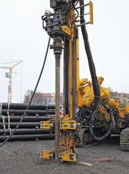
Keller developed the drilling technique during the project to minimize the influence of drilling to the surrounding soil. As the drilling fluid is reused during the process, the environmental footprint is significantly improved compared to standard drilling techniques. The KRCD technique is performed using a doublehead rotary drill rig in combination with a water-powered hammer and a backflow treatment plant in the form of a centrifuge or filter press. Casing and drill rods are rotating independently by means of rotation direction and drilling velocity. Therefore, leakage is avoided of groundwater out of the casing and into the pile or drilling fluid. If this approach were not applied, any change in the groundwater table and/or pore pressure would cause large settlements of the surrounding buildings.
As the drill bit is located around 15 inches (40 centimetres) higher than the casing shoe during drilling, the drilling debris is continuously flushed through the inner ring space between casing and drill rods. At the drill rig, a sealed connector allows measurement of the volume of backflow before the debris is treated by the filter press; the treated water is reused for flushing and powering the water hammer. With this drilling system, an overall analysis is also performed of the amount of drilling fluid input and debris output for every single pile.
In quick clay — or in very soft soil — it is important to prevent the drilling fluid, air or water of drilling to enter into the surrounding soil formation. In assessing pore pressure measurements for a piling group of 50 piles using the KRCD approach, no major changes in pore pressure were observed during and after the piling works.
According to Handbook R762E from the Norwegian Public Roads Administration, Keller’s drilling method is in line with the definition of a reversible circulation system, characterized by having the flushing fluid returned to the surface inside the casing.
In soft soil conditions, such as clay, drilling is done with the rotation of the casing. This method avoids the overcut between the casing and the drill bit (the so-called ring space). This allows all drilling debris to be transported up to the working platform through the casing, where it can be properly controlled and treated. The full-face drill bit is set at approximately 15 inches (40 centimetres) inside the casing to avoid any increase of pore water pressure and to only flush out the drilled material (to have a low water pressure for soil removal). Also, since the casing shoe is welded onto the casing, there is no overcut, which avoids leakages. The casing size is the actual drilling diameter. This technique is mainly used in sensitive soils since it is the most effective technique to avoid disturbing surrounding soil in terms of pore water overpressure or connection of different water layers.
The big advantage of this drilling technique is that a complete material flow chart can be produced for each single pile. Therefore, flow meters are mounted to measure the water used during drilling and to analyze the amount and consistency of drilling debris recycled by the backflow treatment plant.
BACKFLOW TREATMENT
At the Follo Line Project chamber filter press, units were used to separate solids from water, which was then reused for drilling.
The filter press is a very effective backflow treatment system. The hydraulic filter press itself has chamber panels equipped with filter textiles for the separation process. Due to the overpressure in the filter panels, water is squeezed out and solids accumulate in the filter chambers. As soon as the plates are filled with dewatered clay, the hydraulic piston releases its pressure, and the solid mud is ready to be discharged. The overall cycle time depends on the backflow material and its composition. The setup used at Oslo S demonstrated that each cycle can treat around 250 feet (seven metres) of drilling debris in around 25 minutes.
PILE TESTING
To verify the bedrock quality and proof the bearing capacity of the piles, static and dynamic load tests were executed (even though static load tests are uncommon in Scandinavia). The installed piles consisted of a 10.7 inches (273 millimetres) casing with a six inches (150 millimetres) solid steel core and were tested with a load of up to 112. 4 kip (500 kN). For the static load test, a settlement of 1.3 inches (34 millimetres) at a load of 112. 4

kip (500 kN) was measured, with a per- to a landfill. However, because electric pile, in combination with automating the manent settlement found of 0.8 inches versions of other machines are still being drilling parameters used for project ex(eight millimetres). developed, Keller executed the micropile ecution. l
Dynamic testing for SCPs is not stan- drilling at Oslo S using a KLEMM 807 dard as well, mainly due to their high drilling rig, with a fossil fuel-based enDominik Gächter, Dipl. Ing., is the regional bearing capacity in respect to a small cross section. A dropping height of 3.3 feet (one metre) and a weight of 24,251 pounds (11 tonnes) was necessary to gine. Based on the KRCD method being successfully applied at the Follo Line Project, manager for Keller in Norway. In the last 10 years, he has built up international experience in geotechnical engineering and analyze the system and get bearing ca- Keller is investigating automatization of contracting and leads some of the largest pacity feedback. After reviewing the pile stages in the flow chart for each single European infrastructure projects for Keller. load test results, a socket length based on the drilling speed was defined in correspondence with the drilling logs from the test piles. Further piling works were controlled by dynamic pile tests to verify the bearing capacity. The model used to analyze the dynamic testing was calibrated by the static load tests executed at the Interpipe Inc. is a steel pipe distributor of new and used structural steel pipe. We have two large stocking locations of Seamless, ERW, ONTARIO 3320 Miles Road, RR#3 Mount Hope, Ontario L0R 1WO beginning of the project. CONCLUSION The KRCD method applied with double rotary heads allowed the most sensiInterpipe Inc. is a steel pipe distributor of new and used structural steel pipe. We have two large stocking locations of Seamless, ERW, Spiralweld and DSAW pipe. Spiralweld and DSAW pipe. 3” OD – 48” OD in a variety of wall thicknesses are stocked in both locations. Interpipe Inc. is a steel pipe distributor of new and used structural steel pipe. We have several stocking locations of Seamless, ERW, Spiralweld and DSAW pipe. ONTARIO 3320 Miles Road, RR#3 Mount Hope, Ontario L0R 1WO Local: (905) 679-6999 Local: (905) 679-6999 Toll Free: (877) 468-7473 Fax: (905) 679-6544 ONTARIO 3320 Miles Road, RR#3 Mount Hope, Ontario L0R 1WO Local: (905) 679-6999 tive drilling in difficult soil conditions for the Oslo S project. Because both rotary heads worked independently, the drill bit could be positioned inside the casing to avoid any disturbance of surrounding 3” OD – 48” OD in a variety of wall thicknesses are stocked in both locations. Piling Pipe 80,000 min yield seamless pipe for Micro Piling. Piling Pipe 80,000 min yield seamless pipe for Micro Piling. Seamless and ERW pipe for Driven Piles, 3" OD – 48" OD in a variety of wall thicknesses are stocked in all three locations. Piling Pipe 80,000 min yield seamless pipe for Micro Piling. Toll Free: (877) 468-7473 Fax: (905) 679-6544 QUEBEC 805 1 ère Avenue Ville Ste. Catherine, Quebec QUEBEC 805 1 ère Avenue Ville Ste. Catherine, Quebec J5C 1C5 Toll Free: (877) 468-7473 Fax: (905) 679-6544 QUEBEC 805 1 ère Avenue Ville Ste. Catherine, Quebec soil. Based on piezometer readings obtained on the site and within 0.6 miles (one kilometre) of the project, using waSeamless and ERW pipe for Driven Piles, Screw Piles and Drill Piles. Large Diameter pipe for Driven Pile or Caissons. Screw Piles and Drill Piles. Large Diameter pipe for Driven Pile or Caissons. Seamless and ERW pipe for Driven Piles, Screw Piles and Drill Piles. Large Diameter pipe for Driven Piles or Caissons. J5C 1C5 Local: (450) 638-3320 Toll Free: (888) 514-0040 Fax: (450) 638-3340 Local: (450) 638-3320 Toll Free: (888) 514-0040 Fax: (450) 638-3340 J5C 1C5 Local: (450) 638-3320 Toll Free: (888) 514-0040 Fax: (450) 638-3340 ter as a drilling fluid significantly reduced water pressure changes. The approach also was found to reduce fluid volumes 40 times compared to air drilling. Therefore, soil inside the casing was always flushed with water to protect the casing and to avoid any soil disturbance. This minimized the risk of quick clay landslides and settlements due to pore pressure changes and ensured safe construction of foundation works.
To reduce the project’s overall environmental impact, the majority of the equipment — including the water pumps, backflow treatment plant and grout mixing plant — was powered by electricity. The backflow treatment plant also reduced Keller’s need for material transport www.interpipe.com
