10 minute read
The New Tottenham Hotspur Stadium gains recognition for engineering innovation The venue won the Supreme Award for Structural Excellence and the Award for Long Span Structures, at IStructE’s Structural Awards 2019


GAINS RECOGNITION FOR ENGINEERING INNOVATION THE NEW TOTTENHAM HOTSPUR STADIUM
The venue won the Supreme Award for Structural Excellence and the Award for Long Span Structures, at IStructE’s Structural Awards 2019.
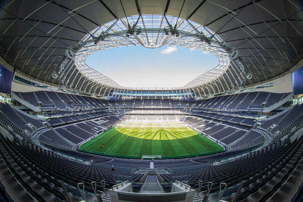
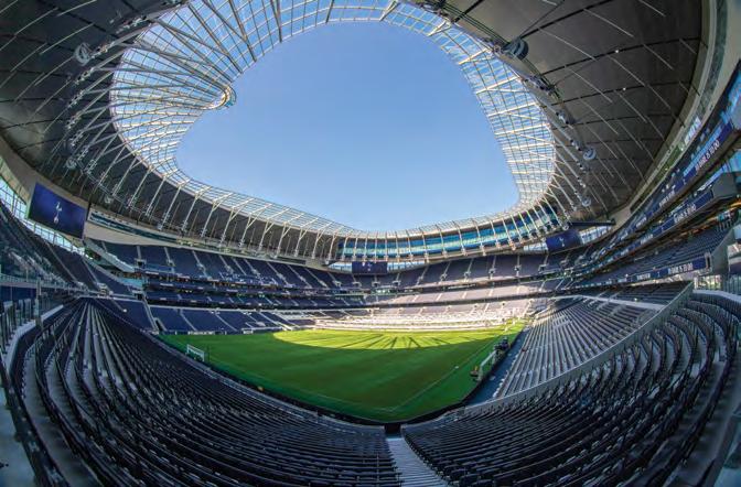
The New Tottenham Hotspur Stadium.
INTRODUCTION The New Tottenham Hotspur Stadium is the realisation of an ambitious vision from Tottenham Hotspur Football Club (Spurs), to create the best football stadium in North London, the English Premier League (EPL) and Europe, whilst replacing the club’s former home ground at White Hart Lane. With spectator capacity increased from 36,240 to 62,062 (this has since been boosted to 62,303), the new venue officially opened on 3 April 2019. Tottenham can now stage football matches, NFL (National Football League) or American football league games, and concerts, along with private events such as conferences.
FOUR MAIN OBJECTIVES Starting in 2009, Buro Happold provided multidisciplinary services, from concept through to completion. Over 230 of the firm’s consultants and engineers worked directly
The completed facade of the new stadium.
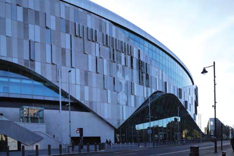
on this landmark undertaking, Populous was the architect for the project. All of Buro Happold’s work served four overarching requirements - keeping the club at Tottenham, overcoming
poor transportation links, driving investment in Tottenham and the wider community, and bringing the NFL to Tottenham. Spurs have played at White Hart Lane since 1899. The area is not only deprived but also difficult to access. However, a sense of tradition - along with the opportunity to improve life for local residents and businesses - made staying in Tottenham a priority. Overhauling existing infrastructure would be extremely time-consuming and expensive. Instead, creating a welcoming, exceptional stadium encourages fans to arrive early and stay later. This serves to smooth peak travel demand. The club chairman, Daniel Levy, wanted to make Tottenham the best place in London for the NFL. Bespoke facilities, not least of all a dedicated pitch, made this a reality. The first NFL game was played at the new stadium on 6 October 2019.
ENGINEERING CHALLENGES Key to this has been the engineering innovation, particularly the contribution of structural engineering. From sliding a 85 m by 110 m grass pitch under 17,500 people whilst controlling structural dynamics, to eliminating 40% of the columns to provide open concourses and hospitality spaces, structural engineering has played a key part in enabling what is arguably now the best football-focused, multi-use stadium in Europe. The challenge was to bring fans as close to the pitch as possible while also increasing capacity from circa 36,000 to 60,000+ seats to deliver the biggest EPL stadium in London. A key ambition was also to attract the NFL to North London by including an uncompromised American football configuration. The construction was also a key challenge, with a constrained site and a requirement to build around the existing stadium to minimise the time playing away from home.
Column-free spaces Given the requirement for a tight floor-to-floor height and the widest possible structural grid, post-tensioned (PT) concrete flat slabs were the obvious choice for the main building frame at lower levels. Steel structures were used at higher levels where spans increased further and a steel frame was used for the South Stand where construction speed was essential. The use of PT slabs has reduced the overall column numbers by 40% (circa 1,830 reduced to 1,100) with the basic grid increasing from 7.65 m x 8.5 m to 10.1 m x 11.26 m with a 325 mm thick slab in the East and West Stands. Site-won gravel was used for the lower slabs with significant cost savings and embodied carbon reduction. Screeds were eliminated with finishes applied directly to the concrete slabs or the top surface of the slabs polished to form the finish for key concourse areas. PT slabs are a well-used technique for residential buildings in London but had never been used on a stadium structure of this scale before. Buro Happold working with
Column-free spaces.

Truby Stephens and then Walsh were able to develop an efficient design to provide a high quality of finish, with clean soffits and exposed structure with inherent fire protection. This, along with the innovative polished finish technique introduced by Morrisroe have resulted in a unique and high quality concrete frame that forms the backdrop to much of the stadium interiors. In the East Stand, two further columns where omitted at Level 03 to give an overall 19.6 m x 30.3 m column-free, double-height space to facilitate a non-match day conferencing offer. This was achieved by inclined steel columns reaching up three-storeys to a steel transfer truss, one-storey deep, to provide an arched/truss hybrid. The resulting 3.2 MN lateral force is tied by additional Macalloy bars in the Level 03 slab. Enhanced by the exposed concrete frame, the new standards set by the project for both the hospitality and General Admission (GA) spaces are unprecedented. Clearly, a key outcome of creating better spaces is happier fans and as a result, more revenue for the club. The slim-line floor slabs also help fit more Gross-Internal-Floor-Area (GIFA) within the overall permitted envelope which again equates to higher revenue opportunities for the club. The polished concrete surfaces also removed a wet-trade and further programme activity from the build and greatly reduces the risk of future finishes failure - a drawback for using screeds in many other venues.
South Stand transfers and adaptability The main home end terrace, the South Stand seats 17,500 fans in creating the ‘engine room’ for a uniquely intense stadium atmosphere. This is the largest single-tier stand in the UK. To enable this feature, hospitality areas are restricted to the East and West Stands. The sliding pitch is the first in the world to have a full grass pitch that splits into three parts before sliding out of the stadium. The key engineering challenge was allowing the sliding pitch to be parked underneath the stand while controlling the structural dynamics, and provide optimum sightlines. Buro Happold had to rewrite the guidance on dynamics to make this work and verify the results with onsite testing. This key engineering innovation allows a dedicated NFL pitch to be provided 1.5 m below the first row of seating.
The sliding pitch.

South Stand plate steel trees. Image by Robert Greshoff.

The South Stand accommodates the ‘pitch pocket’, a basement recess into which the grass pitch can be retracted in three sections. This capability is fundamental in maximising functionality. As well as accommodating NFL games, it enables the stadium bowl to be easily converted into a venue for concerts and other events. To allow the three pitch trays to slide into the carpark space under the South Stand, a series of long-span transfer structures were required. Generally, these transfers are storey-height trusses embedded in the steel frame with 22.25 m outer spans and a 30.6 m central span. Two sculptural ‘tree-columns’ are then used to support the 78 m length of the back-of-bowl and act as architectural features within the cathedral-like home stand volume. The ‘trees’ weigh 262 t each and stand 26 m high, collecting 21.85 MN of gravity loading which they transfer to the piled foundations. In designing the South Stand structures, as a whole, structural dynamics was a key consideration. With a fundamental frequency well below acceptable lower limits for a route 1 analysis, significant development in route 2 analysis was required to demonstrate compliance. This involved developing a more sophisticated methodology that accounted for the overall mass and damping of both the stand self-weight and crowd. The stand was also tested to verify Buro Happold’s analysis and secure the sign-off from the local Building Control.
Roof elegance The roof design developed significantly through the duration of the project. The initial solution was a series of interconnected steel trusses - primarily a bending structure. However, concerns over temporary tower requirements for construction, and the visual impact of the structure from the key ‘sky-lounge’ hospitality spaces, prompted a design change to a light-weight cable-net roof system. This created a more slender and visually elegant light-weight structure. The initial cable-net roof design was developed by Buro Happold, with Schlaich Bergermann Partners (SBP), appointed later to finalise the design and detailing through to construction. Key developments by SBP have been the refining of the overall geometry, development of the roof cassette system and the introduction of a glass leading edge. The final design is a looped cable structure with an outer compression ring and two inner tension rings. Although the roof is clad with rigid elements - metal deck cassettes at the outer perimeter and glass at the inner edge - no horizontal bracing is used. Rather, the structure carries horizontal loads and uneven loading scenarios by geometrical stiffness only. This optimises the overall primary structural members to a minimum required size. The roof structure is a key feature of the stadium and its lightness and elegance contribute significantly to the architectural integrity and consistent visual appeal of the building. This is characterised by the quality and refinement of the details. For the outer part of the roof, individual roof cassettes (metal deck stiffened frames) are arranged in-between the cable gridlines. Each bay of roof cassettes is supported individually on specially tailored bearings to allow in-plane movements of the cable structure as well as out-of-plane differential movements and stretching and shortening of the individual cables related to the loading state. The cable-net experiences a change of geometry for each loading state - as well as during erection - and so bearings are configured to a defined off-centre erectionpre-set condition for each node to achieve the required movement allowance in the final state. The cable-net roof supports the UK’s first stadium ‘skybridge’, providing hospitality space with incredible views of the pitch from above the North Stand. The structural design and the detailing required to allow for the movements of the cable-net have been very challenging. The solution was to create a series of individual boxes between radial roof cables, allowing the bridge to articulate with the roof movements. To prove the in-service movements of the roof were going to be acceptable to the users of the ‘sky-bridge’, Buro Happold specified a series of tests at the University of Southampton’s 6-axis dynamics test facility. Time-histories of varying wind-induced movements of the roof were fed in to the simulator and both design team members and key stakeholders from the client team were invited to experience the predicted effect. This gave the team confidence that the final space would be suitable for intermittent use.
The cable-net roof.
Key to delivering the cable-net structure has been the need to utilise construction and manufacturing efficiencies. Although the cable-net has different geometries on each of the 54 grids, an efficient way was found to allow the use of more elegant cast cable nodes. All 54 nodes are based on only eight different basic cast geometries. This was achieved by combining four varying mould geometries for the main cast bodies which connect the set of six cables of the lower tension ring together with four mould types for attachment of the radial cable lugs. These eight types were then individually machined to suit the individual locations of each node. The glass inner edge provides a level of refinement and quality to the roof. In contrast to other glazed cantilever roofs supported on cable structures, the glass supporting frames are placed on top of the radial cantilevers. The result is a significantly reduced visible width of the main support line, with the radial elements of the glass support frame aligned with the primary supporting cantilever producing a single, clean profile.
PROJECT CREDITS Project New Tottenham Hotspur Stadium, London, UK Duration 2009-2019 Client Tottenham Hotspur Football Club Architect Populous Provision of multidisciplinary services Buro Happold (Visualisation, Risk and resilience, Security and technology, Structural engineering, Sustainability, Transport and mobility, Waste management, Building services engineering (MEP), Energy consulting, Environmental consultancy, Facade engineering, Fire engineering, Ground engineering, Infrastructure, Inclusive design, Lighting design)

All images by Buro Happold unless otherwise stated


