28 minute read
Design economics of multi-purpose offshore wind farms The conventional development concept and an alternative approach are presented and compared


by Bob L Y Cheung, Bob Cheung Offshore Consultants, Singapore
The conventional development concept and an alternative approach are presented and compared.
INTRODUCTION
Climate change is one of the most urgent challenges facing the world today and renewable energy will certainly replace fossil fuels in the near future. Several rich nations, mostly in Western Europe, have set net-zero targets before 2050 and more countries are set to follow, depending on their financial resources. These rich nations have chosen wind energy, especially offshore wind, as the most suitable renewable energy for the transition to a net-zero carbon future. The selection is reasonable based on their situations and locations, yet it is far from certain if developing countries will follow the same transition route as their developed peers due to high cost and other reasons. Presently, these rich nations are moving swiftly in the development - several huge offshore wind farms will be operational in the next two to three years. The rest of the world, on the other hand, is hardly moving at all, with the exception of China. Energy transition is a global concern and we have to find ways to bring down the high cost of Offshore Wind Farms (OWFs) so that more countries can participate. In some countries, solar energy may be a cheaper choice. The purpose of this article is to analyse the cost components of a typical OWF project in Europe and question both the need for such high costs and the suitability of the present development concept for other countries, and then propose an alternative approach to reduce the lifetime OWF cost. In short, the proposed concept is a poor-man’s solution to a super expensive OWF project.
REVIEW OF THE ‘STANDARD’ OWF DEVELOPMENT CONCEPT
OWF development is similar to offshore oil and gas production. Before a site is selected, various site investigations and feasibility studies would have been conducted to assess the suitability of the site. The studies may cover wind flow patterns, soil investigations, environmental impact, field layout, turbine and cable selection, onshore and offshore substations etc. The developers will carefully look at the costs for the set-up, design, installation, operation, maintenance and decommissioning of the project, to make sure it is profitable. They would be more interested in the Levelized Cost of Energy (LCOE) of the project for comparison, but this is not our objective. We are only interested in the total cost reduction from a technical viewpoint. In summary, the ‘standard’ development concept calls for installing all the turbines using either monopiles or jackets as foundation. The preference is for a jack-up vessel to install the turbines, as it can provide a more stable working platform for lifting. Once completed, cables will run from the nacelle down the turbine tower to the transition piece and the monopile via a J-tube to the seabed. If it is a jacket foundation, the cables will run from the outlet at the bottom of the turbine tower into the J-tube, then to the sea floor. The infield array cable will then be laid using a cable-lay installation vessel to connect it to a substation or other turbines. The cables will be buried in 2 m to 3 m below the seabed. This is accomplished using cable burial equipment and a cable plough operated from a special vessel. The whole operation is monitored by remotely operated equipment. A substation is a special offshore platform, usually installed by a standard derrick barge. The export cable is laid from the substation to a landfall location onshore, then to the onshore substation. The whole operation may take a longer time depending on the distance, but is not difficult, except the shore-approach and a few cable crossings. After turbine installation, the developer will need special vessels to operate and maintain the farm. This may include crew transfer vessels (CTVs), service operation vessels (SOVs) and supply boats. In some cases, helicopter services will also be needed to transfer maintenance staff to the nacelle, in poor weather. If major repair or replacement is needed during operation, heavy lift or jack-up vessels may have to be recalled to perform the task. An OWF is an immensely expensive undertaking and the only consolation is that the energy source is free, albeit rather intermittent.
SUMMARY OF COSTLY HARDWARE AND ACTIVITIES OF A TYPICAL NORTH SEA OWF DEVELOPMENT
Compared to offshore oil and gas production, an OWF is based on a simple and straightforward technology. There is no need to consider well-stream chemical composition, separation, storage and transportation. In fact, there are far more expensive and complicated processing vessels
Hardware (Monopiles, Transition Pieces, Wind Turbines, Export & Array Cables, and Substations). Jacket foundations similar Installation (2-3 years) All items.
Operation (25 years at GBP 30 m per year)
Maintenance (25 years at GBP 60 m per year)
Decommissioning (All items)
GBP 1,700 m
GBP 450 m GBP 750 m
GBP 1,500 m
GBP 400 m
TOTAL ∑ GBP 4,800 m
Table 1: Total cost summary (2019) for the OWF project example.
on an oil and gas production platform than everything inside a nacelle, the tower and the substation. One big production platform can cost easily more than 60 to 70 10 MW wind turbines. However, a wind farm will need a lot of turbines. Intuitively, one would expect a medium size OWF should cost less than an oil field development project, but this is not the case. In the long run, an OWF may be highly competitive after taking into account the free energy source, the cost of carbon emitted by fossil fuels and the environmental impact to the world. But, in the short term, very few countries can afford the billions of dollars needed to develop OWFs. This article will address this concern. Let us consider the example of an OWF project in the North Sea [Ref 1]. The project is a 1000 MW wind farm with 100 wind turbines. The site has a 30 m (100 ft) water depth and is 60 km from shore. The design life is assumed to be 25 years. Cost figures are in millions of British Pounds (GBP). Based on our offshore experience, we have re-estimated the costs and grouped them into five categories, as shown in Table 1. We did not, however, include the PMT cost.
Considerations
• Different assumptions can lead to different results.
Hence, no attempt is made to verify or discuss each entry. There are many factors affecting each number. We will only look at the relative magnitude of the cost of each item and the overall project cost implication. • We will look at the installation, operation and maintenance costs only [Ref 2]. • Transition pieces will be combined with monopiles to yield a total cost, which makes it more expensive than the jacket option. • The installation cost for the export cable is assumed to be 25% of the array cable installation cost. Assuming no cable crossings, the cable lay-rate for the export cable will be fast.
Equipment day rates
For discussion, we shall also provide the following equipment day-rates based on North Sea usage. These rates are subject to market condition and huge fluctuation is expected.
EQUIPMENT
Heavy Lift Derrick Barge
Jack-up Turbine Installation Vessel
Piling Hammers & Grouting equipment for Foundation Installation
Cable-lay Vessel
Cable Burial Vessel with Plough Sleds, Water Jets and ROV.
Service Operation Vessel (SOV) with Facilities
Crew Transfer Vessel (CTV) without Facilities
DAY RATE
GBP 180,000
GBP 150,000
GBP 50,000
GBP 90,000 GBP 90,000 GBP 30,000 GBP 3,000
Table 2: European equipment day-rates (2019) in the North Sea.
QUESTIONS ON THE HIGH COSTS FOR AN OWF AND POSSIBLE ALTERNATIVES
Is monopile foundation cheaper and better than jacket foundation?
If we consider the monopile and the transition piece as one unit, it is more expensive than a jacket. But this is not a complete answer. We should appreciate the full extent of this question by looking into the consequential cost implication of each option, monopile or jacket, for operation over the whole lifetime. There are many potential wear-and-tear problems in a wind turbine [Ref 3], which will greatly affect the Operation and Maintenance (O&M) costs. For example, inside the nacelle, there are rotating machines running almost on a 24/7 basis, to generate electricity. The hub connecting the three blades will rotate day and night and the yaw table will turn frequently to line up the nacelle with the wind direction. This kind of unavoidable nonending motions will cause mechanical wear-and-tear. As recently reported, turbine blades also have wearand-tear problems. Any repair or replacement will be expensive. A jack-up installation vessel can cost GBP 150,000 per day, excluding mobilisation and demobilisation. An SOV, supporting maintenance engineers, can demand GBP 30,000 per day and a CTV or a helicopter may be needed to get the engineers to board the turbine in poor weather. For a 5- to 6-day repair job, the total rental cost of the vessels could be GBP 1 m.
In the project example, there are 100 wind turbines and one can appreciate the cost implication if something fails. In any case, many failures will most likely happen in the course of the lifetime. The SCADA system in an OWF can provide early warning for possible malfunctions, so that repairs can be carried out earlier, but it cannot prevent failures. Getting replacements will take time and the loss of production is also a major concern. One way to mitigate the problems and reduce the frequency of repairs and replacements is to design a near-rigid foundation to reduce the added foundation movements impacting the turbine operation. Misalignment due to excessive foundation movements can aggregate wear-and-tear. In an OWF, the usual choice of foundation is either a monopile or a jacket. Structurally, a free-standing pile in water will never stand still even under a small sea-state. From experience, a 36inch pile can sway 24 inches, side-by-side, under a small wave in a water depth of 100 ft. Large foundation sway motion on a 24/7 basis is not desirable in wind turbine operation. To achieve a near-rigid foundation condition, a monopile should have a large section modulus, leading to a large diameter pile. In the project example, it can be more than 10 m (about 33 ft). To avoid local buckling, the D/t requirement will make the wall thickness more than 4 inches to 5 inches. That is why a monopile can weigh over 1,000 t. Large diameter objects will attract a higher wave load and the design is more complicated, as the linear wave theory is no longer applicable. A wind turbine also has a verticality criterion. The permitted deviation from the vertical is small. Clearly this requirement cannot be met when driving a 33 ft diameter pile using only one pile-guide attached to the side of the jack-up installation barge and the size of the hammer is much smaller than the monopile diameter. To overcome the vertical alignment problem as well as other installation issues, many contractors introduce an oversized transition piece. The transition piece also provides other functions such as acting as a mating flange to receive the turbine tower, an access ladder to the tower, a working platform, J-tube, and anodes for cathodic protection. The other issue is that driving a monopile with everything already attached is asking for trouble. The total weight can reach over 500 t and the whole foundation system can be more than 1,500 t. Many developers claim that the monopile/transition system provides the best economic solution. This assertion may be correct in Europe, but highly questionable in Asia. Large diameter tubular fabrication, such as for monopiles or transition pieces, is a simple process which involves bending lots of very thick plates and welding them up using special welding procedures. This is more suitable for European yards which have high labour costs. However, a jacket structure may be a cheaper option in Asia. A jacket can be designed to have high rigidity with a lot less steel. For example, for a small jacket in shallow water, with no boat-landing, no conductor guides and framings, no risers, no sumps, no J-tube and only a small number of anodes and few small mud-mats, the steel tonnage is likely to be less than 500 t, excluding skirt piles, and the jacket fabrication man-hours should be about 50 man-hours per ton. Welding thin walled tubes is much easier and the labour cost in Asia is low including for qualified welders. Levelling can be done using standard offshore installation procedures. A jacket transition piece is no bigger than the pile or jacket leg. The turbine tower can be fitted on top of the jacket and shim plates can be added to achieve more precise levelling. For installation, a small sized, conventional derrick barge with a small crew, which can cost less than USD 100,000 per day, can do the job. The cost would be even lower, if we use a sheer-leg installation barge. For procurement, most jacket members, except legs and piles, can be ordered directly from a mill and there is no need for rolling in the yard. Some developers do use jacket foundations, but they prefer a subsea piling-template, perhaps due to the limited weather window in the North Sea, which will make the jacket slimmer. This is not ideal for reducing foundation swaying motions. A possible solution is shown in Figure 1. In conclusion, a jacket foundation is a cheaper and better option, and the biggest cost-saving will come from fewer repairs and replacements due to less wear-and-tear problems in the years to come.
Is a jack-up installation vessel the best option for turbine installation?
A wind turbine is a gigantic yet light structure in comparison with an offshore platform. The overall diameter can be more than 500 ft and the blade can be over 250 ft long. The tower can be more than 350 ft tall. Due to the size, developers prefer to install the turbine piece-by-piece offshore. The procedure is to first install the tower, then the nacelle and followed by the hub and blades. All the connections are usually bolted. Trying to assemble the turbine piece-by-piece with a conventional single-hull derrick barge in open sea is almost impossible due to ship motions. The other option is to use a jack-up installation vessel, which is much more stable once jacked up out of the water. Therefore, some contractors are willing to invest over USD 500 m to build a jack-up installation vessel with a crane, good only for 2,000 t or less. Are there cheaper alternatives? Operating a jack-up is usually time-consuming, due to safety concerns. First, a site survey is needed to ensure the site is clear of boulders and the soil is strong enough to support the spud-cans. Second, after settling down, a pre-load test is carried out to check the expected maximum load. This is to guard against the spud-can punch-through problem. Insurance companies usually call for this safety procedure and the whole operation may take 24 hours or more. After installation, the jack-up will follow another safety procedure to retrieve the legs and move to other
turbine locations. Every movement will take time and the cost can add up exponentially. If one were to use a conventional derrick barge, it would be much quicker to drop all the anchor lines and load test the holding power of each line. The whole operation can take 6 to 8 hours in shallow water, and no site survey of the bottom is needed at all the locations. Now, the question is how to pre-assemble the whole turbine before loadout and how to safely install it using a cheap derrick barge. We will tackle this problem in a later section.
Why is an array cable so expensive to install and why does it fail so easily?
An array cable can cost over USD 300,000 per km and an export cable, carrying higher voltage, can command almost USD 1 m per km [Ref 4]. They are specially reinforced subsea cables. The cost of an export cable depends on the distance from the substation to shore and the voltage it carries. An infield array cable, usually 66 KV nowadays, is smaller and cheaper. One thing to take note is that cable failure is a major concern among all the insurance companies [Ref 5, 6 and 7]. The failure may arise from installation errors due to weather conditions and the lifetime exposure to wave and current forces in certain sections of the unprotected cable. Although many contractors have invested large sums of money to build special cable-lay vessels to do the jobs, problems persist, especially in array cables. In a wind farm, every array cable must go down the turbine tower to the seabed via a J-tube, and then buried in 2 to 3 m below the sea floor. A J-tube usually ends a few metres above the sea floor for obvious reasons, leaving the array cable exposed to small wave loads before touch down. There are 100 turbines in the project example and the chances of installation errors and wave load exposure could be substantial. An array cable is small and flexible, and the bend-radius rule will limit the cable lay-stress. Any vessel movement can easily break the bend-radius rule and cause cable damage. In this project, an array cable will enter and leave the J-tube mouths no less than 200 times, and cable damage is a real possibility. If failure occurs during operation, it would be costly to remove the failed cable and insert a new one into the J-tube and cable burial is another concern. This expenditure for repair or replacement is not allowed for in the cost summary (Table 1), as no one can predict how many repairs or replacements will occur during the lifetime. The possible alternative is to replace subsea array cables with surface array cables, which will solve many problems. We will discuss this in a later section.
How to cut operation and maintenance costs?
For a lifetime of 25 years, the operation cost is assumed to be GBP 750 m and maintenance cost is GBP 1,500 m, so the total cost is GBP 2,250 m. This represents a regular O&M expenditure without major repairs and replacements. If the repair or replacement is inside the nacelle, we have to use a jack-up or a helicopter to transfer the equipment from the top. A jack-up costs GBP 150,000 per day and the helicopter will cost more. Therefore it is imperative to reduce wear-and-tear problems in all the rotating machines. This means that a jacket is a better choice. Cost saving will be apparent during maintenance. If failure occurs in the array cables, the repair cost could be much higher. Therefore, bringing all subsea array cables out of the water is a good moneysaving strategy. During regular inspections or routine repair jobs, one will need a CTV or an SOV, which can cost GBP 30,000 per day. There are 100 turbines to be inspected every few years and the total bill could be substantial. However, the whole O&M cost can be greatly reduced if workers and inspectors can go from turbine to turbine on the connecting bridges and carry out simple repairs above water. Array cables need not be subsea grade anymore. We will explain this option in a later section.
THE PROPOSED NEW DEVELOPMENT CONCEPT
Implementing an OWF project is a highly expensive and capital intensive endeavour, and many developers are working hard to bring down its cost by going further out in the sea and using floating structures with very large turbines. This could be a solution in the future if new turbines can be designed to operate with less wear and tear on a floating structure. We should also understand that installing deep water cables is not a simple task. However, many developers have yet to fully appreciate the escalating cost of building many new and special vessels to service the floating wind farm industry. Up till 2020, total investment in new vessels already ran into billions of dollars and much more will be needed for floating wind farms in the future. For less well-off countries, they should consider the cheapest option, that is, shallow water OWFs. We aim at a smaller investment that can still provide reasonable electricity generation.
SITE SELECTION
The concept of a floating wind farm with very large turbines may be a possible solution in the future. However, we are of the opinion that a near-shore wind farm could be an equally attractive option with lower lifetime cost and fewer unexpected cost over-run factors, albeit with a smaller energy output. We propose the selected site, if available, should be about 30 km to 40 km from shore in water depths less than 100 ft. This will cut down the cost of the export cable, both in terms of the material and installation. In times of emergency, the maintenance team will be able to respond much quicker. The most important consideration is the saving in O&M expenses during the designed lifetime.
CHOICE OF FOUNDATION
To reduce wear-and-tear, a jacket foundation is the best choice and the operation and maintenance cost, as explained earlier, could be lower than for a monopile/ transition piece combination, in the long run. The
Figure 1: Typical jacket with two cantilevers along the long axis, serving as bridge landing pads.
required steel tonnage is about 500 t, excluding skirt piles, whereas the monopile system needs 1500 t. A piling template should be avoided and the jacket should be designed using skirt piles to provide a larger footprint and greater rigidity. A typical jacket is shown in Figure 1. The jacket is a simple skeleton structure without any typical oil platform features such as conductors, risers, J-tube and grout lines. Therefore, 500 t is a good estimate of the tonnage for a shallow water jacket. The design is based on the environmental forces with a 100-year return period, but the turbine will long be cut-off at a much lower wind speed, hence wind load on the turbine is smaller. In fact, wave load is much bigger than wind load. Installation is no issue since there are many small size derrick barges available in Asia. If weather permits, a sheer-leg lifting vessel can also install the jacket. One can easily find sheer-leg vessels in Singapore, Batam, Malaysia, Thailand, Vietnam, Korea and China. The capacity is from 500 t to 5000 t and the day rate can be a lot lower than for a derrick barge. Of course, a derrick barge has more facilities on board but needs more people to operate it.
METHOD OF INSTALLATION OF TURBINE
In the project example, we estimated it will take seven days to install one turbine if we go for the piece-by-piece installation method. It will take one day to set up the jack-up installation barge. The installation vessel cannot hold so many monopiles, transition pieces and blades. So, many of the turbine components will have to be transported on different material barges from the yard to the farm site and it will take a few hours to cut all the tie-down members before lifting, and before piecemeal offshore assembly can begin. It is not safe to pre-cut all the tie-downs and wait for your turn for lifting.
Figure 3: Typical small wellhead jacket in Southeast Asia.
Alternatively, the vessel can return to the base to restock new turbines, but many days will be wasted. This is not an efficient operation. To cut down the installation time, we propose to cut up the turbine tower into two pieces. The bottom piece will go out with the jacket for installation. The top piece together with the nacelle and blades will be pre-assembled in the yard and the whole structure will be sitting on a specially designed support frame with a dummy tower leg prior to loadout. After arrival on site, the upper turbine section will be lifted by a derrick barge and stabbed into the lower section of the tower leg. This operation is not easy to perform and a carefully prepared execution plan is needed to do the job. The turbine support frames will be reused for the next installation. If this can be done and combined with an efficient logistics system, then the cost could be slashed by a big margin.
SURFACE ARRAY CABLES
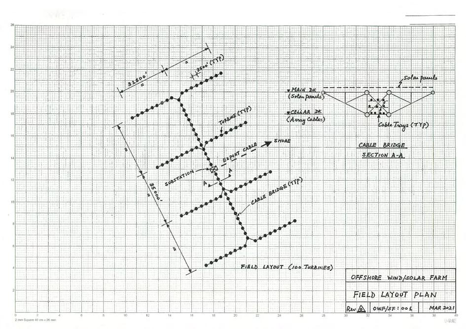
As explained in the previous section, subsea array cables do suffer a lot of failure, for a number of reasons. Hence, insurance companies are often reluctant to provide cover at a reasonable premium. A possible solution to overcome the problem is to connect all the turbines by a series of bridges and put all the array cables on it. This will get rid of all the subsea array cables and replace them by surface cables at a much lower cost. The biggest concern is ascertaining the cost of building the bridges. We can provide the following answers: • If the bridge corridor is designed to serve two objectives - serving a wind farm and a solar farm - then the cost can be split into two parts accordingly. The bridge shall have two levels. The main deck level is used for a solar farm [Ref 8] to generate electricity.
Assuming wind turbines are set at a separation of seven times the diameter, the total distance could be 7 x 500 ft x 99 = 346,500 ft. If the width is 100 ft, then the total usable area is ≈ 34,650,000 ft² (3,219,000 m²), which can be used for solar panels.
The cellar deck level of the bridge can be used to run the surface array cables. To facilitate installation and maintenance work, all the turbines can be arranged in several large U shaped formats as this configuration will allow the installation vessel to approach the turbines from both sides without crossing the connecting bridges (Figure 2). • The steel tonnage required for the bridges and the intermediate bridge support jackets could be over 200,000 t. Where do we find the steel at a low cost?
There are more than 1,000 small wellhead platforms waiting to be decommissioned in Southeast Asia alone. Some of the decommissioned materials can be re-used. A typical wellhead jacket (Figure 3) is usually in a water depth between 100 ft to 350 ft, and weighs from 1,000 t to 4,000 t. In offshore Thailand, you can find over 500 old platforms waiting to be decommissioned, yielding a minimum total jacket tonnage of 500,000 t, and some of which can be used for bridge construction. The reasoning is simple. In Southeast Asia, there are many marginal fields which usually produce less than 15,000 bpd of oil. When oil is at USD 50 per barrel, the revenue can be 15,000 x 50 x 350 x 5 = USD 1,313 m for the first five years. Then production will usually decline very quickly. Fifteen years ago, it needed less than USD 25 m to put a wellhead platform offshore, so the investment return was very promising. When the oil price drops to USD 20 per barrel and the production drops to 3000 bpd or less, it is no longer attractive to the small independent oil companies and decommissioning may be a better choice. Normally, a platform is designed for 20 to 25 years. So, when production ceases after 10 years, there should be 10 more years left in the steel if not removed. When a platform was designed for deeper water and a much bigger 100-year wave, all the tubulars should be bigger and thicker. If a certification authority can re-certify the material, then the selected steel can be re-used for building the wind farm bridges and the bridge supporting jackets. In fact, the available used tubulars are much bigger than what we need in the cable bridge design. We have over 1,000 old jackets to choose from and it will reduce the overall material cost in the project. Since oil companies are required by law in respective countries to remove these abandoned platforms, the market value should be minimal. The OWF developer can save lots of money in building a solar farm and a wind farm together. There is no technical reason why we cannot re-use the old jacket steels, especially, if a 20-year-old tanker is allowed to be converted into a new Floating Production Storage and Offloading (FPSO) unit, lasting for another 20 to 30 years. The big saving will come from array cable installation and the O&M cost during the design lifetime.
EXPORT CABLES
Since the site is close to shore, the cost is lower. The cable will go down the J-tube only once, and then go directly to shore. Therefore, the possibility of damage is small. In fact, there are a number of long distance subsea cables already in operation in many oil fields around the world.
OPERATION AND MAINTENANCE SERVICES
In this project example, the yearly O&M cost is assumed to be GBP 90 m per year. For a life span of 25 years, it will add up to GBP 2,250 m. On a yearly basis, GBP 30 m will be for operation and GBP 60 m for maintenance. The operation cost has to cover both onshore and offshore supporting functions. The onshore control room needs to be manned 24/7, to monitor the health of all the turbines, cables and substation. Therefore, one can assume the GBP 30 m cannot be cut and we should investigate the maintenance cost. In this project example, there are 100 turbines and the maintenance cost per turbine per year is only GBP 600,000. When we add up the cost of CTV, SOV and cost of supporting staff, this amount is reasonable. However, whenever there is a failure in the array cable or problems in the nacelle, we may need the service of a jack-up vessel to reach the top, and then GBP 60 m may not be enough to cover the cost of repairs and replacements as well as regular maintenance costs of all the 100 turbines in a whole year. Therefore, O&M must be considered very carefully at the early stage of an OWF development.
CONCLUSION
Based on the above analysis, it is possible to develop a poor-man’s wind farm at a much lower cost and with considerably fewer cost over-run factors. No one can predict the number of failures in an offshore wind farm in a lifetime. The bridge corridor can greatly reduce maintenance cost. The use of decommissioned jackets can cut down the cost of a solar farm. We can also relocate some of the SCADA functions to a substation offshore since we can now get to the problem turbine quickly, without support vessels and we do not have to worry about the downtime due to the weather. We can also use more turbines to increase the output, if desired. Other major cost reductions could come from the following: • Redesigning of the turbine tower to make it lighter. • Total redesign of the wind turbine installation vessel, to make it much cheaper to fabricate and capable of installing many turbines in a short time, in one mobilisation, before returning to base.
REFERENCES:
[1] BVG Associates, The Crown Estate and the Offshore Renewable Energy Catapult (2019): ‘Guide to an Offshore Wind Farm. Updated and Extended’. [2] Lacol-Arantegu et al (2018): ‘Offshore Wind Installation: Analysing the evidence behind improvements in installation time’, Renewable and Sustainable Energy Reviews, 92(2018), 133-145. [3] Sheng S and Veers P (2011): ‘Wind Turbine Drivetrain Condition Monitoring - An Overview’. Mechanical Failure Prevention Group: Applied Systems Health Management Conference 2011, May 10-12, Paper no NREL/CP-5000-50698. [4] Gonzales-Rodriguez A G (2017): ‘Review of Offshore Wind Farm Cost Components’, Journal: Energy for Sustainable Development, Vol 37, 10-19. [5] Strang-Moran C (2018): ‘Subsea Cable Management: Failure Trending for Offshore Wind’, Offshore Renewable Energy Catapult, Glasgow, UK. [6] Strang-Moran C (2020): ‘Subsea Cable Management: Failure Trending for Offshore Wing’, European Academy of Wind Energy (EAWE), Wind-Energy Science Discussions, March 2020. [7] Warnock J, McMillan D, Pilgrim J and Shenton S (2019): ‘Failure Rates of Offshore Wind Transmission Systems’, Energies 2019,12,2682, 1-12. [8] Cheung Bob L Y (2020): ‘A Realistic Design Option for Large Scale Renewable Energy Generation’, ‘The Singapore Engineer’, May 2020, 12-15, IES. (More information can be obtained by emailing bob.cheung@ rocketmail.com)
FLOATING WIND POWER GENERATION FOR OFFSHORE OIL AND GLASS PLATFORMS
In late 2019, Siemens Gamesa announced that it had received an order from Equinor to equip the Hywind Tampen floating wind power plant with 11 SG 8.0167 DD turbines. To be installed off Norway, the Hywind Tampen is said to be the world’s largest floating wind power plant and the first floating power plant to power offshore oil and gas platforms. Scheduled to be commissioned in late 2022, Hywind Tampen will have a total capacity of 88 MW and will be located some 140 km from shore in an area with water depths of 260 m to 300 m, between the Snorre and Gullfaks oil and gas platforms. Specifically, this wind power plant will be capable of meeting about 35% of the annual power demand of the Snorre and Gullfaks platforms. By reducing the use of gas turbines on the fields, the project helps cut CO2 emissions by more than 200,000 tons per year. The floating foundations in the Hywind Tampen project are ballast-stabilised and anchored to the seabed with mooring lines. With their lightweight nacelles, Siemens Gamesa large direct drive wind turbines are particularly suited for floating foundations. The partnership between Siemens Gamesa and Equinor dates back to 2009, when the world’s first full-scale floating wind turbine project, Hywind Demo, was successfully installed in Norway. This initiative was followed in 2017 by the 30 MW Hywind Scotland floating wind power plant.