29 minute read
Innovative design and materials for an institutional building


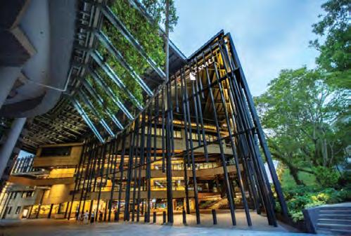
Singapore Management University (SMU) Connexion received the BCA Design and Engineering Safety Award 2020 as well as the IES Prestigious Engineering Achievement Award 2020.
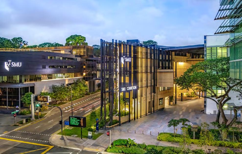
Overview of the completed SMU Connexion.
INTRODUCTION
SMU Connexion (SMUC) is an institutional development comprising a five-storey teaching block and a two-storey link building. It is a new addition to the Singapore Management University (SMU) City Campus, that supports experiential learning through real-world projects and cultivates innovation and entrepreneurship. The project sets out to fulfil four key design goals, namely encourage experimentation, enable 24/7 learning, engage the city, and embrace new sustainability initiatives. The development sits on a tight site of only about 3,544 m2 , with no direct vehicular entrance nor access. The site was partly occupied by the old National Library which had since been demolished. The new building will also provide direct connectivity and linkage to the existing SMU School of Accountancy and School of Law, over Fort Canning Link. The 8565.94 m2 GFA (Gross Floor Area) space includes active learning classrooms, brainstorming hubs, collaborative zones, integrated learning studios, makerspace, student lounges, cafeteria and incubation spaces for start-ups. For maximum flexibility, the building has open floor plates, with minimal fixed walls that can be adapted
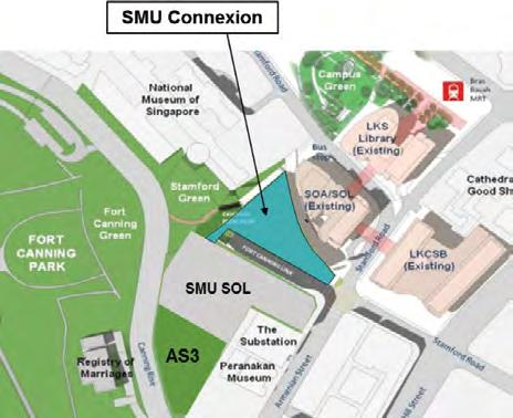
to accommodate new learning modalities in the future. Learning spaces will be defined through creative use of furniture to achieve a sense of openness and transparency. SMUC is designed to meet the Building and Construction Authority (BCA) Green Mark Platinum certification and the international WELL Building Standard. It also holds the distinction of being the city centre’s first large-scale Mass Engineered Timber (MET) development and an on-site net zero energy building, with its own power generated from a photovoltaic system. Other Green features and technologies include advanced passive displacement cooling, smart LED lighting and predictive smart building control systems. The project was tendered out in a single package with a contract completion period of only 15 months. This included the installation of foundation piles, the main building works, the construction of the Link Building over the busy 3-lane Fort Canning Link and the Additions and Alteration works to the School of Accountancy. The project is acknowledged as an example for the industry, showcasing the adoption of DfMA principles and the use of innovative structural systems, advanced construction materials (Cross Laminated Timber), modular M&E systems design and a prefabricated facade, for fast-track construction, buildability and productivity improvement. It has also incorporated several green and energy-efficient technologies to become an on-site net zero energy building.
STRUCTURAL DESIGN PROCESSES AND SOLUTIONS EMPHASISING SAFETY
The main technical challenges in the design and construction of SMUC were: • Creation of an iconic new teaching block with connectivity to the SMU School of Law and School of Accountancy. • Close proximity to surrounding buildings and services. • Construction of the Link Building over the existing Fort
Canning Link. • Low floor-to-floor height due to tight AMSL (Above
Mean Sea Level) control. • Fast-track construction programme of only 15 months. • Presence of critical ‘live’ underground services below and adjacent to the site, whose diversion was not a feasible option due to their importance, site constraints and time. • Fire safety authority compliances and product testing challenges, as this is a newly-adopted methodology in the local context. • Construction in a dense city centre. • Extremely constrained site and limited access. Construction safety and risk management were key considerations during the design process. In addition to the inherent challenges, the development was also designed to be SMU’s first on-site net zero energy building, being self-sustainable with its own power generated from a photovoltaic system located within the same premises. Given the challenges, the design had to be highly buildable, taking into consideration the access and logistical constraints on site and the fast-track programme to complete the building. The concepts and basic principles of Design for Manufacturing and Assembly (DfMA) were adopted and implemented for all trades where possible - Architectural, Structural and M&E.
Innovative structural system
The superstructure comprises an innovative hybrid SteelCross Laminated Timber (CLT) slab system. The frames of the building are erected in structural steel, while the slab is in CLT. The adoption of this hybrid system is a first-ofits-kind in Singapore. The structural system adopted offered the following advantages: • Structural steel frames offer greater flexibility especially for long span structures. • CLT slabs provide an alternative to composite steel decking but without the need for any concrete topping. • A hybrid of steel and CLT offers a super lightweight structure, resulting in savings to foundations of between 20% to 40%, compared to composite steel and conventional concrete systems. • Prefabrication of frames and slabs can be done fully off-site, for better quality control and workmanship. • Substantial reduction of overall site concreting. • Better adaptability for future-proofing. • High speed of construction and ease of erection and fixing into position. • Reduction in on-site labour. • Improvement in productivity and buildability. • Shorter construction period. • Pleasing aesthetics with the integration of the structural system and the M&E services expressed as part of the architecture and interior design. One of the key benefits with this hybrid system was the substantial reduction of in-situ concreting. As the site was very small, being adjacent to a busy road junction and without any permanent vehicular access, the adoption of this system ensured minimum disruption to both pedestrian and vehicular traffic. The structural steel frames comprise circular tubes for the columns and universal beams for the floor elements. As the steel frames would mainly be exposed and expressed architecturally, the sizes, shapes, configuration and connection details had to be worked out closely with the Architect, to achieve their design intent. To further enhance productivity and buildability, the steel members were prefabricated into modular frames off-site. The whole length of the column was divided and fabricated in two segments - from L1 to L4 and from L4 to the roof.
The connecting beams at every floor level were welded to the column in the factory, as short stubs, to form a modular frame. The column frames were erected from the 1st storey. Guy wires were used to stabilise the columns temporarily during setting out and alignment checks. Once the frames were stabilised with the installation of the 2nd storey floor beams to form a bay, the guy wires were released. The frames were designed to be self-supporting, thereby avoiding the need for temporary props or falsework during installation and enabling an uninterrupted and smooth erection sequence. This fabrication and erection strategy was repeated for all the building columns and beams. The dimensions of the frames were also engineered to facilitate easy transportation, storage and erection. The end result was the achievement of standardised and repetitive steel frames that facilitated simple and swift erection on site. The remaining parts of the beams were then connected on-site to the frames, using bolted connections, as the floors were progressively erected. The benefits of using bolted connections are as follows: • The process is easy and simple. • It enables faster erection and construction, compared to welding which requires a more elaborate set of QA/
QC and testing of weld quality. • It facilitates the use of engineered timber. The CLT slab was designed to perform two functions: • To support gravity loads and transfer these to the supporting beams. • To act as a horizontal diaphragm that transfers lateral wind and notional loads to the core and shear walls. The typical CLT slab consists of seven lamellas glued together to make up a total thickness of 220 mm. A polyurethane adhesive was specified as it is formaldehyde-free and more sustainable in the long term. The 3rd storey of the Link Building was constructed with a thinner floor system made from 140 mm thick CLT panels. The CLT panels were typically connected to each other and to the top flanges of the supporting beams by wood screws. Special connections to the cores and shear walls were detailed as these were required to transmit wind and notional forces. The CLT slab was designed for a fire rating of 1 hour. Fire protection of the slab is achieved through the charring depth of the CLT. The design of the CLT slab took into consideration the effects of charring during a fire. Likewise, anchor bolts and fixtures to suspend services from the underside of the CLT slab had also considered the charring depth in the design of the embedment depth. Fire protection of the steel structure is typically achieved by intumescent paint.
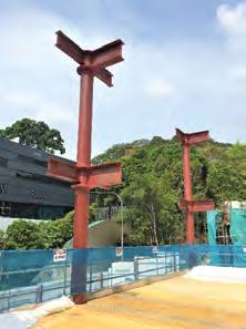
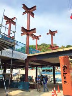
Prefabricated structural steel beam-column frames erected on site.
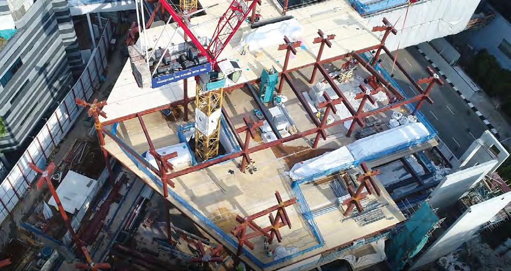
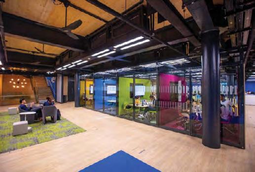
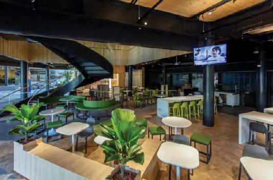
Large, flexible and aesthetically-pleasing spaces were created through innovative integration of structural and MEP systems.
The top of the CLT slab was protected with a waterproofing membrane. An acoustic membrane was laid over and finished off with 70 mm of floor screeding. The screeding serves to protect the two membranes and also conceal the floor trunking and service outlet boxes laid over the slab. CLT was adopted only for the sheltered and dry areas within the building. The slabs for wet areas, like toilets and MEP plant rooms, are made of composite steel decking. The cores and shear walls were constructed in conventional reinforced concrete. The 1st storey adopted a highly buildable flat plate system. The roof is a lightweight steel structure and roofing sheets, designed to support the weight of the PV solar panels and enable access for maintenance, have been used. The new building is supported on bored piles installed into the Fort Canning boulder bed.

Link Building design and construction
The Link Building connects the new educational block to the existing SMU School of Law, and had to be built over Fort Canning Link. The building comprises essentially two storeys and extends from the 3rd and 4th storeys of the main building, with a roof over it. It measures approximately 19 m x 27 m on plan and is supported on four columns. Its design and construction was one of the key challenges in the project. In order to bridge over the carriageway below and not affect its continued operation as a major artery that serves traffic coming from the east via Marina Coastal Expressway, East Coast Parkway and Nicol Highway, the Link Building is supported from the new building and by two new columns erected from the side table of SMU School of Law. There is also a requirement to maintain as high a headroom over the road as possible, so that motorists can see the Fort Canning Tunnel clearly as they approach it from Stamford Road. Erection of the Link Building was a critical consideration in the design. Early consultation and extensive brain-storming sessions were conducted internally and with the Land Transport Authority (LTA). Several options, with their pros and cons, were considered, and the number of options eventually narrowed down to two: • Option 1: Closing of Fort Canning Link for seven days to enable 24/7 construction. Motorists could temporarily use an alternative route to bypass Fort
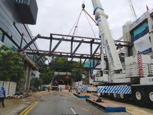
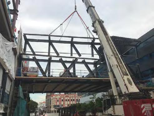
Canning Link. • Option 2: Construction of the Link Building only during non-peak hours, from 8 pm to 5.30 am, with partial road closure for 45 days. Fort Canning Link is a major arterial road (with a threelane carriageway) that provides direct connection from Stamford Road to Orchard Road. Option 1 would enable the Builder to erect the basic building structure and key services over the carriageway within seven days. Option 2 would entail the erection of the Link Building in smaller segments within a confined operational period. Temporary staging would be required to prop the erection and the whole construction would take up the planned duration of 45 days. LTA accepted Option 1. The challenge for the project team was then to work together with LTA to erect the building within this short time-period. Two ‘modified’ Pratt Trusses were designed to span 27 m across the carriageway to support the building. The trusses are integrated into the building design and are expressed architecturally within the interior spaces. The depth of these trusses spans over two floors, from the 3rd storey to the roof. This maximises the potential of the truss depth and enables optimisation of the element design. It has resulted in shallower chord and beam depths, thus achieving a high headroom over the carriageway, of about 7.5 m. The trusses are supported on two steel columns at the main building side. Two new columns supported on micropiles were constructed with a cross head to support the truss on the SMU School of Law side. The hybrid steel-CLT slab system has also been adopted for the Link Building, for ease of construction. Secondary beams spanning across the two trusses were designed to support the CLT panels. As the trusses are set back from the façade edge, the secondary beams were extended and cantilevered beyond the trusses with moment connections. The roof and landscape areas were designed in composite steel with concrete topping, instead of CLT panels. These areas are protected with a waterproofing membrane system since they are exposed directly to the weather. Each of the two trusses was divided into two segments, horizontally, for hoisting, using 500 ton and 350 ton cranes. The lower segments of the trusses were erected first. Nominal temporary ties and bracings were provided at the supports to stabilise the truss segments. The 3rd storey floor beams were progressively lifted and bolted to the trusses. The remaining two segments of the upper trusses were then erected over the lower segments. The joints of the trusses were welded on site. This was then followed by the installation of the 4th storey and roof beams.
During the whole process of installation, the truss segments were not propped nor supported temporarily from the road below. To facilitate the installation process and avoid unnecessary erection of falsework or temporary work over the carriageway, the lower segments of the trusses were engineered and designed to support the upper trusses and installation of the floor beams and CLT slab panels during erection. This enabled concurrent welding of the truss segments and erection of the other structural elements to expedite site work. The last activity, to complete the Link Building erection, was the concreting of the topping for the composite steel decking. This was carried out only after the two trusses were fully assembled and welded. The whole building structure was constructed within seven days, as planned, in spite of interruptions due to heavy downpours during this period. Fort Canning Link was reopened on time, as planned.
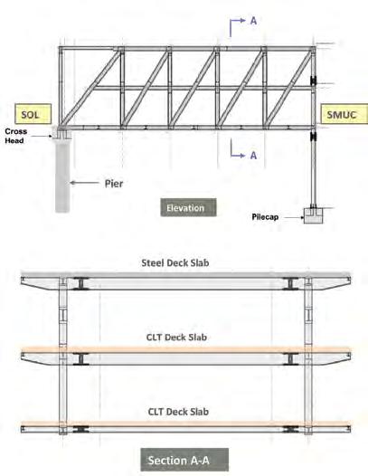
‘Modified’ Pratt Truss elevation and section. Installation of lower truss segments.


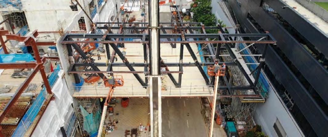
Welding of truss segments and installation of CLT panels.
SMU SOL
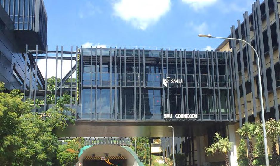
The Link Building.
Fort Canning Tunnel
Safeguarding existing services
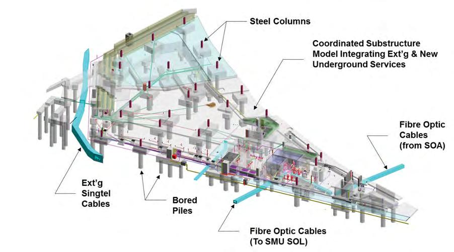
There are many services running below and adjacent to the site, which affected the design and construction. Some of these were either diverted, abandoned or safeguarded. The critical services that required safeguarding and integration with the new design or need to co-exist with the new design are: • The 10 m wide Stamford Canal sandwiched between
SMU School of Accountancy and the site. The canal was constructed as an open channel about 40 years ago and was subsequently slabbed over. • Critical Singtel cables and draw pit running across the site, which cannot be diverted. • Critical SMU data fibre optic cables and service sumps serving existing SMU schools. The Singtel cables serve critical facilities. Similarly, the fibre optic cables that serve existing SMU premises are also considered as critical infrastructure. Given the importance of the services and potential time delays, diversion and relocation of these services was not a consideration. There was also practically no space outside the site for the diversion or relocation of the services. The decision was taken, early, to integrate these critical services, thereby ensuring their co-existence within the overall building design. Structures were designed to bridge over and protect the services while, at the same time, enabling maintenance, repair or replacement, if required in the long term. The services were also safeguarded and monitored during pilecap and detention tank construction, to prevent damage. The SMU fibre optic cables were buried under Fort Canning Link and this affected the installation of the micropiles for the Link Building on the SMU School of Law side. The micropiles and columns were adjusted to avoid the cables, based on on-site measurements. As a result, a cantilevered cross-head was introduced to support the two trusses. There were also existing drains within the site, that served Fort Canning Park. These were relatively simpler to divert and manage, to make way for the new building and a new permanent drainage system that flows into the adjacent Stamford Canal.
As part of the project requirements to achieve the onsite net zero energy building status, solar panels were installed over the roof to collect and harness the energy. A solar verandah was also created to bridge the roof of the new building to the School of Accountancy across Stamford Canal. The solar verandah serves two purposes - to provide an additional platform to harvest solar energy as well as to offer an all-weather shelter for pedestrians at the 1st storey. It creates a large covered plaza extending between the new building and the School of Accountancy, which allows campus activities and programmes to be carried out within it. A link bridge was also constructed on the 3rd storey, to connect the new building to the School of Accountancy. Part of the new structures are supported from the School of Accountancy structures at the roof and Basement 1.
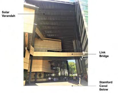
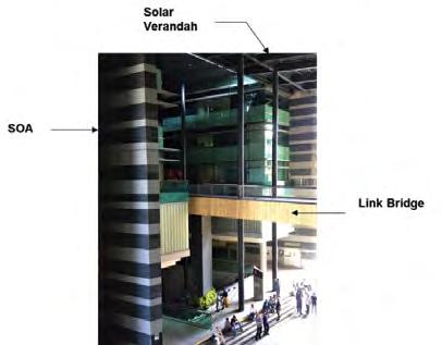
Solar verandah and link bridge to the School of Accountancy.
Both the verandah and link bridge were designed using structural steel, primarily to reduce the additional loads of the new build on the existing structures, as well as to facilitate construction. Steel members were essentially prefabricated off-site and delivered for on-site installation. The existing structures were analysed and checked in detail for the loadings from the new build. Several framing options were investigated, to minimise structural modification and overstressing of existing elements. The foundations and vertical structural elements were generally found to be adequate to support the new loads. Part of the 1st storey and basement beams were also checked and some were found to be inadequate to support the additional loads, despite the effort to redistribute them. These beams were strengthened using Carbon Fibre Reinforced Polymer (CFRP), before the new structures were erected.
Architectural staircases
There are two staircases in the building, that are designed as architectural icons. One is at the Central Plaza, from the 1st storey to the 3rd storey, and the other is within the Link Building, from the 3rd storey to the 4th storey, which serves the Business Incubator space. Both are spiral stairs. The stairs at the plaza was designed using structural steel. The curved stringers are framed using plates. The treads and risers were formed using thin folded plates. These folded plates serve two functions - to provide restraint to the stringer plates against lateral torsional buckling, and to also provide overall lateral stability to the stairs. Besides strength checks, vibration control was also a critical consideration in the design, as vibration can cause discomfort to people using the stairs. The stair components were mainly fabricated in the yard and delivered to site for erection. However, due to the need for full structural continuity of the stringers, welding was required on site to connect these members and the folded plates together. The stairs in the Link Building was constructed entirely in CLT. The design concept innovatively embraced the basic principles of physics and the theory of equilibrium. The design consists of a single column, with the steps radiating from it, from the 3rd storey to the 4th storey. The interesting feature is that the CLT stairs was fabricated entirely off site, with every piece having the same dimensions (except the final topping piece). These pieces are, in turn, stacked vertically to form the spiral. Each piece of the CLT panel came with the column and step fabricated together and cut to the exact size. Pre-formed holes in the CLT allowed steel rods to pass through to tie these pieces together as they were being stacked. The tie rods were then locked off and secured onto the floor slab and the top of the column. The selfweight of the stairs (column in compression) and the steel rods (within the column) provide the basic resistance to bending moments from the cantilevered steps. The staircase is lightweight and was erected expeditiously with minimal effort. It was a simple engineering idea which resulted in an iconic expression for all to appreciate. The other staircases were erected also predominantly in structural steel, with simple bolted connections on site. This avoided in-situ concreting and expedited the provision of vertical access to the floors for commencement of subsequent trades. The whole concept of DfMA was applied to the design and installation of the staircases, to enable off-site fabrication, better quality control and use of lighter and more sustainable materials and forms of construction, as well as to enhance productivity and buildability. This ultimately created a safer and cleaner work environment on site.
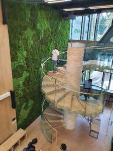
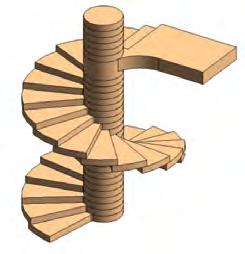
Spiral CLT stairs in the Link Building.
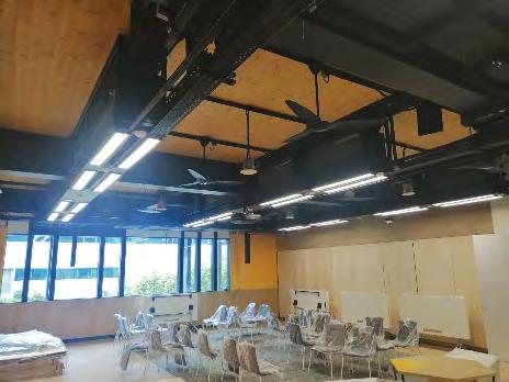
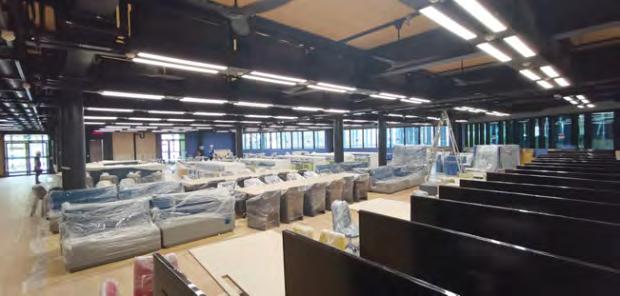
Modular M&E services.
Modular M&E systems
DfMA was adopted for C&S work and also extensively for M&E and architectural works. The main and secondary routing of M&E services were integrated into standardised and repetitive modules, to enable off-site fabrication. The routes and layout were coordinated early, through BIM, and mock ups were carried out on site to verify the design and feasibility. The modules are suspended from the soffit of the CLT slabs. As the services are integrated into modules, the loading consideration is different from that for a conventional design. The concentrated loads from the modules can be much higher than uniform loads that are typically assumed. The design of the CLT slab had taken into consideration these point loads as well as its char depth, in order to embed the fixings required for the suspension of the M&E modules. There is, generally, no ceiling provided for the learning spaces. The steel structure, CLT slab and the M&E services were carefully organised and expressed. Penetrations for services were created through the steel structures, to maximise the available floor height.
DfMA facade
The iconic building facade is a lightweight modular system which was also designed by adopting the principles of DfMA. The primary façade components comprising the window frames, sun shades, fire-rated boards and acetylated timber were fabricated and assembled offsite in modular panel sizes. These were then delivered, installed and finished off with waterproofing and fire sealant, on site. The secondary aluminum fins of the façade were installed on site, after the primary panels were in place. The modularisation of the façade further improved site productivity and buildability. Many of the façade panels are supported from the CLT slab, while the rest are either hung from the RC stairwalls or concrete slabs. The CLT slabs are generally cantilevered from the perimeter beams and were checked for these additional loads from the façade. The façade panels were connected to the CLT slab using aluminum floor brackets and wood screws. The stresses on the CLT slabs were also checked locally to ensure there would be no crushing due to the façade connections. The extensive connection of the external façade to CLT slabs in this project was a first-of-its-kind in Singapore. While the design demonstrated structural adequacy of the proposed detail, an actual scale model of a typical connection was made to verify its load-carrying capacity. Due to multiple load cases on the façade, the connection was subjected to different directional loads to ascertain its performance. The test results were satisfactory.
Collaboration among Project Team members
The design and coordination process was fully implemented by adopting the Virtual Design and Construction (VDC) management approach. Intensive coordination was carried out during design, by the team, and together with the Builder, after the award of the construction
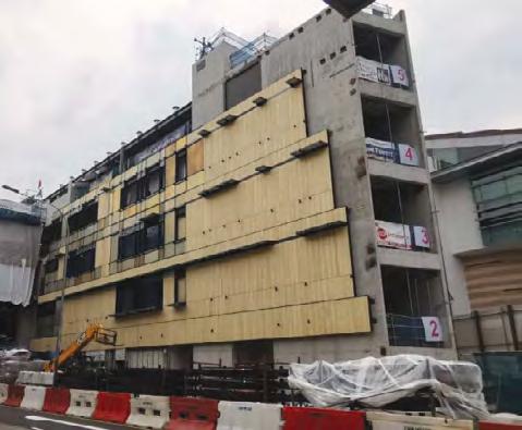
Installation of the DfMA façade.
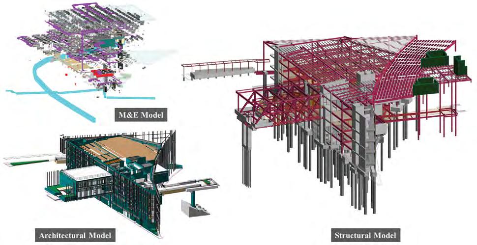
Architectural, structural and M&E models.
contract. The DfMA process demands the confirmation of design early, so that preparation and approval of shop drawings can be completed ahead of the procurement of structural steel and CLT panels. This process was required to be completed within three months after the main contract award. It is substantially different from conventional design where less intensive design coordination and approval is required so early. The design process was coordinated with Building Information Modelling (BIM). VDC sessions were conducted on a weekly basis to discuss and coordinate the design. Updating of the BIM models by the individual Consultants was carried out regularly. These models were uploaded and shared weekly for continued coordination and reviews. The BIM model prepared by the Consultants was issued with the main tender as a reference and as information for the bidders. After being awarded the contract, the Builder took over, to lead the main coordination of the works, jointly with the Consultants. It was an important process and a key part of the collaboration, to enable the on-time procurement, fabrication and erection of the steelwork, CLT slabs, modular M&E systems and DfMA façade, on site. This led to successful and timely completion of the project.
A QUALITY APPROACH
A collaborative approach was adopted for the design and construction, and accompanying specifications, involving the Client, Team of Consultants and Builder. Close design co-ordination and detailing ensured that there were no structural transfer elements in the new building, and safety considerations were incorporated into the design, from construction to maintenance. The design, detailing and specifications for the hybrid structural steel CLT slab system were documented to high standards, in line with the design requirements and quality expectations. As the system was relatively new in Singapore, extensive research and consultations with specialists, in particular on CLT, were carried out. The technical specifications for the CLT slabs were crafted to suit the project requirements and local conditions. Working closely with the Builder and with an open mind, the specifications and requirements were implemented on site to ensure the basic functions, testing regime, code compliance and performance standards, were met. The project was supervised on site with one Resident Engineer and two Resident Technical Officers. The incorporation of highly buildable features into the design, including modular M&E systems and the DfMA façade, improved constructability and overall site safety. The minimum Buildable Score required is 79 points. The Buildable Score achieved by the design is 87 points. The Concrete Usage Index (CUI) was approximately 0.26, which is much lower than the 0.35 m3/m2 required to achieve maximum points for the Green Mark Platinum Award. The Builder also adopted highly productive
construction technologies and systems. A Constructability Score of 73 points was achieved compared to the minimum requirement of 50.
CONSTRUCTION QUALITY & SAFETY
The unique structural system eliminated the need for any falsework or propping on site, to erect the floors. Construction and erection of the superstructure were made simple and safe. The critical site activity was the initial setting out and erection of the columns from the 1st storey. This had to be correct, to ensure smooth erection of the subsequent structural elements, due to the tight tolerance and precision required of the hybrid system. Once this was verified, the installation of the beams and CLT panels for the various floors was readily facilitated and undertaken expeditiously. Regular checks on the quality of the structural steel was carried out by periodic visits of the Qualified Site Supervisors (QSS) to the fabrication yard. An independent Testing Agency was also appointed to provide full time inspection and testing of the work, both in the yard and on site. The quality of the CLT panels was also a key consideration and requirement of the project, as these had to be expressed visually. The panels were cut and fabricated to the exact size in Austria. Close coordination among the project team members was needed upfront to finalise all shop drawings, setting out, dimensions, vertical penetrations, recesses, etc, in order to confirm the CLT order and production. Once the CLT panels are fabricated and transported, it would not be easy to modify them. Early design confirmation by all stakeholders was therefore essential. A visit to the fabrication yard in Ybbs, Austria, was carried out to witness the production and testing of one of the CLT batches. The objective of the visit was to understand and appreciate the CLT manufacturing process. The Quality Assurance and Quality Control in the production process and the associated verification tests for compliance and acceptance of the batch were also discussed and witnessed. In addition to ensuring that the production process was in order and in compliance with the requirements of the European Technical Assessment (ETA), two fullscale CLT slab tests were conducted in Singapore. In the tests, 140 mm thick and 220 mm thick panels were test-loaded to failure. These were verified and found to be consistent with the design output. The test results were satisfactory. Similarly, a fire test on a CLT sample was carried out in Italy and the results were verified by an accredited laboratory for performance compliance under the fire safety design codes. Connection of the CLT slabs, between adjacent panels, to the steel beams and other supporting elements like walls and brackets was effected through the use of wood screws. The wood screw was therefore a critical structural component for the overall integrity of the building structure. Load tests were also conducted on samples of the screws to ensure conformity.
INSPECTION AND TESTING PROGRAMME
Thorough and comprehensive risk analysis studies were carried out regularly for every stage of the construction process to identify the key risk issues and to control and mitigate the situation with preventive measures. A comprehensive instrumentation regime was put in place and monitored closely. Supervision of works was carried out progressively to ensure safety, quality and performance, in terms of meeting the progress targets set. Regular site meetings were held with the Builder to review and eliminate safety issues prior to the work activities. Inspection, testing and monitoring were carried out through quality checklists. Approved shop drawings were circulated to all relevant parties prior to construction, and inspection was carried out based only on approved drawings. The QP and the resident site team conducted regular site meetings and walks to ensure QA/QC.
DESIGN FOR SAFE INSPECTION AND MAINTENANCE
The safe inspection and maintenance of the building after completion was a key consideration at the outset of the project. Reference was made to BCA’s Design for Maintainability checklist. As the structural elements are generally exposed and expressed architecturally, the inspection of the structural elements can be carried out easily, at any time, and especially during the mandatory inspection every five years. Similarly, since most of the M&E services and fixtures at every floor are well organised (arranged in standardised and repetitive modules) and exposed without a ceiling, the inspection, maintenance and replacement of any fixture can be carried out readily. The major MEP equipment are also generally located near the lift. Therefore, replacement of a whole equipment or parts of it can be carried out in future, without difficulty, whenever required. The inspection and maintenance of the building façade can be carried out by several means. For lowrise areas, lifts, scissor lifts and/or cherry pickers can be used. For the maintenance of high volume spaces and along the building edges, a building maintenance unit that can move along a monorail was installed to facilitate cleaning, inspection and servicing. The solar panels installed over the main roof and the verandah can, likewise, be readily maintained and serviced over the building life. Access to all these areas has been detailed and provided, with safety railings and life lines. The roof structure was designed, taking into consideration also the loads from the placement of the solar panels and access for maintenance. Besides the general requirements for maintenance of any building, there is also a need to establish a maintenance regime and guidelines for the CLT slabs. The Builder and the CLT specialist supplier formulated an Operation and Maintenance Manual for the Owner,
upon completion. The manual basically outlines the common causes of damage to CLT, maintenance guidelines, management of CLT slabs and visual inspection. Reference was also made to BCA’s Design for Manufacturing and Assembly (DfMA) of Mass Engineered Timber Guide Book.
CONCLUSION
SMU Connexion was successfully completed safely and on time, with no public safety incident or adverse feedback throughout the construction. By adopting holistic DfMA technologies, manpower savings of approximately 26% was achieved. The corresponding productivity improvement was 35%. The project achieved the initial design objective to be a sustainable and green building, meeting both BCA’s Green Mark Platinum and the international WELL Building Standards. The project has also achieved a high-quality standard expected of a new building for a top university.
All images by SMU
PROJECT CREDITS
Project
SMU Connexion (A-South 2)
Location
40 Stamford Road, Singapore 178908
Developer
Singapore Management University (SMU)
Architect
MKPL Architects Pte Ltd
Civil & Structural Engineer
Meinhardt (Singapore) Pte Ltd
Mechanical & Electrical Engineer
Meinhardt (Singapore) Pte Ltd
Quantity Surveyor
Rider Levett Bucknall LLP
Builder
Singapore Engineering & Construction Pte Ltd