4 minute read
From failure analysis to gearbox design A logical approach can lead to the selection of the right option


FROM FAILURE ANALYSIS TO GEARBOX RE-DESIGN
by Robert Shandro, Principal Consultant, Cetim-Matcor
A logical failure analysis approach is more than just a diagnosis. It is an appropriate method of observation and analysis, based on specific knowledge and extensive experience, that leverages a global vision of the failure to provide advice for improvement and redesign.
Robert Shandro
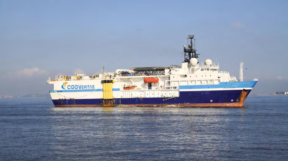
Oceanic Phoenix. Image: Wikimedia Commons/Halley Pacheco de Oliveira.
Oceanic Phoenix, owned by CGGVeritas, is an offshore scientific research vessel used for the acquisition of seismic data from the seabed. The vessel faced a significant problem a few years ago. The tapered roller bearings of the gearboxes in the power transmission system were subjected to an alarming level of vibrations - 20 mm/s RMS instead of the recommended 7 mm/s. These vibrations caused the failure of the bearings. The propulsion system is composed of two shaft lines and a variable pitch propeller. Each shaft is driven by two 2 MW electric motors via a gearbox that reduces the rotation speed of the motors from 900 RPM to 130 RPM. This redundancy in the architecture was expected to allow the vessel to operate in a degraded mode, in the event of a failure of one of the two systems. Despite this, defects occurred in both gearboxes.
No shutdown during onsite operation
Two on-board missions conducted during technical downtime of the vessel helped to identify the cause of the failure. The teeth extremities of the input pinions were damaged (in the tooth root region) by micropitting and pitting. The maximum density of the surface degradation corresponded to the area with maximum intensity of the surface contact pressure (the localised tooth contact pattern). Also, one tooth of the input
Broken tooth of input pinion. The cracking was initiated under the case hardened layer and it then propagated parallel with the tooth flank.

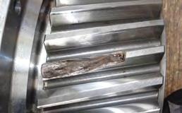
Spalling on the running path pattern of the outer ring of the tapered roller bearing.

pinion was found to be broken at the extremity. A large part of the tooth was detached due to crack propagation along the case/core transition area. Also, the middle shaft’s tapered roller bearings were more damaged than the other bearings. Significant spalling was observed on the outer rings of the bearing, specifically localised at the loaded area. The input shaft bearings had a running path pattern, varying in width on
two diametrically opposed areas. These point to an outer ring misaligned in the housing or a shaft misalignment.
Detailed modelling of gearbox
Examinations performed on-board allowed Cetim-Matcor to conclude that observed damage on gear wheels and on bearings were due to: • Gearbox rigidity • Shaft deflection and misalignment • Bearing selection and mounting • Microgeometry of gears (tooth flank modifications) Based on the results of on-site examinations, it was decided to create a detailed model of the housing, shafts and bearings (by using their detailed internal geometry) as well as gears (focusing on the gear microgeometry). The main objective of the global calculation was to acquire a further understanding of the operating conditions. The calculations (according to the standards ISO 6336, ISO/TS 16281 and DIN 743), confirmed the assumptions drawn from the examinations and measurements. In fact, the housing deformation and inaccurate tooth flank modifications were responsible for excessive vibrations, failure of the bearings and premature teeth rupture. With regard to the teeth, it was found that these deformations caused misalignment which led to an excessive load applied to the extremity of the teeth, resulting in their premature damage.
The solution
Two solutions are generally possible - reconstructing the shaft line or solidifying the housing. The first solution is extremely expensive and the second would put the vessel out of operation for an excessively long time. The alternative from Cetim-Matcor, which was implemented, involved adapting the teeth microgeometry to the housing deformation. The aim was to find a solution that would ensure the loads on the pinions are distributed at the right place, in the centre of the teeth, even if the deformations are present. As a result, the excessive vibrations had fully disappeared. The bearings are no longer affected and the teeth are no longer subjected to degradation.
Conclusion
This case study describes how a logical failure analysis approach can help in understanding the failure of power transmission components, by indicating the probable causes as well as proposing the right corrective actions and palliative measures. Moreover, the implementation of an appropriate method, using powerful and extensive software, makes it possible to confirm the cause of the failure. This is achieved by combining the global approach and detailed component analysis, in order to get a further understanding of gear mesh behaviour during operating conditions.

Modelling of gearbox.

Stress distribution on pinion tooth flank (before and after modifications).
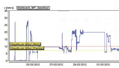

Level of vibrations, measured before and after optimisation of tooth flank modifications.
(This article is based on a presentation made by Mr Robert Shandro at the webinar titled ‘Power Transmission - From Failure to Re-Design’, organised by the Institution of Engineers, Singapore (IES) and held on 29 July 2020).
All images by Cetim-Matcor, unless otherwise stated.


