18 minute read
The world’s first 15-cell caterpillar-shaped cofferdam design for Tuen Mun - Chek Lap Kok Link in Hong Kong The article presents the technical challenges in the design and construction
THE WORLD’S FIRST 15-CELL CATERPILLARSHAPED COFFERDAM DESIGN FOR TUEN MUN - CHEK LAP KOK LINK IN HONG KONG
The article presents the technical considerations and challenges in both design and construction associated with the innovative caterpillar scheme and its benefits as compared with the conventional approach using straight diaphragm walls.
INTRODUCTION
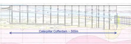
Tuen Mun - Chek Lap Kok Link (TM-CLKL) is a 5 km subsea road link which will provide the most direct route between Hong Kong’s Northwest Territories and Hong Kong Island. It forms part of the Hong Kong - Zhuhai - Macau Bridge project which was officially opened in late 2018. The world’s longest sea crossing reduces freight and passenger travel time between the three cities to within an hour and plays an important role in promoting the integration of the Greater Bay area. With an innovative new design and construction approach, the project team successfully overcame the challenges of adverse geology and a tight programme, whilst reducing construction risks and costs. The uniqueness and challenge of the project was influenced by its large scale. Being constructed in newly reclaimed land added another layer of complexity to the engineering challenge. The key scope of this project was to construct the 630 m long and maximum 33 m wide South Cut-and-Cover Tunnel (SCC) and the Southern Landfall Approach Ramp (SAR) at the southern landfall of the TM-CLKL Northern Connection Sub-sea Tunnel Section site which is a newly reclaimed land with more than 20 m thick marine deposit/alluvium. The maximum excavation depth is around 43 m. Instead of the conventional excavation and lateral support scheme with straight diaphragm walls and steel struts, an innovative idea was developed. The idea was to utilise a 500 m long caterpillar-shaped cofferdam with 15 cells, each of which is formed by perimeter diaphragm wall panels installed in an arc shape and laterally supported by reinforced concrete struts at the locations of specially designed ‘Y-panels’ - which presents another world first in terms of slurry trench size and complicated reinforcement. The caterpillar is a sustainable and environmentfriendly solution, achieved through substantially reducing the use of steel struts and ground treatment. The success of the project also relied heavily on the combined use of the computer programmes PLAXIS and SAP2000, which enabled the soil structure interaction analysis of the highly complicated ground structure.
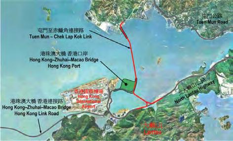
Figure 1: Tuen Mun - Chek Lap Kok Link project plan.
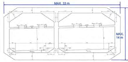
Figure 2: South Cut-and-Cover Tunnel box structure.
The project demonstrates a high level of innovation, engineering excellence and close collaboration between designers and contractors, which have proven to be key to the success of the overall project, adding tremendous social and economic value to Hong Kong and the Greater Bay Area through improved connectivity.
PROJECT BACKGROUND
In August 2013, Dragages-Bouygues Joint Venture (DBJV) was awarded the design and build contract for the TM-CLKL Northern Connection Sub-sea Tunnel Section (Figure 1). The major works under this contract, which is valued at approximately HKD 18.2 billion, included: • Reclamation of approximately 16.5 hectares at Tuen
Mun Area 40 as the Northern Landfall of the sub-sea tunnel.
Atkins wins award for innovation
Atkins, a member of the SNC-Lavalin Group, has won the 2020 HKIE (Hong Kong Institution of Engineers) Innovation Award for a world-first cofferdam design approach on the Tuen Mun - Chek Lap Kok Link (TM-CLKL) project in Hong Kong. Due to the complex ground conditions, Atkins, who is supporting Dragages-Bouygues JV on the project, designed the world’s longest and largest caterpillarshaped cofferdam in which TM-CLKL’s cut-andcover tunnel is constructed. At 500 m in length and 43 m in depth, the 15-cell cofferdam design approach could save HKD 500 million to 1 billion and six to 10 months in construction time. The innovative cofferdam design on TM-CLKL project was also recognised at the 2019 NCE Tunnelling Awards in London. Atkins, alongside Dragages-Bouygues JV, won the Innovation in Design and Delivery Award for the caterpillar-shaped cofferdam for TM-CLKL’s cut-and-cover tunnel, and Atkins was also recognised at the 2019 International Tunnel Awards which named TM-CLKL Major Project of the Year with a budget of more than EUR 500 million.
Atkins
Atkins is a design, engineering and project management consultancy, employing over 18,300 people across the UK, North America, Middle East and Africa, Asia Pacific and Europe.
SNC-Lavalin
Founded in 1911, SNC-Lavalin is a fully integrated professional services and project management company with offices around the world.
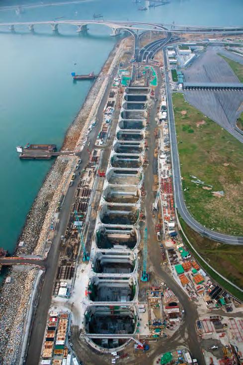
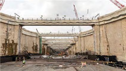
The 15-cell caterpillar-shaped cofferdam.
• Dual two-lane sub-sea tunnel (two tubes) approximately 5 km long between the Northern
Landfall and Southern Landfall, excavated using three slurry-shield Tunnel Boring Machines (TBMs), one of which is the world’s largest, with 17.63 m excavation diameter and the other two are identical, with an excavation diameter of 14.00 m. • Ventilation shafts and buildings, cut-and-cover tunnels and approach ramps at both Northern Landfall and
Southern Landfall. Atkins, a member of the SNC-Lavalin Group, was appointed by DBJV to carry out the design for the Permanent Works (including tunnel structures and its space-proofing, roadworks and drainage) and Temporary Works (mainly the excavation and lateral support) for the Southern Landfall Approach Ramp (SAR) and South Cut-&-Cover Tunnel (SCC), with a total length of about 630 m. The permanent two-cell tunnel box (as shown in Figure 2) is maximum 33 m wide and generally 14 m high, and required maximum 43 m deep excavation within the newly reclaimed land.
STRONG DEMAND FOR AN INNOVATIVE SCHEME
Difficulty with the site geology
The SCC Tunnel is located at the newly reclaimed area at the HZMB Hong Kong Port (HKP). The geological sequence comprises reclamation fill (approximately 15 m thick), marine deposit (approximately 10 m to 15 m thick), then alluvium (approximately 20 m to 30 m thick), and then highly decomposed granite, meta-siltstone or meta-sandstone (with varying thickness) before reaching engineering rockhead. The excavation is maximum 43 m deep and based on the geotechnical interpretation, it would encounter soft clay layers (marine clay and alluvial clay) of around 30 m thick. Figure 3 shows the geological profile along the SCC Tunnel.
The site geology which is particularly variable as regards the continuity of alluvial sand layers, together with the potential impact on nearby sensitive receivers, imposed more difficulties and risks for the conventional scheme, with straight diaphragm wall (D-wall) and steel struts, to work within the project time-frame and budget.
The caterpillar scheme versus the conventional scheme
An initial scheme utilising the conventional straight D-wall was studied (Figure 4). Up to nine layers of closely-spaced (approximately 4 m vertically and minimum 6 m horizontally) strutting with large steel members are required. Moreover, it would need extensive ground strengthening works below/near the excavation level to strut the D-wall, since the untreated soft ground layers cannot provide sufficient lateral stiffness for the D-wall. In addition, two TBMs of 14 m diameter had to break through at the northern end of the cofferdam. The space would be extremely tight for the cofferdam, with such close strut spacings. Also, the risk level in adopting the conventional scheme for deep excavation in soft clay could not be overlooked. Taking into account some past failures, the Designer seriously considered the risk, particularly the uncertainty in the strut design. For instance, the strut/ waler connection is designed as ‘pinned’ but is rigidly connected on site. The rigidity could induce additional bending on the strut when the wall bends. The idea of the 15-cell caterpillar cofferdam (Figure 5), which counts on the D-wall panels in an arc shape and eliminates the closely spaced steel struts, was developed and implemented. Instead of the steel struts, reinforced concrete struts with average vertical spacing of 8 m and a minimum horizontal spacing of 25.5 m were used. More details are given elsewhere in the article. The advantages of the caterpillar cofferdam scheme over the conventional scheme, in terms of safety and economics, are as follows: • From the environmental point of view, the innovative caterpillar cofferdam has eliminated over 21,000 t of steel and 80,000 m3 of ground treatment. This reduces the carbon footprint generated from the material production and transportation, and enhances the sustainability. • Site safety was greatly enhanced with no propping works at height and no heavy strut liftings for installation and removal. The risk of site congestion due to strutting was eliminated and excavation plants were able to work in an unrestricted manner. • The elimination of congested steel struts allows fasttracking of all related activities, including excavation, retrieval of TBMs and construction of the tunnel box structures. The RC struts for the caterpillar are arranged to provide a clear headroom of 16.5 m above the formation level, which allows using travelling formworks for the permanent structures. Re-propping / box-out, during the construction of the permanent tunnel structures, necessary if using steel struts, was not required. This reduces the number of construction joints (CJ) and subsequently the risk of potential water seepage/leakage through the CJ. Ultimately the maintenance cost could be reduced and sustainability is enhanced considering the whole life cycle. • In terms of the construction programme, savings of 6 to 10 months was forecast, compared to the conventional scheme.

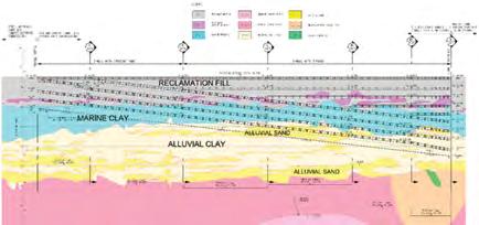
Figure 4: Conventional Excavation and Lateral Support (ELS) Scheme (plan and longitudinal section) with straight D-wall and steel struts.

• Due to the geometric nature of the perimeter arc
D-walls for the caterpillar scheme, destabilising pressure at the D-wall toe, from the retained side, is resisted by the hoop action among the arc D-walls and eventually transferred to the Y-panels and cross walls.
Hence, the toe stability against kick-out failure was not a concern. The caterpillar D-wall embedding depth and toe grouting could then be substantially reduced as compared with the conventional scheme.
GENERAL ARRANGEMENT OF THE CATERPILLAR
The typical arrangement of the caterpillar cofferdam and the load transfer are shown in Figure 6. The caterpillar consists of 15 cells, each of which is formed by perimeter D-wall (1.2 m or 1.5 m thick) panels arranged in an arc shape, which will resist lateral pressures mainly by means of hoop force. The longitudinal span of the cells varies from 25 m to 36.5 m and the radius of curvature of the arc D-wall varies from 22 m to 28.5 m. At the interface between cells, the hoop forces induced on the perimeter arc D-walls will be transferred to the ‘Y-panels’ (Figure 7 shows the geometry) which are hammer-shaped with overall 6.5 m length and maximum 3.6 m width, constructed by 5-bite D-wall trench excavation. More details are given elsewhere in the article. The Y-panels are laterally supported by the reinforced concrete struts vertically spaced at around 8 m to 11 m centre-to-centre, with maximum three layers at the deepest excavation and a single layer at the shallower section. The RC struts are typically 2 m wide x 2 m deep, but some of the lowest struts are 3.2 m wide x 2.8 m deep. The bottom corners of the lowest struts are chamfered to reduce the Y-panel bending moment. At the strut connection with the Y-panel, the ‘wing corbel’ (Figure 8) was proposed for strengthening. Cross walls, in the form of continuous D-wall panels (1.2 m or 1.5 m thick), laterally support the Y-panels below the final excavation level. Above the cutoff levels of the cross wall panels, the excavated
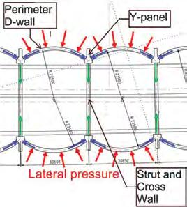
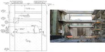
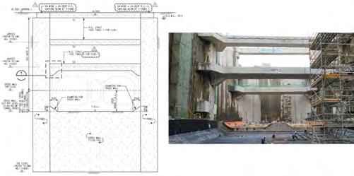
trenches were backfilled with lean concrete to provide pre-support to the Y-panels before the RC strut installation, so that the bending moment of the Y-panels could be reduced. A capping beam, generally 2 m wide x 2 m deep and widened at the location of the Y-panel, is provided on top of the perimeter arc D-walls and Y-panels to enhance the cofferdam integrity. Figure 9 shows the typical ELS section at the Y-panel location.
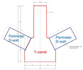
Figure 7: Y-panel geometry.
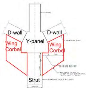
Figuer 8: Wing corbel for strut.
TECHNICAL CONSIDERATIONS AND CHALLENGES
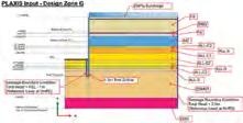
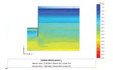
Axisymmetric analyses, using the computer programme PLAXIS 2D (Figure 10), which take into account the soil-structure interaction, were performed to evaluate the lateral earth pressures, water pressures and ground spring stiffness, which were then input to the structural analysis models. Seepage analyses and staged excavation were considered in the PLAXIS axisymmetric analyses to calculate the lateral earth pressures and pore water distribution inside and outside the excavation, resulting from pumped dewatering below the excavation. The ‘PLAXIS’ analyses were conducted for each caterpillar cell with a different excavation depth and design geological profile. Three-dimensional structural analyses of the caterpillar cofferdam were then performed using the computer programme SAP 2000. The SAP2000 analyses account for the three-dimensional geometry of the caterpillar cells, including the D-wall openings at the TBM breakthrough and the strengthening tympanum. The perimeter arc D-wall, cross walls, struts and Y-panels are represented by a series of thin-shell elements. The ground medium surrounding the perimeter D-wall is represented by a series of area springs perpendicular to the shells. In case of tension, the ground springs are ignored and no reaction is given to the D-wall. Considering the total length of around 500 m for the 15-cell caterpillar cofferdam, its structural analyses were split into three models, each of which was assigned with the appropriate boundary restraints. PLAXIS 3D analysis, which takes into account the soil-structure interaction, was also used to study the overall behaviour of the caterpillar, in terms of movement and induced forces, and compared with SAP2000 models. After having presented the general design and analytical approach, the following sub-sections highlight some specific considerations and challenges in terms of both design and construction of the caterpillar.
Longitudinal stability
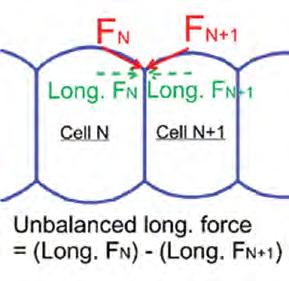
An arch structure primarily counts on the lateral restraint at its support. Hence, at the early design development stage, it was realised that the longitudinal stability would be crucial for the caterpillar cofferdam which, in principle, counts on the arching effect to resist the lateral loads. To achieve this objective, the arc radius and longitudinal span of each cell had to be calculated in relation to its adjacent cells. From the Contractor’s point of view, it would have been preferable to have a larger radius and span (in principle, the shallower the excavation, the larger the cell radius and span could be) so that there would be less excavation volume and also less cross wall/Y-panels. However, the Designer had to optimise these geometric parameters in parallel with the consideration of the structural capacities of the Y-panels and cross walls, as well as minimise the unbalanced load in the longitudinal direction between adjacent cells (Figure 11).
D-wall panel joint in structural modelling and design
The caterpillar cofferdam primarily consists of D-wall panels and hence it is not possible to have rebar continuity across the panel joints. When subjected to the combined effects of hoop (i.e. horizontal) axial force and bending moment, these joints can only act in compression but not in tension. ‘Tension cut-off’ (i.e. no tensile stress) was assigned to the D-wall elements in the SAP2000 structural analysis to mimic this behaviour. The perimeter D-wall structural capacity subjected to the hoop forces was checked using the moment-axial force (M-N) interaction diagram, assuming plain concrete, to account for the rebar discontinuity at the panel joints. In the M-N interaction diagram, the governing parameters for the structural capacity are D-wall concrete grade and thickness. For the latter, reduced contact thickness at the D-wall panel joints that resulted from the verticality tolerance was duly considered. In view of the above design considerations, the verticality control on site is more stringent as
compared with the conventional straight D-wall. Generally a maximum 1:200 verticality is specified, whilst for some other panels with less design margin, a maximum 100 mm relative dislocation between adjacent panels is required. And for Y-panels, which are the key structural elements of the caterpillar scheme, the maximum verticality is 1:400.
Y-panels
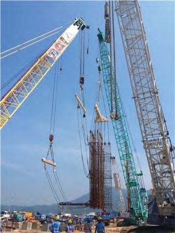
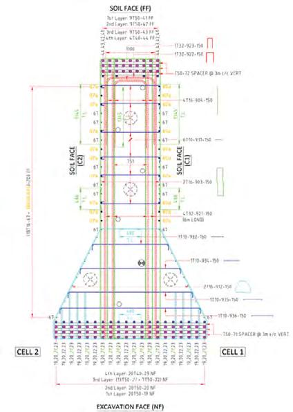
The Y-panels are key structural elements in the caterpillar scheme as all the perimeter D-walls transfer the loadings to them. For ease of permanent tunnel structure construction, the levels of the lowest struts were arranged to provide the required clear headroom (around 16.5 m) without any obstacles. The Y-panel cross-section had to be sufficiently large to limit the ultimate shear stress (corresponding to a maximum factored shear force of around 73,000 kN), in accordance with the design standard. The wide front end (3.6 m) provided much more space for the main bars on the excavation face and allowed the stacking of sufficient rebar to take the extreme bending moments (maximum factored is 310,000 kNm). Other than the concern on the structural capacity, the Y-panel geometry had to suit different cell radii and spans, as well as the trench excavation methodology. Subject to the point of action from the perimeter D-walls (similar to a bottom-loaded beam), tension tie bars were required which made the Y-panels more congested, with rebars already required for bending and shear (Figure 12 shows the heavily reinforced Y-panel cross section). The extremely heavy rebar cage (maximum 135 t) made the steel fixing as well as lifting operation on site difficult. A combination of prefabricated rebar cages and in-situ fixed cages were used for one single Y-panel. Large cranes up to 400 t capacity and up to triple lifts were utilised for cage lifting (Figure 13). In terms of rebar detailing, the reinforcement arrangement had to allow for other D-wall installation provisions like grout tubes, sonic tubes and D-wall stop-end, and hence there was high demand for rebar optimisation. In order to excavate a trench 6.5 m long, 3.6 m wide at its base, and 55.5 m deep for the deepest Y-panel, a 5-bite excavation solution was required (Figure 14). There was no previous experience for such a trench (15.6 m2 cross sectional area and 860 m3 volume). Cement-soil mixing (CSM) was adopted around the excavation perimeter as ground strengthening works, in addition to bentonite slurry within the trench excavation.
Three-dimensional PLAXIS analysis (Figure 15) was performed to evaluate the trench stability. Trials with the panels were conducted on site, together with instrumentation (ground settlement markers and inclinometers) and monitoring, to verify the trench stability for Y-panel excavation with CSM before fully implementing the ground strengthening works.
SUMMARY AND CONCLUSION
The successful design and construction of the largescale 15-cell caterpillar-shaped cofferdam on newly reclaimed land is a significant milestone for Hong Kong’s construction industry and tunnelling, worldwide. During construction, a stringent instrumentation and monitoring plan was implemented on site, which included the installation of ground settlement markers, D-wall movement markers and inclinometers, piezometers, strain gauges in struts etc. Inclinometers were installed on every Y-panel which was considered as a critical structural element in the caterpillar scheme. Design reviews were conducted at intermediate excavation stages, based on monitoring records. The caterpillar cofferdam was successfully backfilled without obstruction, in May 2020. With the objectives of completing the strategic project safely, on time, on budget and with the least environmental impact, the challenging and unique project benefitted greatly from the innovative design approach, state-of-the-art design software and close collaboration between stakeholders.
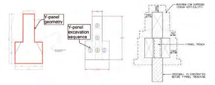
Figure 14: 5-bite trench excavation for Y-panel.
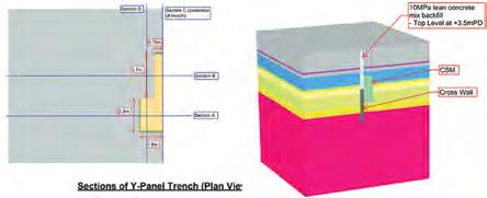
Figure 15: 3D PLAXIS analysis for Y-panel trench stability.
All images by Atkins
Infrastructure leaders predict recovery within 18 months
Atkins recently shared the findings of its independent research which assesses the impact of COVID-19 on the UK infrastructure sector, measures confidence, and explores the roles of government and the private sector during recovery. The work, which was carried out by the independent market research organisation, Savanta ComRes, on behalf of Atkins, involved a comprehensive survey of senior public and private sector decision- makers across different subsectors within infrastructure, particularly transport, property and utilities. In total, 398 responses were obtained via an online survey during June and July 2020 and eight in-depth interviews were conducted. The report, entitled ‘Infrastructure Insights: COVID Impact and Recovery’, found that while the industry has been impacted by the pandemic, with organisations reporting that 16% of the work they had immediately before COVID-19 had been postponed or cancelled completely, 52% of senior decision-makers were confident that they would see outlooks for the sector return to pre-crisis levels by Q4 of 2021. In the private sector, almost seven in 10 respondents predicted a return to their organisation’s pre-crisis outlook before the end of next year. The report also reveals that 65% of senior decision-makers would like to see the government provide a clear roadmap to help the sector with the recovery from COVID-19, while 53% want to see increased spending beyond the 2020 budget commitments, and 53% called for better co-ordination between the central and local governments. There is general agreement that the sector will not emerge from the crisis in the same form, with the vast majority of respondents agreeing that digital innovation will be increasingly important. It is also clear that senior decision-makers want to see digital innovations from the design, engineering and consultancy sector help support their organisations during the COVID-19 crisis and recovery. Richard Robinson, Atkins UK&E CEO said, “The findings set out in this report represent a compelling and powerful take on the sector and its path forward. “While it is clear that we need a finalised National Infrastructure Strategy to give us more clarity and confidence, there is an expectation for the private sector to step up the use of technology and data to accelerate the recovery, by building back smarter as well as better”, he added. Atkins’ ‘Infrastructure Insights: COVID Impact and Recovery’ may be downloaded from the company’s website.


