17 minute read
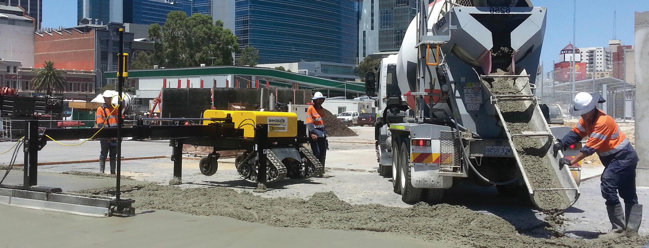
Personality trends . . . . . . . . . . . . . . . . . . . . . . . . . . . . . . . . . . . 26 Mario Florio, director of the global All States Concrete Equipment


cept is easy for a businessperson to understand – he’s outlaying quarter of a million but saving half a million.
“We work in Indonesia where there is very high unemployment and creating jobs is their no.1 priority, and they still recognise the economics of mechanising in instances where there are large projects with a timeline. If you have a machine that can speed up that timeline, you can then allocate your spare men to different areas, whether it’s boxing up a slab, or putting reinforcement on the ground,” he explains.
Advertisement
It’s about efficiency and quality. Worldwide, people want quality at an affordable price.
RESEARCH, DISCOVERY AND TRAINING
“At All States, we’re constantly thinking about the outside of the box, and that is my personal responsibility within the company because I’ve been a contractor. I have silica fumes running through my veins and have been in concrete all my life, so I know what a contractor wants. For instance, with our concrete trowel machines – we look at how we can be better than anyone else. We came up with the idea of a vertical trowel machine, also called power trails, helicopters and choppers – various names around the world.” Every country is different. Florio explains that many countries in Asia don’t use cranes for lifting machines like the big ride-on power trowels. They are very heavy, starting from 230kg to 800kg – and the majority of Asian companies don’t have cranes to lift them up. “We had to innovate to see how we could help these companies efficiently and cost effective, because having a truck with a crane is very expensive.
“Let’s say someone wants to be a bit more adventurous in business and wants to do something different - like a super flat floor. They may need to put a dry shake hardener on top of the floor. Some people throw it on by hand like they’re feeding chickens. We have machines where we put all the hardener in a tub which can be walked along rolling evenly. There are also boom operated machines with the boom protruding up to six meters dry shaking the hardener evenly,” says Florio.
Training is specific to each machine and is central to safety. “First of all, safety is critical and customers need to be made aware of the hazards of any machine, from a hand tool’s sharp blade through to the laser screed, where getting crushed or run over is the threat.
GLOBAL TRENDS
“I travel the world doing this now. The company has local partners in various countries such as Indonesia and South Africa. For us, it’s not just about selling a machine, we sell a solution – and that requires an ongoing relationship to constantly determine their needs. Florio explains that he’s been contracting since he was 19 and in flat floors for 25 years. “When I acquired my first laser screed about 25 years ago, I only had six employees. And that laser screed cost me A$600,000 back then. That grew my business rapidly to having four laser screeds and 40 employees, including subcontractors. I was able to grow the business through the quality of my work and understanding that when you have a machine like the Ligchine people start looking at you differently, as if to say they know the quality of work that it can do. I grew a small business to a large one, and that’s what we help other small businesses do. A developer or builder knows it can get a cheaper price from them compared to the high-end guys - and that’s how small businesses grow. We target the smaller businesses to help them achieve what they want to achieve and grow.”
Each country is a completely different market. Some contractors have all the equipment, but the most important are the laser screed and trowel machine. “There are contractors that still screed concrete by hand or still use power trowels or walk behind power trowels and have a measuring tool for flatness. In contrast, with a laser screed it is a package that does everything at once.
“There are contractors that want equipment that can do everything, and others that also want to do everything but can’t afford it. But they will at least want the equipment to measure the floor.”
He notes that even a laser screed cannot be 100% perfect. “You still have to be vigilant for ‘what ifs. What if one of the laser rides breaks down? You need spare parts, and what is the site carrying on the day. You can never just use a machine and not worry about maintenance or spare parts.” n
Lourensford Motor Museum
landscaped with exposed aggregate paving
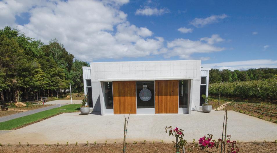
The landscaped area surrounding the recently-built motor museum at Lourensford Wine Estate in Somerset West, was completed in October. It comprises an orderly combination of exposed aggregate paving, cobble paving, gravel-covered paths, grass, potted plants and flower beds.
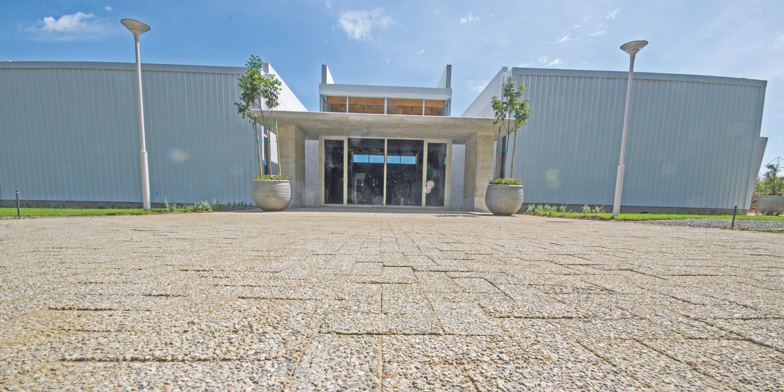
The paved area outside the museum’s main entrance.
The north-facing vehicle entrance. The paved driveway and vehicle entrance at the southern end of the museum.
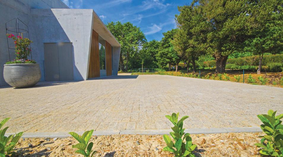
Concrete Manufacturers Association member, C.E.L. Paving Products, supplied 500m² of its Brownstone course exposed aggregate paver which was used to pave the vehicle entrance areas at either end of the building and a section flanking the museum’s main entrance. C.E.L. also supplied its bond paver which was used as the paving’s header course.
Museum architect, Anton Heyn, said he specified C.E.L.’s Brownstone paver as one of the main landscaping elements because it is an attractive and durable non-slip product which complements the site’s other landscaping elements.
“The paver is embedded with natural stone which adds a natural look and feel to the museum’s landscaping ‘language’. We could have specified an in-situ paving installation but given that the site was built with several services which require maintenance or add-ons from time-to-time, paving blocks proved to be the more practical solution; they can easily be lifted and replaced without damaging or marring the paved surface.”
The paving work was executed by the project’s main contractor, Buildaway. The layer works comprised a compacted sub-grade, 150mm of G5 aggregate and 20mm of bedding sand. n
Precast concrete panelling
enhances Stellenbosch University building
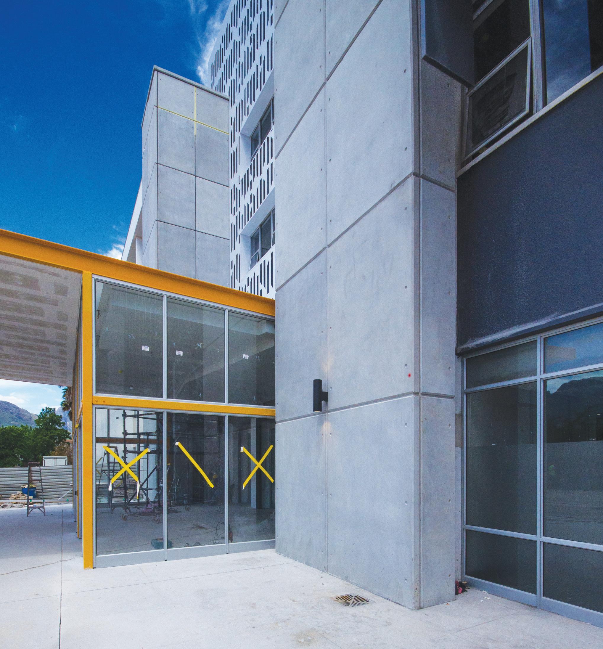
Reinforced precast concrete facade panels, manufactured by Concrete Manufacturers Association member, Concrete Units, have been used to dress the external elevations of two U-shaped service shafts which flank the northern entrance of Stellenbosch University’s Civil, Electrical and Electronic Engineering building.
The installation forms part of an overall face-lifting and refurbishment of the five-storey structure which is being undertaken on behalf of the university by main contractor, GVK-Siya Zama Construction, in collaboration with project architect, KMH Architects, and structural engineers, Edifice Consulting Engineers Forty panels in six sizes were attached to each shaft’s three exterior elevations over eight segments, five panels dressing each segment. All the panels are 2.2m high, apart from the top or eighth segment units which are 1.4m, and they all vary in width from 400mm to 1 700mm. The front or north facing elevations of each shaft took 16 panels as did the two inner side-facing facades. The two outer side-facing elevations were each dressed with eight narrower panels.
Rynhard Zwarts of KMH Architects said he specified precast concrete panelling for the service shaft facades to create
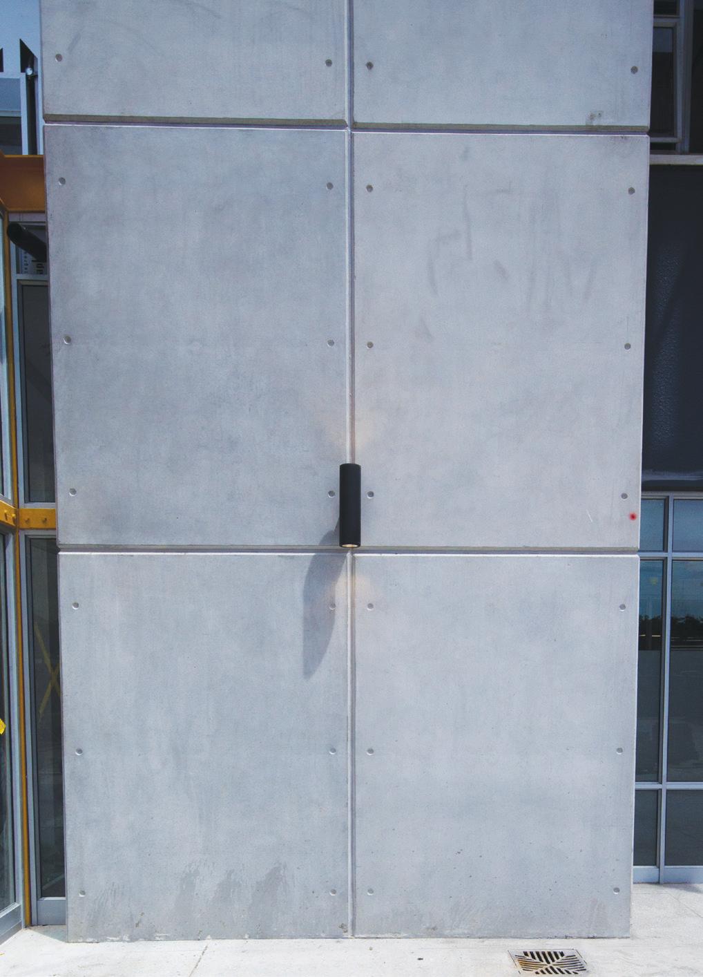
The panelling shortly after installation.
a point of interest at the building’s northern entrance and because precast concrete has a much cleaner finish than insitu concrete.
“The finish on Concrete Unit’s precast panels is beautiful and panelling emulates the facade of the New Paving Laboratory (NPL) which is adjacent to the engineering building. We established a language of materiality for the NPL which is being adopted for the engineering block’s northern façade. Moreover, we requested that the panels be cast with ferrule holes as cosmetic embellishments which mimic the holes in the in-situ concrete finish of the NPL,” said Zwarts.
Housing the building’s distribution boards, the shafts comprise reinforced concrete walling on the front and outer elevations, and reinforced concrete with a brick in-fill walling, on the inner-facing walls.
Edifice structural engineer, Ryno Thiart, said that one of the main challenges was establishing the most effective method of attaching the panels to the walling.
“We were fortunate in that the shafts are housed in a Reinforced Concrete (RC) frame which meant they had the strength to support the precast panelling. “Our design geometry embraced KMH Architects’ visual input as well as practical installation considerations, and was premised on a shared panel loading between the reinforced concrete corbels, attached to the bottom of the existing concrete shafts, and galvanised steel angle brackets, which were mounted on the shaft walling. The angle brackets were designed for lateral connectivity and for handling the panels’ vertical loading in the event that some loading would not be distributed to the concrete footings. In addition, the corbels were designed to support the total vertical panel loading. Apart from the base level panel sections which rest on the corbels, each panel section sits on the segment below through keyway joints cast into the panels.
“We kept the weight of the panels to a minimum to reduce the loading. And we made the panel walls a relatively thin 100mm because they are not subject to the same forces as the end sections which were required to be thicker for bracket hanging and inter-panel connectivity,” advised Thiart.
Once the ground level facade panels were installed by VBD Steel Construction, Concrete Units took laser levels and calculated bracket positions. This process was assisted by the fact that the building had been constructed to very tight tolerances in the 1970s.
“The structure and brickwork were within a 5-10mm tolerance which one rarely sees these days,” said Concrete Units production manager, Alwyn Carstens. “This meant our lines and levels worked out very well and allowed us in turn to operate within tight tolerances.”
Scaffolding with platforms in line with each segment was erected around the shafts which made the installation process relatively easy. A 25 tonne mobile crane hoisted the panels above the top of the scaffolding and lowered them between the scaffolding and the walling onto the angle brackets.
The panels were cast with corbels/beams which run the full width at the top of the panel and provide a 170mm anchor ledge for hanging them off the steel angle brackets. In addition, V-shaped grooves were cast into the top of the corbels and V-shaped ridges were cast into the bottom panel beams to facilitate the keyway connections. GVK contracts manager, Deon Terblanche, said that in order to achieve the shared load
One of the top level panels cast with a recess to fit around the concrete beam at the top of the building.
distribution between the brackets and the panels, HDPE shims were inserted between the brackets and the corbels.
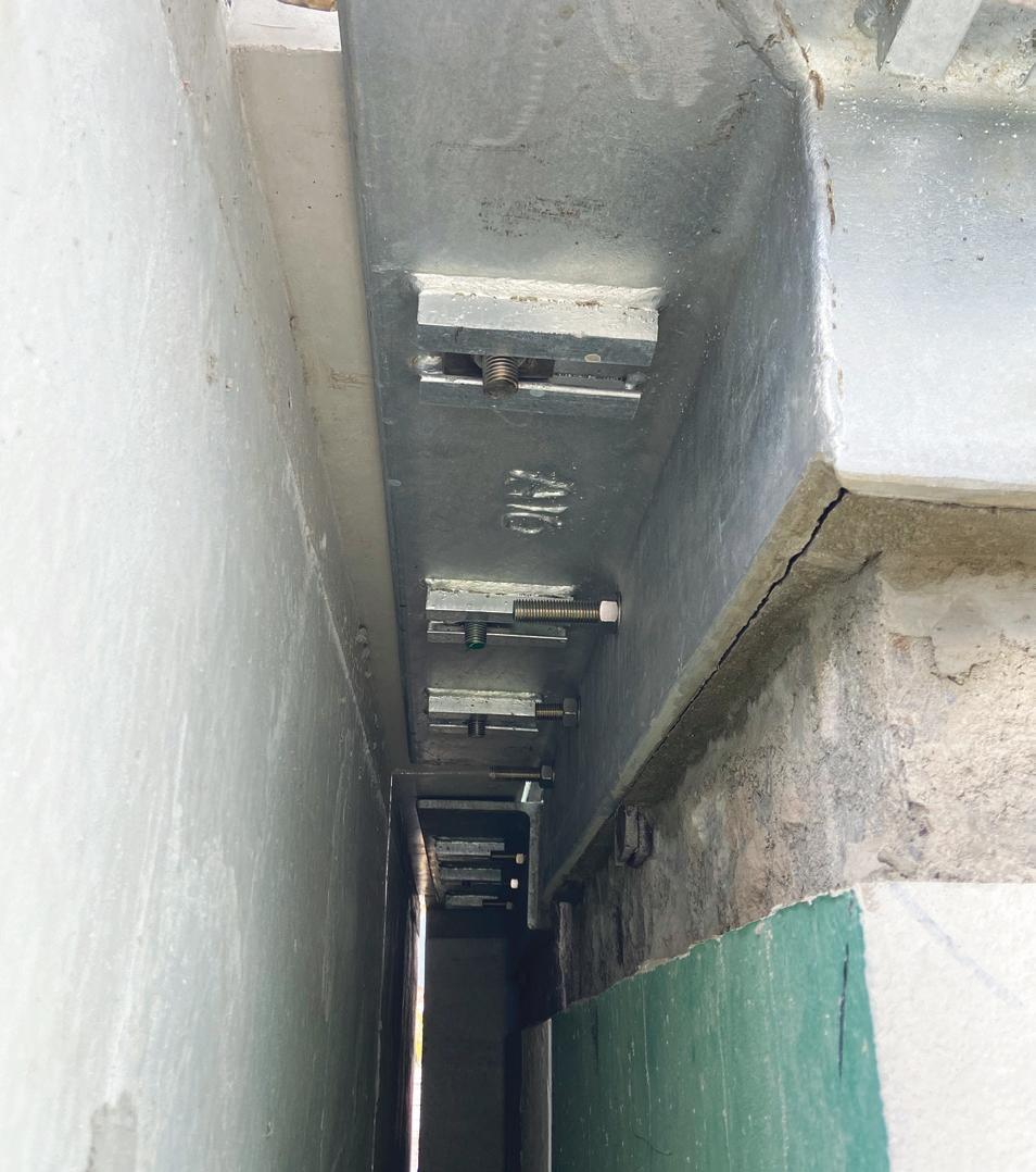
“Shim placement involved lifting the panels off the brackets to provide access. The brackets were installed 10mm below their designated levels to allow for the height and load-sharing adjustments. In addition, rubber sealing was used in the keyway joints to further assist with the alignment process and ensure tight joints.
“Once the panels were aligned they were permanently secured to the brackets with 20mm stainless steel bolts. Each bracket was purpose made, because once the panels were installed there was no space to secure the bottom nuts in position while the bolts were tightened from the top. To overcome this problem purpose-made square nuts were used; they were kept in position by steel guides welded to the underside of the angle and the angle bolt holes were slotted to allow for the lateral alignment and adjustment of the panels. Further bolt insertion flexibility was provided by Concrete Units casting extra-large 40mm bolt sleeves in the panel corbels,” said Terblanche.
The angle brackets were attached to the RC walls with stainless steel bolts. They penetrate through to the back of the RC walls where they are secured to purpose made steel square washers. In cases where the brackets were close to shaft corners, chemical anchoring was used.
The in-fill brick walls were not sufficiently strong to support the eccentric vertical panel loading, therefore channel brackets were attached on the inside of the building to two existing RC columns which flanked each infill wall. Stainless steel bolts were inserted through both sets of walling, fixing the external angle bracket to the internal steel channel. The brick walls were three-skinned and 330mm thick as opposed to the 220mm reinforced concrete columns on either side of them. Therefore the internal brick skin, three courses deep, had to be removed to enable the installation of the channel brackets. The voids between the brackets and the walls were filled with Sika grout to conceal the steel channels on the inside of the building.
A further complication occurred on segment eight of the outer shaft wall, where concrete beams intersected with the shafts. In this instance panels with recesses were cast to accommodate the beams.
Once all the panels had been installed they were capped with precast coping cast by Concrete Units. As well as being easy on the eye, the coping also prevents water seepage. Additional water-proofing was achieved by applying a Sika sealant to the horizontal and vertical panel jointing.
After gaining Edifice approval for the rebar layout, Concrete Units cast the panels with 40MPa concrete which was cured with a wax-based curing compound.
“We positioned the rebar in the centre of the panels to achieve 40mm cover. Three new moulds were utilized to achieve an off-shutter finish on the front face and all the sides. In addition we used 15x15mm chamfers on all the corners which created smooth edges and a groove which was filled with the Sika sealant.”
“After the panels were cast they were joined together at our factory to ensure that the front alignment was 100% and that the jointing worked correctly. Each panel had four lifting holes and we calculated the centre of gravity for each panel so that they hung vertically during installation,” said Carstens.
The panels were transported to site using special transport frames and every frame was vertically loaded with four panels. n
A freshly cast panel showing the V-shaped connection groove at the bottom of the panel.
PROJECT TEAM
Client Facilities Management Stellenbosch University Principal agent AL&A Architect KMH Architects Consulting structural engineer Edifice Consulting Engineers Main contractor GVK- Siya Zama Construction Panel producer Concrete Units Panel installation VBD Steel Construction Civil engineering SMEC Electrical engineer Triocon Electronic engineer TTA Fire consultant STAC Mechanical and wet services engineer BVi
Precast elements accelerate new Cape Peninsula reservoir construction
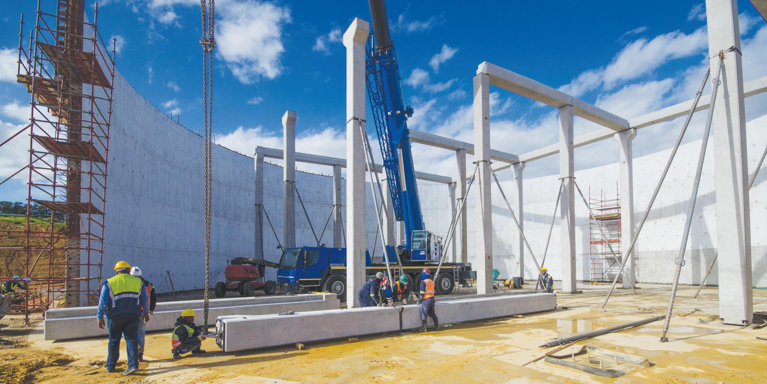
Using precast concrete, construction of a 15ML water reservoir is nearing completion on the Welmoed Estate adjacent to Blackheath, Cape Town. Built on behalf of Western Cape Human Settlements, the reservoir will feed the nascent 8 000 housing unit catalytic Welmoed Estate Development, formally known as Penhill, with its daily water requirements.
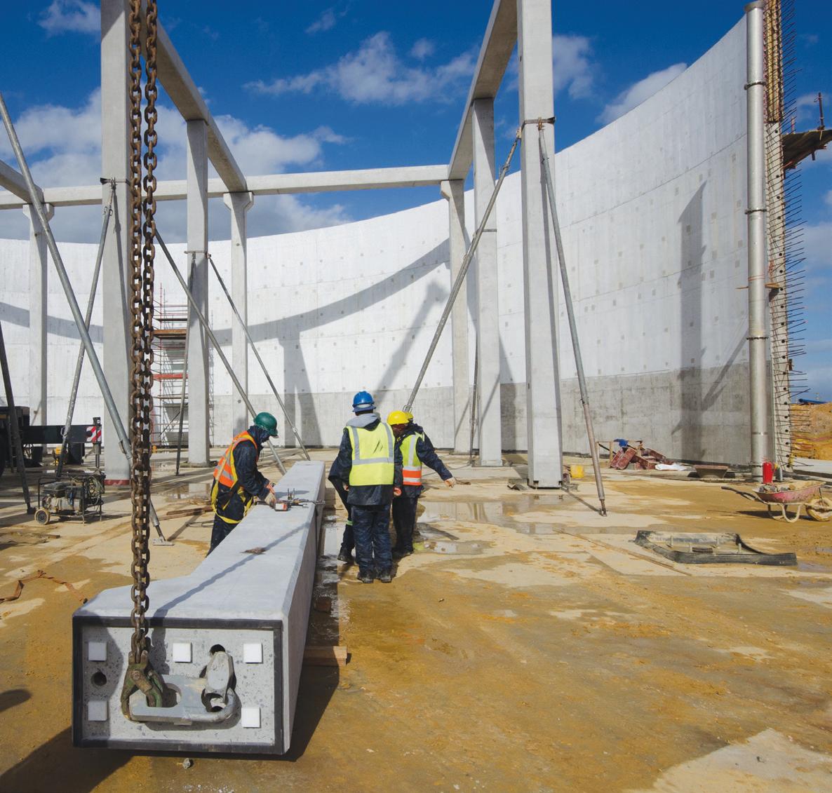
The water-storage facility combines precast and in-situ concrete construction; the columns, beams and hollowcore roof slabs are precast and the reservoir’s 12.5m high wall and its flooring were cast in-situ.
Designed by SMEC South Africa, the reservoir is being constructed by Exeo Khokela Civil Engineering Construction, which is performing the work on behalf of ASLA Construction, the main contractor for the construction of the civil services. The precast concrete elements were manufactured by Cape Concrete, a member of the Concrete Manufacturers Association.
The structure’s building sequence was as follows: construction of the ring-beam foundation and the flooring base layers; the insertion of elastomeric bearing pads on the ring-beams; casting of the walls in quarter sections; casting the column foundations together with the column bolting mechanism; installing the columns, roof beams and hollow-core slabs; sealing off the column bases with grout; completing the sections of the wall and casting the top floor surface; casting a concrete topping on the hollow-core slab roofing and covering it with aggregate.
The advantage of using precast concrete was amply demonstrated by the fact that the erection of the columns, beams and hollow-core panels took only eight days. Sixteen precast
columns with slight height variances around the 11.8m mark were installed within the reservoir walling to support the roof assembly. Column heights were varied to facilitate the structure’s four roof slopes.
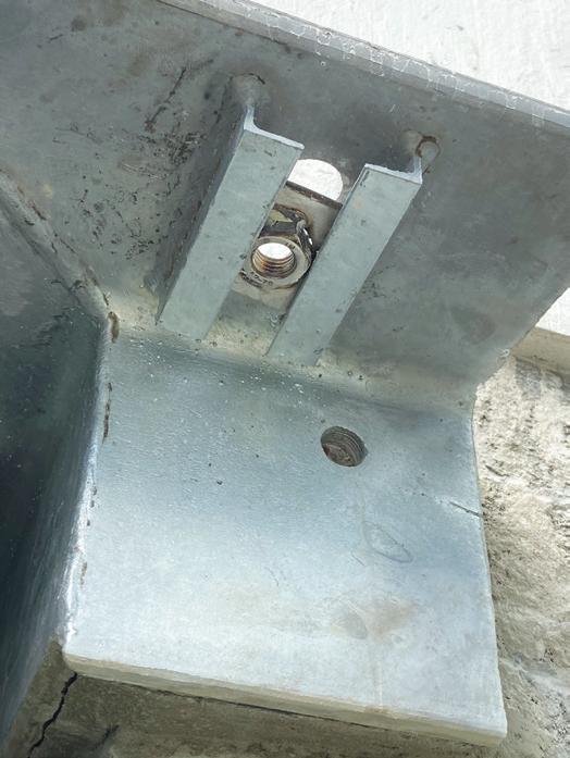
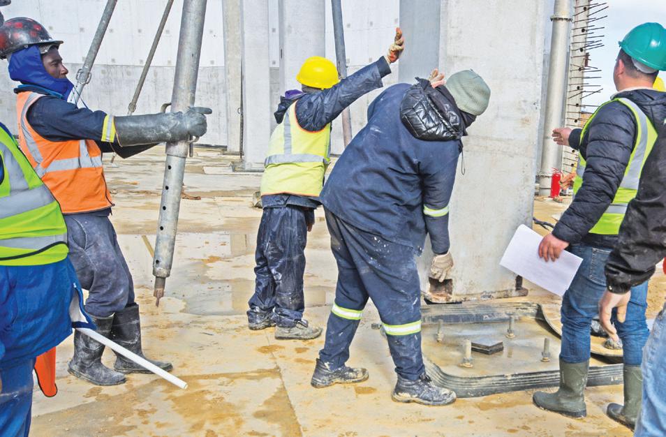
A mechanical nut-and-bolt connecting system was used to attach the columns to the foundations. Steel bolting cages comprising four 450mm x 30mm diameter anchor bolts welded to three 30mm steel plates were imbedded in the foundation concrete. In addition, 100 x 100 x 20mm anchor plates were welded to the bottom of each anchor bolt thus giving them additional purchase. The anchor bolts project 150mm above the column foundations for connecting into the column base plates.
Cape Concrete cast 30mm thick base plates into the base of the columns and 33mm holes were drilled into the corner of each steel plate; these slotted over the anchor bolts when the columns were lowered into position. Both the positioning of the anchor bolt cage in the foundation and that of the column base plate had to done with pinpoint accuracy to ensure that the anchor bolts and the base plate sleeves were easily aligned.
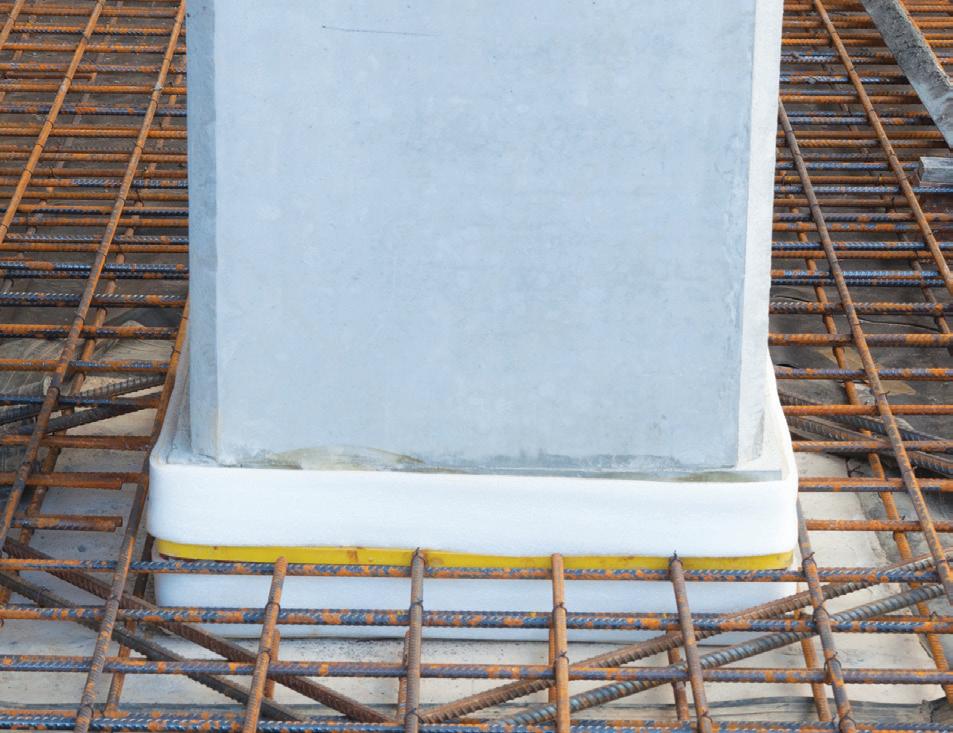
The columns were propped during installation and 150 x 150mm steel shims were used to stabilize the columns for the initial column load while they were aligned and adjusted to SMEC’s design height. A double-nut mechanism was used to achieve a perfect 90° alignment of the columns and the final load is shared by the bolting system and the shims. Once all eight nuts had been tightened, Sikaswell Water Stop was installed around the base of the columns and the cavity between the base and the top of the foundations was sealed off with high-strength non-shrink grout.
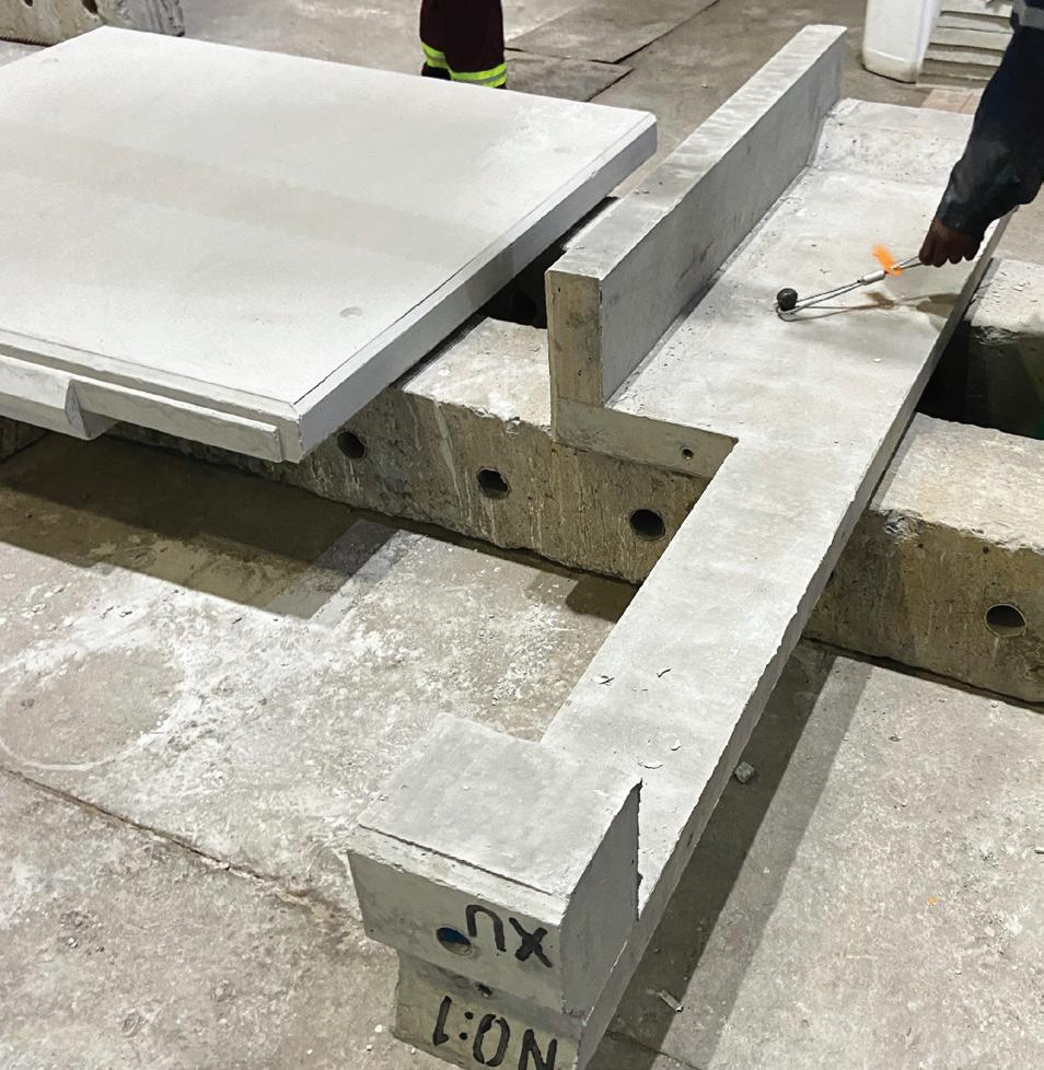
The roof framework comprised 18 precast beams mounted on top of the columns. Depending on the beam layout configurations, the columns were cast with either one or two corbels, and a few were corbel-free. The beams rest on four sets of HDPE packers which Cape Concrete had glued to the top of the columns to create a 25mm gap between the beams and columns for grout insertion. In addition, it lined the top of the columns with 30 x 30mm rubber edging to seal the grouting cavity.
The beam/column connections were further secured with Y25 dowel bars, 855mm long. These were inserted through 60mm corrugated metal sleeves which Cape Concrete had cast into the beams and the columns. At least two, and in some instances, three dowels were used for each connection. Once the dowel bars were inserted, grout was pumped into the sleeves from the top of the beams. A precast column is lowered onto the connecting bolts.
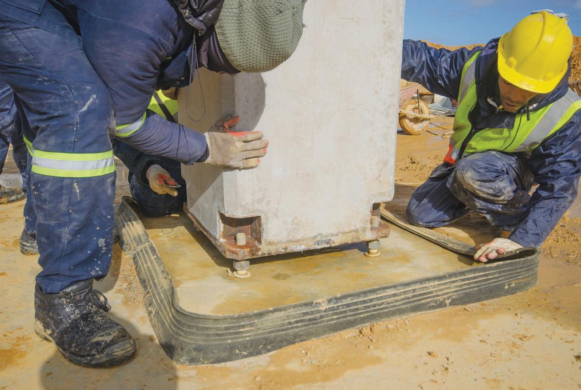
A grouted column base showing the yellow Sikaswell Water-Stop.
Cape Concrete director, Johan Nel, said combining a mechanical connection with a dowel connection made a lot of sense in this application.
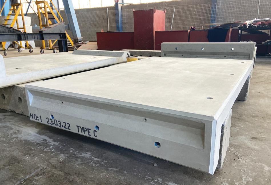
“The accuracy of mechanical connections means that once a beam is seated, dropping in a dowel becomes easy. But we had to scabble the surfaces where the beams and the columns met to roughen them for grouting.” Five beam types were used on the project. The longest were 8.8m and the shortest 7.58m apiece. The remainder were each 7.87m. The centre beams were tapered by 40mm to accommodate the slope of the roof, which because of its domed shape falls in four directions. Apart from the tapered beams, the beams measured 760mm (width) x 700mm (height). All were cast with right-angled recesses 200mm (depth) x 130mm (lip) to seat the hollow-core panels. This ensured that once installed, the top of the panels and the beams sat flush with each other.
Covering 1 200m² all told, the panels were laid beam-tobeam in the central rectangular section of the roof structure and from beam-to-wall. They were mounted on elastomeric bearings to allow for the thermal expansion and contraction of the roof. Dimensions of the beam-to-beam panels were a standard 1200mm x 200mm. But panels which span from beam-to-wall all vary in length owing to the fact that the