


| FEBRUARY 2023 JUNE 2023 • VOL. 13, NO. 3 THE TECHNICIAN’S RESOURCE 5 ASP FEBRUARY 2023 EV DIAGNOSTICS TICS GAS|DIESEL+HYBRID|EV DIAG MAXISYSULTRAEV EVDIAGBOX+5-IN-1VCMI INCLUDESALLFEATURESOFTHEULTRA ADVERTISEMENT
EV DIAGNOSTICS
OSTICS EV DIAGN
DIAG
GAS|DIESEL+HYBRID|EV
MAXISYSMS909EV
EVDIAGBOX+VCI INCLUDES ALL FEATURES OF THE MS909

MAXISYSULTRAEV
EVDIAGBOX+5-IN-1VCMI INCLUDESALLFEATURESOFTHEULTRA


• DETAILED BATTERY PACK DIAGNOSTICS
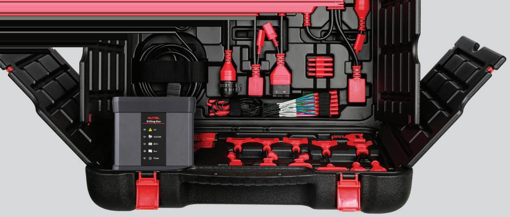
• STATE OF CHARGE & STATE OF HEALTH ANALYSIS
EVDIAGKIT


• SPECIALIZED BATTERY ANALYSIS VIA BMS


• DETAILED CABLE CONNECTION DIAGRAMS
UPGRADEYOUR MS909,MS919,ULTRA
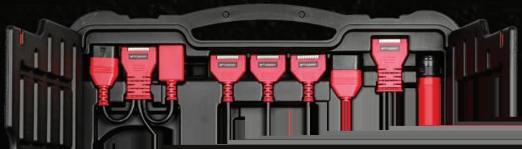
KIT INCLUDES
EVDiag Box & Adapters for Specific Electric Vehicles to Perform Battery Pack Analysis. (ConnectstoMaxiFlashVCIorVCMI)
WEB: AUTEL.COM | SUPPORT: 1.855.288.3587 EMAIL: USSUPPORT@AUTEL.COM FOLLOW US @AUTELTOOLS
WHY DOESN’T THE ENGINE CRANK OVER?


Tips for when the vehicle won’t start


SERVICING ACTIVE SHUTTER SYSTEMS


TESTING 3-PHASE HIGH VOLTAGE ELECTRIC MOTORS

UNLOCKING CHRYSLER DIAGNOSTICS


JUNE 2023 • VOL. 13, NO. 3
THE TECHNICIAN’S RESOURCE


www.PerfectstopSummerPromo.com FOR OFFICIAL RULES, VISIT WWW.PERFECTSTOPSUMMERPROMO.COM. 2023 Aftermarket Auto Parts Alliance, Inc. No purchase necessary. Void where prohibited. Promotional images may not reflect actual prizes. Logos and trademarks are the property of their respective owners. $25,000 Also Giving Away, $25,000 in 150 ancillary gift card prizes WINNERS 6 Technicians enter for your chance to win the powersports vehicle of your choice and up to $25,000 with Perfect Stop®. ENTER WIN! FOR YOUR CHANCE TO STARTs JUNE 1st 2023 ENDs JULY 31st 2023

JUNE 2023 | ASP 3 Departments STRAIGHT TALK Safety and Maintenance Tips You & your tools need year-round care TECH TIPS Help with no-crank engines and park assist sensors TECHNICAL SERVICE BULLETINS Buick sedans, Ford and Chevy trucks and more AD INDEX Technical WHY DOESN’T THE ENGINE CRANK OVER? The basics and vehicle-specific tips when the vehicle won’t start SERVICING ACTIVE SHUTTER SYSTEMS AGS reduce aerodynamic drag and aid engine temperature TESTING 3-PHASE HIGH VOLTAGE ELECTRIC MOTORS Conduct four stator checks in 30 minutes CHRYSLER DIAGNOSTICS Scan tool unlocks robust data and tests 04 07 41 42 08 14 24 29 CONTENTS June 2023 Vol. 13, No. 3 08 14 24 29 COVER PHOTO CREDIT: 221246082 © ROMAN CHAZOV | DREAMSTIME.COM Auto Service Professional > The Technician’s Resource For Owners For Managers For Technicians
Safety and Maintenance Tips

You & your tools need year-round care
NEVER TAKE YOUR HEARING FOR granted. It just takes one exposure to a loud noise to damage or even kill your eardrum nerves. Anyone who shoots fi rearms at a range is all too aware of this, which is why any intelligent shooter always wears some type of ear protection.
While gunshots are not the norm in your shop (at least I hope not), certain situations can pose serious hearing damage: loud engine backfire, an inflating tire popping loose and “exploding,” use of an air hammer or any other loud pneumatic tool. Any noise over 70 decibels can be harmful. Anything above 120 decibels can cause immediate hearing damage.
Any type of hearing protection is better than nothing (passive ear muffs, for example). If you’re performing a task where you know you’ll be exposed to serious noise levels, consider the use of electronic active/noise canceling ear protection. While passive ear protection muffles all sounds (and makes it hard to hear someone talking), electronic noise canceling ear protection allows you to hear normal conversations and sounds, and maintain normal situational awareness. But almost immediately (within 0.02 seconds), it super-dampens a high decibel noise when it occurs. Basically, the best of both worlds.
This type of hearing protection is available in the form of a “traditional” muff (cup on each ear, connected by an overhead band) that features electronic noise canceling circuitry, as well as ear “buds” that are Bluetooth compatible (programmed/activated by a smart phone or a wristwatch controller). If your shop environment is such that you feel your hearing is at risk, seriously consider one of these options. Once the eardrum is damaged, there’s a good chance the damage is permanent.
DON’T IGNORE YOUR TORQUE WRENCHES
It’s easy for many to forget the need to have torque wrenches checked for calibration on a regular basis. Through use, torque wrenches can lose their calibration, a factor that many tend to ignore, forget, or be unaware.
Any noise over 70 decibels can be harmful. Anything above 120 decibels can cause immediate hearing damage.”
Any type of torque wrench, whether micrometer “click” style, dial or even digital, should be recalibrated once per year or after about 5,000 cycles, whichever comes first. There are several sources for torque wrench recalibration, including either the wrench manufacturer or independent shops (Angle Repair in Beckley, W. Va., for example). If torque wrench condition is ignored, accuracy will be affected and eventually you can easily find yourself under or over-tightening without realizing it. The cost of recalibration is minimal (usually about $25 or so) and turnaround time is typically pretty quick. Once recalibrated, the service shop should attach a sticker indicating the date of service, which will help remind you of the need for the next calibration.

4 ASP | JUNE 2023
STRAIGHT TALK
MIKE MAVRIGIAN EDITOR

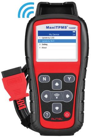


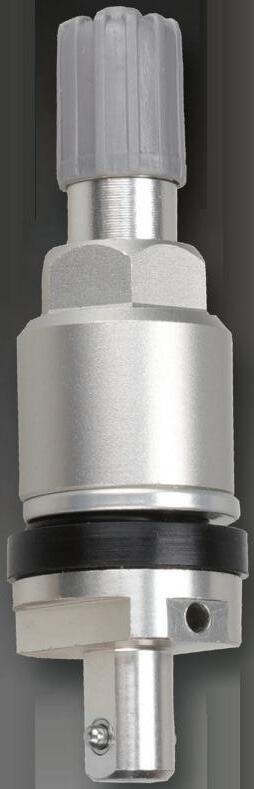
JUNE 2023 | ASP 5 TPMS SERVICE TOOL • Perform OBDII Relearns • Four 1-Sensor Programming Methods • FREE Updates for the Life of the Tool TS508WF TPMS DIAGNOSTICS & SERVICE • Print/Email/Text TPMS Health Report • OLS, BMS, SAS, EPB Service Resets • FREE TPMS Updates for the Life of the Tool ITS600 VIA WI-FI NO PC NEEDED AFTERMARKET SENSOR ALUMINUM RUBBER > ORIGINAL EQUIPMENT FIT FORM & FUNCTION PROGRAMMABLE UNIVERSAL TPMS MAX SIGNAL STRENGTH 99 % VEHICLE COVERAGE FAST INSTALLATION PRESS RELEASE INTERCHANGEABLE VALVE STEMS ® 1 SKU SENSOR INVENTORY : 314.9MHZ, 315MHZ & 433MHZ WEB: AUTEL.COM | SUPPORT: 1.855.288.3587 EMAIL: USSUPPORT@AUTEL.COM FOLLOW US @AUTELTOOLS
OnlIne
THE TECHNICIAN’S RESOURCE

3515 Massillon Rd., Suite 200, Uniontown, OH 44685
(330) 899-2200, fax (330) 899-2209
Website: autoserviceprofessional.com
PUBLISHER
Greg Smith / gsmith@endeavorb2b.com (330) 598-0375
EDITORIAL
Editor: Mike Mavrigian mmavrigian@endeavorb2b.com
Managing Editor: Joy Kopcha jkopcha@endeavorb2b.com / (330) 598-0338
Associate Editor: Madison Gehring mgehring@endeavorb2b.com / (330) 598-0308
PRODUCTION
Art Director: Molly VanBrocklin
Production Manager: Karen Runion krunion@endeavorb2b.com / (330) 736-1291
CONTRIBUTORS
Je Taylor, Diagnostics & Drivability Specialist
Bill Fulton, ASE Master Tech
Craig Van Batenburg, EV Technology
ADVISORY BOARD
Chris Chesney, Repairify
Jake Sorensen, McNeil’s Auto Care
Seth Thorson, Eurotech Automotive


Donny Seyfer, Seyfer Automotive
Bill Fulton, ASE Master Tech
MARKETING STRATEGISTS
Dan Thornton / dthornton@endeavorb2b.com (734) 676-9135, mobile (734) 626-4950
Bob Marinez / rmarinez@endeavorb2b.com (330) 736-1229
ASP’S WEBSITE IS THE GO-TO SITE FOR VEHICLE INFORMATION 24/7.

Turn to it any time you need the latest technical service bulletins, in-depth technical articles and the newest products. Our site also features news from suppliers and manufacturers to keep you up-to-date on what’s happening in the automotive industry.
Plus, go to our website to renew your subscription to ASP, read the digital version of each issue and sign up for a free subscription to our weekly eNewsletters!
Marianne Dyal / mdyal@endeavorb2b.com (706) 344-1388
Sean Thornton / sthornton@endeavorb2b.com (269) 499-0257
Kyle Shaw / kshaw@endeavorb2b.com (651) 846-9490
Martha Severson / mseverson@endeavorb2b.com (651) 846-9452
Chad Hjellming / chjellming@endeavorb2b.com (651) 846-9463
ENDEAVOR BUSINESS MEDIA, LLC

CEO: Chris Ferrell
President: June Gri n
CFO: Mark Zadell
COO: Patrick Rains
CRO: Reggie Lawrence
Chief Digital O cer: Jacquie Niemiec
EVP Transportation: Kylie Hirko
Vice President - Vehicle Repair Group: Chris Messer
6 ASP | JUNE 2023
VISIT AUTOSERVICEPROFESSIONAL.COM TODAY
TECH TIPS
NO-CRANK SILVERADO
This tip involves a 2013 Chevy Silverado 2500 equipped with a 6.0L gas engine that had a no-crank condition. After initially checking battery condition and then checking all grounds — which is what we initially suspected — we found no faults. To make a long story short, the problem occurred when the customer over-filled his fuel tank. (When the gas pump clicked off, he kept adding fuel.) The extra fuel washed the fuel tank pressure sensor, which basically killed the sensor. With a dead sensor, the management computer interprets this as a fuel tank pressure problem and prevents cranking. The signal voltage to the sensor should be 5 volts, but when checked it showed only about 0.4 volts. With the sensor connector disconnected (it is located on top of the fuel tank and there was enough access to reach in and disconnect it), the signal wire showed a normal 5 volts and the engine cranked and started. The fix: replace the fuel tank pressure sensor. That requires either removing the truck bed or dropping the fuel tank for access. The sensor simply pushes into a grommet.
MAZDA BUZZ
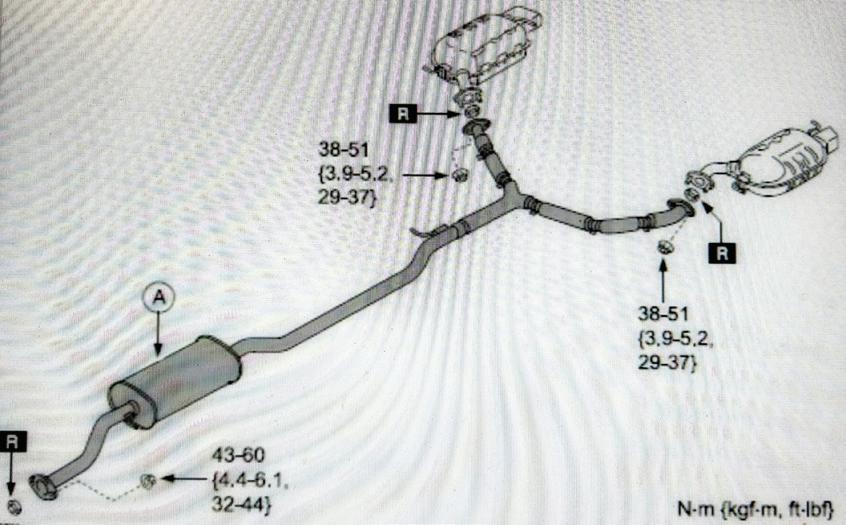
If you run into a 2010-2015 Mazda CX-9 with a rattle/buzzing noise with the engine at around 1,800 RPM, check the exhaust system pre-silencer (muffler). The lower side of the pre-silencer may be thermally deformed due to insufficient weld spots. The deformed portion may resonate gas pulsations which cause the noise. Mazda now has a reinforced plate added to the pre-silencer to correct this problem. Replace the pre-silencer with P/N CA11-40-300C.
GM PARK ASSIST SENSORS
The park assist sensors for front and rear park assist systems on some 2018 and later GM vehicles may be damaged due to a number of conditions. Check for a sensor with visible stone chips/membrane damage. Also check sensors for connector damage and for broken retaining tabs.
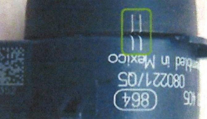
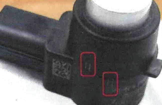
Note that the sensors feature dual alignment marks. These marks should be aligned. Do not twist the sensor to remove the painted cap. A twisted sensor with marks misaligned can be caused during sensor removal or installation. Also, sensors feature painted caps. Do not refinish previously painted caps. Excess paint buildup will cause the sensor to be inoperative.
JUNE 2023 | ASP 7
From no-crank Silverados to GM park assist sensors
Example of correctly aligned marks. (courtesy GM)
Example of mis-aligned markings. (courtesy GM)
Replace the pre-silencer, seen here as part “A.” (courtesy Mitchell 1)
Why Doesn’t the Engine Crank Over?
The basics and vehicle-specific tips when the vehicle won’t start
 BY JEFF TAYLOR
ANALYZING THE CAUSE OF A NOstart vehicle can be complicated, as there are many variables to consider. Vehicle no-start situations often fall into two categories: cranking nostart or no-crank when the ignition key is turned or when the start button is pushed.

We are going to examine the no-crank, no-start scenario and look at some of the more common issues that can cause this situation. In this scenario the starter motor does not crank the engine over when the operator asks it to.
Typically, the no-start/no-crank diagnostics will follow one of three paths: a dead or weak battery, the starter motor solenoid clicks but the starter motor doesn’t function, or the starter solenoid doesn’t receive a “crank the engine” command voltage signal.
Even before we attach a scan tool to the vehicle to start our diagnostics, we need to perform a good visual
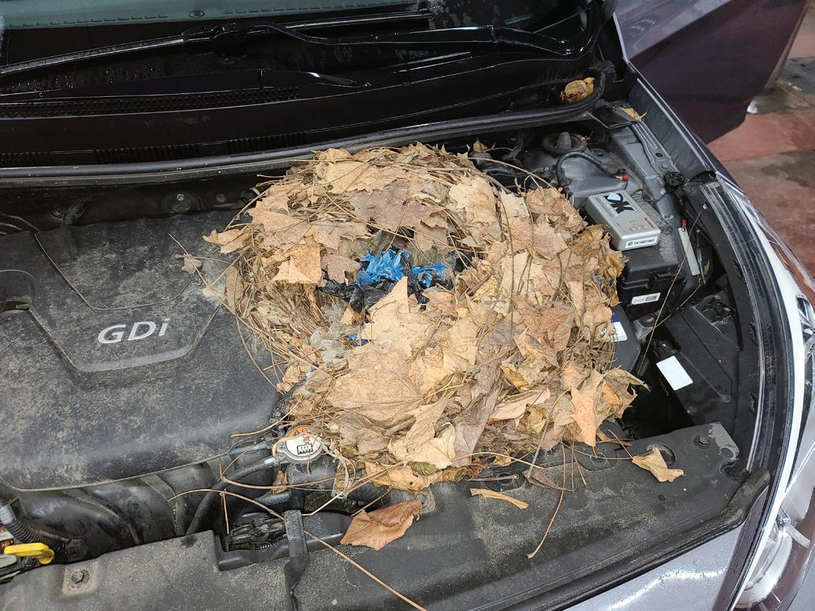
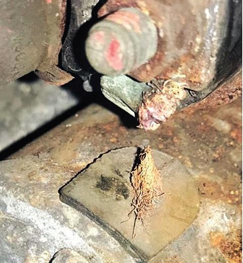
inspection and pay attention to the most obvious areas first. Is the battery fully charged and able to supply the needed voltage to the starter motor through clean and tight battery connections? Is there a rodent’s nest under the hood that has damaged wiring? Have there been earlier repairs on the starting system? Are there aftermarket accessories installed? The power of a thorough visual inspection cannot be underestimated.
When starting any diagnostics, always be sure to check for TSBs first. Certain 2018-2023 Honda SUV models have an issue with water intrusion into the starter motor that can freeze in the winter and prevent the starter motor from functioning. This issue could be overlooked or hidden if the vehicle is in the shop and thaws before the diagnostics are performed. The fix is to replace the starter motor with a modified design.
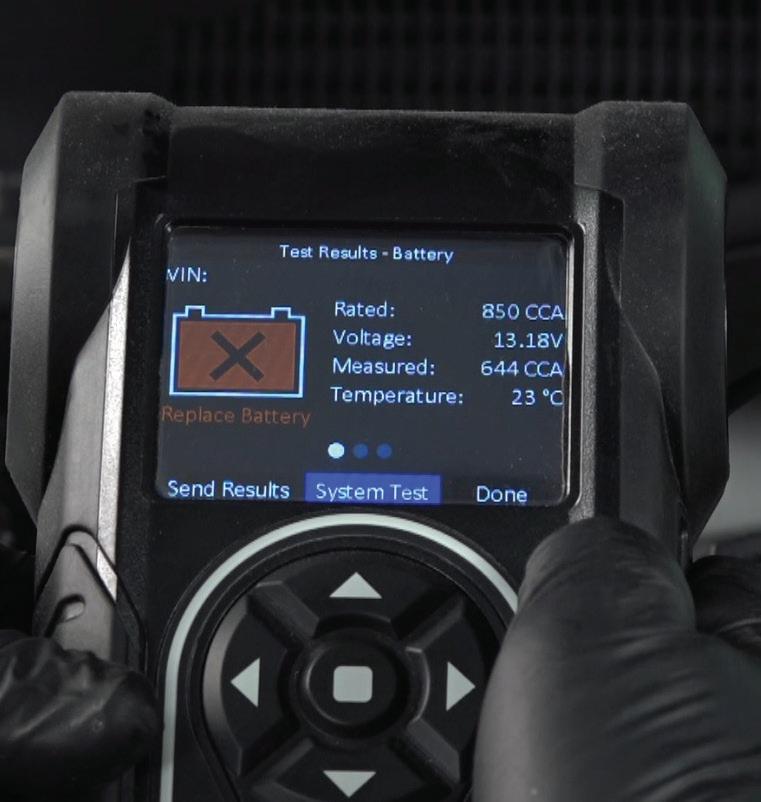
Start with the battery. The proper testing of the battery should be the first step in our diagnostics. Without an adequate supply of energy from the battery the

8 ASP | JUNE 2023
NO-START VEHICLES
We put our trust in you every day. Thank you for your dedication.


JUNE 2023 | ASP 9
www.FederatedAutoParts.com
SALUTES Automotive Service Professionals
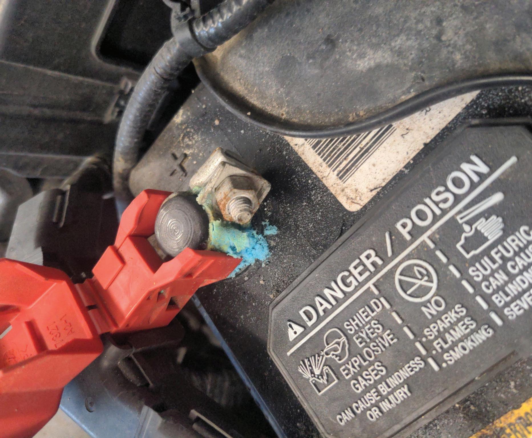
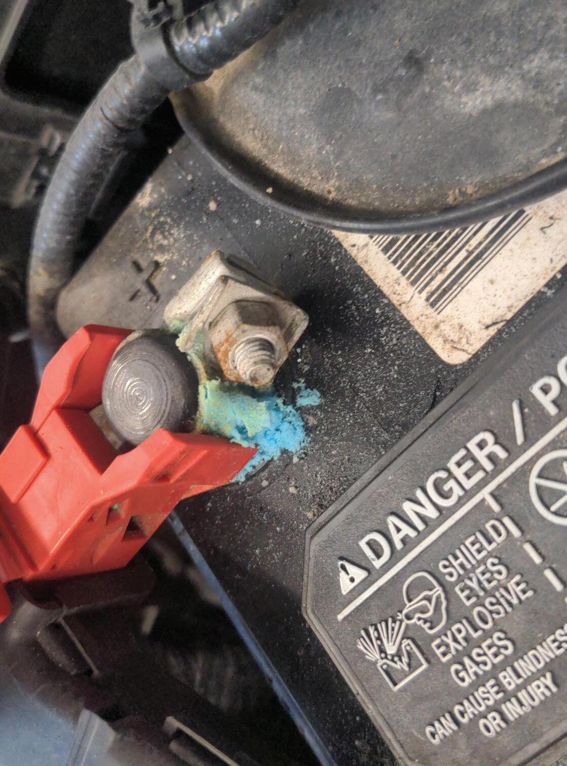
engine will not start. Clean and tight battery connections are often overlooked when diagnosing, but this inspection is crucial, especially with so many batteries being remotely located in various parts of today’s vehicles. Evaluating the battery with the proper battery tester is important, and the use of a digital tester that will compensate for battery temperature and the specific battery design is now the preferred method. The best place to accurately evaluate a battery when dealing with a no-start is directly on the battery’s negative and positive terminals. Often getting to the battery connections can reveal the issue (think of the Dodge Journey battery in the left front fender location). If we have ruled out the battery as the cause of our no-crank situation, we will move on to the next step.
What if the starter motor is not receiving the command to crank over the engine? When the vehicle operator wants the engine to start, a low-current control signal will be sent to activate the starter solenoid. But if that activation signal isn’t sent, the engine won’t crank.
The PCM will typically be the module that will supply power to the starter activation control circuit (often via a relay), but it will be based on decisions and data from other modules on the vehicle. The security system is heavily involved. It will confirm that the correct key, key fob, key card or cell phone device (digital key) is valid and confirm that the operator is allowed
to request an engine start. Other components involved in the starting system are simpler, and the brake and clutch pedal inputs are important for safety. These inputs can be verified using a scan tool and looking at the proper data PIDs.
The starting system diagram for a 2018 F150 V63.5L highlights the interconnection of several modules to enable the cranking of the engine. The Body Control Module (BCM), Powertrain Control Module (PCM), Passive Anti-Theft System (PATS), Gateway Module, Integrated Keyhead Transmitter (IKT), Ignition Switch/Push Button Start, Radio Transceiver Module (RTM), Audio Front Control Module (ACM) and inputs from the automatic transmission must all share and agree on various pieces of information — before the starter motor will crank the engine.
Example: Once the PCM on a Ford F-150 receives all the correct inputs (park or neutral inputs from the automatic transmission) and data from other modules, the PCM will supply voltage to the starter relay and the ACM will supply the ground to the starter relay coil. This will activate the relay and supply voltage to the starter solenoid to crank the engine. Note that the F-150 is controlling both sides of the starter relay via two separate modules.
10 ASP | JUNE 2023 NO-START VEHICLES
Don’t underestimate the power of a visual inspection. This squirrel’s nest was the cause of the no start on this Hyundai Elantra. (all photos by author)
The energy to crank the engine comes from the battery, and proper testing of the battery is a first step in diagnosing a no-crank situation.
Some 2012-2017 VW Beetles and Jetta models have an issue with the push-button start button itself, creating a no-crank, no-start condition. These VWs typically will crank fine with the switch electrically connected and removed from the dash and held in your hand when activated.
There are many things that can cause the crank activation signal not to be sent to the starter motor. Blown fuses, pitted and defective relays, corrosion, chewed wires and melted terminals in fuse/relay boxes can often be found. The addition of aftermarket security systems, remote start units, tracking and disabling devices can be harder to find, but are often spliced into the starter control signal system. If these units fail, they can easily cause a no-crank situation with no codes or wiring diagrams to aid in the diagnostics. A non-OEM key fob is often a good sign of aftermarket security and remote start systems, which are known to cause no-crank issues.
If we have verified that the starter solenoid is receiving the correct signal at the starter motor, we can move on to the last step in the no-crank, no-start diagnostic.
What if the starter motor is unable to crank the engine, but the starter solenoid clicks? Ensuring that the crankshaft will turn may sound simple, but a seized engine, a seized A/C compressor or other seized rotating part, linked to the engine, can easily stop a starter motor from cranking an engine.
After verifying the crankshaft will turn, we need to confirm that the starter motor has a good positive battery feed and a good ground circuit. Voltage Drop (VD) testing is the best method to verify any issues in the voltage supply and ground circuits.
The VD testing exposes corrosion or excessive resistance that may not be visible. The battery feed cable to the starter motor should have less than a 0.5volt VD when tested. The negative side should have the same reading: 0.5-volt VD.

If the VD is above 0.5V on either side during testing, either the cable is bad or there is a corrosion issue that will need to be addressed. If the readings are good and less than 0.5-volt VD on both sides, the starter motor is the likely culprit and needs to be changed (after double checking the starter control signal).
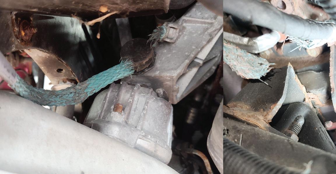
Positive and negative starter cables and connections aren’t the only area where corrosion can cause a no-crank, no-start. The use of environmentally friendlier road clearing and de-icing agents such as magnesium chloride and calcium chloride-based products has led to the accelerated corrosion of metals on vehicles, especially copper. The often-unprotected braided copper cable that supplies battery voltage from the starter solenoid to the starter motor field windings can be subjected to this accelerated corrosion. The corrosion of this braided copper cable can eventually lead to a total starter motor failure.
Finding the failure of this part isn’t always straight forward, as many starter motors are not easily visible. If you can see the starter motor when the start
JUNE 2023 | ASP 11
Performing a full system scan is vital in the diagnostics of a no-crank scenario with so many different modules being required to allow the starter motor to crank the engine.
The starter motor needs to have a good, low resistance ground circuit for proper operation, and the braided chassis ground is an often-overlooked cause of a no-crank issue.
command is sent, you may see sparks during the first solenoid connection. Or, you may be able to see the melted, broken or separated braided copper cable. (Carefully wiggling the cable may expose the corrosion failure if you are able to access the starter visually to confirm your diagnostic.) Repairing this cable is typically addressed by replacing the entire starter motor.
But these aren’t the only braided copper cables on the vehicle that can cause the starter motor not to function due to corrosion. Braided copper chassis ground straps that are used in various areas of the vehicle are also subject to corrosion. Many GM trucks and vans, various BMWs and Mini Coopers fall victim to the corrosion of their braided copper ground straps. The results of this ground side corrosion can cause no-start, no-crank failures or voltage drops that cause slow cranking, stalling, multiple DTCs, warning lights, drivability issues and other concerns.
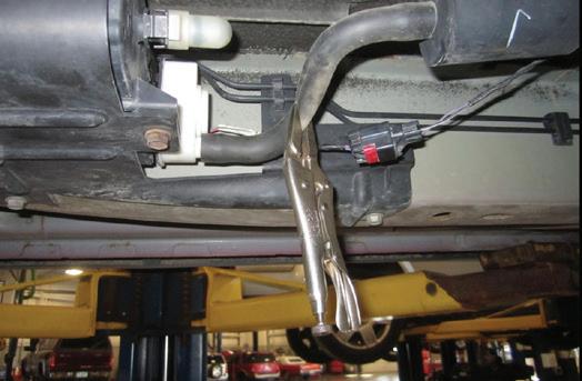
Certain 2014-2018 GM Sierra pickup trucks have an issue caused by the air conditioner drain dripping on the chassis ground connection on the vehicle’s frame, which causes cable and connection corrosion. These GM truck ground cables can also corrode inside the protective plastic shield and often look swollen at the point of corrosion. The fix is to clean the connection to
12 ASP | JUNE 2023
NO-START VEHICLES
Clean and tight battery connections are critical and should be confirmed early in the visual inspection of a no-crank complaint.
The corrosion of the cable that supplies voltage to the starter motor field windings is an issue, and a major cause of starter motor failure in areas that use road clearing chemicals.
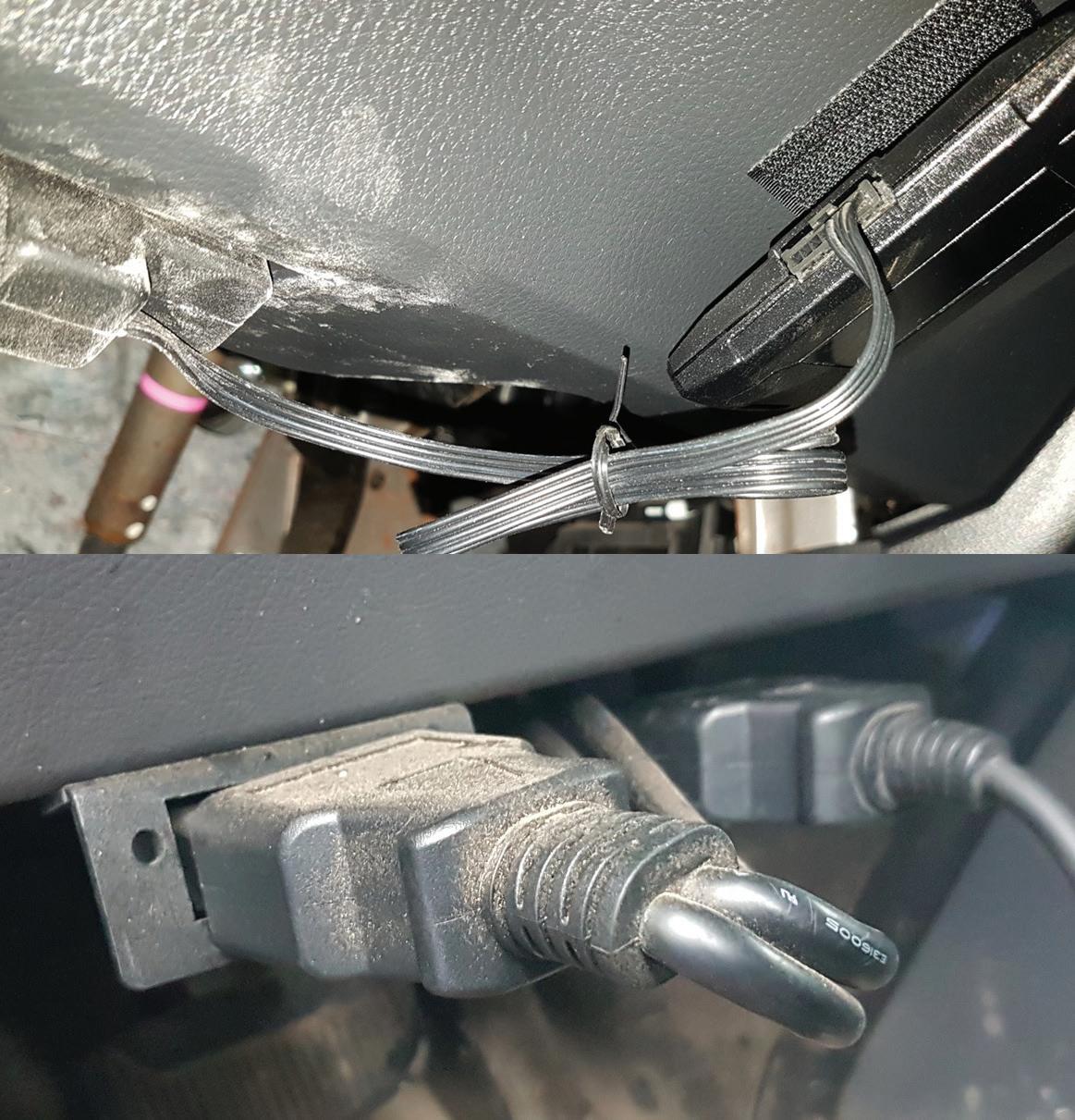
Inspecting the DLC for aftermarket trackers and other devices is a must when diagnosing a no-crank problem. These were easy to identify and remove; others are much more difficult to see or detect.
the frame or replace the main chassis battery ground cable/battery sensor module assembly.
Certain BMW models used a braided copper cable between the engine/transmission assembly and the chassis. Often this ground cable, on the right side of the chassis, behind the right front wheel, can’t be seen easily until the large under-engine shield is removed. Once the shield is removed, these BMW cables often corrode to dust when touched. This corrosion may result in a no-crank situation, or it could cause module communications issues, warning lights and electronic transmission range issues — often leading to misdiagnosis.
Performing a voltage drop across these connections is the best way to verify the issue, especially if the cable looks OK visually, as these vehicles all have remotely mounted batteries.
Diagnosing a no-crank situation today is going to require a scan tool, and an up-to-date information system that will supply the needed starting system wiring diagrams, relay and fuse locations. When tackling a no-crank diagnostic, don’t forget to look closely for non-factory installed security systems, DLC-attached tracking devices, and other aftermarket installed components that could be interfering or inhibiting the crank signal command.
Performing a full system scan of all the vehicle’s modules is crucial, due to their heavy interdependence. A DTC in a seemingly unrelated module could be involved in the cranking of the engine, and that module may have set a DTC that could help diagnose the no-crank issue. Understanding how the system is intended to function is important, and a look at the wiring diagrams often shows the functionality. The F-150 is a good example of this with the PCM supplying the power and the ACM applying the ground for enabling the starter relay operation.
Jeff Taylor boasts a 30-plus year career in the automotive industry as a fully licensed professional lead technician. Jeff works for the CARS Training Network Inc. in Oshawa, Ontario, Canada. He is also heavily involved in government focus groups, serves as an accomplished technical writer and he has completed in international diagnostic competitions as well as providing his expertise as an automotive technical instructor for a major aftermarket parts retailer.

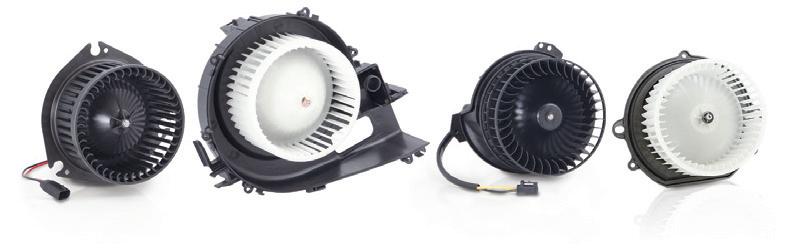
Continental delivers the exact replacement blower motor you’ll need to restore original cooling performance. Built with unsurpassed quality and reliability for OE vehicle-specific fit and performance, every motor features true OE connections and mounting flanges for easy and for trouble free install. No flying leads or wire splicing. All wheels included.
JUNE 2023 | ASP 13
the right part:
HVAC
–
it
with the right part.
Find
www.continentalaftermarket.com Continental
motors
Do
right
2306ASP_ContinentalCorp.indd 1 4/26/23 8:27 AM
It’s not something even the most seasoned tech may have looked at.
Servicing Active Shutter Systems

AGS reduce aerodynamic drag and aid engine temperature


 BY MIKE MAVRIGIAN
ACTIVE GRILLE SHUTTERS (AGS) ARE featured in a number of domestic and import brands and models of vehicles, dating back to approximately 2005. In essence, this is simply a shutter (louver) assembly located behind the grille, powered by an electric motor and controlled by the engine temperature signal from the coolant temperature sensor. Sometimes active grille shutters are referred to as radiator airflow shutters, active air shutters, active aero louvres, electronically controlled air shutters and electronically controlled aero shutters.
In simple terms, the active grille shutter assembly features a series of horizontal shutters (louvers) that open and close, much like a set of blinds on a window in your house. Instead of requiring manual operation, a controller motor performs the task based on a programmed set of operating conditions. And instead of adjusting the amount of light that passes through a window, the active grille shutters adjust the amount of airflow that enters through the radiator and into the engine bay.
When the engine is “cold,” upon initial startup, the louvers close in order to help the engine reach operating temperature more quickly, and they open when more airflow is needed. The reason for active shutters is two-fold: to enhance aerodynamics (instead of oncoming air moving into the engine bay, the closed shutters help to divert air over the vehicle) and to increase engine efficiency for improved fuel economy and lower tailpipe emissions by helping the catalytic converter light off sooner after initial startup. At low speeds,
14 ASP | JUNE 2023
ACTIVE GRILLE SHUTTERS
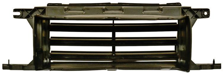
Example of replacing an active shutter. (courtesy Dorman)


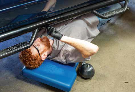


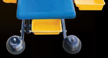

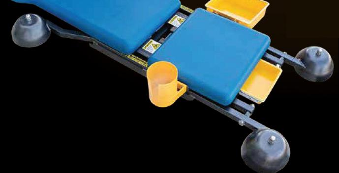


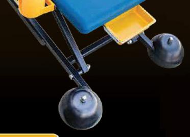


WORK MEETS COMFORT ROLLING CREEPER SEAT CONVERTS FROM HIGH TO LOW LOCKING HEIGHTS UP TO 5 The ergochairTM is the adjustable height rolling work seat which will make performing awkward work tasks ergonomically easier and safer. This comfortable creeper seat offers a full range of mobility, increased productivity, and reduced fatigue. To Learn more visit www.bendpak.com/ergochair 1-800-253-2363 • WWW.BENDPAK.COM ©2023 BendPak Inc. All rights reserved. NEW LEARN MORE ALL-IN-1 SHOPPING REV UP YOUR SAVINGS! ! © 2023 Wrenchers LLC. All Rights Reserved. 1-800-261-7729 Ask about our price promise guarantee. Call Now for a FREE catalog!
A COMPLETE LINE OF masterpro® finishing pads


Get the right finishing pads for every step of the refinishing process.


AVAILABLE EXCLUSIVELY AT
depending on engine temperature, the louvers may be closed or open. At freeway speeds, the louvers tend to close to increase aerodynamic efficiency.


It should come as no surprise that potential failure problems can occur if the shutters do not function properly. There may be problems due to jammed louvres (ice/snow buildup or dirt/debris accumulation), if the vehicle experienced a front-end collision, or if the engine temperature sensor had an issue.
The most common issue involves the active grille shutters becoming stuck — either open or closed. This may be due to a failed motor or the mechanical linkage between the motor and shutters has failed. Or, the electrical signal at the motor may be faulty. If the shutters are mis-aligned (due to manufacturing defect or the result of a collision, mishandling or other damage), the shutter panels may stick or operate intermittently. Bear in mind that the AGS assembly is made of a thermoplastic/composite material. As such, the shutters and frame can be susceptible to damage if mishandled or impacted. Continental (one of the manufacturers of AGS in addition to

16 ASP | JUNE 2023
2306ASP_OReillyAutoParts_3rdV.indd 1 5/1/23 10:46 AM ACTIVE GRILLE SHUTTERS
Example of various AGS units. (courtesy Dorman)
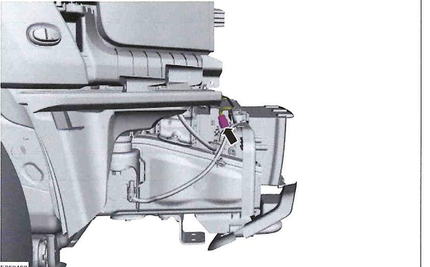
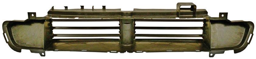
Ford F-150 upper shutter assembly. Note wiring harness. (courtesy Mitchell 1)
Demanding applications require the most reliable


powerful battery. Super Start® batteries provide optimized power solutions to handle even the toughest environments. Super Start® makes thousands of different sizes and types of lead-acid and AGM batteries, battery accessories, and wire and cable products for virtually any application.


JUNE 2023 | ASP 17 FIRSTCALLONLINE.COM Visit our website for a complete, internet-based catalog designed exclusively for the Professional. NATIONWIDE WARRANTY ASSISTANCE
a Super Start ® battery fails and the vehicle is over 25 miles from your shop, the customer will be directed to the closest repair facility. They suffer no expense for warrantable repairs.
If
AUTOMOTIVE AND SPECIALTY BATTERIES
• Agricultural • Automotive • Commercial • Emergency lighting • Fleet and heavy-duty • Golf cart • Lawn and garden • Marine • Military • Motorcycle • Off-highway • OTR trucks • Powersports • Personal mobility SUPER START® BATTERY B O N U S ! Earn account credit on qualifying Super Start ® Battery purchases. See store for details. AU TOMOT AVAILABLE EXCLUSIVELY AT View our complete catalog by scanning this code with your smart phone camera. Let Us Be Your Parts & Equipment Supplier BATTERIES & ACCESSORIES A COMPLETE LINE OF FROM SUPER START® ADV 1843 REWARDS FOR PURCHASING & INSTALLING THE BRANDS YOU KNOW & TRUST FOR DETAILS VISIT FIRSTCALLONLINE.COM nationwide warranty ROADSIDE ASSISTANCE
and
Dorman and SMP) notes that there are a number of issues that can cause an AGS system to fail or work improperly. Some of the most common causes include physical obstructions, excessive debris or electrical issues such as a failed actuator. An actuator with a short in the actuator harness or a connector that is broken, bent, pushed out or has significant corrosion can cause problems in AGS function. Finally, collision damage can cause an AGS system to work improperly or stop working altogether. Any of these issues can cause more severe problems with a vehicle, including overheating the engine due to the restriction in airflow. With the ever-growing number of trucks and SUVs that utilize AGS systems, it is crucial that service providers understand some of the common problems associated with them.
An array of sensors/signals work in unison to provide the ECM with the required operation. In addition to the engine coolant temperature sensor and vehicle speed monitoring, air speed sensors may be located in the front of the vehicle to measure airflow volume and direction. If the AGS system detects a problem, the
check engine light will illuminate. If the system begins to act erratically (constant opening/closing), or remains stuck in the closed position, this can potentially result in engine hot spots (overheating) due to uneven or insufficient airflow. While AGS in theory is a good idea, as it is intended to speed initial engine warm-up, decrease emissions and reduce parasitic drag, the presence of the shutter system in front of the radiator poses the potential of blocking airflow through the radiator if the shutters become stuck in the closed position. As with many technological advancements, there are pros and cons. AGS is an example of one more variable thrown into the equation. Note that a problem with AGS may or may not illuminate a MIL indication to the driver.
As noted earlier, AGS is featured on a range of vehicle makes/models. Examples include, but are not limited to, 2017 and later Honda CRV and Odyssey, 2013 and later Dodge Ram, 2012 and later Ford Focus, 2016 and later F-150, various GM vehicles from 2012 and later, 2016 and later Toyota Prius, 2022 and later Tundra, 2019 and later RAV4, 2022 and later Titan. Again, this is merely a sampling of makes/models that feature AGS.
VARIABLES BY VEHICLES
Here’s a look at how it works in some makes and models.
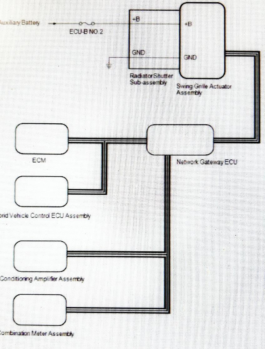
2020 Toyota RAV4 Hybrid: The swing grille actuator assembly receives signals from the ECM, hybrid vehicle control ECU assembly and air conditioning amplifier assembly via CAN communication. Based on these signals, the swing grille actuator assembly operates the radiator shutter sub-assembly. If a malfunction occurs, a warning will be displayed and grille shutter system operation will be disabled.
The grille shutter closes or opens when certain conditions related to the vehicle speed, engine coolant
18 ASP | JUNE 2023 ACTIVE GRILLE SHUTTERS
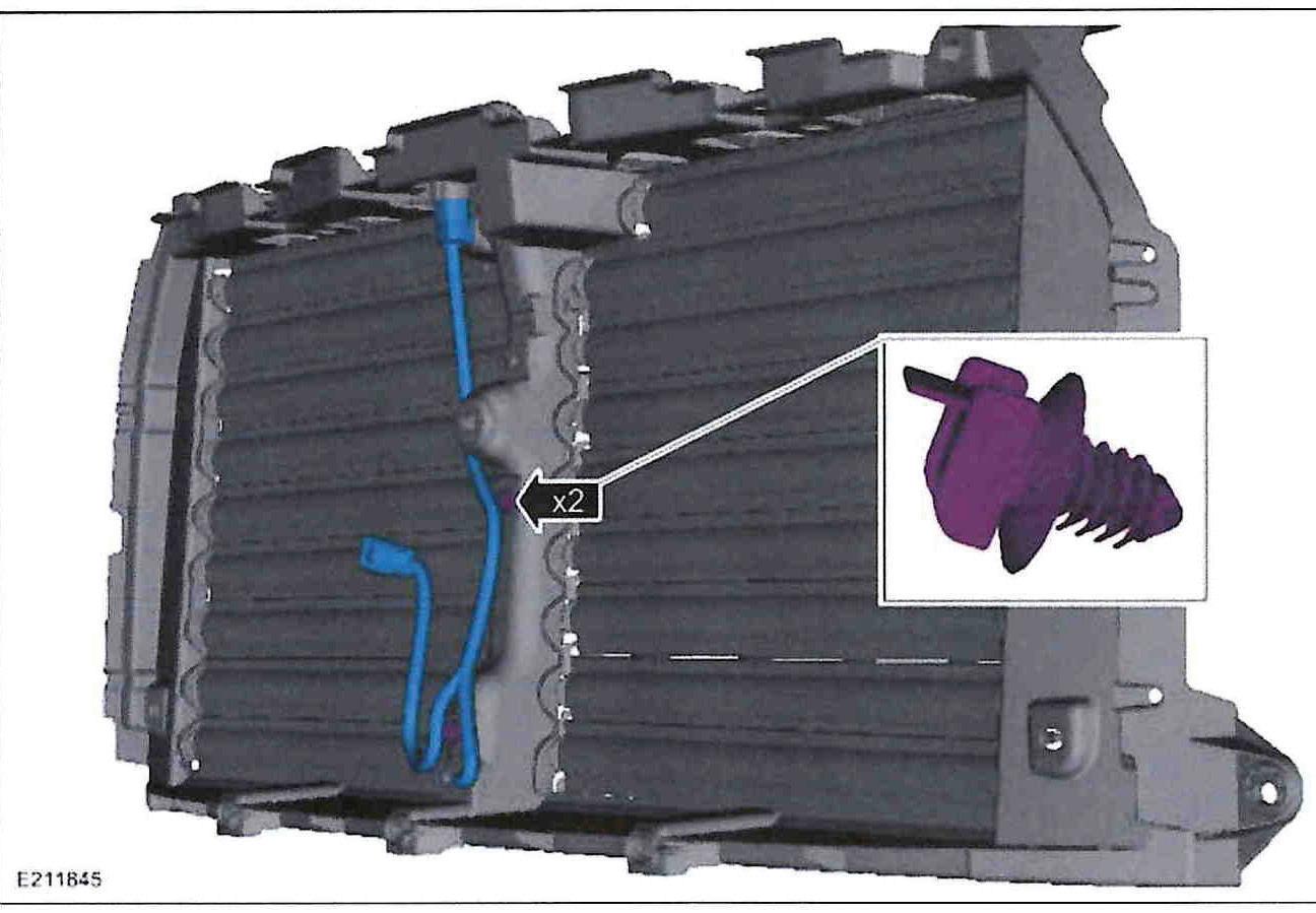
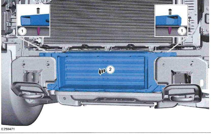
Ford F-150 lower shutter assembly (courtesy Mitchell 1)
Ford F-150 lower shutter wiring harness. (courtesy Mitchell 1)
Ford F-150 ABS module provides vehicle speed information to the PCM as part of the position command for the shutter(s). (courtesy Mitchell 1)
temperature, inverter coolant temperature, ambient temperature and refrigerant pressure are met. When the ignition switch is shut off, the grille shutter opens to prevent the grille shutter from becoming stuck closed while the vehicle is stopped. Trouble areas may include the swing grille actuator assembly branch wire or connector, the power source circuit of the swing grille actuator assembly, swing grille actuator assembly ground circuit, the swing grille actuator or radiator shutter assembly.
The Toyota system, citing but one example, is designed to open the shutter system when the engine coolant temperature reaches 167 F. At vehicle speeds of 37-93 mph, the shutter closes. The shutter opens automatically when air temperature reaches 95 F or higher and/or when engine temperature reaches about 204 F. During cold winter operation with ambient temperature of 41 F or lower, the winter control mode function suspends grille operation in other than fully open or fully closed to prevent grille freeze-up.
Using Toyota RAV4 Hybrid AGS as an example, these are potential trouble codes:
• B1333: Shutter control state maintenance mode,
• P059F-73: Active grille air shutter “A” actuator stuck closed,
• P05A0-72: Active grille air shutter “A” actuator stuck open,
• P05A0-74: Active grille air shutter “A” actuator slipping,
• P05A2-11: Active grille air shutter “A” circuit short to ground,
• P05A2-12: Active grille air shutter “A” circuit short to battery,
• P05A2-13: Active grille air shutter “A” circuit open,
• P05A2-7E: Active grille air shutter “A” actuator stuck on,
• P05A2-7F: Active grille air shutter “A” actuator stuck off,
• P05B1-12: Active grille air shutter “B” circuit short to battery,
• P05B1-14: Active grille air shutter “B” circuit short to ground or open,

• P05B1-31: Active grille air shutter “B” no signal,
• U1293-87: Lost communication between hybrid powertrain control module and active grille air shutter...missing message.
Note that regardless of make/model, P059F is the “generic” code that indicates an AGS problem, usually indicating a stuck-closed shutter issue.
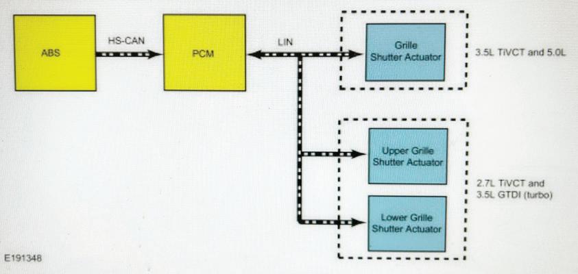
2016 and later Ford F-150: The active grille shutter system is primarily used to maximize fuel economy by reducing aerodynamic drag, and to shorten engine warm-up time. The active grille shutter actuator(s) receive position commands from the PCM. The active shutter system carries out a calibration sequence whenever the engine is started, fully opening and closing the shutters before positioning the louvers in the programmed position as requested by the PCM. If the truck is equipped with a 2.7L or 3.5L GTDI turbo engine, there are two independent shutters. The upper active grille shutter system is controlled in the traditional sense, which is to moderate air flow to the underhood area. The lower active grille shutter system is dedicated to thermal management of the turbocharger CAC (charge air cooler).
As mentioned, the active grille shutter actuator positions the shutters based on commands from the
JUNE 2023 | ASP 19
Example of shutter pivoting system. (courtesy Dorman)
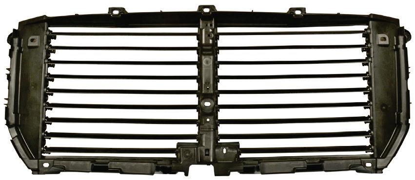
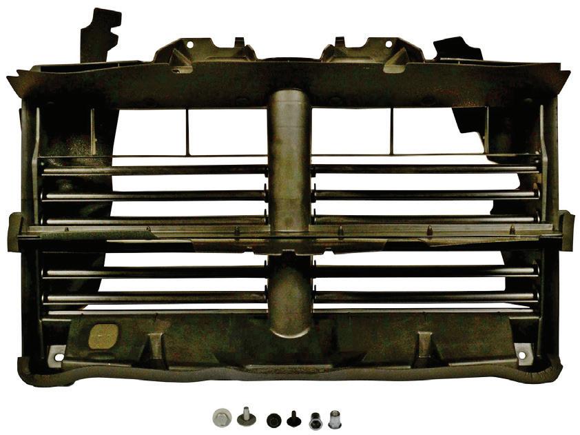
Example of active shutter for 2015-2017 Ford F-150. (courtesy SMP)
2015-2017 Ford F-150. (courtesy SMP)
PCM. The shutter moves 90 degrees from fully closed to fully opened, and based on the position commanded by the PCM is set in one of 16 positions (with about 6 degrees between positions). During normal operation, the shutters may be partially to fully open when the engine is off, depending on ambient temperature. Once the engine is started, a self-calibration occurs which takes about 15 to 20 seconds. The active grille shutter system performs the calibration sequence by detecting the open and closed positions, and continues until successful or a fault is detected. If faults are found (shutter blocked or actuator error), a recalibration is initiated. If the problem is not resolved after three or four attempts, a timer starts and sets a DTC when the timer reaches a predetermined limit.
In a system that features both upper and lower shutter assemblies, the upper shutter control is based on various PCM inputs including vehicle speed, coolant temperature, ambient temperature and A/C system pressure). If equipped with turbochargers, the lower shutter assembly control is dedicated to managing charge air temperature into the turbochargers and is based on additional inputs including turbo charge pressure and charge air temperature.
The PCM communicates with the AGS via a LIN. The LIN supports bi-directional communication between the AGS and the PCM, allowing the AGS
actuator(s) to communicate position and fault information to the PCM. The PCM sets AGS DTCs when fault information is communicated by the AGS for a predetermined amount of time. Any failures of the LIN for over 10 seconds continuously results in the AGS actuator positioning the grille shutter fully open. There is no indication to the driver when a fault with the AGS is present or an active AGS DTC is set in the PCM.
The AGS actuator is a smart motor which receives position requests from the PCM via the LIN. One of the active grille shutter blinds connects to the AGS shutter actuator using a retainer. The actuator can be serviced separately or as an entire assembly (which includes the active grille shutter, actuator, retainer, housing and jumper harness). The shutter is comprised of shutter “blinds” which are linked together. One of the blinds is fixed to the actuator. When the actuator moves, it moves the attached shutter blind, which causes the remaining blinds to move.
GM vehicles: A shutter performance issue will always present DTC P059F (active grille air shutter 1 performance) and possibly U0284 (lost communication with actuator 1) for the upper shutters and P05AE (active grille air shutter 2 performance) and U0285 (lost communication with active grille air shutter actuator 2) for the lower shutters. According to GM, shutters should never be replaced if these DTCs are not present.
Check for U0284 and U0285. On light duty trucks, these codes may be paired with DTC U0632 (lost communication with cooling fan motor), U0633 (lost communication with engine cooling fan 2), U0180 (lost communication with battery monitor module) or U1345 (engine control module LIN Bus 1). If any of these codes are set, check the condition of the aero shutter fuse, engine wiring harness, jumper harness to the shutter actuators, X133 connector and other connectors to the
20 ASP | JUNE 2023 ACTIVE GRILLE SHUTTERS
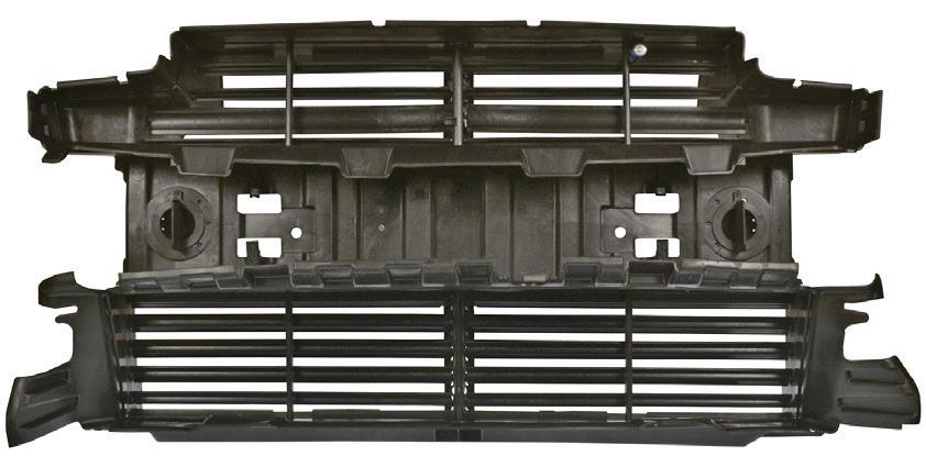
2013-2016 Ford Escape. Note the integrated upper and lower shutters. (courtesy SMP)
2014-2017 Jeep Cherokee. (courtesy SMP)
2013-2017 Ram 1500. (courtesy SMP)


aero shutter and J170 splice (light duty trucks only). Even a small amount of movement of the splice may cause an intermittent communication issue.
If DTC P059F and P05AE are set, check for debris in the upper and lower shutters (a louver/vane that may be disengaged from the linkage or a shutter that is binding). Try to remove any debris by hand or by using compressed air before potentially wasting time removing the front fascia and shutter.
On light duty trucks, the upper shutter may be binding in the left side air induction plenum. On both light trucks and SUVs, also check for shutter binding on the right side horn or bracket. You should have at least 10mm of clearance between the shutter louver and horn.
MULTIPLE AGS ON ONE VEHICLE
Some vehicles have more than one Active Grille Shutter that can fail or operate improperly. Vehicles can have an upper, lower, left, and right AGS and if that causes a DTC, it is important for technicians to determine which shutter is the culprit.
MAINTENANCE

It should come as no surprise that, due to the nature of having a series of shutters pivoting up and down as temperatures and vehicle operation change, the shutters must be able to operate freely upon command. While it’s always been important to keep the radiator area clean and free of debris, when a vehicle features AGS, cleanliness becomes even more important. Whenever the vehicle is in your shop for service, try to remember to inspect the AGS and to remove any debris that may cause interference, such as leaves, dirt, insects, etc. If winter conditions result in ice/snow accumulated in the louvres, spray the louvres with warm water or with the careful use of a heat gun to clear any obstructions.
If AGS operation is a concern, inspect the seals/gaskets around the shutter. Damaged seals can allow moisture and dirt to accumulate. If a thorough cleaning is needed, remove the shutter assembly from the vehicle and clean with hot water and soap (such as dishwashing liquid), and then lube the shutter pivot points with a light lube such as WD-40. Reinstall and test the shutter by starting the engine and allowing it to reach operating temperature, noting shutter movement.
Also inspect the shutter assembly to verify that all shutters are straight and parallel with each other. Depending on design, you may be able to correct shutter panel misalignment by loosening the screws that secure the louvers to the frame, aligning and retightening the screws.
Checking an existing AGS or verifying a replacement AGS for operation is easily done with your scan tool by commanding the shutters closed and open. If replacing the AGS, performing commanded tests allows you to verify operation before you go to the trouble of reinstalling the grille and other surround components.
22 ASP | JUNE 2023 ACTIVE GRILLE SHUTTERS
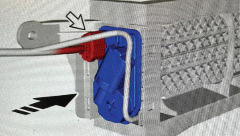
Example of Toyota AGS electrical connector. (courtesy Mitchell 1)
Example of Toyota AGS circuit. (courtesy Mitchell 1)
FIND. ORDER. DELIVERED. YOUR TIME MATTERS LESS TIME CLICKING. MORE TIME FOR FIXING. MYPLACE4PARTS is the easiest, fastest parts ordering platform for professional technicians. www.myplace4parts.com
Testing 3-Phase High Voltage Electric Motors
Conduct four stator checks in 30 minutes
 BY CRAIG VAN BATENBURG
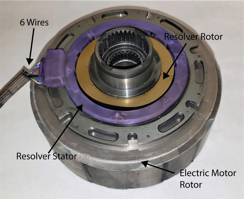
THERE ARE TWO PRIMARY PARTS IN an HV electric motor. The “rotor” that rotates and provides power, and the “stator” that produces a threephase rotating electromagnetic field.
The stator consists of electromagnets arranged in a circle. Three HV cables (or bars) attached to the stator provide power to the stator from the inverter. The inverter gets its power from the HV capacitors, and they get their power from the high-voltage battery pack.
What motor types are used in EMVs today? Modern electric drive vehicles (since M/Y 2000 nationwide) in North America use one of two types of motors:
1. Three phase alternating current (AC) brushless interior (or exterior) permanent magnet (PM) synchronous motor (98 % of all EMVs)
2. Three phase alternating current (AC) brushless induction asynchronous motor (Some Teslas and GM)
24 ASP | JUNE 2023 ELECTRIC MOTORS
Induction motor. (all photos courtesy ACDC)
ROTOR
In a PM motor, the rotor is usually held by bearings at each end of the shaft that the rotor rotates on. In the case of the old IMA (Integrated Motor Assist) Honda system, it is mounted on the end of the crankshaft. The PMs are attached to the rotor in such a way that there is a North magnet(s), then a South magnet(s) and then more of the same. Surrounding the inner (or outer) rotor are many permanently mounted electromagnets. The polarity of the electromagnetic fields (the stator) is switched rapidly by the inverter.
BEARINGS
One problem that can come up with these types of motors is rotor bearing failure. That can happen when the rotor shaft creates its own current that flows through the rotor bearing at one end and then back to the rotor shaft using the other bearing. Before long the bearings — having lost some metal on the face of the rotating bearing — fail, as the metal is eaten away. To keep that from happening, there are two solutions. One being to add brushes to the rotor shaft to “ground” the electrical charge, or insulate one of the bearing’s inner or outer races to create an open circuit.
STATOR
The part of the motor that does not move is the stator. If you look at most stators you will see slotted cores made of thin sections of steel, wound with insulated copper wire to form one magnetic pole. Then, that same wire is moved opposite that pole to make one more pole 180 degrees away from the original one. There are three windings in each motor that are 120 degrees apart and are labeled U – V - W.
RESOLVER
When Toyota designed their transmission, with the help of Aisin Corp., resolvers were required to report the position of the rotor before it was rotated. That was a new type of sensor. More to learn here in the future.
DIAGNOSTICS FOR ELECTRIC AC MOTORS
The inverter powers the AC motors on EMVs. Each motor/generator (M/G) has its own inverter. Think of an inverter as a “motor controller.” If the motor cannot work as a generator, then it is just a motor, like an air conditioning compressor. AC motors do not use brushes
like some DC motors. Having no brushes means less maintenance and cost. Also, RPM is easier to control on an AC motor, simply because the frequency applied is easier to control. Less frequency, less speed. If the motor is a permanent magnet motor — either an interior or exterior magnet design — the possibility of a magnet breaking into pieces is next to zero, so cross that off your list. The probability of a magnet losing its strength is extremely low and if it did, it would take a very high temperature to demagnetize these strong magnets. The heat required would most certainly melt coil winding
26 ASP | JUNE 2023
ELECTRIC MOTORS
Resolver used for reporting the speed, position and direction of the rotor.
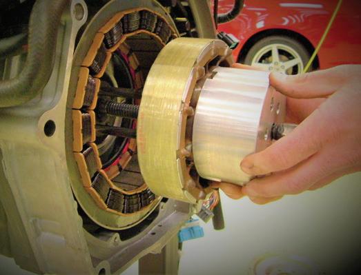
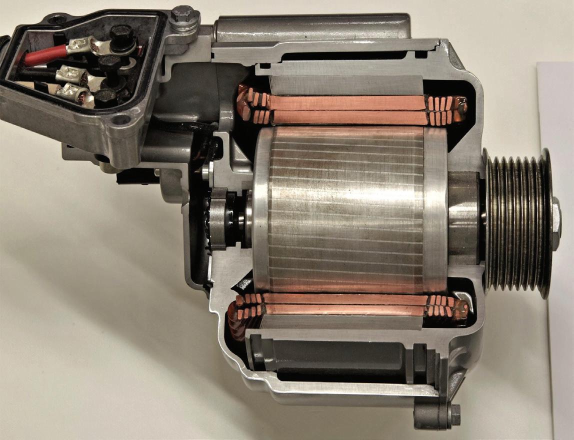
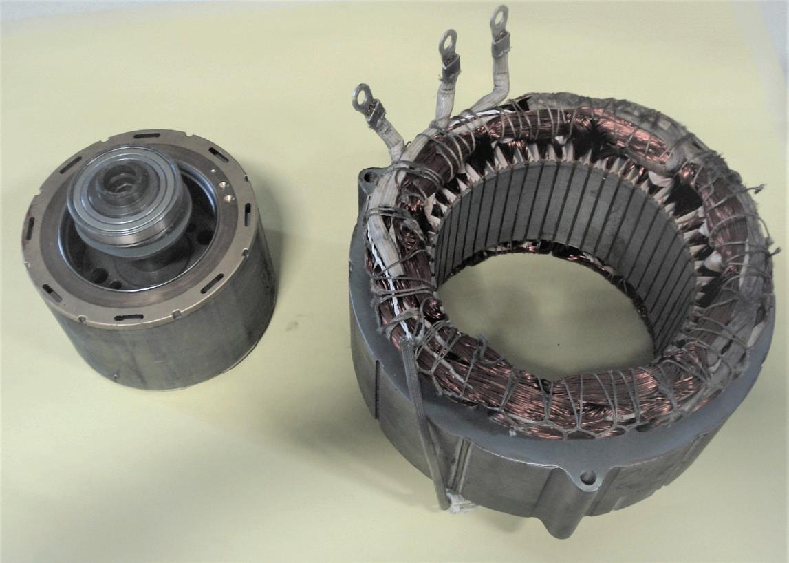
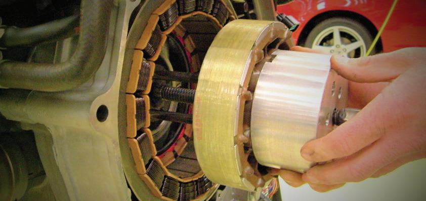
Rotor on the left. Stator on the right.
insulation, plastic connectors and such. What about the bearings that support the rotor? That possibility is low, but it could happen. A dial indicator would be an appropriate tool there. If you are testing an induction motor (early Tesla and GM eAssist for example), the rotor has no magnets. It also rarely fails. The only thing that may happen is the rotor would scrape the stator if the support bearings failed. This would produce aluminum and copper dust. In turn, that would short the AC to the chassis and the system would set a fault code for a HV leak. Game over.

That leaves the stator as a suspect. The stator can be damaged with heat, poor construction, attacked by acids in old transmission fluid (the stator is often cooled that way), magnetic vibration issues, and loose connections (more heat). The stator is not visible without a lot of disassembly in most cases, so how do we test for a problem there? If it is a PM motor and you can figure out a way to rotate the rotor. It can be easy.
FOUR OPTIONS TO TEST THE STATOR


Test 1. Make a three-bulb tester. You will need three old fashioned filament bulbs (for example, No. 1587). Using the bulb socket holder, attach two alligator clips to each wire so you have three light bulbs that are the same. Once the three-phase cables have been removed from the inverter, connect the bulbs to the three cables and rotate the rotor. The bulbs should all light up and be the same intensity. If one is dim, verify that the connections are good by changing the positions of the bulbs. A dim bulb indicates low output on one phase.
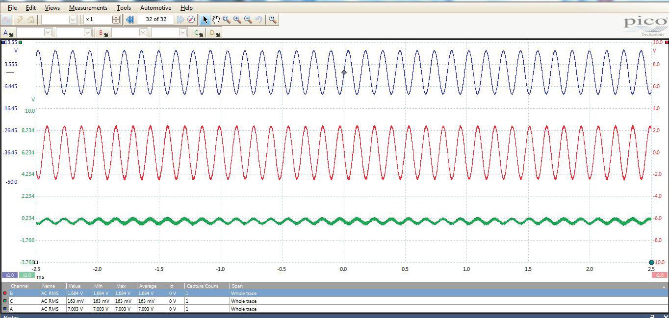
Test 2. While the bulbs are attached to the inverter, connect a lab scope to the orange cables and watch the amplitude. The bulbs will still light up, but now you can see a wave form. The three phases should all look the same.
Test 3. Using a milliohm meter, make the same connections to the three-phase cables. You may need to look up a specifi-

JUNE 2023 | ASP 27 DOES NOT contain PaintBlock® Technology Prep for Perfection. ® Visit FrogTape.com/Performance FROGTAPE ® PERFORMANCE MASKING TAPES Engineered for challenging marine, automotive, transportation and other applications where industrial coatings are applied. The only thing they won’t mask is your craftsmanship. ©Shurtape Technologies, LLC 2023/ASW00505 2306ASP_ShurTapeTech.indd 1 4/27/23 8:52 AM
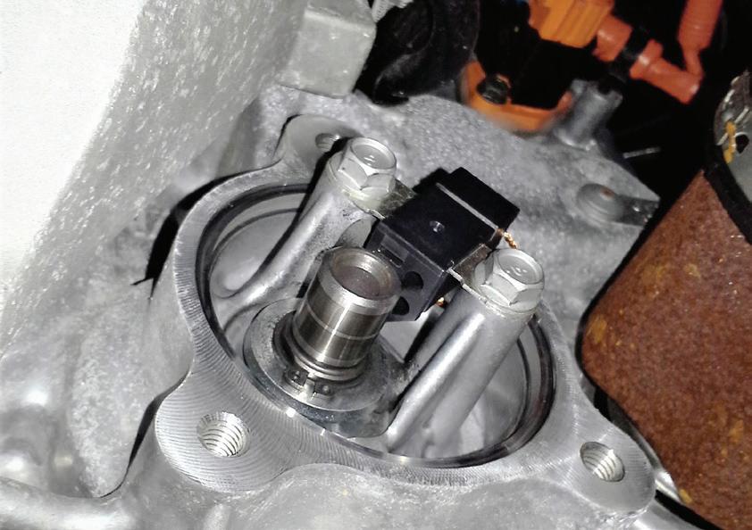
Rotor being removed from a Honda IMA system.
Known good resolver wave form.
cation if the test shows an out-of-balance stator phase. Make sure the three phases are all equal in ohms. This test will help discover shorted stator windings that short to each other in the same phase, short to ground, short to the temperature sensor (if it has one), or shorts to another phase. If the test shows a failure, take the motor apart enough to remove the orange cables from the system and test again at the stator itself. It is possible to have a high resistance connection or bad orange cable and the stator may be OK.
Test 4. This test will make use of your insulation tester. You are now adding high voltage (with very low current) to the stator and attaching the meter’s ground lead to the stator’s case. You are looking for an isolation issue that will show you bad insulation on the coil windings of the stator.
TESTING AND REPLACEMENT
The four tests can all be done in under 30 minutes once you know your equipment and have access to the orange cables that feed the AC to the stator. There are two tests for induction motors, tests 3 and 4. When there are no magnets, tests 1 and 2 will not work. Once you have determined the stator is defective, it must be replaced.
Nissan Leaf uses a set of brushes to ground to the rotor shaft. There are companies that can rewind a stator, but typically it is replaced with a new one. Some OEMs have designed this for easy removal (or the technician is just lucky) and other OEMs will have you replace the entire assembly.
Craig Van Batenburg is the lead trainer and CEO of ACDC, a hybrid and plugin technician training company based in Worcester, Mass. ACDC started hybrid training in early 2000. ACDC owns a fleet of 16 EMVs, from the most popular models to current EVs. Recently, ACDC has expanded to 5,000 square feet and added a battery lab. Class info is available at www.FIXEV.com or call 508 826 4546. Contact Craig at Craig@fixhybrid.com.
28 ASP | JUNE 2023 ELECTRIC MOTORS
Chrysler Diagnostics
Scan tool unlocks robust data and tests
BY BILL FULTON
SCAN DATA DIAGNOSTICS BEGAN ON the GM systems in the early ‘80s. The Chrysler models began giving us scan tool data and functions in the mid‘80s. In comparison I have always felt the Chrysler system proved to be very robust.


The Chrysler computer system began with a twowire system known as CCD. The DLC connector uses two circuits to communicate with the scan tool known as Receive and Transmit for PCM and TCM data. The point here is that there will be no communication with the scan tool until a request is made by the scan tool. The Receive and Transmit circuits are dedicated to engine and transmission data only. On the early CCD systems, the other modules communicated on the CCD+ and CCD- circuits. In the early ‘90s the CCD systems were being phased out and a single wire PCI circuit was introduced. The PCI buss circuit reports data to pin 2 of the DLC. The same rule applies in that the PCM and the TCM will communicate on a two-wire Transmit and Receive circuit. The same rule applies in that a re -
JUNE 2023 | ASP 29 CHRYSLER DIAGNOSTICS
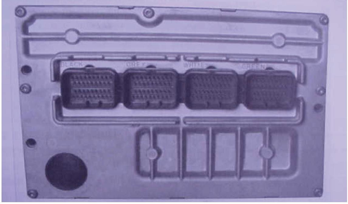
Fig 1: The Huntsville controller can be identified by its cooling fins.
Fig 2: The Chrysler server must be enlisted by the scan tool before access to the entrance side of the PCM.
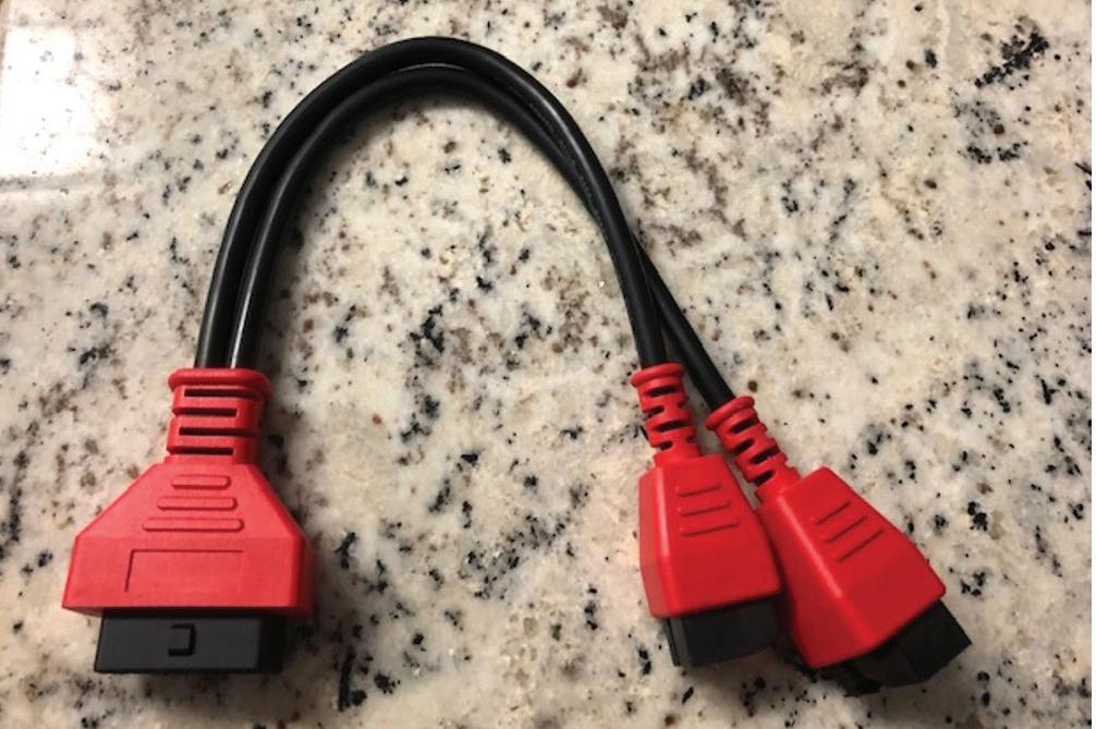
Fig 3: Using a Y adapter cable that interfaces the scan tool to the security gateway module is not a good idea.
quest must be made by the scan tool before the PCM or the TCM sends data. The single wire PCI bus is used on all the other modules. When Chrysler went fully CAN compliant in 2008 the PCM and the TCM communicated on a two-wire CAN High & CAN Low circuit.
Pin 6 of the DLC is known as CAN High while pin 14 is known as CAN Low. On Chrysler CAN compliant systems there is no activity on the bus circuit until a scan tool is connected and a request is made.

Though the bus circuits have changed since the mid-‘80s, the scan tool data and functions have been uniform and more robust as the years changed. The framework of this article will cover the data and functional tests from the PCM platform. We will focus on the modern-day systems whereas Chrysler introduced a new PCM known as NGC or Next Generation Controller. There are two versions, one being the Huntsville Controller, and the second being the Motorola controller. The Huntsville controller can be identified by its cooling fins. See Fig.1. These controllers

are not interchangeable, nor can they be flashed from another VIN vehicle. However, one aftermarket scan tool company has found a way to write a new VIN to a salvage yard PCM. The results of this vary from a successful process to a failure so it is not reliable to pursue this strategy.
Access to the bus circuits has undergone a major change from the folks at Chrysler beginning in MY 2018. Access on the global side of the scan tool is easy and automatic. However, due to the considerable number of cyberattacks on these vehicles, Chrysler has enlisted a server that the user of a scan tool must connect

30 ASP | JUNE 2023
CHRYSLER DIAGNOSTICS
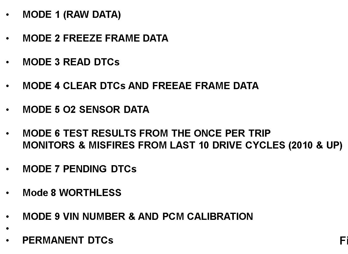
Fig 4: Example of the 10 modes for data access.
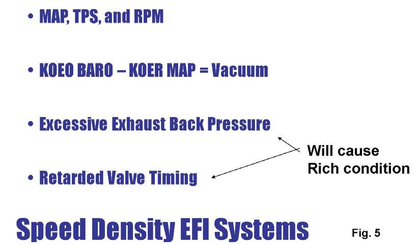
Fig 5: Any problem that reduces manifold vacuum will shift the MAP voltage high, resulting in a rich condition and retarded timing.
Fig 6: Example of an aftermarket scan tool test while conducting a network check.
Fig 7: Chrysler Wi-TECH PC based scan tool network test. Modules in blue indicate module is online and no DTCs. Modules in yellow are online but have DTCs.
2-PIECE POCKET

PRY BAR SET
Convenient for prying and separating small items apart
3/16" diameter steel with high fatigue and torsional strength


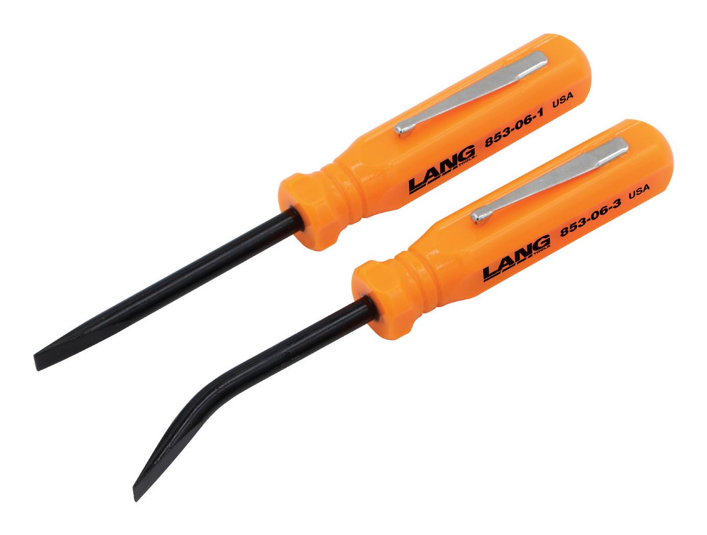
Angled blade gives greater access to tight areas

Set contains straight and 27¡ offset pry bars


OVERALL LENGTH OF FIVE INCHES


JUNE 2023 | ASP 31 WWW.LANGTOOLS.COM
2306ASP_A&EHandTools.indd 1 5/9/23 10:26 AM
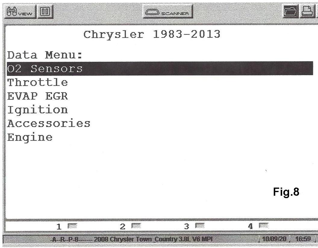
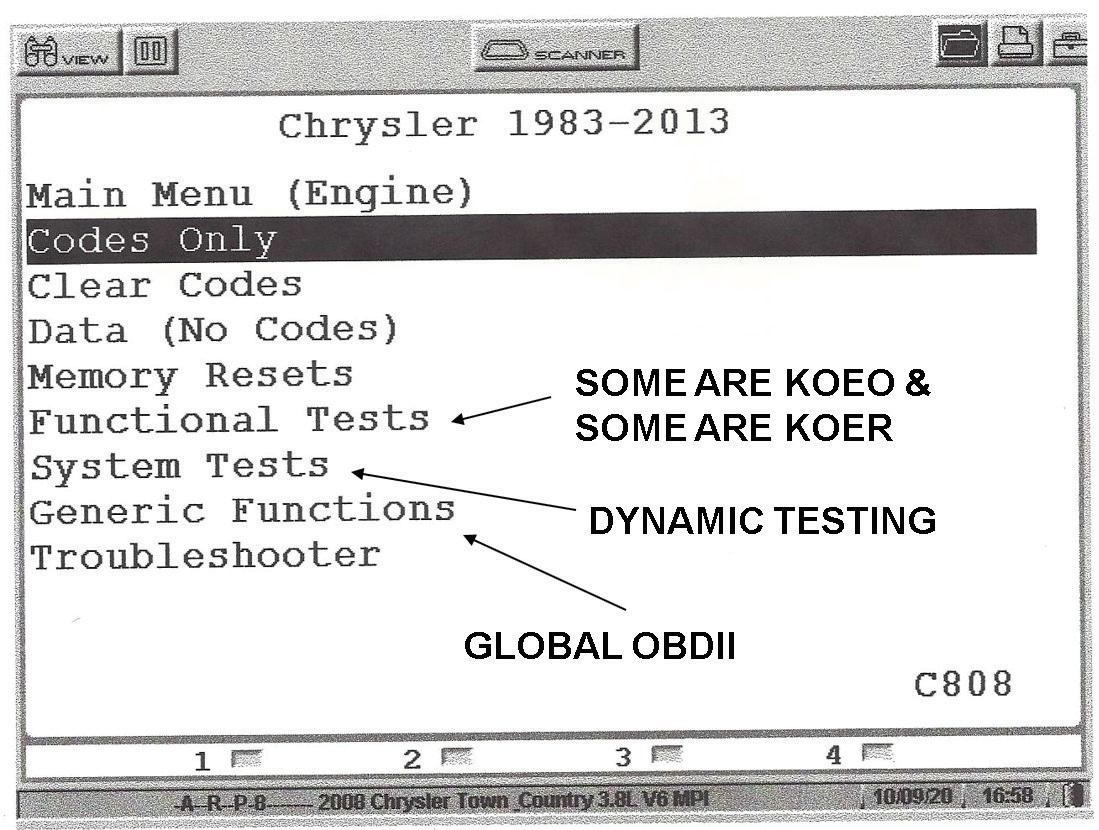
Fig 8: Example of the main menu on Chrysler scan data. Fig 9: Example of selecting data from an individual data pack with an aftermarket scan tool.
CHRYSLER DIAGNOSTICS
to before accessing the enhance side of the PCM with the scan tool. See Fig. 2 The reason for this: should a cyberattack occur and the vehicle is stolen, the website would have a record of who accessed the theft deterrent system. Put simply, you will need to be online with your scan tool to access the enhanced side of the scan tool. There is another option that is not a good choice which involves buying a Y adapter cable that interfaces the scan tool to the security gateway module. See Fig. 3. The problem here is that access to the security gateway module is very difficult. Most of these modules are located deep inside the dash behind the radio or HVAC control panel. Whenever accessing the bus circuits on Chrysler systems, Chrysler uses its same old strategy in that there will be no activity on the bus circuits unless a scan tool is plugged in and a request is made.
I would like to remind our readers that the global side of the scan tool yields a tremendous amount of data that I feel should be initially accessed in the event of a MIL. The 10 modes are shown in Fig. 4. We wrote an article previously in Automotive Service Professional covering in detail the importance of the 10 modes available on the global side of the scan tool.
The framework of this article will focus on the data and functions available on the enhanced side of the scan tool on the CAN compliant Chrysler systems. First and foremost, we need to remind ourselves that Chrysler still uses the Speed Density type fuel and spark control strategy by using the MAP sensor as a major input for fuel control and spark timing. Any problem that reduces manifold vacuum will shift the
32 ASP | JUNE 2023
Fig 11: The ignition data packet is selected. Notice the cam and crank sensor PIDs indicating in sync.
Fig 10: Using an aftermarket scan tool, these are some of the choices available on the tool’s enhanced side when selecting an individual module.
Fig 12: When looking at PIDs dynamically in graphing mode, notice that the sync state and cam variance will not be stable as RPM changes.
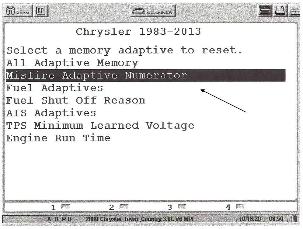
Fig 13: Here’s a list of adaptive resets, with the misfire adaptive numerator highlighted.
MAP voltage high which caused a rich condition and retards the spark timing. See Fig. 5.
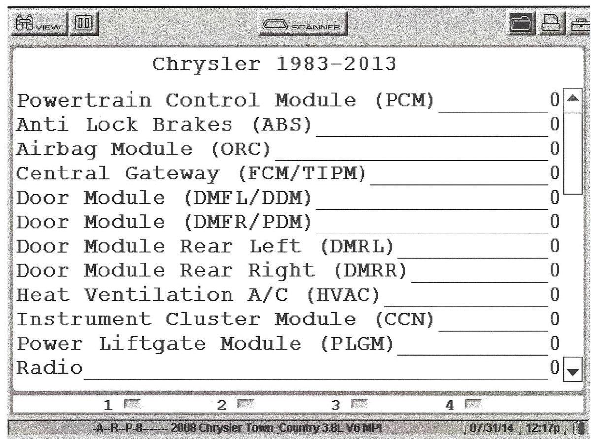
Most of us technicians know the importance of doing a network test initially on these modern-day vehicles. The network test involves checking to see if a module is online and communicating and whether or not the module has a DTC. An aftermarket scan tool test is indicated in Fig. 6 while conducting a network check. If the PCM is not listed it means there is no communication with that module. Notice in this example that no module indicated a DTC. The Chrysler Wi-Tech PC based scan tool indicates the network test is shown in Fig. 7. The modules that are colored blue show that the module is online, communicating and there are no DTCs. The modules that are colored yellow signify the modules are online but have DTCs.


JUNE 2023 | ASP 33 Technology driven Built on our pioneering technology and OE expertise, our full-service aftermarket fuel solution offers premium parts, leading vehicle coverage, training and technical support, to help ensure vehicles drive cleaner, better and further right through their lives. delphiaftermarket.com Delphi Technologies is a brand of BorgWarner Inc. Learn about our fuel tank cleaning tool 2306ASP_DelphiTech.indd 1 5/1/23 12:58 PM
Fig 14: Follow the manual reset procedures if the MIL remains on or ABS light remains on.
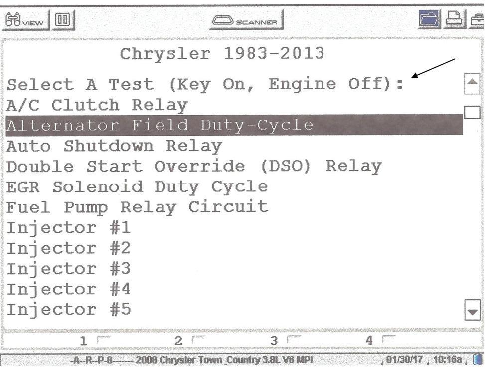
Fig 15: List of KOEO tests available under the functional test menu.
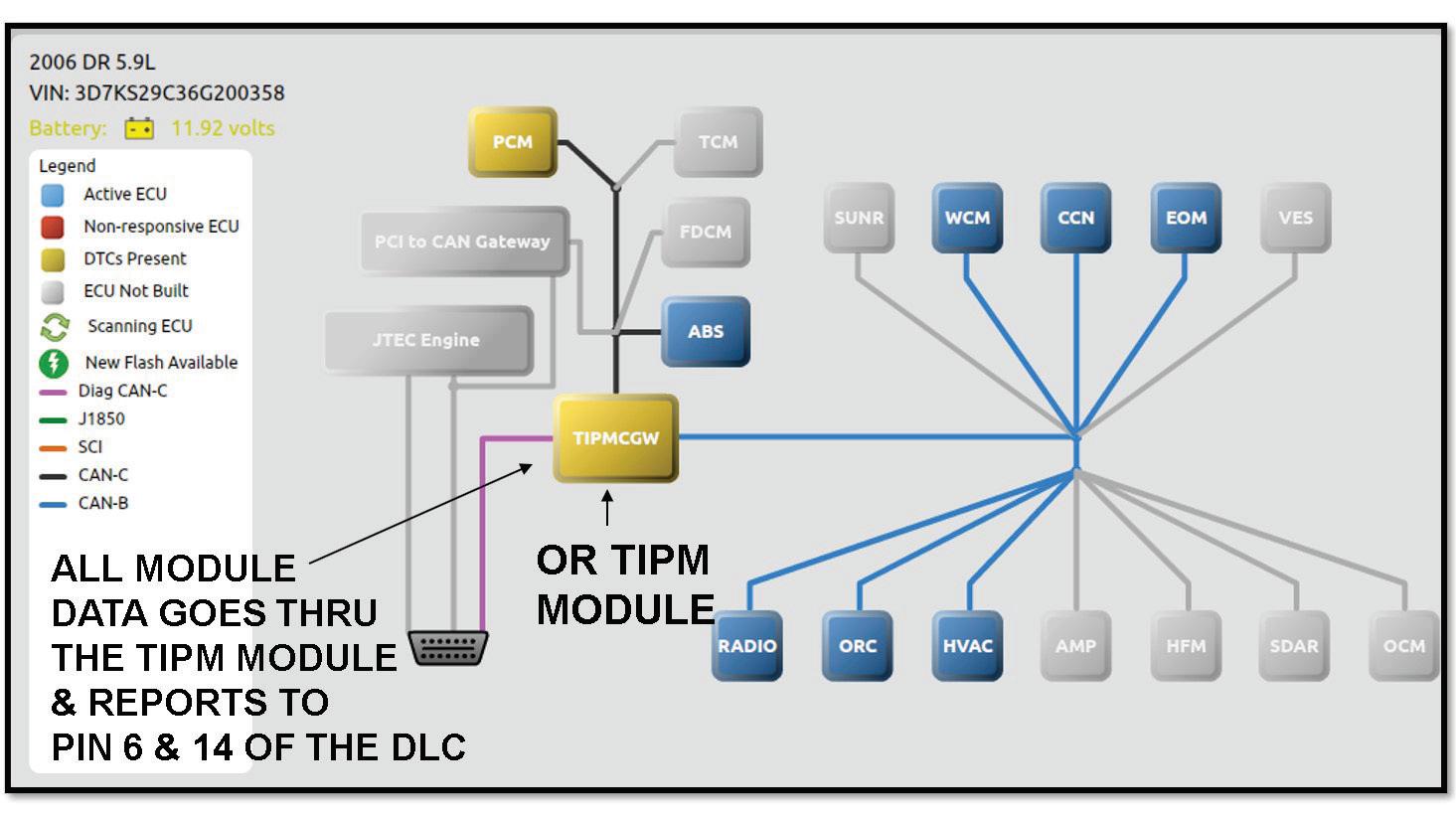
In a later article we will pay a lot of attention to the TIPM module which is the dominant module in the bus circuit. This module is known as the bus master, meaning all scan data from all modules must go through the TIPM module. This module also powers up nearly every component on the Chrysler CAN-compliant systems.
When considering whether a Chrysler vehicle is CAN-compliant, keep in mind the Chrysler minivans were the last Chrysler vehicles to become CAN complaint in MY 2008. The main menu on Chrysler scan data is shown in Fig. 8. It’s important to learn the differences between the functional test menu and the system menu. Fig. 9 is an example where we select data from an individual data packet when using an aftermarket scan tool. This is important in that it streamlines the data and improves the scan tool update rate. For example, if an air fuel ratio problem exists it would be wise to select the O2 data packet.
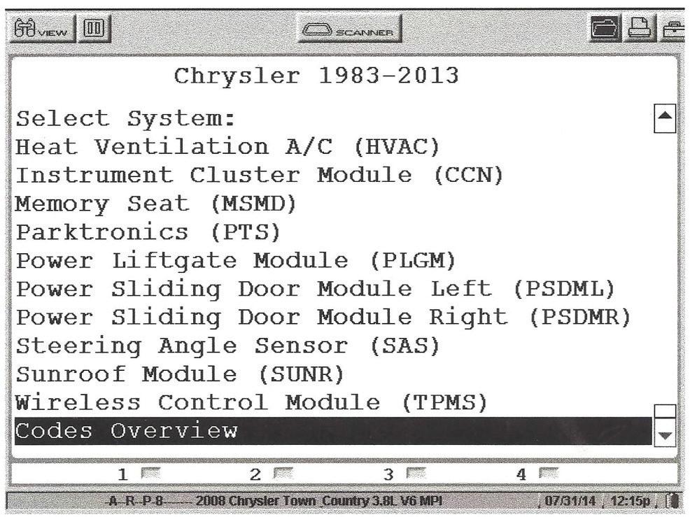
There are major differences between aftermarket scan tools as to how their menus are displayed. Fig. 10 from an aftermarket scan tool indicates the choices available on the enhanced side of the scan tool when selecting an individual module.
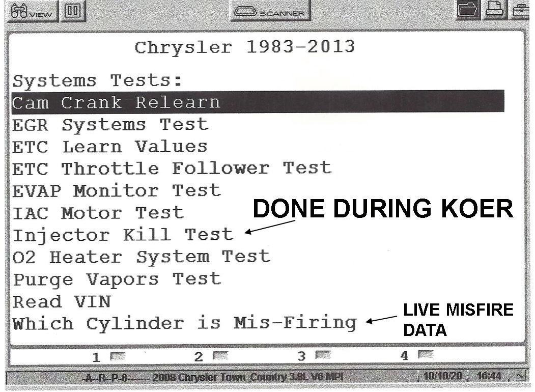
When selecting the system test menu you will see choices such as live cylinder misfire tracking, the EVAP monitor, testing the Electronic Throttle Control
34 ASP | JUNE 2023 CHRYSLER DIAGNOSTICS
Fig 16: List of KOEO tests available under the functional test menu.
Fig 17: These options are listed on the system test menu.
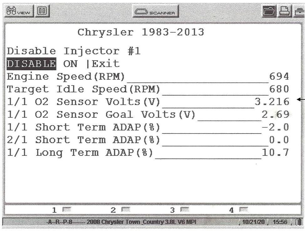
Fig 18: Notice the oxygen voltage before an injector was disabled.
Fig 19: Here’s the lean shift when an injector was disabled.


JUNE 2023 | ASP 35 2306ASP_PowerProbe.indd 1 5/8/23 2:31 PM
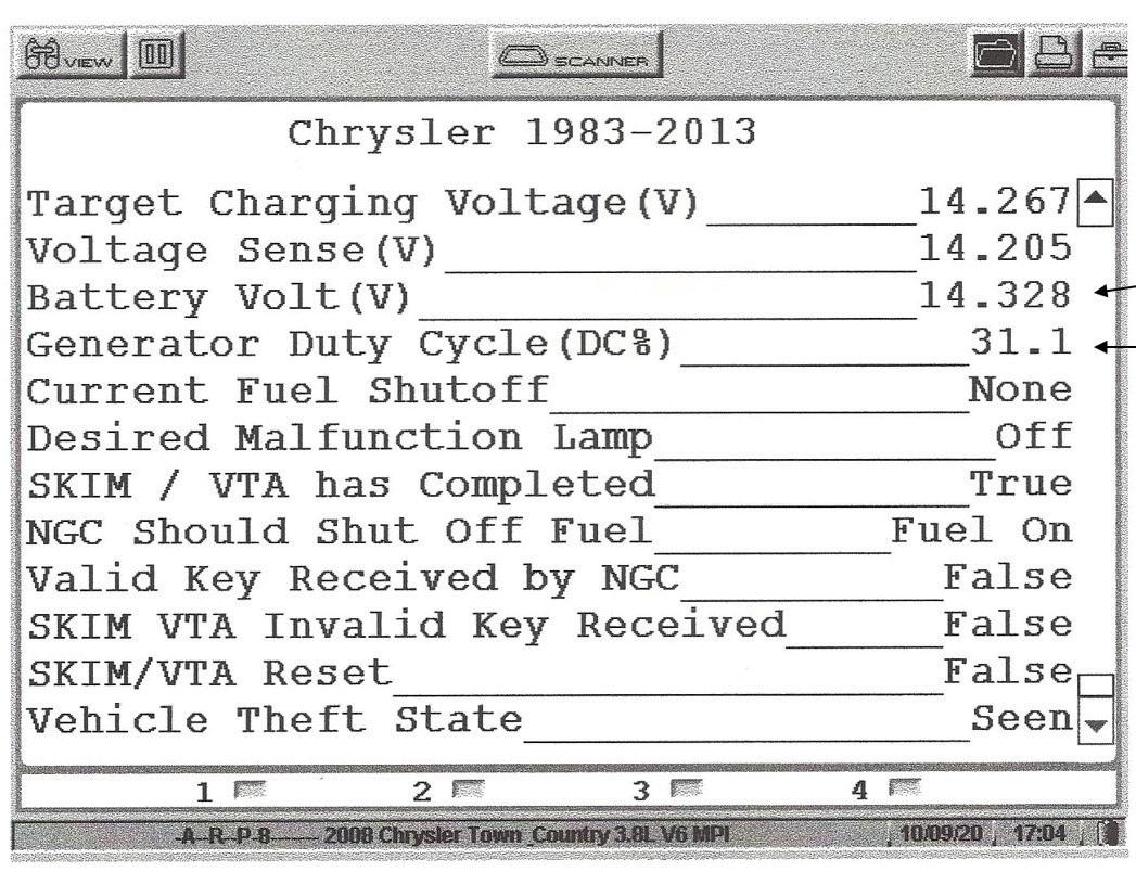
Fig 20: Example of where we can take control of the alternator during KOEO condition.
Fig 21: Information from the engine data packet shows a 31% duty cycle command to control the alternator during idle with no electrical load.
system and others. Many of these specific tests are done during KOER conditions.
Most technicians are aware of the diagnostic value of using the graphing mode of the scan tool when analyzing a specific sensor input.


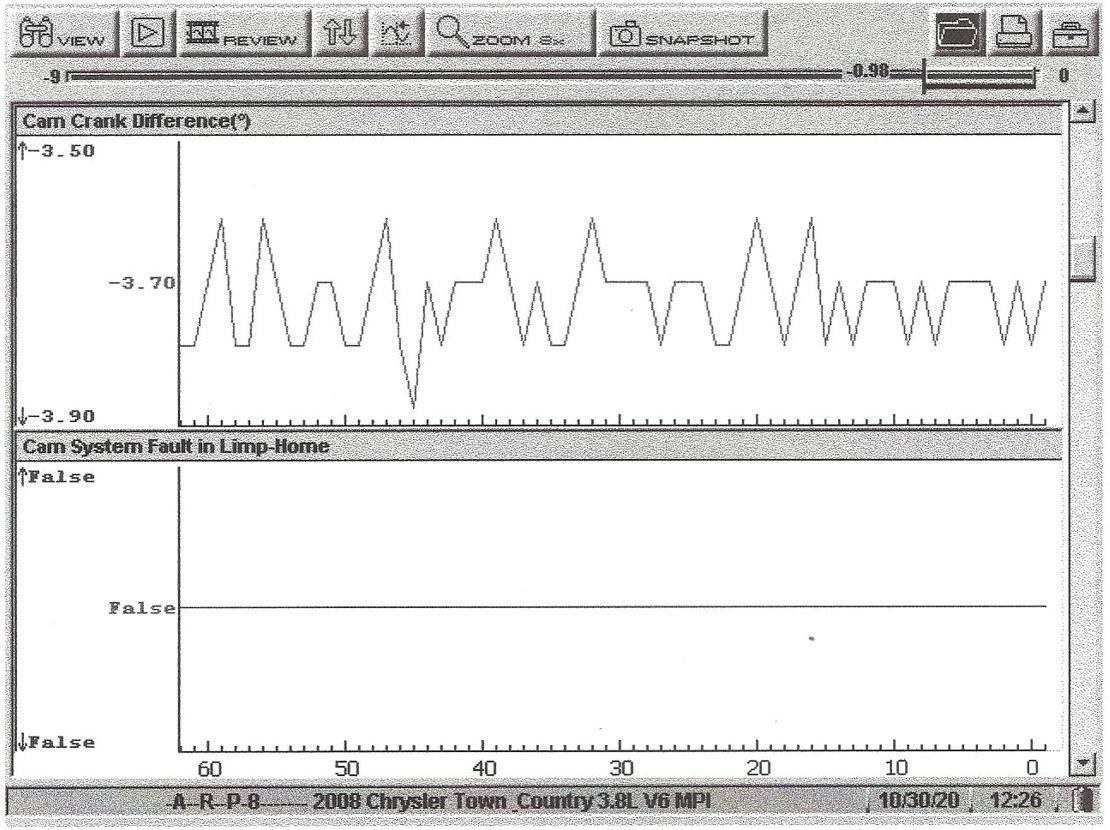
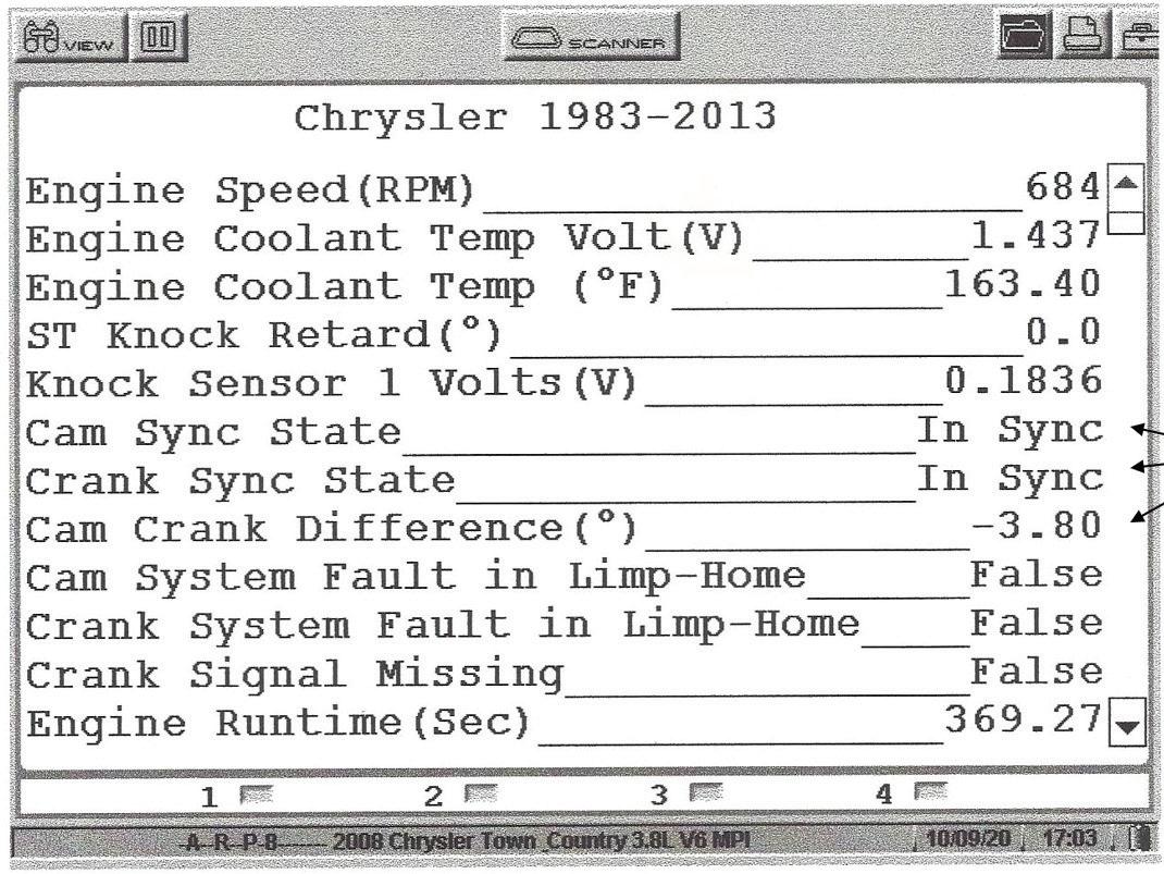
Fig. 11 is where we selected the ignition data packet. Notice the cam and crank sensor PIDs indicating in sync. In addition, the cam and crank variance indicates 3.8 degrees. Some of these PIDs can be graphed out for a better diagnostic. When doing this dynamically the sync and the cam and crank variance will not be stable until the RPM becomes stable. It’s easy to see that these PIDs are critical PIDs on the modern-day engines equipped with variable valve timing on the overhead cam equipped engines. When looking at these values dynamically in the graphing mode notice that the sync
state and the cam variance will not be stable as the RPM changes in Fig. 12.
Fig. 13 is a list of adaptive resets. For example, if an air fuel ratio problem has been corrected, we would select the fuel adaptive reset function during KOEO conditions. Notice in Fig. 13 we have highlighted the misfire adaptive numerator. This function is needed in the event a cam or crank sensor, fly wheel, the PCM,


36 ASP | JUNE 2023 CHRYSLER DIAGNOSTICS
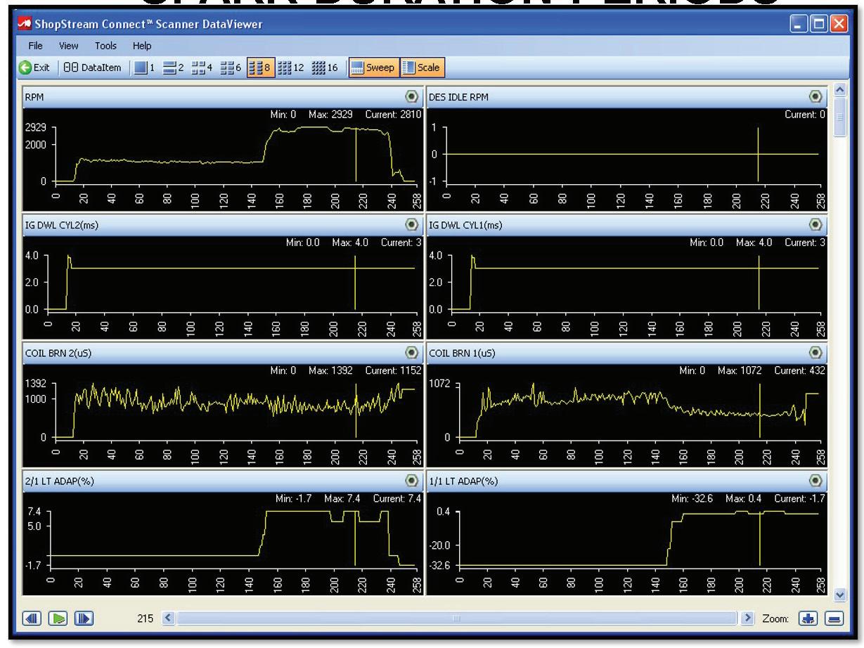
Fig 23: Example of the time for each coil’s magnetic field to collapse (the spark duration period).
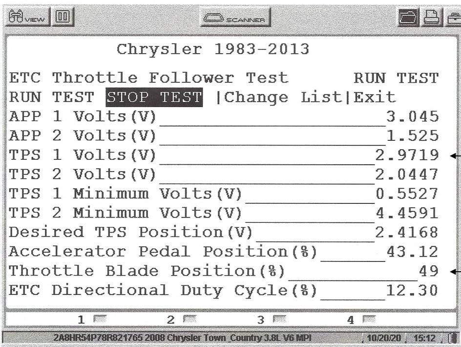
Fig 24: Example of selecting the ETC follower test from the system test menu.
Fig 25: APP and TPS values during half-throttle.
Fig 22: A battery failure will disable the stop start system and set a P057F code.
a timing chain, timing belt or the engine has been replaced. Failure to do so could result in false misfire codes. It is well documented that the adaptive memory resets by using an aftermarket scan tool sometimes do not work.
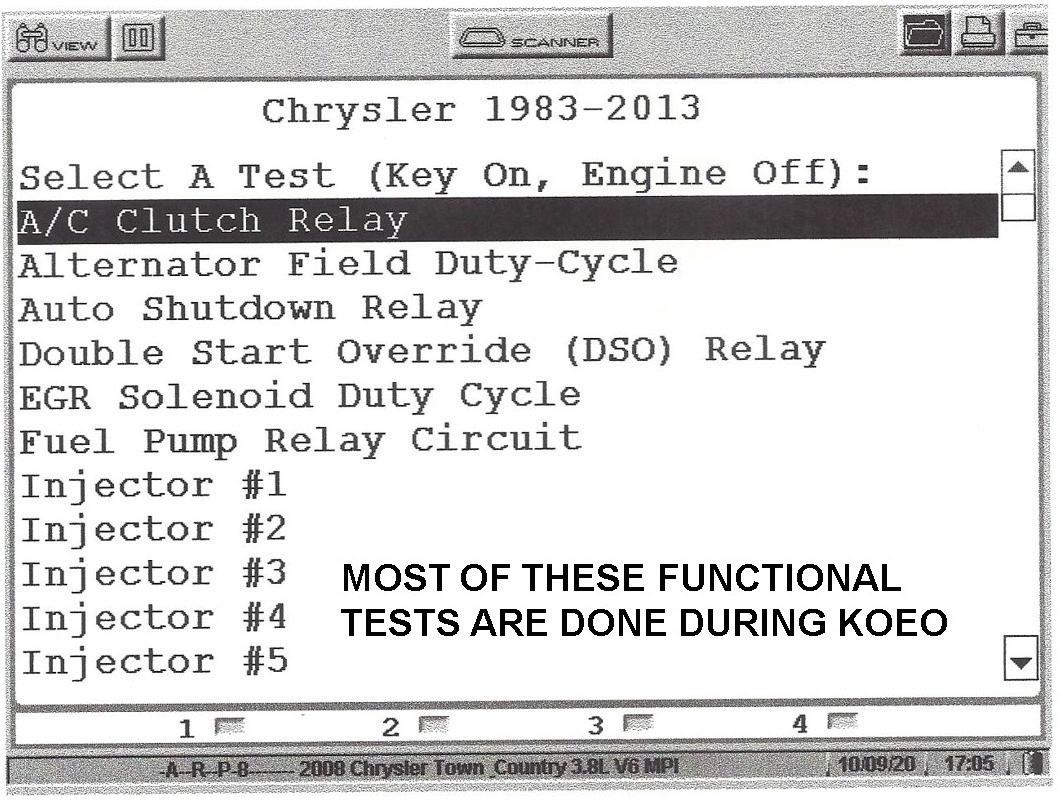
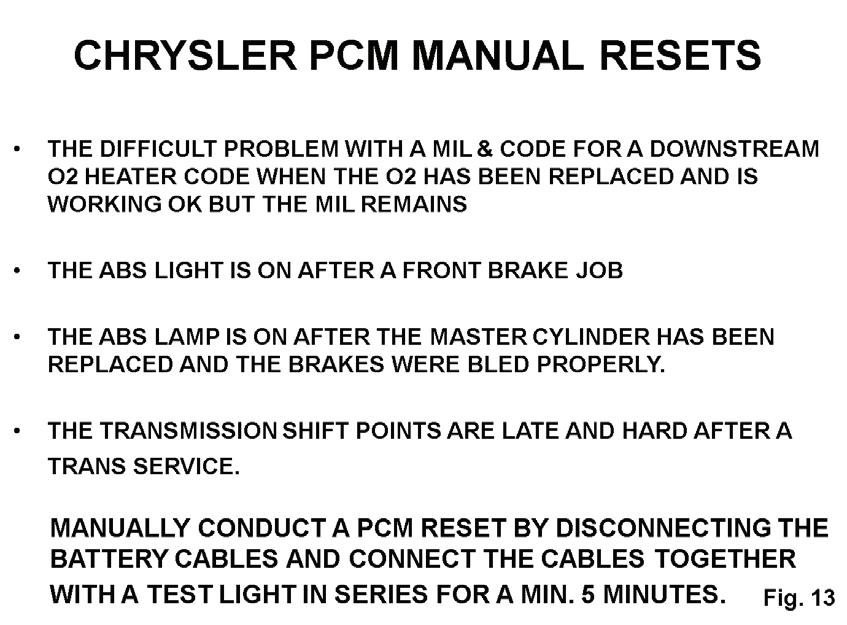
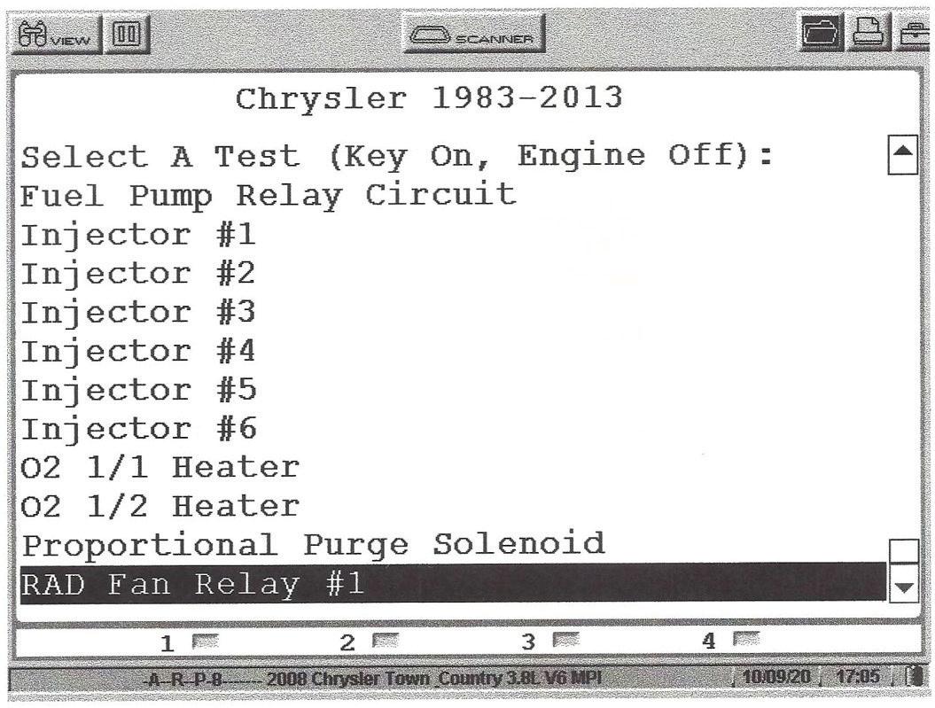
Let’s say the MIL cannot be cleared; we would first try mode 4 on the global side of the scan tool. If the MIL remains on or the ABS light remains on, we are showing the manual reset procedures in Fig. 14. If doing this procedure, keep in mind that the radio, clock settings and memory seat settings will be lost. Figs. 15 and Fig.16 show a list of the KOEO tests that are available under the functional test menu. These tests are listed under the functional test menu and most are done during KOEO conditions. On the system test menu the options are listed in Fig. 17. Many of these tests are done during KOER conditions. We highlighted the injector kill test which can be done during KOER conditions.
JUNE 2023 | ASP 37 Craig@fixhybrid.com www.fixhybrid.com (508)-826-4546 Tesla Training Hands On Training 3 Day Classes, Online Webinars, 8 Hour On The Road Classes ACDC is your ONE-STOP resource for Hybrid and Electric Vehicle Training needs! ACDC offers: • Hands On Tesla Classes • HEV-EV Classes • Webinars - Live and Recorded • Books • Safety Equipment 2304ASP_VanBatenburgsGarage.indd 1 3/20/23 9:12 AM
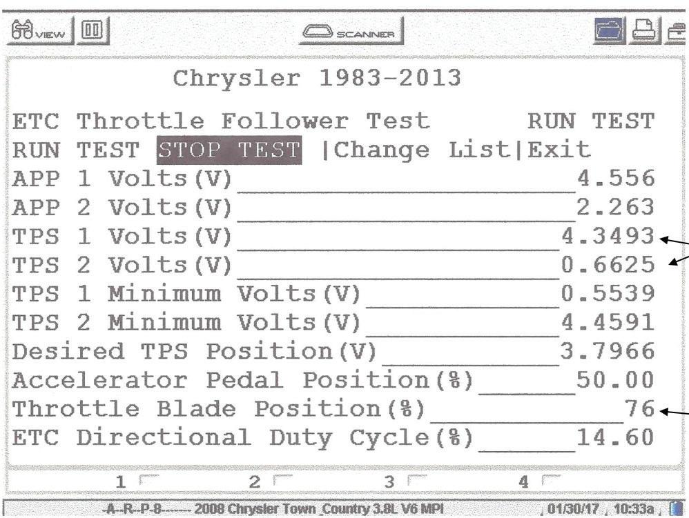
Fig 26: APP and TPS values during wide open throttle.
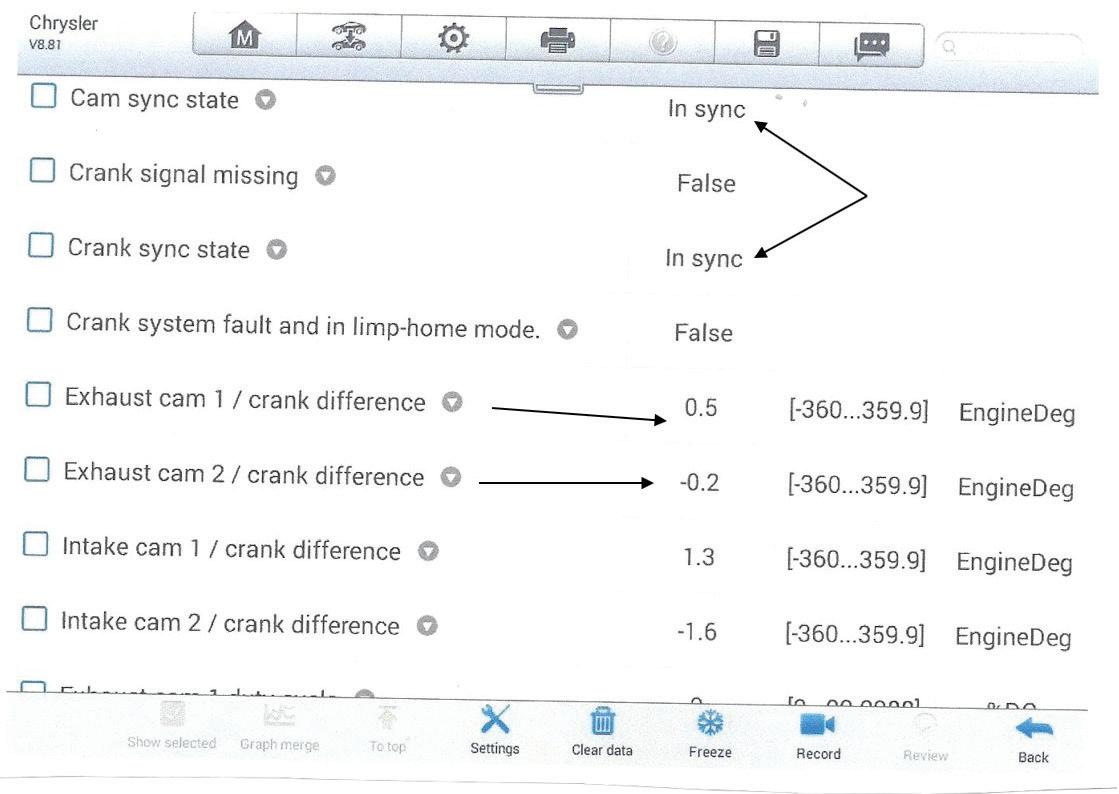
Fig 27: Scan data from a 3.6L DOHC engine at idle. Notice the cam and crank signals are in sync.
Fig 28: Cam data captured at off-idle while in Park. Note the 50% duty cycle command to the bank 1 exhaust cam control solenoid.
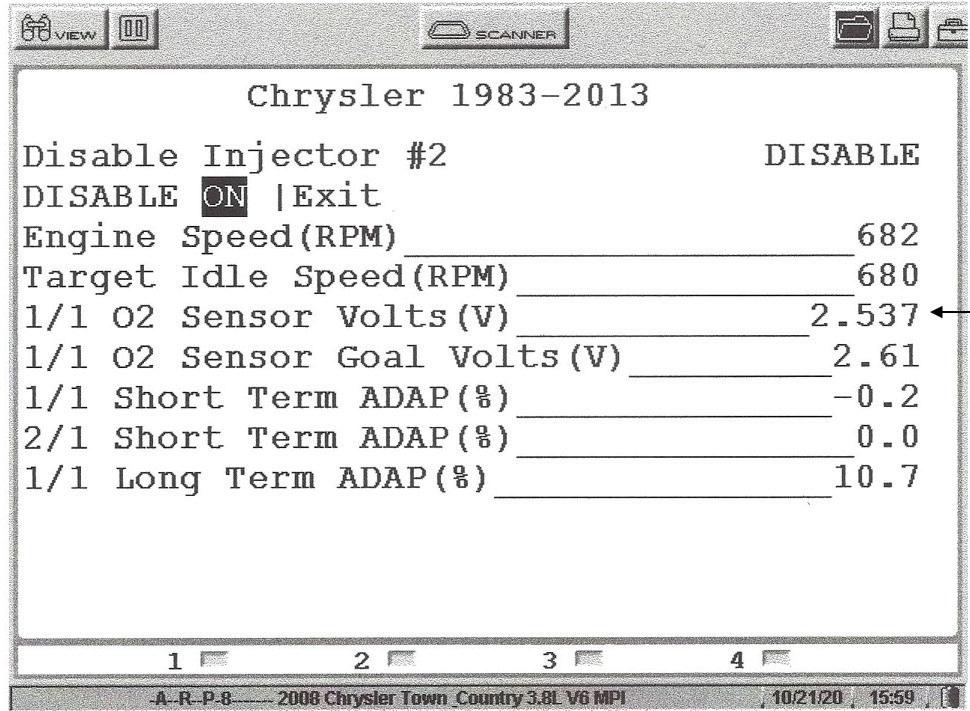
Chrysler began using a 5 volt bias voltage to the oxygen sensor way back in 1997 on the zirconium oxygen sensors. With the sensor plugged in during KOEO the loading effect pulls the voltage down to 2.5 volts. During KOER conditions voltages above 2.5 volts represent a rich condition while voltages below 2.5 volts represent a lean condition. Notice the oxygen voltage before an injector was disabled in Fig. 18. Now notice in Fig.19 the lean shift when an injector was disabled. In MY 2018
Chrysler began using an electronic fuel control module with an electronic fuel pressure sensor. On these systems we would simply monitor the fuel pressure drops when conducting the injector kill test.
In addition, the live misfire monitoring is available from the system test menu. Notwithstanding, remember from the Mode 6 menu on the global side of the scan tool individual cylinder misfires will be listed from the last 10 drive cycles. Fig. 20 shows where we can take control of the alternator during KOEO conditions. Most Chrysler alternators are feed side controlled, meaning the PCM will send out 12 volts to the F1 terminal of the alternator. Fig. 21 from the engine data packet shows a 31% duty cycle command to control the alternator during idle and no electrical load. Late model Chrysler vehicles equipped with start/stop technology will be equipped with an IBS (Intelligent Battery Sensor) which is mounted on the negative battery terminal. It reports battery state of charge during cranking and running condition to the BCM who then reports the data to the PCM. A failure of the battery will disable the stop/start system and set a PO57F code. See Fig. 22. Chrysler coils are controlled internally by the PCM. What you are seeing in Fig. 23 is the time for each coil’s magnetic field to collapse, which is essentially the spark duration period. However, we have determined that this data is good for individual coil time of magnetic collapse for comparison purposes only. When using a lab scope a good spark duration period during idle and no load conditions will be around 2 milliseconds. Notice that
38 ASP | JUNE 2023
CHRYSLER DIAGNOSTICS
Fig 30: The two types of Chrysler EVAP systems.
Fig 31: The large EVAP hose must be pinched off when performing a smoke test.
Fig 29: Check out the data related to the variable cam timing system (VVT oil pressure and oil temperature).
the No. 1 coil indicates a 0.8 millisecond spark duration period. Though this data is not entirely correct, it did indicate that the coil’s spark duration period was significantly shorter than the other cylinders. This data was captured from a Chrysler 3.6L engine with 79,000 miles on the odometer, well short of the factory recommendation for spark plug changes. Fig. 24 is where we selected the ETC follower test from the system test menu. This test is done during KOEO conditions. Fig. 25 indicates the APP and TPS value during half throttle while Fig. 26 indicates the APP and TPS values during WOT conditions. The key here is that the TPS 1 and the TPS 2 voltage values will always add up to 5 volts, no matter the angle of the gas pedal if the system is performing properly. This test is done during KOEO conditions.
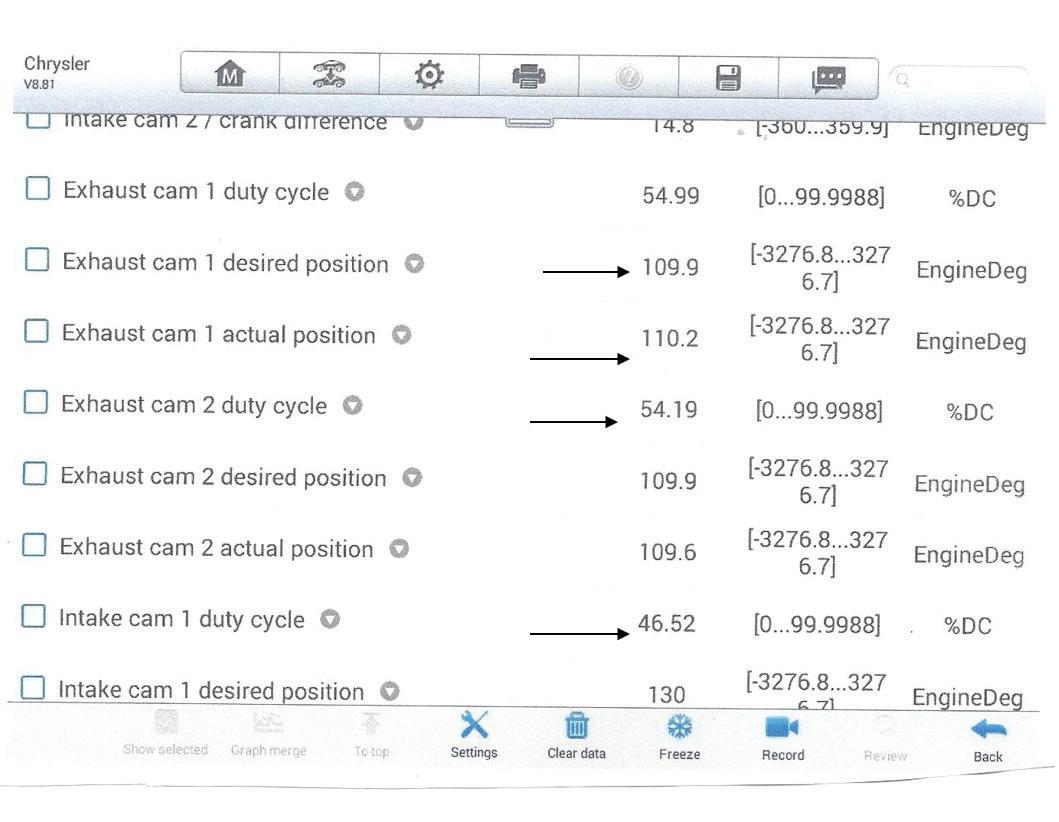
Chrysler has gone to variable cam timing on most of their engines beginning in MY 2012. Fig. 27 is scan data from a 3.6L DOHC engine captured at idle. Notice the scan tool data indicates the cam and crank are in sync. In addition, notice the variance values of both exhaust and intake cams. This was captured at idle where the duty cycle command to the VVT control solenoids is indicating 0%. Unlike GM, the Chrysler PCM will vary the cam timing during park conditions and off idle. Fig. 28 is cam data captured at off idle conditions while in Park. Notice the 50% duty cycle command to the bank
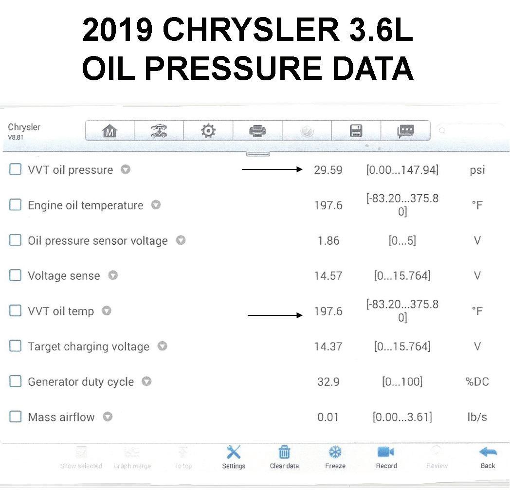
1 exhaust cam control solenoid. The data also indicated the actual and desired position of the cams in degrees of crank rotation. Fig. 29 indicates some important data related to the variable cam timing system as in VVT oil pressure and VVT oil temperature.
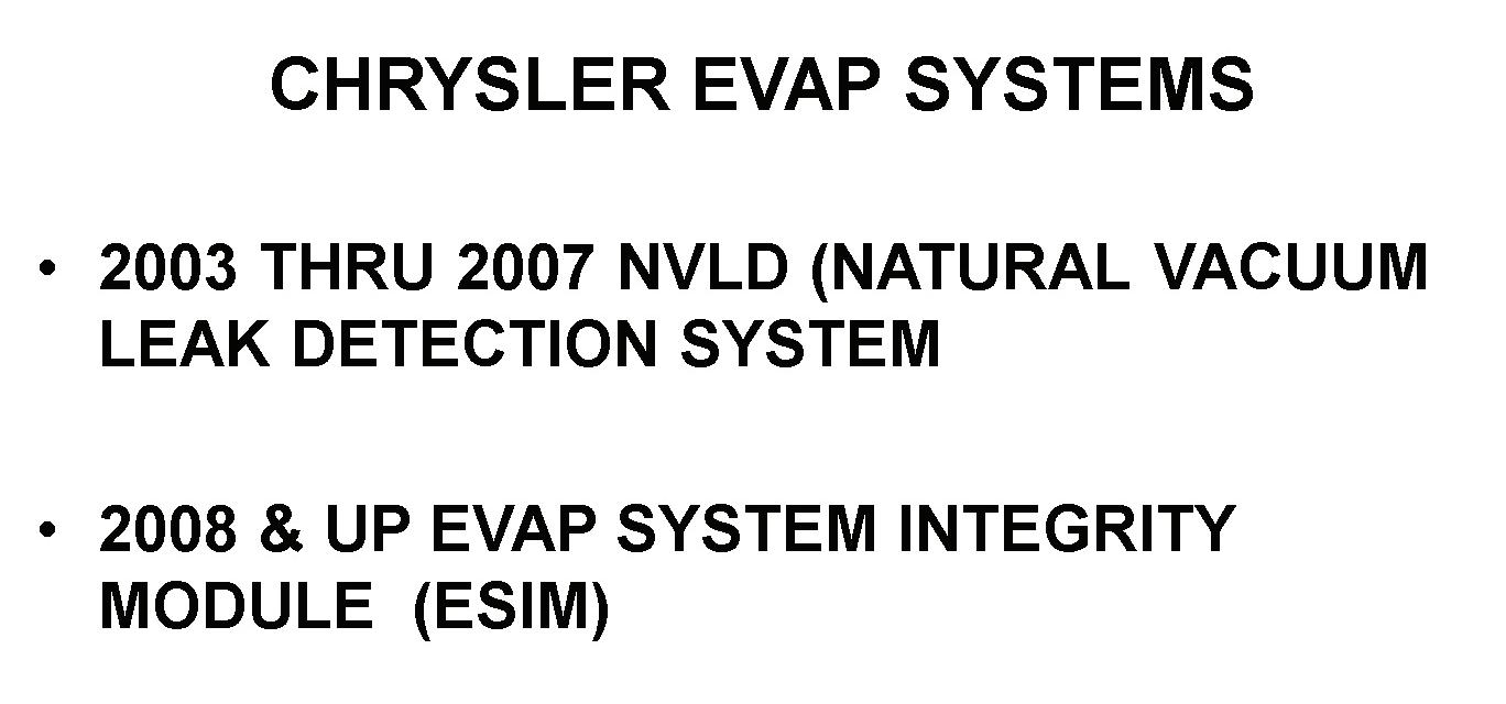
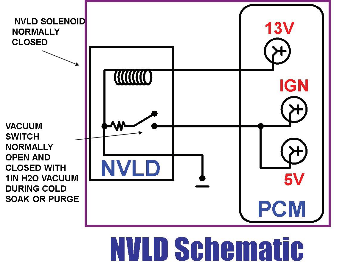
There are two types of EVAP Systems as seen in Fig. 30. These two systems are remarkably similar. The NVLD (Natural Vacuum Leak Detection) is a sealed system during KOEO. The PCM conducts a small leak monitor during an over-extended cold soak during a key off condition. As the EVAP system cools down and is sealed, a natural vacuum builds. When a value of 1 inch of water vacuum is reached, a vacuum switch closes and pulls a voltage supplied to the vacuum switch to ground. When the PCM sees this voltage pulled to ground the small leak monitor has passed. If the vacuum switch never closes and the voltage remains either 5 or 12 volts, the PCM will run the EVAP monitor on the next drive cycle by ramping up the duty cycle command to the purge solenoid, thus building vacuum and closing the vacuum switch. At that point the PCM turns off the purge solenoid which is now closed. If a leak exists, vacuum will bleed off and the PCM will set a medium or large leak code. If the system is totally sealed and vacuum remains, the PCM will energize the NVLD solenoid to bleed off the excessive vacuum. Since the NVLD solenoid is closed in a de-energized condition the system
JUNE 2023 | ASP 39
Fig 32: Schematic of the NVLD system.
Fig 33: Scan tool indication that an EVAP monitor is available.
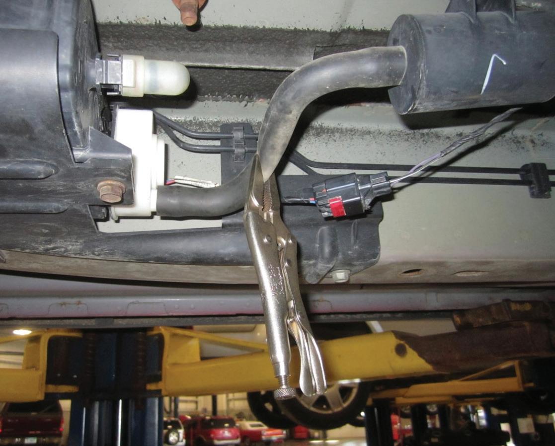
is sealed during KOEO conditions. When smoke testing these systems, the large rubber hose would need to be pinched off since some smoke machines may produce more than 6 inches of water and a pressure relief valve will open and bleed off the excessive smoke machine pressure. See Fig. 31. A schematic of the NVLD system is indicated in Fig. 32.
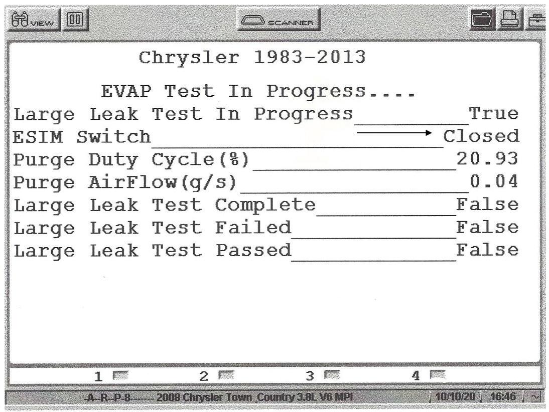
Fig. 33 indicates that an EVAP monitor is available from the scan tool to do a service bay EVAP monitor. If an EVAP code exists, it must be cleared before running the service bay EVAP monitor. If the code repeats, then a hard code exists. The problem here is that the EVAP monitor cannot detect a small leak code. In Fig. 34 the screen shows the results from the service bay EVAP monitor as the vacuum switch indicates closed.
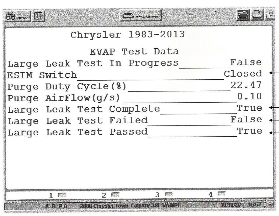
Fig. 35 shows a layout of the ESIM (Evaporative System Integrity Module) unit. This unit is part of the canister unit. It contains two weights, one small and one large. The small, weighted check will seal the system and then vent vacuum above 4 to 6 inches of water. The large, weighted check valve is designed to open and vent fuel vapors to the canister like during a refueling process. During key off conditions the ESIM system is sealed. As the fuel tank cools down, a natural vacuum is generated. When the vacuum reaches 1 inch of water the vacuum switch will close which pulls the voltage to ground. This means that the small leak monitor has passed. If the vacuum switch never closes, then on the next drive cycle the PCM will ramp up the duty cycle command to the purge solenoid thus building vacuum

and forcing the vacuum switch to close. The PCM will turn off the purge solenoid which locks vacuum in the EVAP system.

Depending on how long it takes for the vacuum to decay, causing the vacuum switch to go back to the open position, the PCM can time the value and determine whether a large or medium leak exists. When smoke testing this system, the large vent hose coming off the canister must be pinched off.
Hopefully we conveyed the robust data and functional tests and system tests available on the Powertrain side of the Chrysler/Jeep systems. In a future article we hope to cover the vast data from the TIPM module and functions and data from the TCM.
The industry is better because of your commitment.
Bill Fulton is the author of Mitchell 1’s Advanced Engine Performance Diagnostics and Advanced Engine Diagnostics manuals. He is also the author of several lab scope and drivability manuals such as Ford, Toyota, GM and Chrysler OBD I and OBD II systems, fuel system testing, many other training manuals in addition to his own 101 Lab Scope Testing Tips. He is a certified Master Technician with over 30 years of training and R&D experience. He was rated in the top three nationally on Motor Service magazine’s Top Technical Trainer Award and has instructed for Mitchell 1, Precision Tune, OTC, O’Reilly Auto Parts, BWD, JD Byrider, Snap-on Vetronix and Standard Ignition programs. You may have also seen Fulton in many Lightning Bolt Training videos and DVDs and read his articles in many auto service magazines. He currently owns and operates Ohio Automotive Technology, which is an automotive repair and research development center.
40 ASP | JUNE 2023 CHRYSLER DIAGNOSTICS
Fig 35: Layout of the ESIM unit.
Fig 34: Results from the service bay EVAP monitor as the vacuum switch indicates closed.
bulleTInS
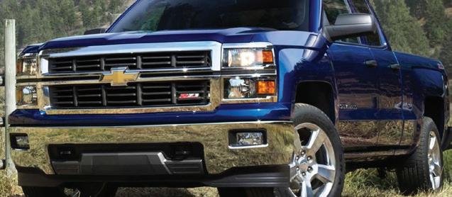
Package (RPO 5W4) and specified with a 170-amp generator may have been built with a 150 amp generator, resulting in an undersized charging system. This may result in a lower battery state of charge during periods of continuous high electrical loads. If the customer is experiencing unusual battery charge, check the generator to see if it’s the correct 170-amp model.
BUICK BUSHING NUTS
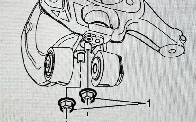
This bulletin applies to 2011-2015 Buick Allure, LaCrosse and Regal vehicles equipped with the performance strut assemblies. Some customers may comment on a click, pop or clunk noise from the front suspension while braking or driving over bumps at low speed when turning. This may be caused by a loss of clamp load at the lower revolute joint (king pin bushing) at the knuckle attachment. Remove the front suspension lower control arm and inspect the torque on the king pin bushing nuts. If torque is not at least 45 ft-lb, replace the king pin bushings and nuts for both strut assemblies. When installing the new bushing nuts, torque the nuts once, then remove the nuts and apply liquid thread locker P/N 8902 1297 to the king pin bushing studs. Re-torque the new nuts to 74 ft-lb.
FORD DIESEL INJECTOR KNOCK
Some 2017 Ford F-Super Duty trucks equipped with a 6.7L diesel engine may exhibit a fuel knock type noise at idle, MIL on, and one or more of the following DTCs in the PCM memory: P0263, P0266, P0269, P0272, P0275, P0278, P0281, P0284, P2B11, P2B13, P2B15, P2B17, P2B19, P2B1B, P2B1D and/or P2B1F. This may be due to incorrect learning of the injector timing within the PCM.

Using IDS or FJDS, enter PCM datalogger and select the following parameter identifications (PIDs):
• ECT1 (temp)
• EGRVPDES#
• EOT
• RPMDSD#
• VGTDC#
CHEVY CHECK THE GENERATOR
Certain 2015 Chevy Silverado crew cab trucks equipped with Special Service
Using active command, select RPM# PID and increase engine speed to 1,500 RPM for two minutes. Hold engine speed at 1,500 RPM and command EGRVPDES# to lowest value and VGTDC close to about 60% to ensure ECT1 (engine coolant temperature) and EOT (engine oil temperature) are above
176 F. Once ECT1 and EOT reach 176 F, return engine speed to idle. Release command from the other parameters.
Perform the manual injector balance test under toolbox>powertrain>power balance. If the noise goes away when running the injector balance test, then select toolbox>powertrain>service functions. Reset fuel system — high pressure side, minimum fuel mass adaptation/all cylinders and crankshaft position sensor. Clear all DTCs. Reprogram the PCM using release 107.06 or higher.
HONDA REMAN TRANS
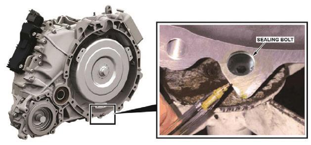
Because of a transmission case flaw for 2016-2017 Honda Pilot vehicles, the inside of the torque converter bracket hole in some 9-speed automatic transmissions is porous enough to allow ATF to leak from the hole. This flaw was found by the transmission factory during production.
As a temporary fi x, the factory installed a sealing bolt in the hole and it’s proven effective. That casting issue has since been resolved, and later castings don’t have the issue. So, the sealing bolt is no longer needed. If you order a reman A/T and its serial number is higher than what’s listed in the accompanying chart, don’t worry about a missing sealing bolt.
JUNE 2023 | ASP 41
TeChnICal ServICe
MODEL
2016-2017 Pilot 2WD Q5NB0116449 2016-2017 Pilot 4WD Q5NC0133827
Information courtesy of Mitchell 1
DRIVE TYPE SERIAL NUMBER

42 ASP | JUNE 2023 ACDC 37 www.fixhybrid.com Aftermarket Auto Parts Alliance Inc. 19 www.perfectstopsummerpromo.com Aftermarket Auto Parts Alliance Inc. 23 www.myplace4parts.com Autel 5 www.autel.com AutoZone Inc. OBC www.autozonepro.com BendPak Inc. 15 www.bendpak.com Continental 13 www.continentalaftermarket.com Delphi Technologies 33 www.delphiaftermarket.com Federated Auto Parts 9 www.federatedautoparts.com Launch Tech USA 25 www.launchtechusa.com Lang Tools 31 www.langtools.com O’Reilly Auto Parts 16-17 www.firstcallonline.com Power Probe 35 www.powerprobe.com Robinair 21 www.robinair.com Shurtape Technologies LLC 27 www.frogtape.com/performance TEXA USA IBC www.texausa.com autojobcentral.com USE CODE: AJC123 TO TAKE $100 OFF YOUR FIRST LISTING! POST A JOB RECEIVE QUALIFIED APPLICANTS GROW YOUR TEAM 1 2 3 AS EASY AS... AD INDEX


44 ASP | JUNE 2023
AutoZone, Inc.
AutoZone, AutoZone & Design,
Duralast
of AutoZone IP LLC or one of its affiliates. All other
their respective owners. All photographic, clerical, typographical and other errors are subject to correction.
bundle and noise free guarantee requires the purchase of any set of Duralast, Duralast Gold, Duralast Elite pads, 2 Duralast or Duralast Gold rotors and hardware (when available) on the same invoice. Guarantee covers parts and labor for 90 days when professionally installed. SEE THE DIFFERENCE TODAY REPAIR WITH DURALAST. REPAIR WITH CONFIDENCE. SLOTS AND CHAMFERS OE STYLE SHIMS OE FRICTION FORMULATIONS OE SHOP EXCLUSIVE BRAKE BUNDLE* PRICING ON AUTOZONEPRO.COM/BRAKES
©2023
All rights reserved.
and
are registered marks
marks are the property of
*Brake
