Pavement Analysis and Design
Second Edition
Yang H. Huang
Vice President and Editorial Director, ECS : Marcia Horto n
Acquisitions Editor: Laura Fischer
Editorial Assistant: Andrea Messineo
Vice President and Director of Production and Manufacturing, ESM : David W. Riccardi
Executive Managing Editor : Vince O'Brien
Managing Editor : David A. George
Production Editor : Rose Kernan
Director of Creative Services : Paul Belfanti
Creative Director : Carole Anson
Art Director : Jayne Conte
Art Editor: Gregory Dulles
Cover Designer : Bruce Kenselaar
Manufacturing Manager: Trudy Pisciotti
Manufacturing Buyer: Lisa McDowell
Marketing Manager: Holly Stark
PEARSON
Prentic e Hall 2004 by Pearson Education, Inc
Pearson Prentice Hall
Pearson Education, Inc . Upper Saddle River, NJ 0745 8
All rights reserved. No part of this book may be reproduced in any form or by any means, without permission in writing from the publisher
Pearson Prentice Hall is a trademark of Pearson Education, Inc
The author and publisher of this book have used their best efforts in preparing this book . These efforts include the development, research, and testing of the theories and programs to determine their effectiveness . The author and publisher make no warranty of any kind, expressed or implied, with regard to these programs or the documentation contained in this book. The author and publisher shall not be liable in any event for incidental or consequential damages i n connection with, or arising out of, the furnishing, performance, or use of these programs
Printed in the United States of Americ a
10 9 8 7 6 5
ISBN 0-13-142473- 4
Pearson Education Ltd ., London
Pearson Education Australia Pty. Ltd., Sydney
Pearson Education Singapore, Pte. Ltd.
Pearson Education North Asia Ltd ., Hong Kon g
Pearson Education Canada, Inc ., Toronto
Pearson Educacion de Mexico, S.A. de C.V .
Pearson Education—Japan, Tokyo
Pearson Education Malaysia, Pte . Ltd
Pearson Education, Inc., Upper Saddle River, New Jersey
4.3 Stresses Due to Friction
4.4 Design of Dowels and Joints Summary Problems
CHAPTER 5 KENSLABS Computer Progra m
5 .1 Theoretical Developments
5 .2 Program Description
5 .3 Comparison with Available Solutions
5.4 Sensitivity Analysis Summary Problems
CHAPTER 6 Traffic Loading and Volume
6.1 Design Procedures
6.2 Equivalent Single-Wheel Load
6.3 Equivalent Axle Load Factor
6.4 Traffic Analysis Summary Problems
CHAPTER 7 Material Characterization
7.1 Resilient Modulus
7.2 Dynamic Modulus of Bituminous Mixtures
7.3 Fatigue Characteristics
7.4 Permanent Deformation Parameter s
7.5 Other Properties Summary Problems
CHAPTER 8 Drainage Design
8.1 General Consideration
8.2 Drainage Materials
8.3 Design Procedures Summary Problems
CHAPTER 9 Pavement Performance
9.1 Distress
9.2 Serviceability
9.3 Surface Friction
Introduction
1 .1 HISTORICAL DEVELOPMENTS
Although pavement design has gradually evolved from art to science, empiricism stil l plays an important role even up to the present day. Prior to the early 1920s, the thickness of pavement was based purely on experience. The same thickness was used for a section of highway even though widely different soils were encountered. As experience was gained throughout the years, various methods were developed by different agencie s for determining the thickness of pavement required. It is neither feasible nor desirable to document all the methods that have been used so far. Only a few typical methods will be cited to indicate the trend
Some technical terms will be used in this introductory and review chapter . It is presumed that the students using this book as a text are seniors or graduate students who have taken courses in transportation engineering, civil engineering materials, and soil mechanics and are familiar with these terms. In case this is not true, these terms can be ignored for the time being, because most are explained and clarified in later chapters.
1 1 .1 Flexible Pavements
Flexible pavements are constructed of bituminous and granular materials . The first asphalt roadway in the United States was constructed in 1870 at Newark, New Jersey
The first sheet-asphalt pavement, which is a hot mixture of asphalt cement with clean, angular, graded sand and mineral filler, was laid in 1876 on Pennsylvania Avenue in Washington, D.C., with imported asphalt from Trinidad Lake. As of 2001 (FHWA, 2001), there are about 2.5 million miles of paved roads in the United States, of which 94% are asphalt surfaced
Design Methods
Methods of flexible pavement design can be classified into five categories: empirical method with or without a soil strength test, limiting shear failur e method, limiting deflection method, regression method based on pavement performance or road test, and mechanistic–empirical method .

Empirical Methods The use of the empirical method without a strength test dates back to the development of the Public Roads (PR) soil classification system (Hogentogler and Terzaghi, 1929), in which the subgrade was classified as uniform fro m A-1 to A-8 and nonuniform from B-1 to B-3 . The PR system was later modified by the Highway Research Board (HRB, 1945), in which soils were grouped from A-1 to A- 7 and a group index was added to differentiate the soil within each group. Steele (1945) discussed the application of HRB classification and group index in estimating the subbase and total pavement thickness without a strength test . The empirical method with a strength test was first used by the California Highway Department in 1929 (Porter , 1950). The thickness of pavements was related to the California Bearing Ratio (CBR), defined as the penetration resistance of a subgrade soil relative to a standard crushe d rock. The CBR method of design was studied extensively by the U.S. Corps of Engineers during World War II and became a very popular method after the war . The disadvantage of an empirical method is that it can be applied only to a give n set of environmental, material, and loading conditions. If these conditions are changed, the design is no longer valid, and a new method must be developed through trial an d error to be conformant to the new conditions.
Limiting Shear Failure Methods
The limiting shear failure method is used t o determine the thickness of pavements so that shear failures will not occur . The major properties of pavement components and subgrade soils to be considered are their cohesion and angle of internal friction. Barber (1946) applied Terzaghi's bearing capacity formula (Terzaghi, 1943) to determine pavement thickness . McLeod (1953) advocated the use of logarithmic spirals to determine the bearing capacity of pavements. These methods were reviewed by Yoder (1959) in his book Principles of Pavement Design, but were not even mentioned in the second edition (Yoder and Witczak, 1975) . This is not surprising because, with the ever increasing speed and volume of traffic, pavements should be designed for riding comfort rather than for barely preventing shear failures
Limiting Deflection Methods
The limiting deflection method is used to determine the thickness of pavements so that the vertical deflection will not exceed the allowable limit. The Kansas State Highway Commission (1947) modified Boussinesq's equatio n (Boussinesq, 1885) and limited the deflection of subgrade to 0.1 in. (2.54 mm). The U.S Navy (1953) applied Burmister's two-layer theory (Burmister, 1943) and limited the surface deflection to 0.25 in. (6.35 mm) . The use of deflection as a design criterion has the apparent advantage that it can be easily measured in the field . Unfortunately, pavement failures are caused by excessive stresses and strains instead of deflections
Regression Methods Based on Pavement Performance or Road Tests A good example of the use of regression equations for pavement design is the AASHTO method based on the results of road tests. The disadvantage of the method is that the desig n equations can be applied only to the conditions at the road test site. For conditions other than those under which the equations were developed, extensive modifications based o n theory or experience are needed . Regression equations can also be developed from the performance of existing pavements, such as those used in the pavement evaluatio n systems COPES (Darter et al., 1985) and EXPEAR (Hall et aL,1989) . Unlike pavements
subjected to road tests, the materials and construction of these pavements were not well controlled, so a wide scatter of data and a large standard error are expected . Although these equations can illustrate the effect of various factors on pavemen t performance, their usefulness in pavement design is limited because of the man y uncertainties involved .
Mechanistic–Empirical Methods
The mechanistic–empirical method of desig n is based on the mechanics of materials that relates an input, such as a wheel load, to a n output or pavement response, such as stress or strain . The response values are used to predict distress from laboratory-test and field-performance data . Dependence o n observed performance is necessary because theory alone has not proven sufficient t o design pavements realistically
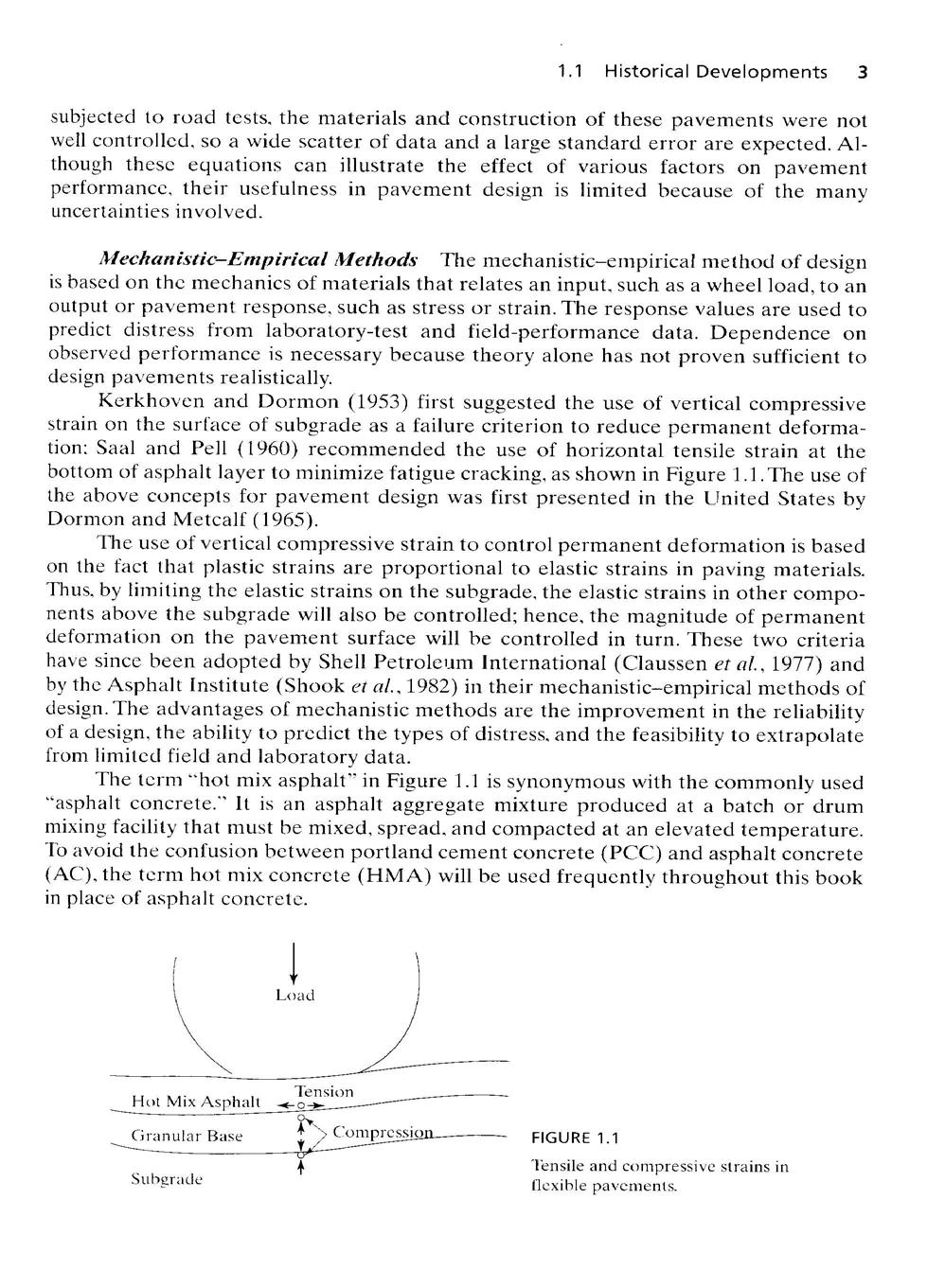
Kerkhoven and Dormon (1953) first suggested the use of vertical compressive strain on the surface of subgrade as a failure criterion to reduce permanent deformation: Saal and Pell (1960) recommended the use of horizontal tensile strain at th e bottom of asphalt layer to minimize fatigue cracking, as shown in Figure 1 .1 . The use of the above concepts for pavement design was first presented in the United States b y Dormon and Metcalf (1965)
The use of vertical compressive strain to control permanent deformation is based on the fact that plastic strains are proportional to elastic strains in paving materials. Thus, by limiting the elastic strains on the subgrade, the elastic strains in other components above the subgrade will also be controlled ; hence, the magnitude of permanent deformation on the pavement surface will be controlled in turn . These two criteria have since been adopted by Shell Petroleum International (Claussen et al., 1977) and by the Asphalt Institute (Shook et al., 1982) in their mechanistic–empirical methods of design . The advantages of mechanistic methods are the improvement in the reliability of a design, the ability to predict the types of distress, and the feasibility to extrapolat e from limited field and laboratory data
The term "hot mix asphalt" in Figure 1 .1 is synonymous with the commonly use d "asphalt concrete." It is an asphalt aggregate mixture produced at a batch or dru m mixing facility that must he mixed, spread, and compacted at an elevated temperature . To avoid the confusion between portland cement concrete (PCC) and asphalt concrete (AC) . the term hot mix concrete (HMA) will be used frequently throughout this boo k in place of asphalt concrete .
and compressive strains i n
FIGURE 1 . 1
Other Developments
Other developments in flexible pavement design include th e application of computer programs, the incorporation of serviceability and reliability , and the consideration of dynamic loading
Computer Programs
Various computer programs based on Burmister's layered theory have been developed. The earliest and the best known is the CHEV program developed by the Chevron Research Company (Warren and Dieckmann, 1963) . The program can be applied only to linear elastic materials but was modified by the Asphal t Institute in the DAMA program to account for nonlinear elastic granular materials (Hwang and Witczak, 1979). Another well-publicized program is BISAR, developed b y Shell, which considers not only vertical loads but also horizontal loads (De Jong et al , 1973). Another program, originally developed at the University of California, Berkeley , and later adapted to microcomputers, is ELSYM5, for elastic five-layer systems unde r multiple wheel loads (Kopperman et al., 1986). Using the layered theory with stressdependent material properties, Finn et al (1986) developed a computer program name d PDMAP (Probabilistic Distress Models for Asphalt Pavements) for predicting the fatigue cracking and rutting in asphalt pavements. They found that the critical responses obtained from PDMAP compared favorably with SAPIV, which is a finite-element stres s analysis program developed at the University of California, Berkeley. Khazanovich and loannides (1995) developed a computer program (calle d DIPLOMAT) in which the Burmister's multilayered system was extended to include a number of elastic plates and spring beds. The program in its present form deals only with interior loading and is therefore of limited application, because a rigid layer o f concrete can be considered as one of the multilayers, as illustrated in Section 5 .3 .4, and there is really no need to treat the concrete slab as a separate plate unless the load is applied near an edge or a discontinuous boundary.
A major disadvantage of the layered theory is the assumption that each layer is homogeneous with the same properties throughout the layer. This assumption makes it difficult to analyze layered systems composed of nonlinear materials, such as untreated granular bases and subbases. The elastic modulus of these materials is stress dependent and varies throughout the layer, so a question immediately arises : Which point in the nonlinear layer should be selected to represent the entire layer? If only the most critica l stress, strain, or deflection is desired, as is usually the case in pavement design, a point near to the applied load can be reasonably selected. However, if the stresses, strains, or deflections at different points, some near to and some far away from the load, are desired , it will be difficult to use the layered theory for analyzing nonlinear materials . This difficulty can be overcome by using the finite-element method. Duncan et al (1968) first applied the finite-element method for the analysis of flexible pavements. The method was later incorporated in the ILLI-PAVE computer progra m (Raad and Figueroa, 1980). The large amount of computer time and storage require d means that the program has not been used for routine design purposes . However, a number of regression equations, based on the responses obtained by ILLI-PAVE, were developed for use in design (Thompson and Elliot, 1985 ; Gomez-Achecar and Thompson, 1986). The nonlinear finite-element method was also used in the MICH-PAVE computer program developed at Michigan State University (Harichandran et al., 1989). More information about ILLI-PAVE and MICH-PAVE is presented in Section 3 .3 .2.

Serviceability and Reliability As a result of the AASHO Road Test, Carey and Irick (1960) developed the pavement serviceability performance concept and indicated that pavement thickness should also depend on the terminal serviceabilit y index required. Lemer and Moavenzadeh (1971) presented the concept of reliability as a pavement design factor, and a probabilistic computer program called VESYS wa s developed for analyzing a three-layer viscoelastic pavement system (Moavenzade h et a1.,1974) . This program, which incorporated the concepts of serviceability and reliability, was modified by the Federal Highway Administration (FHWA, 1978 ; Kenis, 1977), and several versions of the VESYS program were developed (Lai, 1977; Rauhut and Jordahl, 1979 ; Von Quintus, et al., 1988; Jordahl and Rauhut, 1983 ; Brademeyer, 1988) . The reliability concept was also incorporated in the Texas flexible pavement design system (Darter et al., 1973b) and in the AASHTO Design Guide (AASHTO, 1986) . Although the AASHTO procedures are basically empirical, the replacements of the empirical soil support value by the subgrade resilient modulus an d the empirical layer coefficients by the resilient modulus of each layer clearly indicate the trend toward mechanistic methods . The resilient modulus is the elastic modulu s under repeated loads ; it can be determined by laboratory tests. Details about resilient modulus are presented in Section 7.1, serviceability in Section 9 .2, and reliability in Chapter 10
Dynamic Loads
All of the methods discussed so far are based on static or movin g loads and do not consider the inertia effects due to dynamic loads . Mamlouk (1987) described a computer program capable of considering the inertial effect and indicated tha t the effect is most pronounced when shallow bedrock or frozen subgrade is encountered ; it becomes more important for vibratory than for impulse loading. The program require s a large amount of computer time to run and is limited to the analysis of linear elastic materials. The inclusion of inertial effect for routine pavement design involving nonlinear elastic and viscoelastic materials is still a dream to be realized in the future
Research by Monismith et al (1988) showed that, for asphalt concrete pavements, it was unnecessary to perform a complete dynamic analysis. Inertia effects can be ignored and the local dynamic response can thus be determined by an essentially static metho d using material properties compatible with the rate of loading . However, under impulse loading, a dynamic problem of more immediate interest is the effect of vehicle dynamic s on pavement design. Current design procedures do not consider the damage caused by pavement roughness. As trucks become larger and heavier, some benefits can be gaine d by designing proper suspension systems to minimize the damage effect .
1 .1 .2 Rigid Pavements
Rigid pavements are constructed of Portland cement concrete . The first concrete pavement was built in Bellefontaine, Ohio in 1893 (Fitch, 1996), 15 years earlier than th e one constructed in Detroit, Michigan, in 1908, as mentioned in the first edition . As of 2001, there were about 59,000 miles (95,000 km) of rigid pavements in the Unite d States. The development of design methods for rigid pavements is not as dramatic a s that of flexible pavements, because the flexural stress in concrete has long bee n considered as a major, or even the only, design factor .
Analytical Solutions Analytical solutions ranging from simple closed-form formulas to complex derivations are available for determining the stresses and deflections in concrete pavements.
Goldbeck's Formula By treating the pavement as a cantilever beam with a load concentrated at the corner, Goldbeck (1919) developed a simple equation for the design of rigid pavements, as indicated by Eq. 4.12 in Chapter 4. The same equation was applied by Older (1924) in the Bates Road Test.
Westergaard's Analysis Based on Liquid Foundations The most extensive theoretical studies on the stresses and deflections in concrete pavements were made by Westergaard (1926a, 1926b, 1927, 1933, 1939, 1943, 1948), who developed equations du e to temperature curling as well as three cases of loading : load applied near the corner of a large slab, load applied near the edge of a large slab but at a considerable distanc e from any corner, and load applied at the interior of a large slab at a considerable distance from any edge. The analysis was based on the simplifying assumption that the reactive pressure between the slab and the subgrade at any given point is proportional t o the deflection at that point, independent of the deflections at any other points. This type of foundation is called a liquid or Winkler foundation. Westergaard also assumed that the slab and subgrade were in full contact
In conjunction with Westergaard's investigation, the U.S. Bureau of Public Roads conducted, at the Arlington Experimental Farm, Virginia, an extensive investigation o n the structural behavior of concrete pavements. The results were published in Public Roads from 1935 to 1943 as a series of six papers and reprinted as a single volume fo r wider distribution (Teller and Sutherland, 1935-1943).
In comparing the critical corner stress obtained from Westergaar d's corner formula with that from field measurements, Pickett found that Westergaard's corner formula, based on the assumption that the slab and subgrade were in full contact, always yielded a stress that was too small. By assuming that part of the slab was not in contact with the subgrade, he developed a semiempirical formula that was in good agreement wit h experimental results. Pickett's corner formula (PCA, 1951), with a 20% allowance fo r load transfer, was used by the Portland Cement Association until 1966, when a new method based on the stress at the transverse joint was developed (PCA, 1966) .
The PCA method was based on Westergaard's analysis. However, in determining the stress at the joint, the PCA assumed that there was no load transfer across the joint, so the stress thus determined was similar to the case of edge loading with a different tire orientation. The replacement of corner loading by the stress at the joint was due t o the use of a 12-ft-wide (3 .63-m) lane with most traffic moving away from the corner. The PCA method was revised again in 1984, in which an erosion criterion based on th e corner deflection, in addition to the fatigue criterion based on the edge stress, wa s employed (PCA, 1984)
Pickett's Analysis Based on Solid Foundations In view of the fact that the actual subgrade behaved more like an elastic solid than a dense liquid, Pickett et al. (1951) developed theoretical solutions for concrete slabs on an elastic half-space . The complexities of the mathematics involved have denied this refined method the attention it
merits. However, a simple influence chart based on solid foundations was developed by Pickett and Badaruddin (1956) for determining the edge stress, which is presented in Section 5.3.2.
Numerical Solutions
All the analytical solutions mentioned above were based on th e assumption that the slab and the subgrade are in full contact . It is well known that, du e to pumping, temperature curling, and moisture warping, the slab and subgrade are usually not in contact. With the advent of computers and numerical methods, some analyses based on partial contact were developed
Discrete-Element Methods
Hudson and Matlock (1966) applied the discreteelement method by assuming the subgrade to be a dense liquid . The discrete-element method is more or less similar to the finite-difference method in that the slab is seen a s an assemblage of elastic joints, rigid bars, and torsional bars . The method was later extended by Saxena (1973) for analyzing slabs on an elastic solid foundation .
Finite-Element Methods
With the development of the powerful finite-elemen t method, a break-through was made in the analysis of rigid pavements . Cheung and Zienkiewicz (1965) developed finite-element methods for analyzing slabs on elasti c foundations of both liquid and solid types. The methods were applied to jointed slab s on liquid foundations by Huang and Wang (1973, 1974) and on solid foundations by Huang (1974a) . In collaboration with Huang (Chou and Huang, 1979, 1981, 1982) , Chou (1981) developed finite-element computer programs named WESLIQID an d WESLAYER for the analysis of liquid and layered foundations, respectively . The consideration of foundation as a layered system is more realistic when layers of base an d subbase exist above the subgrade . Other finite-element computer programs availabl e include ILLI-SLAB developed at the University of Illinois (Tabatabaie and Barenberg,1979,1980), JSLAB developed by the Portland Cement Association (Tayabji an d Colley, 1986), and RISC developed by Resource International, Inc . (Majidzadeh et al . , 1984) . The general-purpose 3-D finite-element package ABAQUS (1993) was used in simulating pavements involving nonlinear subgrade under dynamic loading (Zaghlou l and White, 1994) and in investigating the effects of discontinuity on the response of a jointed plain concrete pavement under a standard falling weight deflectometer loa d (Uddin et al., 1995).
Other Developments
Even though theoretical methods are helpful in improving and extrapolating design procedures, the knowledge gained from pavement performance i s the most important. Westergaard (1927), who contributed so much to the theory o f concrete pavement design, was one of the first to recognize that theoretical results need to be checked against pavement performance. In addition to the above theoretical developments, the following events are worthy of note .
Fatigue of Concrete
An extensive study was made by the Illinois Division o f Highways during the Bates Road Test on the fatigue properties of concrete (Clemmer, 1923). It was found that an induced flexural stress could be repeated indefinitely without causing rupture, provided the intensity of extreme fiber stress did not exceed
approximately 50% of the modulus of rupture, and that, if the stress ratio was abov e 50%, the allowable number of stress repetitions to cause failures decreased drasticall y as the stress ratio increased. Although the arbitrary use of 50% stress ratio as a dividin g line was not actually proved, this assumption has been used most frequently as a basis for rigid pavement design. To obtain a smoother fatigue curve, the current PCA metho d assumes a stress ratio of 0.45, below which no fatigue damage need be considered
Pumping With increasing truck traffic, particularly just before World War II, it became evident that subgrade type played an important role in pavement performance. The phenomenon of pumping, which is the ejection of water and subgrade soil s through joints and cracks and along the pavement edge, was first described by Gag e (1932) After pavement pumping became critical during the war, rigid pavements wer e constructed on granular base courses of varying thickness to protect against loss o f subgrade support due to pumping. Many studies were made on the design of bas e courses for the correction of pumping
Probabilistic Methods The application of probabilistic concepts to rigid pavement design was presented by Kher and Darter (1973), and the concepts were incorporated into the AASHTO design guide (AASHTO, 1986) . Huang and Sharpe (1989 ) developed a finite-element probabilistic computer program for the design of rigid pavements and showed that the use of a cracking index in a reliability context was fa r superior to the current deterministic approach.
1 .2 PAVEMENT TYPE S
There are three major types of pavements: flexible or asphalt pavements, rigid or concrete pavements, and composite pavements .
1
.2.1 Flexible Pavements
Flexible pavements can be analyzed by Burmister's layered theory, which is discussed in Chapters 2 and 3 . A major limitation of the theory is the assumption of a layered system infinite in areal extent. This assumption makes the theory inapplicable to rigid pavements with transverse joints. Nor can the layered theory be applied to rigid pavements when the wheel loads are less than 2 or 3 ft (0 .6 or 0 .9 m) from the pavement edge, because discontinuity causes a large stress at the edge . Its application to flexible pavements is validated by the limited area of stress distribution through flexible materials. As long as the wheel load is more than 2 ft (0 .61 m) from the edge, the discontinuity at the edge has very little effect on the critical stresses and strains obtained.
Conventional Flexible Pavements Conventional flexible pavements are layered systems with better materials on top where the intensity of stress is high and inferior materials at the bottom where the intensity is low. Adherence to this design principle makes possible the use of local materials and usually results in a most economica l design. This is particularly true in regions where high-quality materials are expensive but local materials of inferior quality are readily available .
Figure 1.2 shows the cross section of a conventional flexible pavement . Starting from the top, the pavement consists of seal coat, surface course, tack coat, binde r course, prime coat, base course, subbase course, compacted subgrade, and natural subgrade. The use of the various courses is based on either necessity or economy, and some of the courses may be omitted
Seal Coat Seal coat is a thin asphalt surface treatment used to waterproof the surface or to provide skid resistance where the aggregates in the surface course coul d be polished by traffic and become slippery. Depending on the purpose, seal coats might or might not be covered with aggregate . Details about skid resistance are presented in Section 9.3.
Surface Course The surface course is the top course of an asphalt pavement , sometimes called the wearing course. It is usually constructed of dense graded HMA. It must be tough to resist distortion under traffic and provide a smooth and skid-resistan t riding surface. It must be waterproof to protect the entire pavement and subgrade from the weakening effect of water. If the above requirements cannot be met, the use of a seal coat is recommended
Binder Course The binder course, sometimes called the asphalt base course, i s the asphalt layer below the surface course. There are two reasons that a binder cours e is used in addition to the surface course . First, the HMA is too thick to be compacted i n one layer, so it must be placed in two layers. Second, the binder course generally consists of larger aggregates and less asphalt and does not require as high a quality as th e surface course, so replacing a part of the surface course by the binder course results i n a more economical design. If the binder course is more than 3 in. (76 mm), it is generally placed in two layers
Tack Coat and Prime Coat A tack coat is a very light application of asphalt, usually asphalt emulsion diluted with water, used to ensure a bond between the surface being paved and the overlying course. It is important that each layer in an asphalt
Seal Coat _' Surface Course 1—2in Tack Coat ) Binder Course 2—4 in Prime Coat ) Base Course 4—12 i
Subbase Course 4—12 is
Compacted Subgrade 6 in Natural Subgrade
FIGURE 1 2
Typical cross section of a conventional flexible pavement (1 in . = 25.4 mm)
pavement be bonded to the layer below. Tack coats are also used to bond the asphalt layer to a PCC base or an old asphalt pavement. The three essential requirements of a tack coat are that it must be very thin, it must uniformly cover the entire surface to b e paved, and it must be allowed to break or cure before the HMA is laid .
A prime coat is an application of low-viscosity cutback asphalt to an absorbent surface, such as an untreated granular base on which an asphalt layer will be placed . Its purpose is to bind the granular base to the asphalt layer. The difference between a tack coat and a prime coat is that a tack coat does not require the penetration of asphalt into the underlying layer, whereas a prime coat penetrates into the underlying layer , plugs the voids, and forms a watertight surface . Although the type and quantity of asphalt used are quite different, both are spray applications
Base Course and Subbase Course
The base course is the layer of material immediately beneath the surface or binder course. It can be composed of crushed stone , crushed slag, or other untreated or stabilized materials. The subbase course is the layer of material beneath the base course. The reason that two different granular material s are used is for economy. Instead of using the more expensive base course material fo r the entire layer, local and cheaper materials can be used as a subbase course on top o f the subgrade. If the base course is open graded, the subbase course with more fines can serve as a filter between the subgrade and the base course
Subgrade The top 6 in. (152 mm) of subgrade should be scarified and compacted to the desirable density near the optimum moisture content. This compacted subgrade may be the in-situ soil or a layer of selected material
Full-Depth Asphalt Pavements
Full-depth asphalt pavements are constructed by placing one or more layers of HMA directly on the subgrade or improved subgrade . This concept was conceived by the Asphalt Institute in 1960 and is generally considered the mos t cost-effective and dependable type of asphalt pavement for heavy traffic. This type of construction is quite popular in areas where local materials are not available. It is more convenient to purchase only one material, i.e., HMA, rather than several materials fro m different sources, thus minimizing the administration and equipment costs.
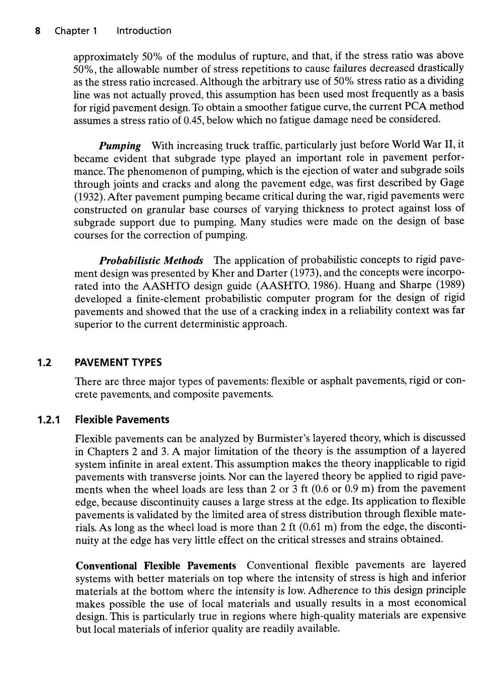
Figure 1 .3 shows the typical cross section for a full-depth asphalt pavement . The asphalt base course in the full-depth construction is the same as the binder course i n conventional pavement. As with conventional pavement, a tack coat must be applie d between two asphalt layers to bind them together.
FIGURE 1 . 3
Typical cross-section of a full-depth asphal t pavement (1 in. = 25.4 mm) .
Asphalt Surface t 2 to 4 in 2 to 20 in
Asphalt Base Prepared Subgrade
According to the Asphalt Institute (AI, 1987), full-depth asphalt pavements hav e the following advantages :
1. They have no permeable granular layers to entrap water and impair performance.
2. Time required for construction is reduced . On widening projects, where adjacent traffic flow must usually be maintained, full-depth asphalt can be especially advantageous.
3. When placed in a thick lift of 4 in . (102 mm) or more, construction seasons may be extended.
4. They provide and retain uniformity in the pavement structure .
5. They are less affected by moisture or frost.
6. According to limited studies, moisture contents do not build up in subgrades under full-depth asphalt pavement structures as they do under pavements with granular bases. Thus, there is little or no reduction in subgrade strength.
1 .2.2 Rigid Pavements
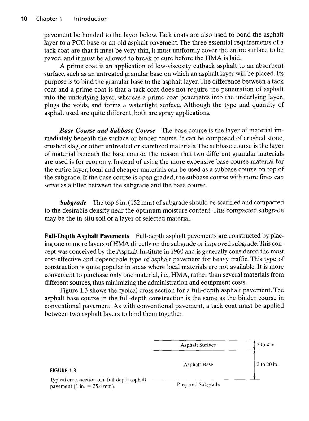
Rigid pavements are constructed of portland cement concrete and should be analyze d by the plate theory, instead of the layered theory. Plate theory is a simplified version of the layered theory that assumes the concrete slab to be a medium thick plate with a plane before bending which remains a plane after bending. If the wheel load is applied in the interior of a slab, either plate or layered theory can be used and both shoul d yield nearly the same flexural stress or strain, as discussed in Section 5 .3.4. If the wheel load is applied near to the slab edge, say less than 2 ft (0.61 m) from the edge, only the plate theory can be used for rigid pavements . The reason that the layered theory is applicable to flexible pavements but not to rigid pavements is that PCC is much stiffe r than HMA and distributes the load over a much wider area. Therefore, a distance of 2 ft (0.61 m) from the edge is considered quite far in a flexible pavement but not fa r enough in a rigid pavement. The existence of joints in rigid pavements also makes the layered theory inapplicable. Details of plate theory are presented in Chapters 4 and 5 Figure 1 .4 shows a typical cross section for rigid pavements . In contrast to flexible pavements, rigid pavements are placed either directly on the prepared subgrade or on a single layer of granular or stablized material . Because there is only one layer o f material under the concrete and above the subgrade, some call it a base course, other s a subbase.
Portland Cement Concrete
Base or Subbase Course May or May Not Be Used
FIGURE 1 . 4
Typical cross section of a rigid pavement (1 in . = 25.4 mm).
6—12 in 4—12 in
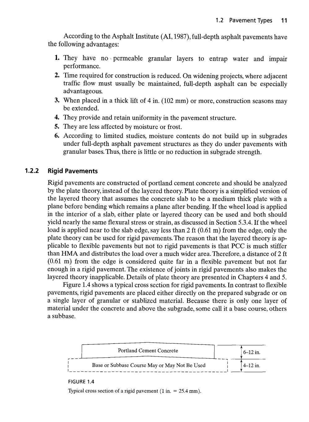
FIGURE 1 . 5
Pumping of rigid pavement
Use of Base Course Early concrete pavements were constructed directly on the subgrade without a base course. As the weight and volume of traffic increased, pumping began to occur, and the use of a granular base course became quite popular . When pavements are subject to a large number of very heavy wheel loads with free water on top of the base course, even granular materials can be eroded by the pulsative action o f water. For heavily traveled pavements, the use of a cement-treated or asphalt-treate d base course has now become a common practice .
Although the use of a base course can reduce the critical stress in the concrete, it is uneconomical to build a base course for the purpose of reducing the concrete stress Because the strength of concrete is much greater than that of the base course, the sam e critical stress in the concrete slab can be obtained without a base course by slightl y increasing the concrete thickness. The following reasons have been frequently cited fo r using a base course
Control of Pumping Pumping is defined as the ejection of water and subgrad e soil through joints and cracks and along the edges of pavements, caused by downwar d slab movements due to heavy axle loads. The sequence of events leading to pumping includes the creation of void space under the pavement caused by the temperatur e curling of the slab and the plastic deformation of the subgrade, the entrance of water , the ejection of muddy water, the enlargement of void space, and finally the faulting and cracking of the leading slab ahead of traffic. Pumping occurs under the leading slab when the trailing slab rebounds, which creates a vacuum and sucks the fine materia l from underneath the leading slab, as shown in Figure 1.5 . The corrective measures fo r pumping include joint sealing, undersealing with asphalt cements, and muck jackin g with soil cement.
Three factors must exist simultaneously to produce pumping :
1. The material under the concrete slab must be saturated with free water . If the material is well drained, no pumping will occur. Therefore, good drainage is one of the most efficient ways to prevent pumping.
2. There must be frequent passage of heavy wheel loads . Pumping will take place only under heavy wheel loads with large slab deflections. Even under very heavy loads, pumping will occur only after a large number of load repetitions
3. The material under the concrete slab must be erodible . The erodibility of a material depends on the hydrodynamic forces created by the dynamic action of moving
wheel loads. Any untreated granular materials, and even some weakly cemente d materials, are erodible because the large hydrodynamic pressure will transport the fine particles in the subbase or subgrade to the surface. These fine particles will go into suspension and cause pumping
Control of Frost Action
Frost action is detrimental to pavement performance. It results in frost heave, which causes concrete slabs to break and softens the subgrad e during the frost-melt period. In northern climates, frost heave can reach several inche s or more than one foot. The increase in volume of 9% when water becomes frozen i s not the real cause of frost heave. For example, if a soil has a porosity of 0 .5 and is subjected to a frost penetration of 3 ft (0.91 m), the amount of heave due to 9% increase in volume is 0.09 x 3 x 0.5 = 0.135 ft or 1.62 in. (41 mm), which is much smaller than the 6 in. (152 mm) or more of heave experienced in such climate
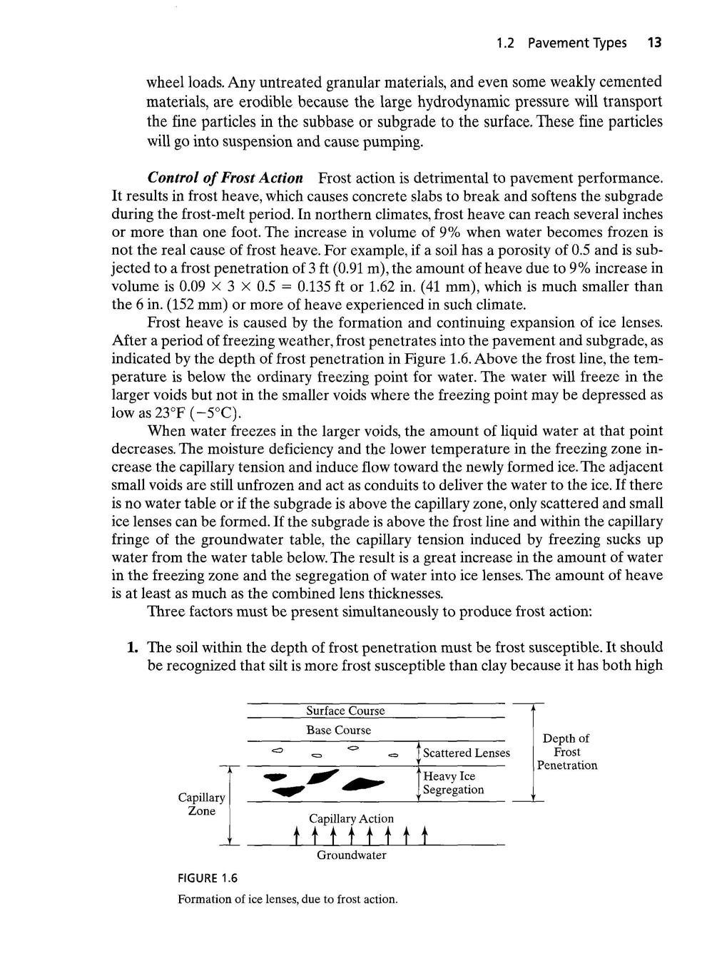
Frost heave is caused by the formation and continuing expansion of ice lenses. After a period of freezing weather, frost penetrates into the pavement and subgrade, a s indicated by the depth of frost penetration in Figure 1 .6. Above the frost line, the temperature is below the ordinary freezing point for water. The water will freeze in the larger voids but not in the smaller voids where the freezing point may be depressed as low as 23°F (-5°C) .
When water freezes in the larger voids, the amount of liquid water at that poin t decreases. The moisture deficiency and the lower temperature in the freezing zone increase the capillary tension and induce flow toward the newly formed ice . The adjacent small voids are still unfrozen and act as conduits to deliver the water to the ice . If there is no water table or if the subgrade is above the capillary zone, only scattered and small ice lenses can be formed. If the subgrade is above the frost line and within the capillary fringe of the groundwater table, the capillary tension induced by freezing sucks u p water from the water table below. The result is a great increase in the amount of water in the freezing zone and the segregation of water into ice lenses. The amount of heave is at least as much as the combined lens thicknesses
Three factors must be present simultaneously to produce frost action :
1. The soil within the depth of frost penetration must be frost susceptible . It should be recognized that silt is more frost susceptible than clay because it has both hig h
capillarity and high permeability. Although clay has a very high capillarity, its permeability is so low that very little water can be attracted from the water table to form ice lenses during the freezing period. Soils with more than 3% finer tha n 0.02 mm are generally frost susceptible, except that uniform fine sands with more than 10% finer than 0.02 mm are frost susceptible
2. There must be a supply of water. A high water table can provide a continuou s supply of water to the freezing zone by capillary action. Lowering the water table by subsurface drainage is an effective method to minimize frost action .
3. The temperature must remain freezing for a sufficient period of time . Due to the very low permeability of frost-susceptible soils, it takes time for the capillar y water to flow from the water table to the location where the ice lenses ar e formed. A quick freeze does not have sufficient time to form ice lenses of an y significant size
Improvement of Drainage When the water table is high and close to the ground surface, a base course can raise the pavement to a desirable elevation above th e water table. When water seeps through pavement cracks and joints, an open-graded base course can carry it away to the road side. Cedergren (1988) recommends the us e of an open-graded base course under every important pavement to provide an interna l drainage system capable of rapidly removing all water that enters .
Control of Shrinkage and Swell When moisture changes cause the subgrade t o shrink and swell, the base course can serve as a surcharge load to reduce the amount o f shrinkage and swell. A dense-graded or stabilized base course can serve as a waterproofing layer, and an open-graded base course can serve as a drainage layer. Thus, the reduction of water entering the subgrade further reduces the shrinkage and swel l potentials
Expedition of Construction A base course can be used as a working platfor m for heavy construction equipment . Under inclement weather conditions, a base course can keep the surface clean and dry and facilitate the construction work As can be seen from the above reasoning, there is always a necessity to build a base course. Consequently, base courses have been widely used for rigid pavements
Types of Concrete Pavement Concrete pavements can be classified into four types : jointed plain concrete pavement (JPCP), jointed reinforced concrete pavement (JRCP), continuous reinforced concrete pavement (CRCP), and prestressed concret e pavement (PCP). Except for PCP with lateral prestressing, a longitudinal joint shoul d be installed between two traffic lanes to prevent longitudinal cracking . Figure 1.7 shows the major characteristics of these four types of pavements .
Jointed Plain Concrete Pavements All plain concrete pavements should be constructed with closely spaced contraction joints . Dowels or aggregate interlocks may be used for load transfer across the joints. The practice of using or not using dowels varies among the states. Dowels are used most frequently in the southeastern states, aggregate interlocks in the western and southwestern states, and both are used in other