https://ebookmass.com/product/microprocessors-and-
Instant digital products (PDF, ePub, MOBI) ready for you
Download now and discover formats that fit your needs...
Digital Systems: Principles and Applications, 12th Edition
Ronald J. Tocci
https://ebookmass.com/product/digital-systems-principles-andapplications-12th-edition-ronald-j-tocci/
ebookmass.com
Code: The Hidden Language of Computer Hardware and Software 2nd Edition Charles Petzold
https://ebookmass.com/product/code-the-hidden-language-of-computerhardware-and-software-2nd-edition-charles-petzold/
ebookmass.com
Hardware and Software Projects Troubleshooting: How Effective Requirements Writing Can Save the Day, 2nd Edition George Koelsch
https://ebookmass.com/product/hardware-and-software-projectstroubleshooting-how-effective-requirements-writing-can-save-theday-2nd-edition-george-koelsch/ ebookmass.com
Basic geriatric nursing 6. ed Edition Williams
https://ebookmass.com/product/basic-geriatric-nursing-6-ed-editionwilliams/
ebookmass.com
Family Health Care Nursing: Theory, Practice, and Research
6th Edition
https://ebookmass.com/product/family-health-care-nursing-theorypractice-and-research-6th-edition/
ebookmass.com
A Little Risk: An MM Age Play Romance (Little Club New York City Book 4) Zack Wish
https://ebookmass.com/product/a-little-risk-an-mm-age-play-romancelittle-club-new-york-city-book-4-zack-wish/
ebookmass.com
Annuities For Dummies, 2nd Edition Kerry Pechter
https://ebookmass.com/product/annuities-for-dummies-2nd-edition-kerrypechter/
ebookmass.com
Indian Polity 5th Edition M Laxmikanth
https://ebookmass.com/product/indian-polity-5th-edition-m-laxmikanth/
ebookmass.com
One For My Enemy: A Bewitching Urban Fantasy from the Author of The Atlas Six Olivie Blake
https://ebookmass.com/product/one-for-my-enemy-a-bewitching-urbanfantasy-from-the-author-of-the-atlas-six-olivie-blake/
ebookmass.com
DreamWorks Animation: Intertextuality and Aesthetics in Shrek and Beyond 1st ed. Edition Sam Summers
https://ebookmass.com/product/dreamworks-animation-intertextualityand-aesthetics-in-shrek-and-beyond-1st-ed-edition-sam-summers/
ebookmass.com
Microprocessors and Microcomputers
Hardware and Software
Ronald J. Tocci
Monroe Community College
Frank J. Ambrosio
Monroe Community College
Lester P. Laskowski
University of Texas Medical Branch
PRENTICE HALL
Upper Saddle River; New Jersey
Columbus, Ohio
Library of Congress Cataloging-in-Publication Data
Tocci, Ronald J. Microprocessors and microcomputers : hardware and software I Ronald J. Tocci, Frank Ambrosio, Lester P. Laskowski.-4th ed. p. cm. Includes index. ISBN 0--13-235946-4
I. Microprocessors. 2. Microcomputers. I. Ambrosio, Frank. II. Laskowski, Lester P. Ill. Title. QA76.5.T556 1997 004. I 6-dc20
96-23742 CIP
Editor: Charles E. Stewart, Jr.
Production Editor: Mary Harlan
Production Coordination: WordCrafters Editorial Services, Inc.
Designer: Linda Zuk
Cover Designer: Rod Harris
Production Manager: Patricia A. Tonneman
Marketing Manager: Debbie Yarnell
Illustrations: Diphrent Strokes
Cover photo: Superstock
This book was set in Times Roman by The Clarinda Company and was printed and bound by R.R. Donnelley & Sons Company. The cover was printed by Phoenix Color Corp.
© 1997, 1987, 1982, 1979 by Prentice-Hall, Inc. Simon & Schuster/A Viacom Company Upper Saddle River, New Jersey 07458
All rights reserved. No part of this book may be reproduced, in any form or by any means, without permission in writing from the publisher.
Printed in the United States of America
10 9 8 7 6 5 4 3 2
ISBN 0-13-235946-4
Prentice-Hall International (UK) Limited, London
Prentice-Hall of Australia Pty. Limited, Sydney
Prentice-Hall Canada Inc., Toronto
Prentice-Hall Hispanoamericana, S.A., Mexico
Prentice-Hall of India Private Limited, New Delhi
Prentice-Hall of Japan, Inc., Tokyo
Simon & Schuster Asia Pte. Ltd., Singapore
Editora Prentice-Hall do Brasil, Ltda., Rio de Janeiro
Preface
This book was written to provide a comprehensible introduction to microprocessors and microcomputers for a broad range of readers. It can serve as a textbook in electronic technology, computer technology, and computer science programs from the vocational school to four-year college level. It can also be used by computer hobbyists as well as practicing technicians and engineers. A significant portion of the text requires a basic knowledge of digital principles and circuits. For this reason, a comprehensive review of this material is presented in the first three chapters to help those readers who have only a minimal background or who have been away from the field for a while.
The major philosophy that has been followed in this book is that the principles and techniques of microprocessors and microprocessor-based systems are the most important concepts to understand, and it is not necessary to survey the whole field of available microprocessors and microprocessor applications. We believe that the best pedagogical approach is to use a currently popular, powerful, yet easy-to-understand microprocessor chip as the vehicle for teaching these concepts. We also believe that since 8-bit microprocessors are simple and easy to understand, this makes them an appropriate choice for an introductory textbook. As such, for this new edition we have chosen to use the 68HC11 microprocessor as that vehicle (replacing the obsolete 6502 of the earlier editions). The 68HC1 l is one of the most powerful and flexible 8-bit microprocessors in general use, and it contains all of the elements and features that need to be part of an introduction to microprocessors and microprocessor applications. Everything the reader learns and understands using this representative device can be readily transferred to other microprocessors and applications, including the more complex 16-bit and 32-bit devices.
This fourth edition retains all of the valuable learning aids of the previous editions, including ( l) extensive use of clearly explained illustrative examples to provide immediate reinforcement; (2) clear, uncluttered diagrams to enhance the understanding of the written material; (3) liberal use of flowcharts; (4) glossaries of important terms at the end of each chapter for easy review of chapter contents; (5) more than 400 end-of-chapter questions and problems of varied complexity; and (6) an extensive appendix containing a detailed description of each of the 68HC 11 's available instructions.
This edition represents an extensive updating and revision of the last edition. The 68HC11 is used as the representative microprocessor in all presentations, discussions, examples, and applications. In addition to this major change, there are other substantial improvements. Here is the list by chapter.
All Chapters. Addition of instructional objectives.
Chapter 1. Addition of topics of negation and overflow.
Chapter 2. Considerable expansion of data bus concepts and operation.
Chapter 3. Expansion and updating of all memory types. Addition of flash memory. Increased coverage of DRAM operation and refreshing.
Chapter 4. Addition of topics of microprogramming, microcontrollers, and assemblers.
Chapter 5. Addition of material on reset operation, on-chip memory and 1/0 ports, and 4K pages.
Chapter 6. Expansion of two-operand ALU operations. Addition of material on MPU reset operation including Computer Operating Properly (COP) Reset and Clock Monitor Reset.
Chapter 7. Addition of multiplication and division instructions. Addition of on-chip timer system. Expansion of programmed time intervals.
Chapter 8. Inclusion of on-chip AID converter system. Addition of wide range of on-chip control registers.
Chapter 9. Expansion of material on Baud rate, synchronous communication, RS232-C standard, and modems. Addition of material on 68HC1 l's onchip serial communication system, and on the Centronics printer interface.
We wish to thank those who reviewed the manuscript for this edition: Howard Atwell, Fullerton College; Phillipe Cauvet, Bramson O RT Technical Institute; Donald C. Davis, ITT Technical Institute; James C. Graves, Jr., Indian River Community College; Shahram Latifi, University of Nevada; and Mohammad Dabbas, ITT Technical Institute. We are also grateful for the valuable comments and suggestions from users of previous editions. Many of these contributions have been incorporated into this revision. We hope that this new edition with its updating and improvements and its new microprocessor has retained the same style, approach, and clarity that has made previous editions so well accepted by instructors, students, and other users.
Contents
1 NUMBER SYSTEMS AND CODES
1.1 Digital Number Systems, 2
1.2 Codes, 10
1.3 Binary Arithmetic, 14
1.4 Addition Using Signed Numbers, 18
1.5 Subtraction in the 2's-Complement System, 20
1.6 Multiplication of Binary Numbers, 21
1.7 Binary Division, 22
1.8 Hexadecimal Arithmetic, 23
2 DIGITAL CIRCUITS 28
2.1 Parallel and Serial Transmission, 29
2.2 Logic Gates, 30
2.3 Tri-State (Three-State) Logic, 32
2.4 Flip-Flops, 33
2.5 Clock Signals, 34
2.6 Clocked Flip-Flops, 36
2.7 Synchronous and Asynchronous FF Inputs, 38
2.8 Setup and Hold Times, 39
2.9 FF Registers, 40
2.10 IC Registers, 42
2.11 Data Busing, 45
2.12 Data Bus Operation, 46
2.13 Decoders, 54
2.14 Encoders, 56
2.15 Multiplexers (Data Selectors), 57
2.16 Arithmetic Circuits, 58
3 MEMORY DEVICES 63
3.1 Memory Terminology, 65
3.2 General Memory Operation, 67
3.3 Read Only Memories, 69
3.4 ROM Architecture, 71
3.5 ROM Timing, 73
3.6 Types of ROM, 74
3.7 Flash Memory, 82
3.8 ROM Applications, 86
3.9 Semiconductor RAMs, 89
3. IO RAM Architecture, 89
3.11 Static RAM, 92
3.12 Dynamic RAM, 95
3. I 3 Dynamic RAM Structure and Operation, 96
3.14 DRAM READ/WRITE Cycles, 101
3.15 DRAM Refreshing, 104
3.16 Expanding Word Size and Capacity, 105
4 INTRODUCTION TO COMPUTERS 1 19
4.1 What Can Computers Do?, 120
4.2 How Do Computers Think?, 122
4.3 How Many Kinds of Computers Are There?, 124
4.4 Basic Computer Structure, 125
4.5 Microprocessors, 129
4.6 Computer Words, 129
4.7 Binary Data Words, 129
4.8 Coded Data Words, 131
4.9 Instruction Words, 132
4.10 The 68HC11 MPU-A Simplified Version, 137
4.11 Executing a Program, 141
4.12 Jump and Branch Instructions, 145
4.13 Hardware, Software, and Firmware, 148
4.14 Programming Languages-Machine Language, 148
4.15 Assembly Language, 150
4.16 High-Level Languages, 152
4.17 Flowcharts, 154
5 MICROCOMPUTER STRUCTURE AND OPERATION 164
5.1 Microcomputer Elements, 165
5.2 Why µPs and µCs?, 166
5.3 Microcomputer Architecture, 168
5.4 READ and WRITE Timing, 174
5.5 Bus Activity During Program Execution, 178
5.6 MPU Address Space Allocation, 182 CONTENTS
5.7 Memory Modules, 187
5.8 Address Decoding, 187
5.9 Complete Microcomputer Decoding Example, 189
5.10 Buffering the MPU Buses, 199
5.11 Memory-Mapped and Isolated VO, 200
6 THE MICROPROCESSOR: HEART OF THE MICROCOMPUTER 209
6.1 68HC 11 MPU-More Complete Version, 210
6.2 Timing and Control Section, 212
6.3 Register Section, 215
6.4 Arithmetic/Logic Unit, 227
6.5 Microprocessors-Categorized by ALU Size, 233
6.6 Microprocessors-Two Directions, 234
7 PROGRAMMING THE 68HC 1 1 MPU 242
7.1 68HC1 l MPU Programming Model, 243
7.2 68HC11 MPU Address Modes, 247
7.3 The 68HC11 MPU Instruction Set, 255
7.4 Instruction Descriptions, 257
7 .5 Program Listing Format, 259
7.6 Instruction Classifications, 260
7. 7 CCR Instructions, 262
7.8 Register-to-Memory Transfer Instructions, 262
7.9 Register-to-Register Transfer Instructions, 264
7 .10 Arithmetic Instructions, 266
7.11 Logical Instructions, 276
7 .12 Shift and Rotate Instructions, 280
7.13 Data-Altering Instructions, 285
7.14 Jump Instructions, 289
7.15 Conditional Branching, 290
7 .16 68HC 11 Conditional Branch Instructions, 295
7 .17 Compare Instructions, 302
7 .18 BIT and TST Instructions, 306
7 .19 Subroutines, 308
7 .20 Interrupt Handling Instructions, 311
7.21 Applications Using Indexed Addressing, 312
7 .22 The No-Operation (NOP) and STOP Instructions, 316
7.23 Program-Controlled Timing Intervals (Delays), 318
7.24 Time-Delay Subroutines, 324
7.25 The Timer System of the 68HC11 MCU, 328
7.26 The Software Development Process, 333
CONTENTS
8 INPUT/OUTPUT MODES 353
8.1 Some Basic Terms, 354
8.2 Some Examples of 1/0, 354
8.3 Input/Output Alternatives, 356
8.4 MPV-Initiated-Unconditional 1/0 Transfer, 357
8.5 MPV-Initiated-Conditional (Polled) 1/0 Transfer, 361
8.6 The 68HC11 MCU Block Diagram, 366
8. 7 Port E of the 68HC 11 MCU-A/D Converter, 368
8.8 Device-Initiated 1/0 Transfer-Interrupts, 374
8.9 Return Address, 375
8.10 Disabling the Interrupt, 377
8.11 Types of Interrupt Inputs, 378
8.12 Address of an JSR-Interrupt Vectors, 382
8.13 Interrupting an ISR, 384
8.14 Multiple Interrupts, 386
8.15 Port A of the 68HC11 MCU, 390
8.16 Direct Memory Access (DMA 1/0 Transfer, 403
9 INPUT/OUTPUT INTERFACING 414
9 .1 Practical Interface Considerations, 415
9.2 Asynchronous Serial Data Communication, 421
9.3 Parallel/Serial Interface-The UART, 425
9.4 Motorola 6850 UART (ACIA), 429
9.5 Interfacing the 6850 to the 68HC11 MPU, 434
9.6 Port D of the 68HC11 MCU-Serial Communications Interface (SCI), 441
9.7 Synchronous Serial Data Communication, 450
9.8 EIA RS-232-C Standard, 452
9.9 Introduction to Modems, 453
9.10 Parallel 1/0 Interface Chips, 458
9.11 Keyboard Input Devices, 463
9.12 Video Display Terminals (VDTs), 470
APPENDIX A COMPLETE 68HC 11 MCU INSTRUCTION SET 486
APPENDIX B THE 68HC 11 MCU BLOCK DIAGRAM 541
APPENDIX C THE 68HC 11 MCU REGISTER AND CONTROL BIT ASSIGNMENTS 543
ANSWERS TO SELECTED PROBLEMS 546
INDEX 551
1. 1 DIGITAL NUMBER SYSTEMS
Although actual computer operations use the binary number system, several other number systems are used to communicate with computers. The most common are the decimal, octal, and hexadecimal systems.
Decimal System
The decimal system is composed of the 10 symbols or digits: 0, 1, 2, 3, 4, 5, 6, 7, 8, and 9; using these symbols, we can express any quantity. The decimal system, also called the base 10 system, because it has 10 digits, has evolved naturally as a result of the fact that human beings have 10 fingers. In fact, the word "digit" is the Latin word for "finger."
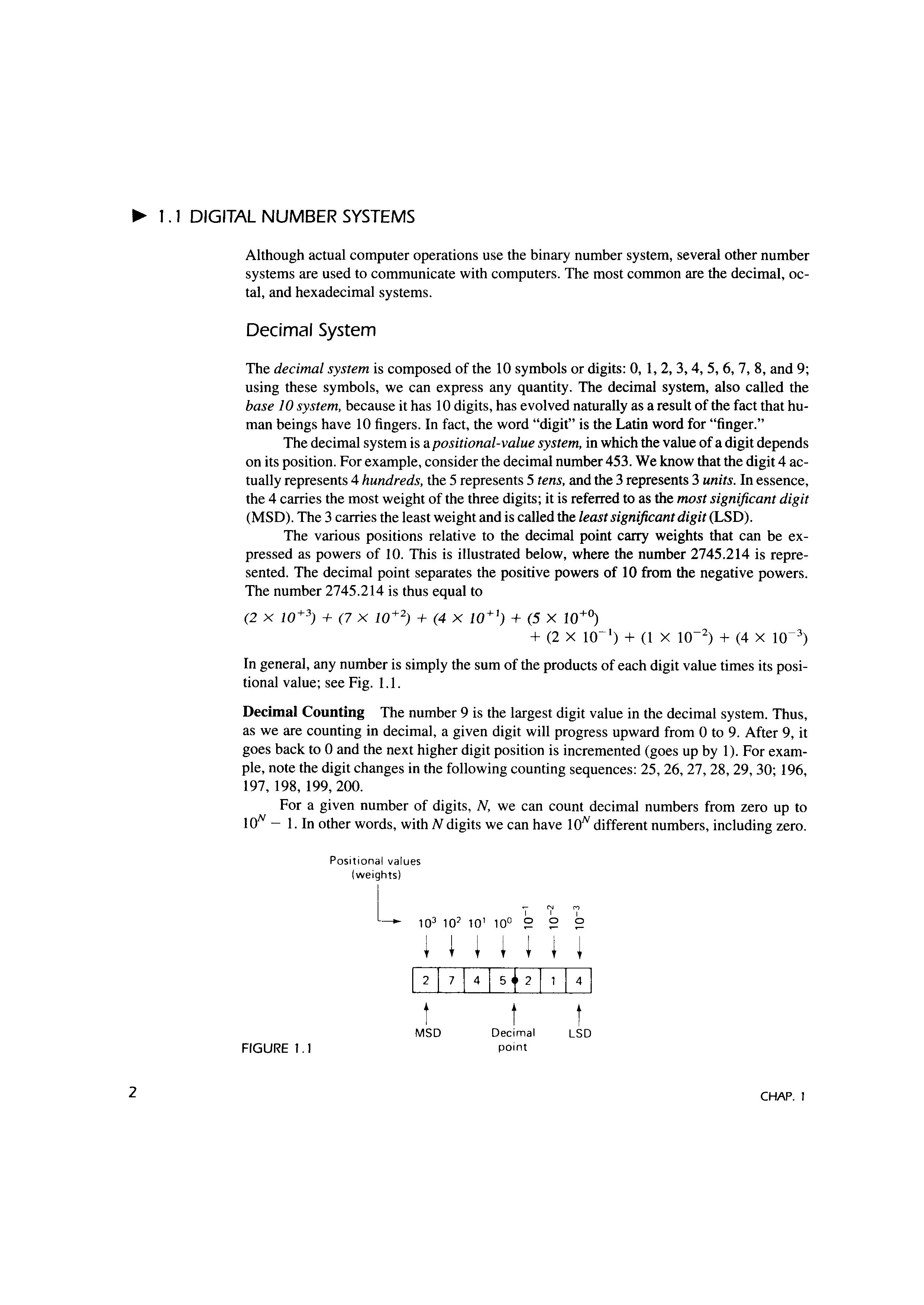
The decimal system is a positional-value system, in which the value of a digit depends on its position. For example, consider the decimal number 453. We know that the digit 4 actually represents 4 hundreds, the 5 represents 5 tens, and the 3 represents 3 units. In essence, the 4 carries the most weight of the three digits; it is referred to as the most significant digit (MSD). The 3 carries the least weight and is called the least significant digit (LSD).
The various positions relative to the decimal point carry weights that can be expressed as powers of 10. This is illustrated below, where the number 2745.214 is represented. The decimal point separates the positive powers of 10 from the negative powers. The number 2745.214 is thus equal to (2 x 10+ 3) + (7 x 10+ 2) + (4 x 10+ 1) + (5 x 10+ 0) + (2 x 10- 1) + (1 x 10- 2 ) + (4 x 10- 3 )
In general, any number is simply the sum of the products of each digit value times its positional value; see Fig. 1.1.
Decimal Counting
The number 9 is the largest digit value in the decimal system. Thus, as we are counting in decimal, a given digit will progress upward from Oto 9. After 9, it goes back to O and the next higher digit position is incremented (goes up by 1). For example, note the digit changes in the following counting sequences: 25, 26, 27, 28, 29, 30; 196, 197, 198, 199, 200.
For a given number of digits, N, we can count decimal numbers from zero up to 1ON - 1. In other words, with N digits we can have 1ON different numbers, including zero.
Positional values !weights)
FIGURE 1.1
CHAP.
FIGURE 1.2 point
To illustrate, with three decimal digits, we can count from 000 to 999, a total of 1000 different numbers.
Binary System
In the binary system there are only two symbols or possible digit values, 0 and 1. Even so, this base 2 system can be used to represent any quantity that can be represented in decimal or other number systems. In general, though, it will take a greater number of binary digits to express a given quantity.
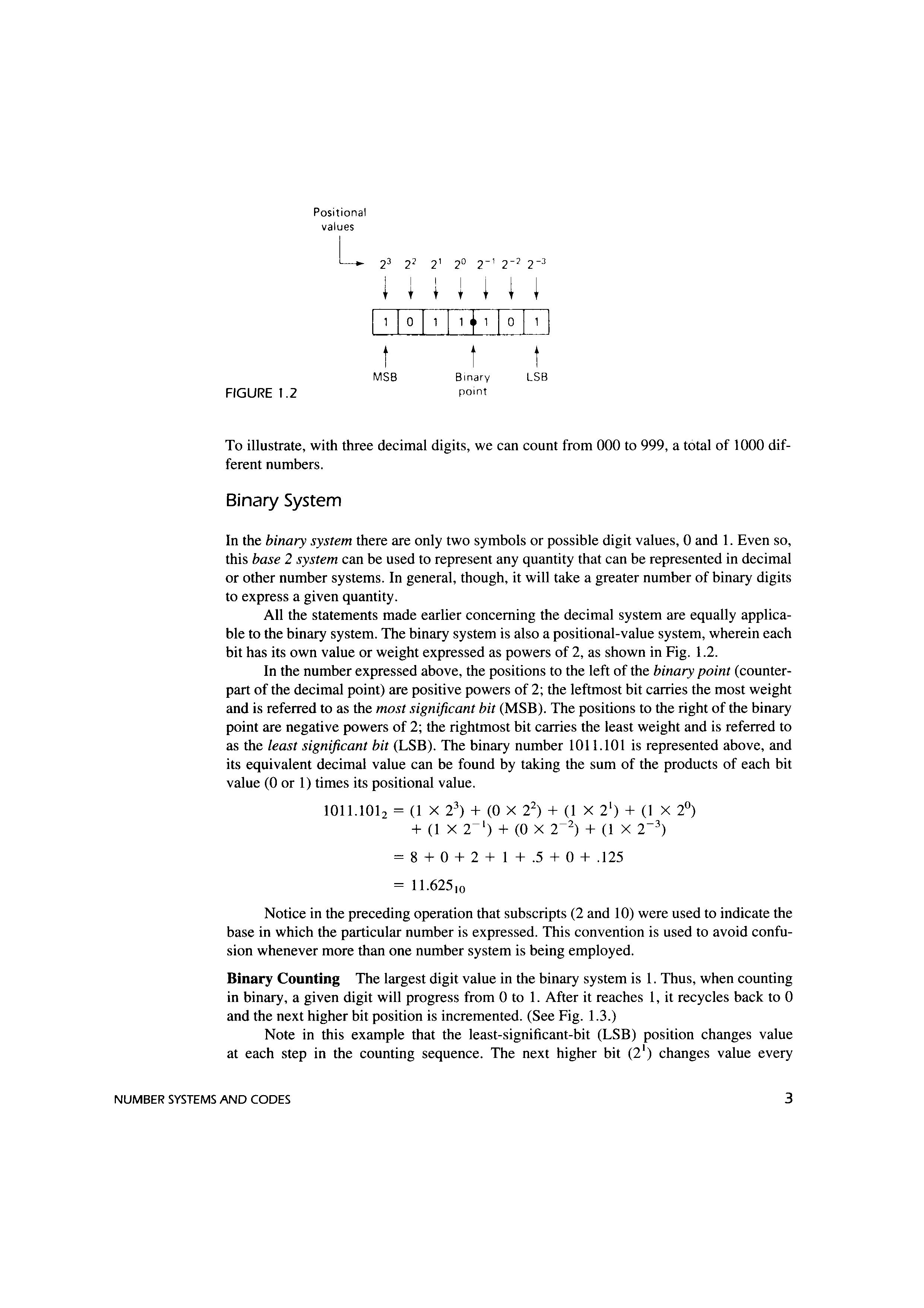
All the statements made earlier concerning the decimal system are equally applicable to the binary system. The binary system is also a positional-value system, wherein each bit has its own value or weight expressed as powers of 2, as shown in Fig. 1.2.
In the number expressed above, the positions to the left of the binary point (counterpart of the decimal point) are positive powers of 2; the leftmost bit carries the most weight and is referred to as the most significant bit (MSB). The positions to the right of the binary point are negative powers of 2; the rightmost bit carries the least weight and is referred to as the least significant bit (LSB). The binary number 1011.101 is represented above, and its equivalent decimal value can be found by taking the sum of the products of each bit value (0 or 1) times its positional value.
1011.1012 = (1 x 23 ) + (0 x 22) + (1 xi)+ (1 x 2°) + (1 X T 1 ) + (0 X T 2 ) + (1 x T 3 ) = 8 + 0 + 2 + 1 + .5 + 0 + .125 = 11.62510
Notice in the preceding operation that subscripts (2 and 10) were used to indicate the base in which the particular number is expressed. This convention is used to avoid confusion whenever more than one number system is being employed.
Binary Counting
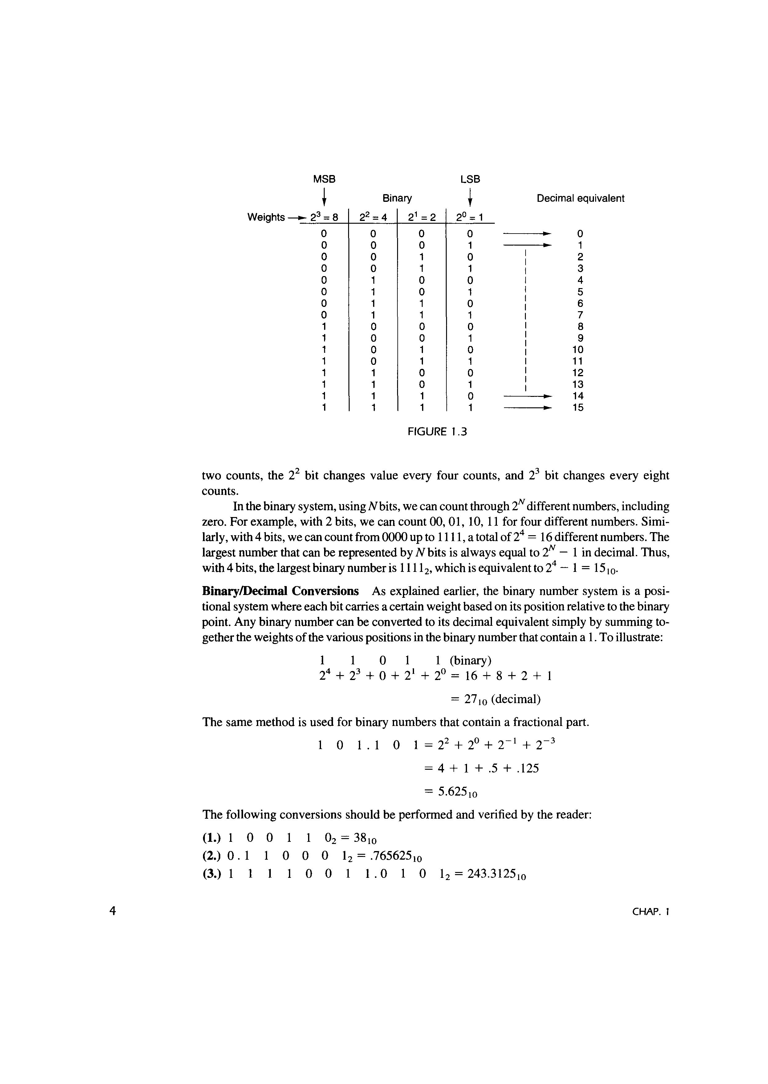
The largest digit value in the binary system is 1. Thus, when counting in binary, a given digit will progress from Oto 1. After it reaches 1, it recycles back to O and the next higher bit position is incremented. (See Fig. 1.3.)
Note in this example that the least-significant-bit (LSB) position changes value at each step in the counting sequence. The next higher bit (2 1 ) changes value every
two counts, the 22 bit changes value every four counts, and 23 bit changes every eight counts.
In the binary system, using Nbits, we can count through 2N different numbers, including zero. For example, with 2 bits, we can count 00, 01, 10, 11 for four different numbers. Similarly, with 4 bits, we can count from 0000 up to 1111, a total of 24 = 16 different numbers. The largest number that can be represented by Nbits is always equal to 2N - 1 in decimal. Thus, with 4 bits, the largest binary number is 1111 2, which is equivalent to 24 - 1 = 15 10
Binary/Decimal Conversions As explained earlier, the binary number system is a positional system where each bit carries a certain weight based on its position relative to the binary point. Any binary number can be converted to its decimal equivalent simply by summing together the weights of the various positions in the binary number that contain a 1. To illustrate:
1 1 0 1 1 (binary) 24 + 23 + 0 + 2 1 + 2° = 16 + 8 + 2 + 1
= 27 10 (decimal)
The same method is used for binary numbers that contain a fractional part. 0 1 . 1 0 1 = 22 + 2° + T 1 + T 3
= 4 + 1 + .5 + .125
= 5.62510
The following conversions should be performed and verified by the reader:
FIGURE 1.3
CHAP.
There are several ways to convert a decimal number to its equivalent binary system representation. A method that is convenient for small numbers is just the reverse of the process described in the preceding section. The decimal number is simply expressed as a sum of powers of 2 and then 1sand Os are written in the appropriate bit positions. To illustrate:
Another example:
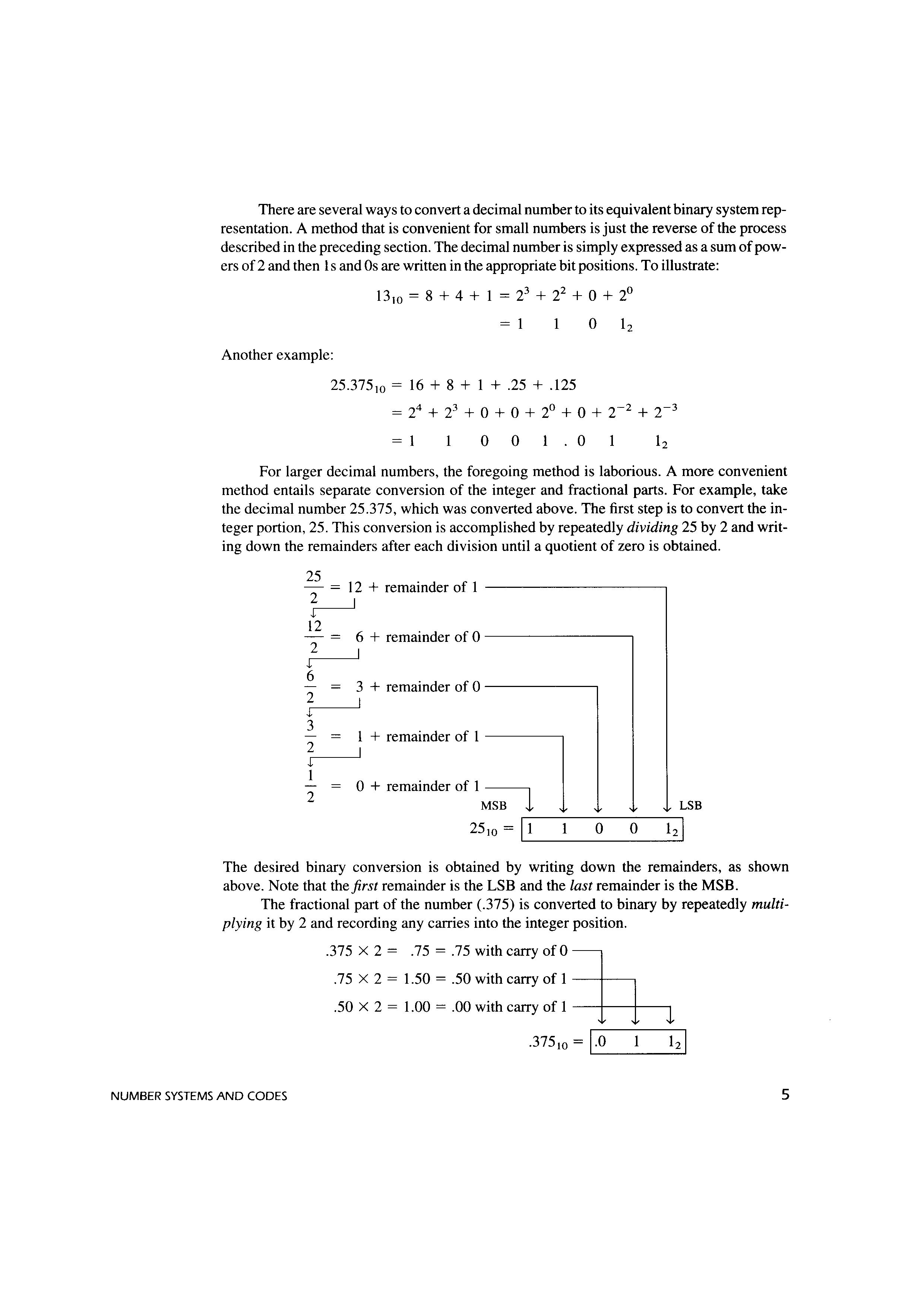
For larger decimal numbers, the foregoing method is laborious. A more convenient method entails separate conversion of the integer and fractional parts. For example, take the decimal number 25.375, which was converted above. The first step is to convert the integer portion, 25. This conversion is accomplished by repeatedly dividing 25 by 2 and writing down the remainders after each division until a quotient of zero is obtained.
The desired binary conversion is obtained by writing down the remainders, as shown above. Note that the first remainder is the LSB and the last remainder is the MSB. The fractional part of the number (.375) is converted to binary by repeatedly multiplying it by 2 and recording any carries into the integer position
375 X 2 = .75 = .75 with carry ofO
.75 X 2 = 1.50 = .50 with carry of 1 .50 X 2 = 1.00 = .00 with carry of 1
Note that the repeated multiplications continue until a product of 1.00 is reached,* since any further multiplications result in all zeros. Notice here that the first carry is written in the first position to the right of the binary point.
Finally, the complete conversion for 25.375 can be written as the combination of the integer and fraction conversions.
25.375!0 = 1 0 0 1 . 0
The reader should apply this method to verify the following conversion:
632.85 10 = 1 0 0 0 0 0 0
Octal Number System
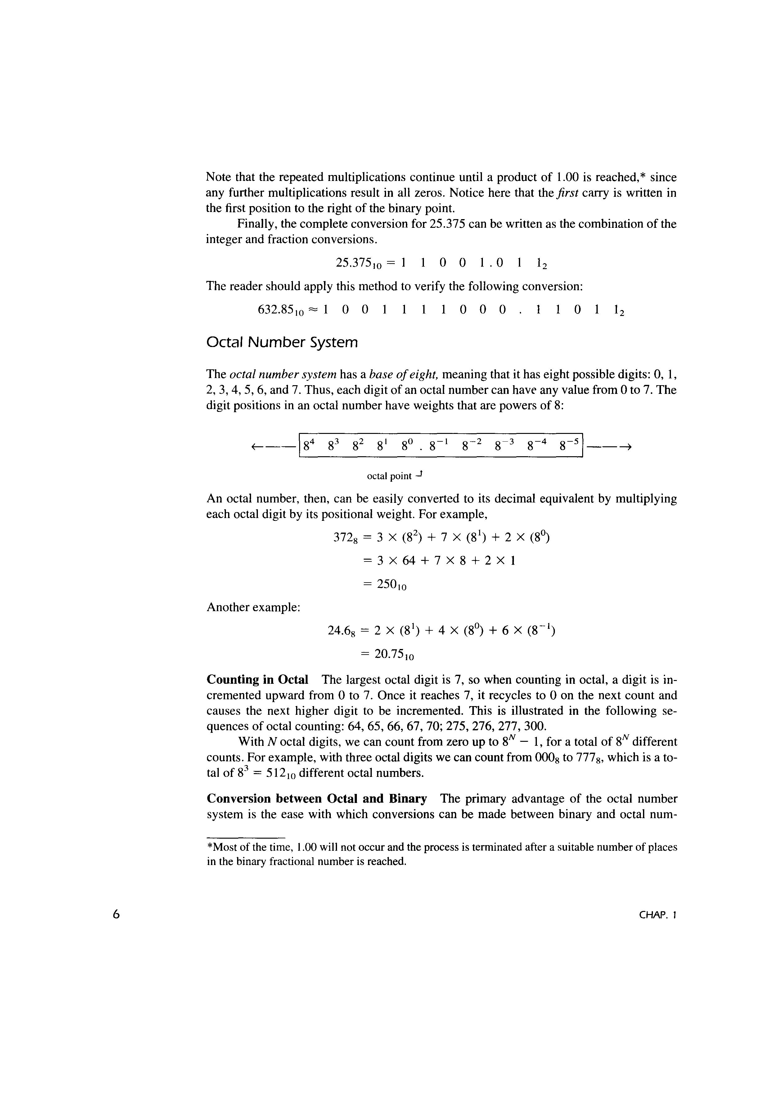
The octal number system has a base of eight, meaning that it has eight possible digits: 0, 1, 2, 3, 4, 5, 6, and 7. Thus, each digit of an octal number can have any value from Oto 7. The digit positions in an octal number have weights that are powers of 8:
octal point .J
An octal number, then, can be easily converted to its decimal equivalent by multiplying each octal digit by its positional weight. For example,
372g = 3 x (8 2 ) + 7 x (8 1 ) + 2 x (8°)
=3X64+7X8+2X]
= 250!0
Another example:
24.68 = 2 x (8 1 ) + 4 x (8°) + 6 x (8- 1 ) = 20.75!0
Counting in Octal The largest octal digit is 7, so when counting in octal, a digit is incremented upward from Oto 7. Once it reaches 7, it recycles to O on the next count and causes the next higher digit to be incremented. This is illustrated in the following sequences of octal counting: 64, 65, 66, 67, 70; 275, 276, 277, 300.
With N octal digits, we can count from zero up to 8N - 1, for a total of 8N different counts. For example, with three octal digits we can count from 0008 to 777 8 , which is a total of 83 = 512w different octal numbers.
Conversion between Octal and Binary The primary advantage of the octal number system is the ease with which conversions can be made between binary and octal num-
*Most of the time, 1.00 will not occur and the process is terminated after a suitable number of places in the binary fractional number is reached.
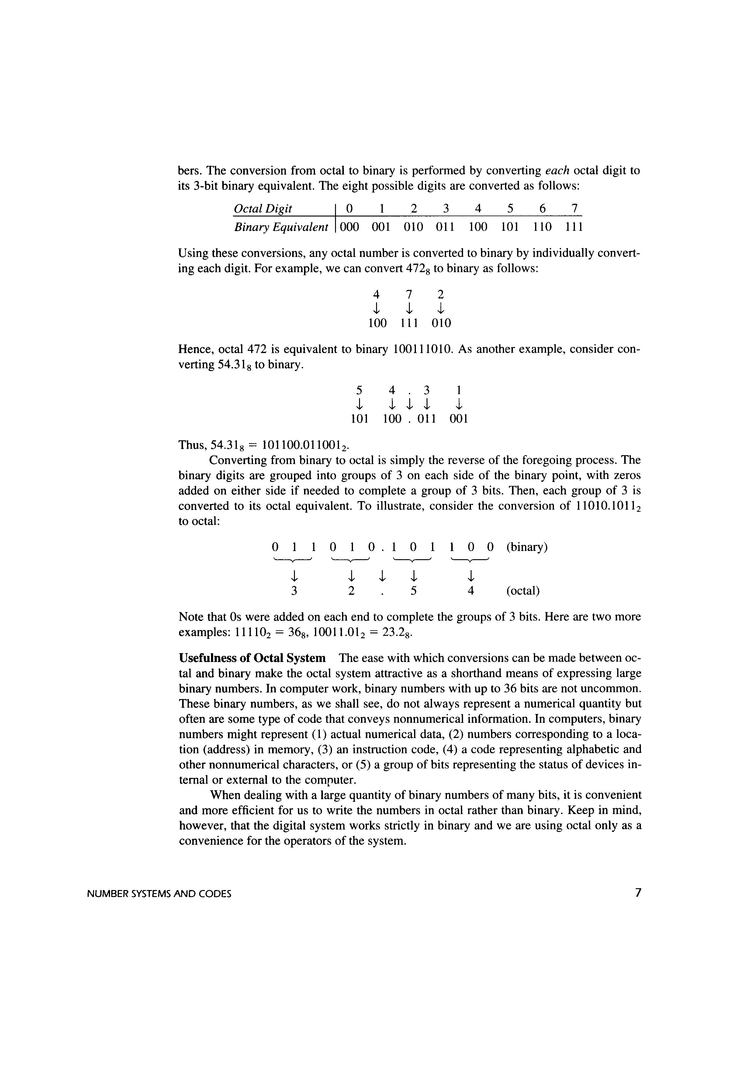
bers. The conversion from octal to binary is performed by converting each octal digit to its 3-bit binary equivalent. The eight possible digits are converted as follows:
Octal Digit O 2 3 4 5 6 7 Binary Equivalent 000 00 l 010 01 l 100 IOI 110 111
Using these conversions, any octal number is converted to binary by individually converting each digit. For example, we can convert 472 8 to binary as follows:
4 7 2 J, J, J, 100 111 010
Hence, octal 472 is equivalent to binary lOOl l lOIO. As another example, consider converting 54.31 8 to binary.
5 4 3 1 J, J, J, J, J, 101 100 . 011 001
Thus, 54.31 8 = lOl l00.011001 2
Converting from binary to octal is simply the reverse of the foregoing process. The binary digits are grouped into groups of 3 on each side of the binary point, with zeros added on either side if needed to complete a group of 3 bits. Then, each group of 3 is converted to its octal equivalent. To illustrate, consider the conversion of l lOI0.1011 2 to octal:
Note that Os were added on each end to complete the groups of 3 bits. Here are two more examples: 111102 = 368 , 10011.01 2 = 23.2 8
Usefulness of Octal System The ease with which conversions can be made between octal and binary make the octal system attractive as a shorthand means of expressing large binary numbers. In computer work, binary numbers with up to 36 bits are not uncommon. These binary numbers, as we shall see, do not always represent a numerical quantity but often are some type of code that conveys nonnumerical information. In computers, binary numbers might represent (1) actual numerical data, (2) numbers corresponding to a location (address) in memory, (3) an instruction code, (4) a code representing alphabetic and other nonnumerical characters, or (5) a group of bits representing the status of devices internal or external to the computer.
When dealing with a large quantity of binary numbers of many bits, it is convenient and more efficient for us to write the numbers in octal rather than binary. Keep in mind, however, that the digital system works strictly in binary and we are using octal only as a convenience for the operators of the system.
TABLE I. I
Hexadecimal (Hex) Decimal Binary
Hexadecimal Number System
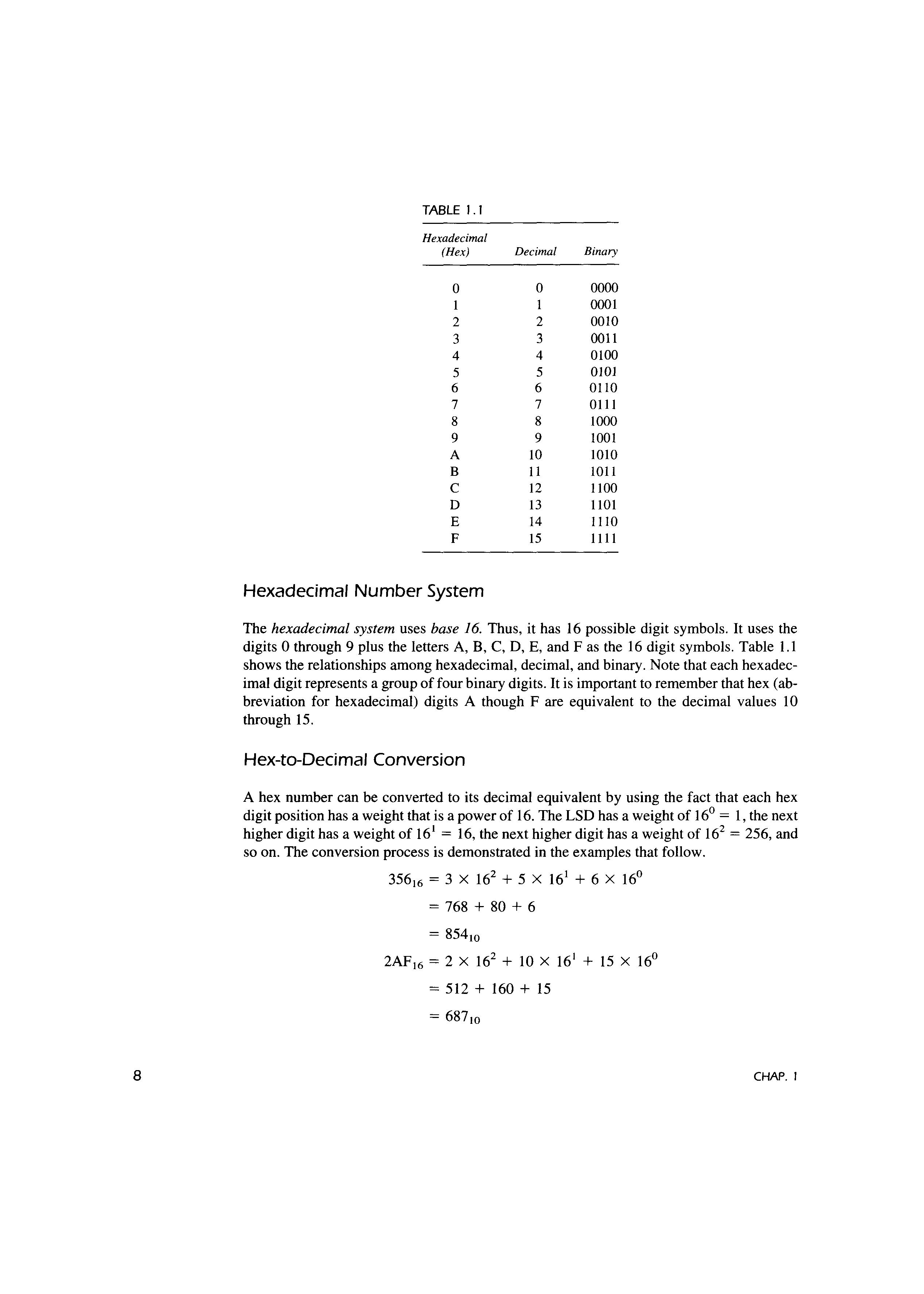
The hexadecimal system uses base 16. Thus, it has 16 possible digit symbols. It uses the digits O through 9 plus the letters A, B, C, D, E, and Fas the 16 digit symbols. Table 1.1 shows the relationships among hexadecimal, decimal, and binary. Note that each hexadecimal digit represents a group of four binary digits. It is important to remember that hex (abbreviation for hexadecimal) digits A though F are equivalent to the decimal values 10 through 15.
Hex-to-Decimal Conversion
A hex number can be converted to its decimal equivalent by using the fact that each hex digit position has a weight that is a power of 16. The LSD has a weight of I 6° = 1, the next higher digit has a weight of 16 1 = 16, the next higher digit has a weight of 162 = 256, and so on. The conversion process is demonstrated in the examples that follow.
35616 = 3 x 162 + 5 x 16 1 + 6 x 16° = 768 + 80 + 6 = 85410
2AF 16 = 2 X 16 2 + 10 X 16 1 + 15 X 16° = 512 + 160 + 15 = 68710
EXAMPLE I. I
Note that in the second example, the value 10 was substituted for A and the value 15 for F in the conversion to decimal.
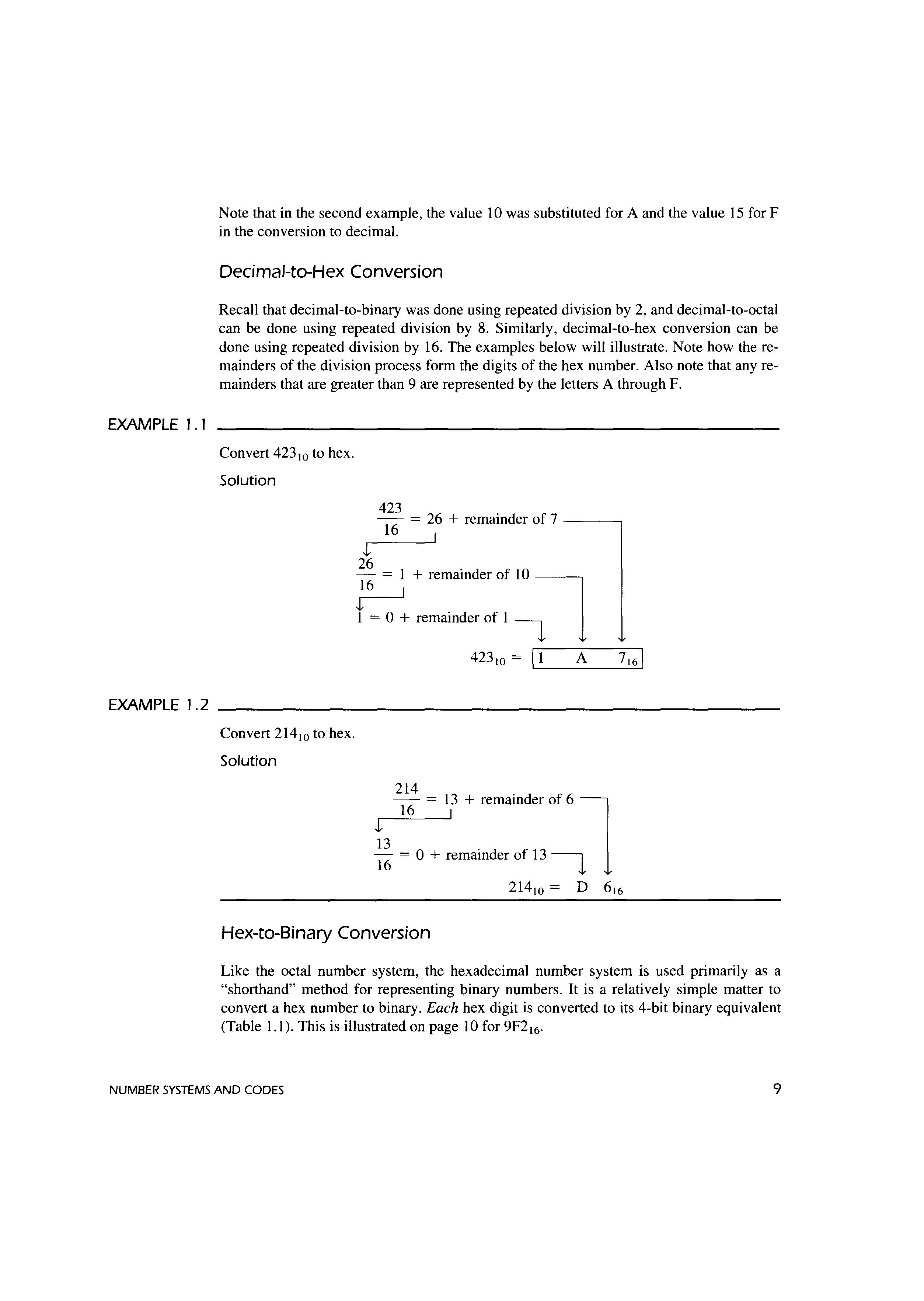
Decimal-to-Hex Conversion
Recall that decimal-to-binary was done using repeated division by 2, and decimal-to-octal can be done using repeated division by 8. Similarly, decimal-to-hex conversion can be done using repeated division by 16. The examples below will illustrate. Note how the remainders of the division process form the digits of the hex number. Also note that any remainders that are greater than 9 are represented by the letters A through F.
Convert 423 w to hex.
Solution
EXAMPLE 1.2
Convert 214w to hex.
Solution J 26 423 = 26 + remainder of 7 16 I
+ remainder of 10 1 1 = 0 + remainder of 1 -i 1 J 13 214 16
423 w = ir-1--A--7-1-,6I 13 + remainder of 6 I 16 = 0 + remainder of 13 t
214w = D 616
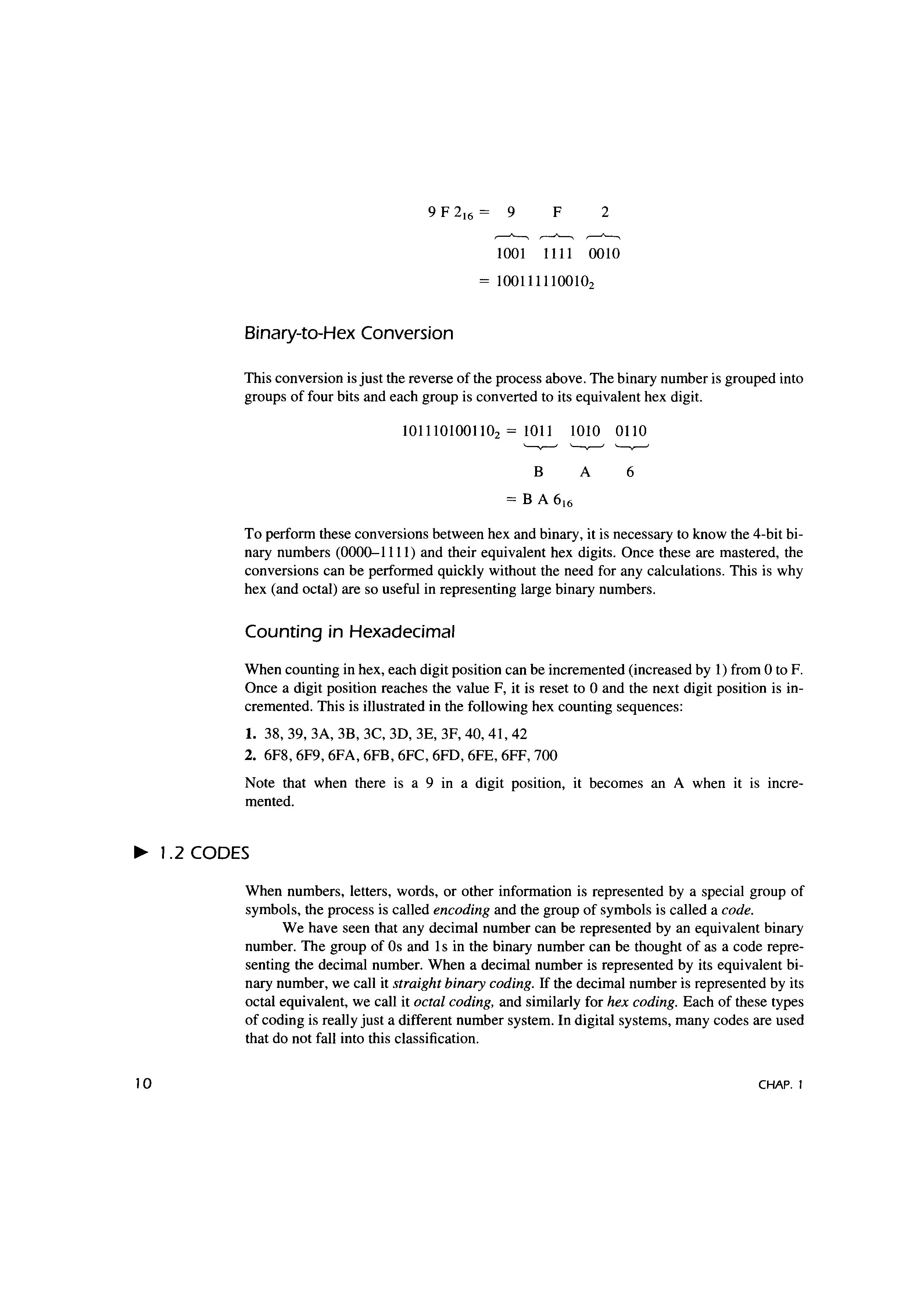
Hex-to-Binary Conversion
Like the octal number system, the hexadecimal number system is used primarily as a "shorthand" method for representing binary numbers. It is a relatively simple matter to convert a hex number to binary. Each hex digit is converted to its 4-bit binary equivalent (Table 1.1 ). This is illustrated on page 10 for 9F2 16 .
9 F 2 16 = 9 F 2
,-----"----, ,-----"----, ,-----"----, 1001 1111 0010
1001111100102
Binary-to-Hex Conversion
This conversion is just the reverse of the process above. The binary number is grouped into groups of four bits and each group is converted to its equivalent hex digit.
1011101001102 = 1011 1010 0110
B A 6
To perform these conversions between hex and binary, it is necessary to know the 4-bit binary numbers (0000-1111) and their equivalent hex digits. Once these are mastered, the conversions can be performed quickly without the need for any calculations. This is why hex (and octal) are so useful in representing large binary numbers.
Counting in Hexadecimal
When counting in hex, each digit position can be incremented (increased by 1) from Oto F. Once a digit position reaches the value F, it is reset to O and the next digit position is incremented. This is illustrated in the following hex counting sequences:
1. 38, 39, 3A, 38, 3C, 3D, 3E, 3F, 40, 41, 42
2. 6F8, 6F9, 6FA, 6FB, 6FC, 6FD, 6FE, 6FF, 700
Note that when there is a 9 in a digit position, it becomes an A when it is incremented.
1.2 CODES
When numbers, letters, words, or other information is represented by a special group of symbols, the process is called encoding and the group of symbols is called a code.
We have seen that any decimal number can be represented by an equivalent binary number. The group of Os and 1s in the binary number can be thought of as a code representing the decimal number. When a decimal number is represented by its equivalent binary number, we call it straight binary coding. If the decimal number is represented by its octal equivalent, we call it octal coding, and similarly for hex coding. Each of these types of coding is really just a different number system. In digital systems, many codes are used that do not fall into this classification.
EXAMPLE 1.3
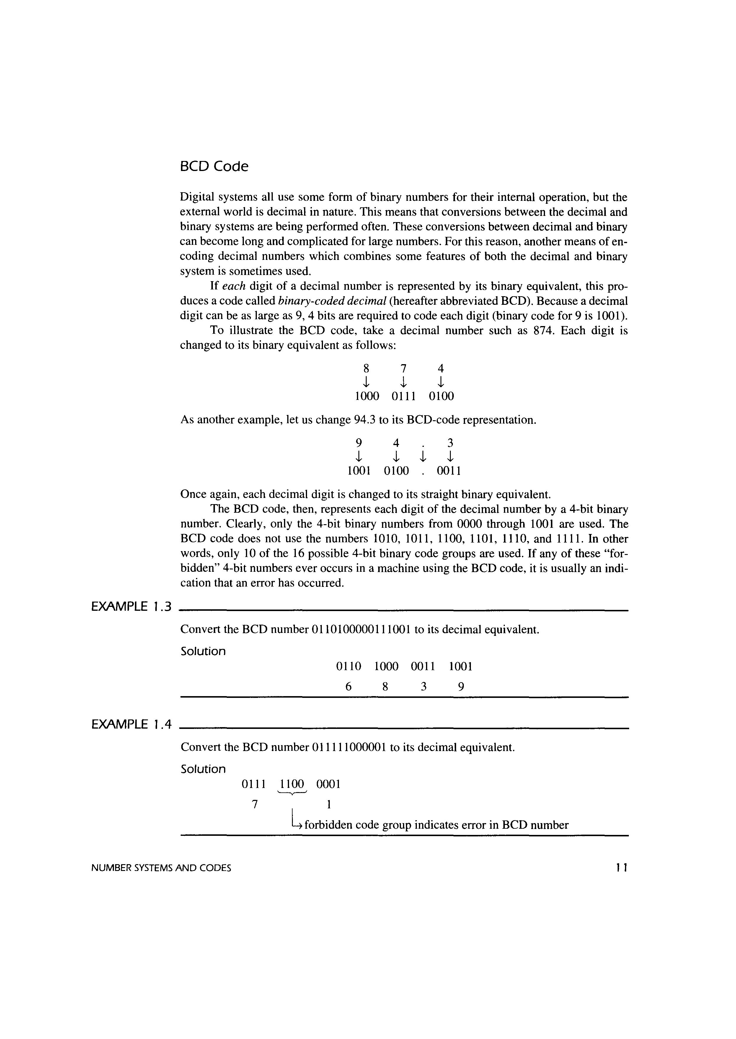
BCD Code
Digital systems all use some form of binary numbers for their internal operation, but the external world is decimal in nature. This means that conversions between the decimal and binary systems are being performed often. These conversions between decimal and binary can become long and complicated for large numbers. For this reason, another means of encoding decimal numbers which combines some features of both the decimal and binary system is sometimes used.
If each digit of a decimal number is represented by its binary equivalent, this produces a code called binary-coded decimal (hereafter abbreviated BCD). Because a decimal digit can be as large as 9, 4 bits are required to code each digit (binary code for 9 is 1001).
To illustrate the BCD code, take a decimal number such as 874. Each digit is changed to its binary equivalent as follows:
8 7 4 j, j, j, 1000 0111 0100
As another example, let us change 94.3 to its BCD-code representation.
9 j, 1001 4 j, j, 0100 3 j, 0011
Once again, each decimal digit is changed to its straight binary equivalent.
The BCD code, then, represents each digit of the decimal number by a 4-bit binary number. Clearly, only the 4-bit binary numbers from 0000 through 1001 are used. The BCD code does not use the numbers 1010, 1011, 1100, 1101, 1110, and 1111. In other words, only 10 of the 16 possible 4-bit binary code groups are used. If any of these "forbidden" 4-bit numbers ever occurs in a machine using the BCD code, it is usually an indication that an error has occurred.
Convert the BCD number 0110100000111001 to its decimal equivalent.
Solution 0110 6 1000 0011 8 3 1001 9
EXAMPLE 1.4
Convert the BCD number 011111000001 to its decimal equivalent.
Solution 0111 7 1100 0001
l forbidden code group indicates error in BCD number
SYSTEMS AND CODES
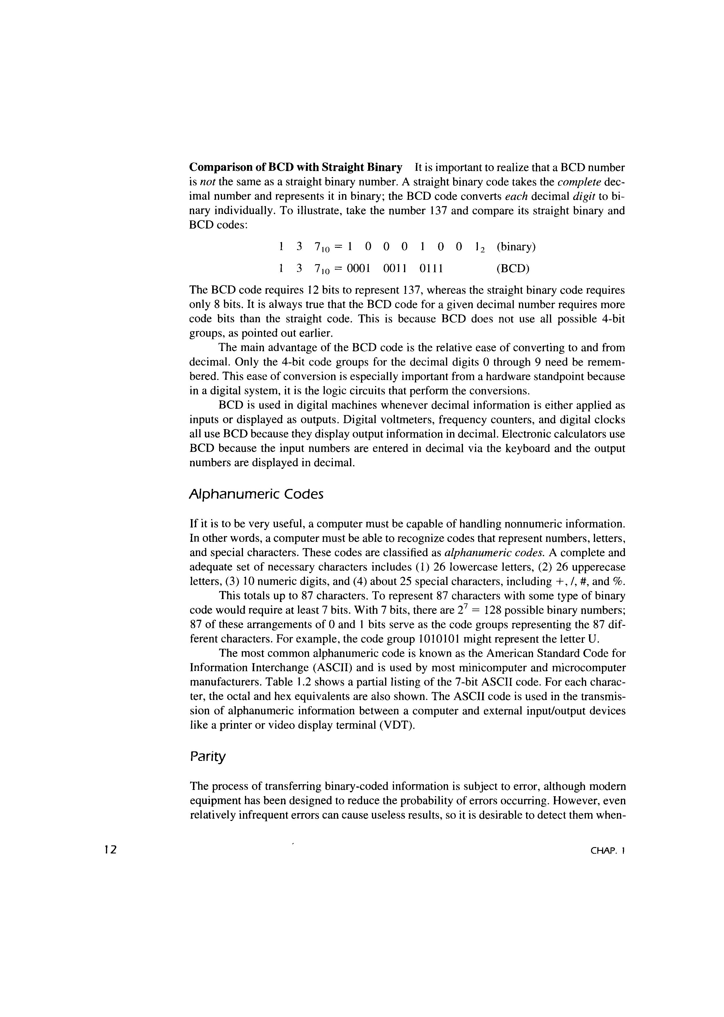
Comparison of BCD with Straight Binary It is important to realize that a BCD number is not the same as a straight binary number. A straight binary code takes the complete decimal number and represents it in binary; the BCD code converts each decimal digit to binary individually. To illustrate, take the number 137 and compare its straight binary and BCD codes:
3 710 = 1 0 0 0 0 0 12 (binary)
3 710 = 0001 0011 0111 (BCD)
The BCD code requires 12 bits to represent 137, whereas the straight binary code requires only 8 bits. It is always true that the BCD code for a given decimal number requires more code bits than the straight code. This is because BCD does not use all possible 4-bit groups, as pointed out earlier.
The main advantage of the BCD code is the relative ease of converting to and from decimal. Only the 4-bit code groups for the decimal digits O through 9 need be remembered. This ease of conversion is especially important from a hardware standpoint because in a digital system, it is the logic circuits that perform the conversions.
BCD is used in digital machines whenever decimal information is either applied as inputs or displayed as outputs. Digital voltmeters, frequency counters, and digital clocks all use BCD because they display output information in decimal. Electronic calculators use BCD because the input numbers are entered in decimal via the keyboard and the output numbers are displayed in decimal.
Alphanumeric Codes
If it is to be very useful, a computer must be capable of handling nonnumeric information. In other words, a computer must be able to recognize codes that represent numbers, letters, and special characters. These codes are classified as alphanumeric codes. A complete and adequate set of necessary characters includes (1) 26 lowercase letters, (2) 26 upperecase letters, (3) 10 numeric digits, and (4) about 25 special characters, including +, /,#,and%.
This totals up to 87 characters. To represent 87 characters with some type of binary code would require at least 7 bits. With 7 bits, there are 27 = 128 possible binary numbers; 87 of these arrangements of O and 1 bits serve as the code groups representing the 87 different characters. For example, the code group 1010101 might represent the letter U.
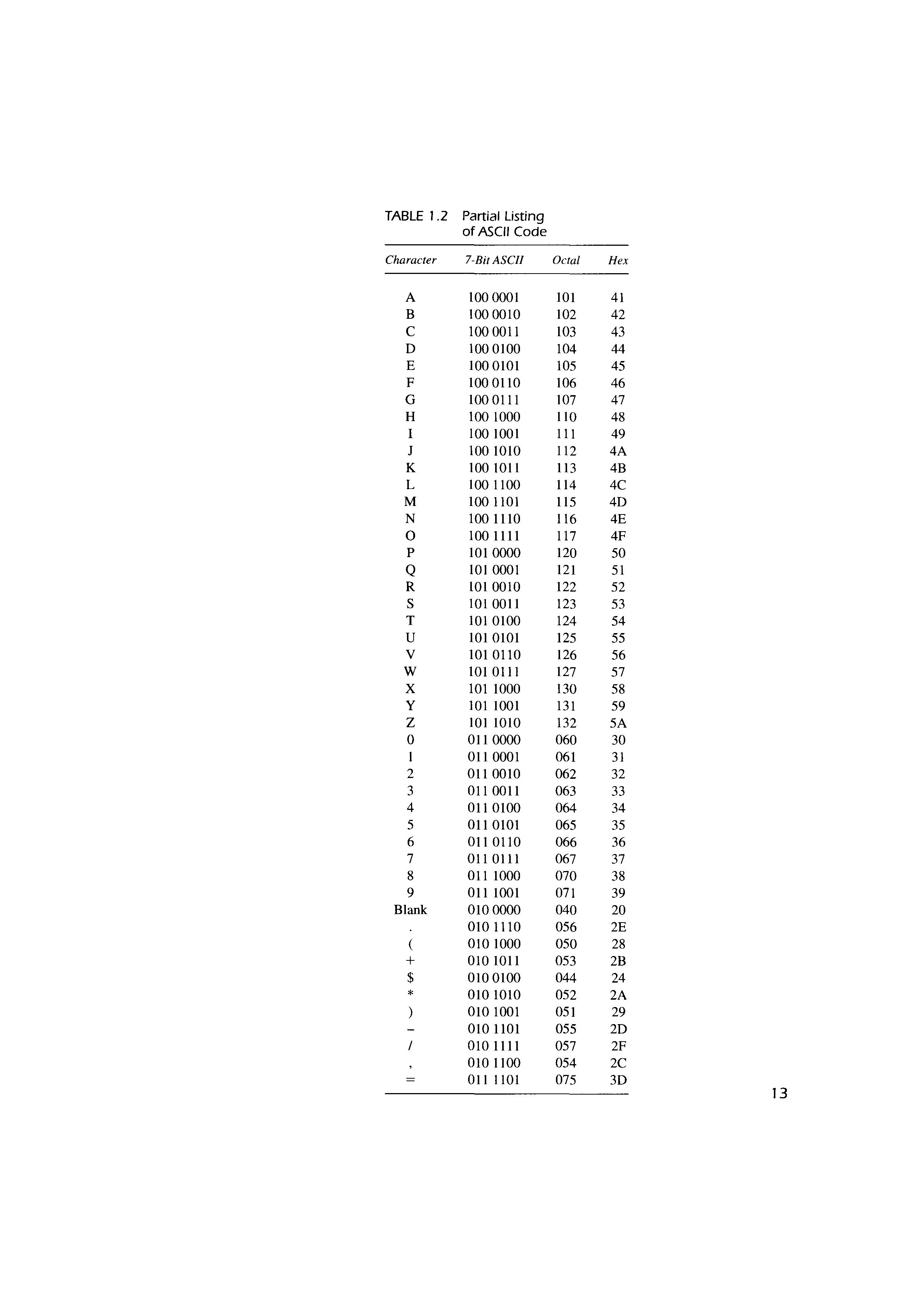
The most common alphanumeric code is known as the American Standard Code for Information Interchange (ASCII) and is used by most minicomputer and microcomputer manufacturers. Table 1.2 shows a partial listing of the 7-bit ASCII code. For each character, the octal and hex equivalents are also shown. The ASCII code is used in the transmission of alphanumeric information between a computer and external input/output devices like a printer or video display terminal (VDT).
Parity
The process of transferring binary-coded information is subject to error, although modem equipment has been designed to reduce the probability of errors occurring. However, even relatively infrequent errors can cause useless results, so it is desirable to detect them when-
TABLE 1.2 Partial Listing of
011 1001 071
010 1011 053 2B
010 0100 044
010 1010 052 2A 010 1001 051
010 1101 055 2D 0101111 057 2F 010 1100 054 2C 011 1101 075 3D
ever possible. One of the most widely used schemes for error detection is the parity method.
A parity bit is an extra bit that is attached to a code group that is being transferred from one location to another. The parity bit is made either O or 1, depending on the number of 1s that are contained in the code group. Two different methods are used.
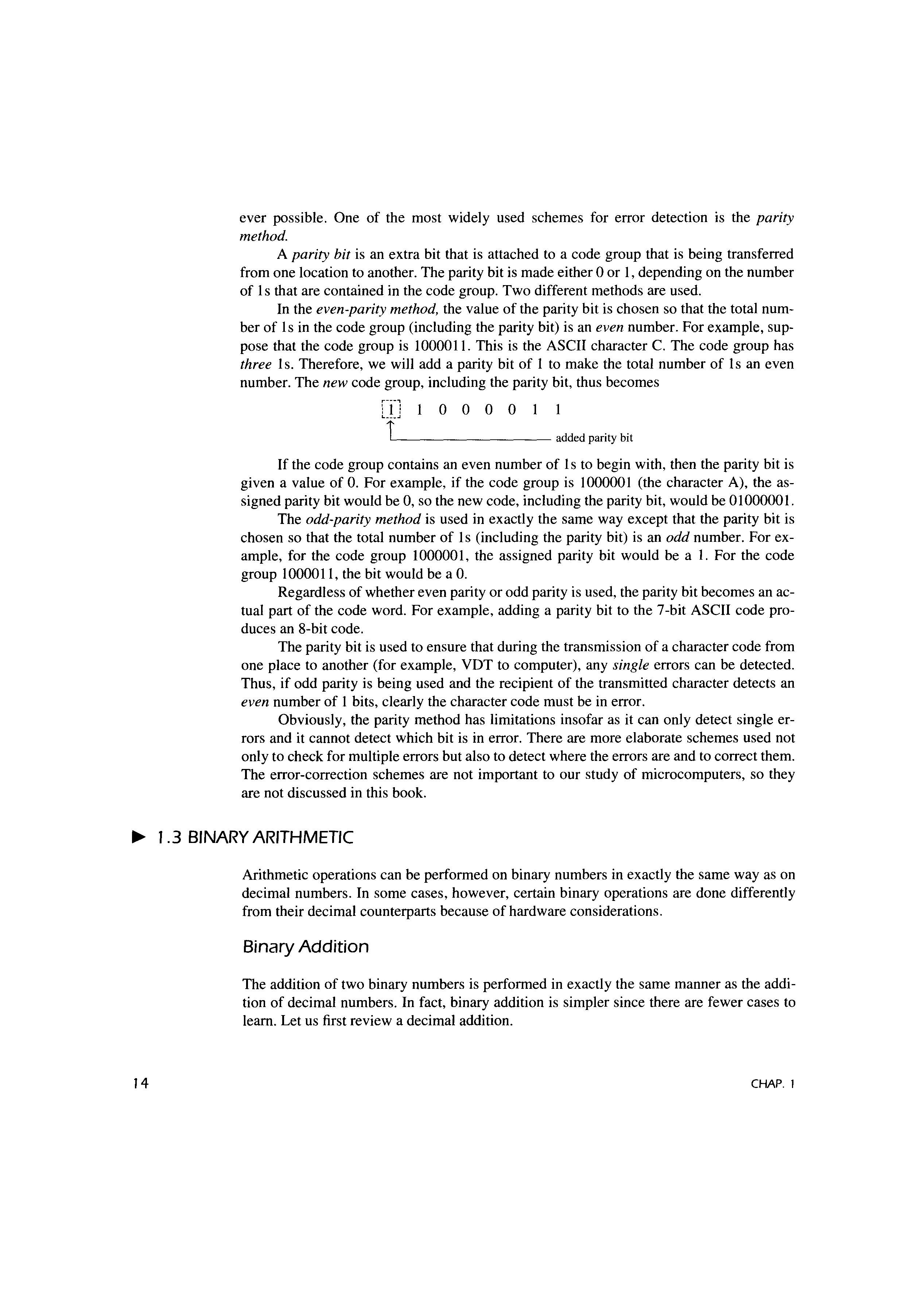
In the even-parity method, the value of the parity bit is chosen so that the total number of ls in the code group (including the parity bit) is an even number. For example, suppose that the code group is 100001 l. This is the ASCII character C. The code group has three ls. Therefore, we will add a parity bit of 1 to make the total number of ls an even number. The new code group, including the parity bit, thus becomes
added parity bit
If the code group contains an even number of ls to begin with, then the parity bit is given a value of 0. For example, if the code group is 1000001 (the character A), the assigned parity bit would be 0, so the new code, including the parity bit, would be 01000001.
The odd-parity method is used in exactly the same way except that the parity bit is chosen so that the total number of ls (including the parity bit) is an odd number. For example, for the code group 1000001, the assigned parity bit would be a 1. For the code group 1000011, the bit would be a 0.
Regardless of whether even parity or odd parity is used, the parity bit becomes an actual part of the code word. For example, adding a parity bit to the 7-bit ASCII code produces an 8-bit code.
The parity bit is used to ensure that during the transmission of a character code from one place to another (for example, VDT to computer), any single errors can be detected. Thus, if odd parity is being used and the recipient of the transmitted character detects an even number of 1 bits, clearly the character code must be in error.
Obviously, the parity method has limitations insofar as it can only detect single errors and it cannot detect which bit is in error. There are more elaborate schemes used not only to check for multiple errors but also to detect where the errors are and to correct them. The error-correction schemes are not important to our study of microcomputers, so they are not discussed in this book
1.3 BINARY ARITHMETIC
Arithmetic operations can be performed on binary numbers in exactly the same way as on decimal numbers. In some cases, however, certain binary operations are done differently from their decimal counterparts because of hardware considerations.
Binary Addition
The addition of two binary numbers is performed in exactly the same manner as the addition of decimal numbers. In fact, binary addition is simpler since there are fewer cases to learn. Let us first review a decimal addition.
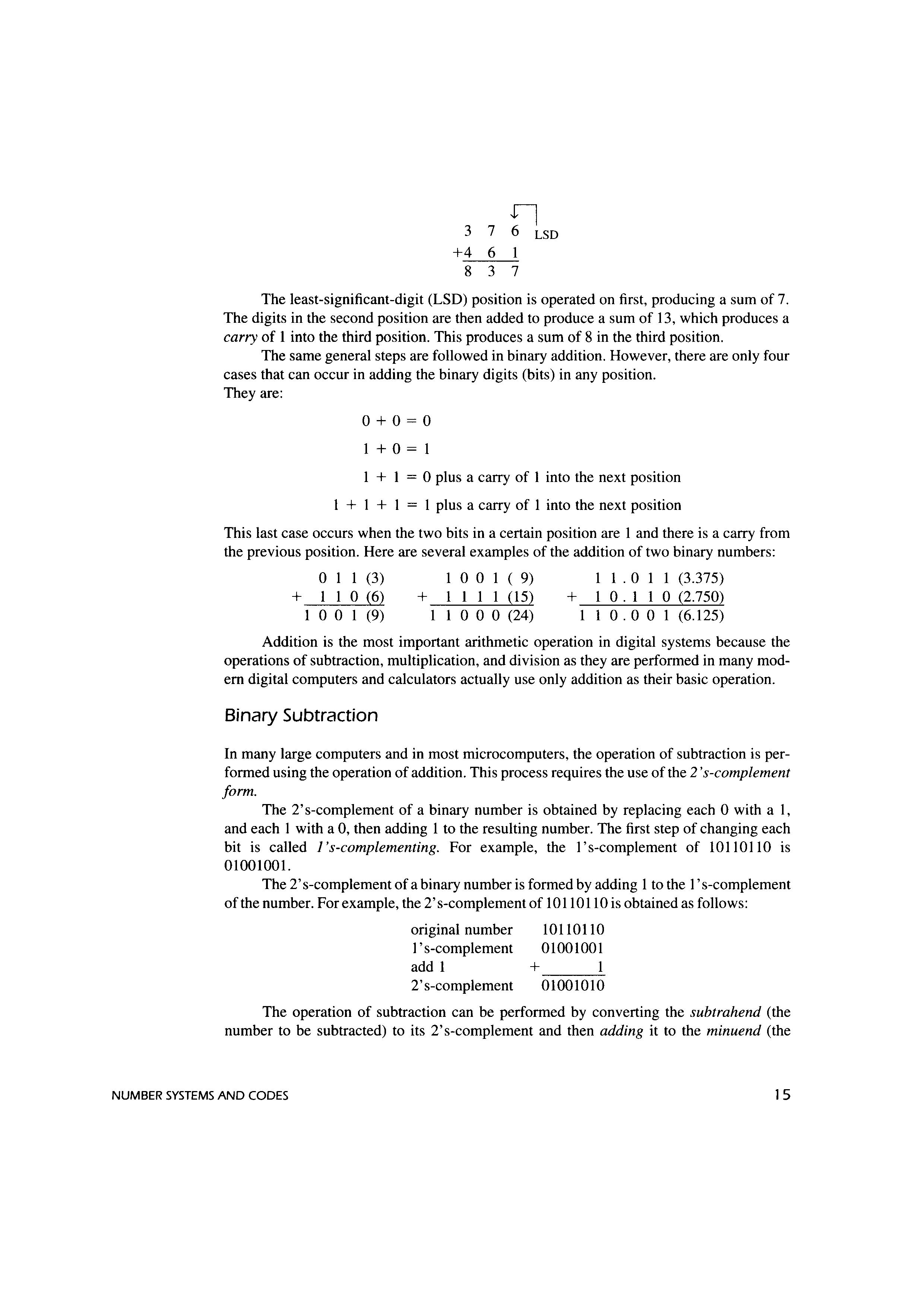
The least-significant-digit (LSD) position is operated on first, producing a sum of 7. The digits in the second position are then added to produce a sum of 13, which produces a carry of 1 into the third position. This produces a sum of 8 in the third position.
The same general steps are followed in binary addition. However, there are only four cases that can occur in adding the binary digits (bits) in any position. They are:
I + 0 = I
+ I = 0 plus a carry of I into the next position
I + I + I = I plus a carry of 1 into the next position
This last case occurs when the two bits in a certain position are I and there is a carry from the previous position. Here are several examples of the addition of two binary numbers:
0 1 1 (3) + 1 1 0 (6)
I O O I (9)
I O O I ( 9) + I 1 1 I (15) I I O O O (24) I I .
Addition is the most important arithmetic operation in digital systems because the operations of subtraction, multiplication, and division as they are performed in many modem digital computers and calculators actually use only addition as their basic operation.
Binary Subtraction
In many large computers and in most microcomputers, the operation of subtraction is performed using the operation of addition. This process requires the use of the 2 's-complement form.
The 2' s-complement of a binary number is obtained by replacing each O with a I, and each I with a 0, then adding 1 to the resulting number. The first step of changing each bit is called J's-complementing. For example, the I's-complement of 10110 I 10 is 01001001.
The 2' s-complement of a binary number is formed by adding 1 to the I's-complement of the number. For example, the 2's-complement of 10110110 is obtained as follows:
original number
I 's-complement add 1
2' s-complement
10110110
01001001 + 1 01001010
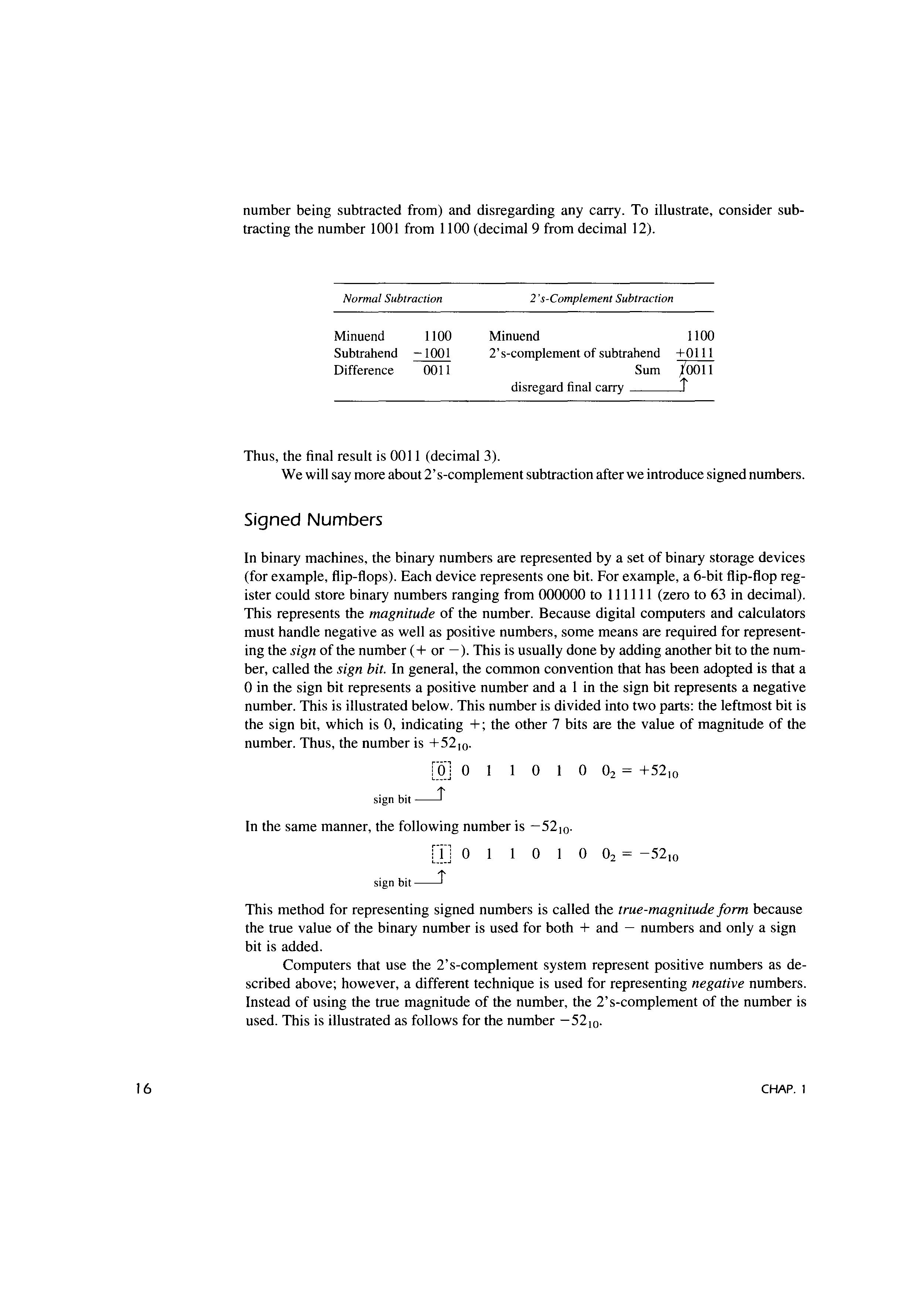
The operation of subtraction can be performed by converting the subtrahend (the number to be subtracted) to its 2's-complement and then adding it to the minuend (the
number being subtracted from) and disregarding any carry. To illustrate, consider subtracting the number 1001 from 1100 (decimal 9 from decimal 12).
Normal Subtraction
Minuend 1100
Subtrahend -1001 Difference 0011
2 's-Complement Subtraction
Minuend 2's-complement of subtrahend Sum 1100 +0111 jo011 disregard final carry --~j
Thus, the final result is 0011 (decimal 3).
We will say more about 2' s-complement subtraction after we introduce signed numbers.
Signed Numbers
In binary machines, the binary numbers are represented by a set of binary storage devices (for example, flip-flops). Each device represents one bit. For example, a 6-bit flip-flop register could store binary numbers ranging from 000000 to 111111 (zero to 63 in decimal). This represents the magnitude of the number. Because digital computers and calculators must handle negative as well as positive numbers, some means are required for representing the sign of the number ( + or - ). This is usually done by adding another bit to the number, called the sign bit. In general, the common convention that has been adopted is that a O in the sign bit represents a positive number and a I in the sign bit represents a negative number. This is illustrated below. This number is divided into two parts: the leftmost bit is the sign bit, which is 0, indicating +; the other 7 bits are the value of magnitude of the number. Thus, the number is +52 10 0
sign bit ___J
In the same manner, the following number is -52 10 [IJ O 0
sign bit__j
This method for representing signed numbers is called the true-magnitude form because the true value of the binary number is used for both + and - numbers and only a sign bit is added.
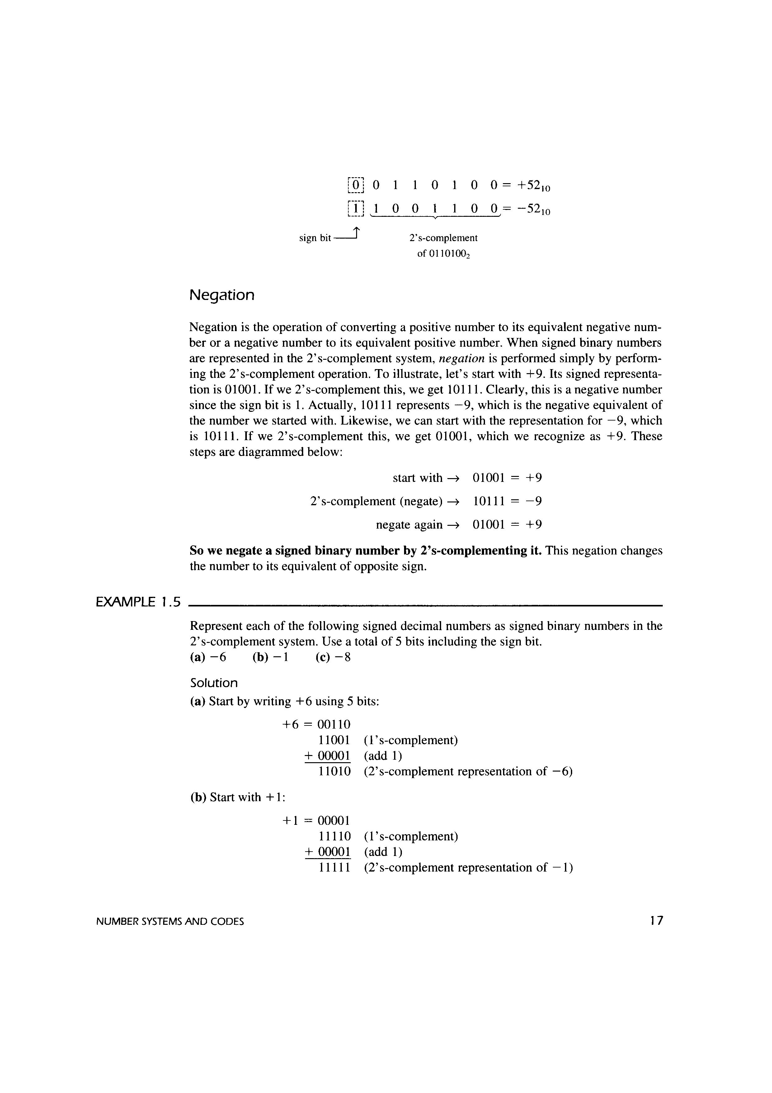
Computers that use the 2's-complement system represent positive numbers as described above; however, a different technique is used for representing negative numbers. Instead of using the true magnitude of the number, the 2's-complement of the number is used. This is illustrated as follows for the number -52 10
EXAMPLE 1.5
sign bit__J
Negation
2's-complement of 01101002
Negation is the operation of converting a positive number to its equivalent negative number or a negative number to its equivalent positive number. When signed binary numbers are represented in the 2's-complement system, negation is performed simply by performing the 2's-complement operation. To illustrate, let's start with +9. Its signed representation is O1001. If we 2' s-complement this, we get 10111. Clearly, this is a negative number since the sign bit is 1. Actually, 10111 represents -9, which is the negative equivalent of the number we started with. Likewise, we can start with the representation for -9, which is 10111. If we 2's-complement this, we get 01001, which we recognize as +9. These steps are diagrammed below:
start with 01001 +9
2's-complement (negate) 10111 -9 negate again~ 01001 = +9
So we negate a signed binary number by 2's-complementing it. This negation changes the number to its equivalent of opposite sign.
Represent each of the following signed decimal numbers as signed binary numbers in the 2's-complement system. Use a total of 5 bits including the sign bit.
(a) -6 (b) -1 (c) -8
Solution
(a) Start by writing +6 using 5 bits:
+6 = 00110
11001 (l's-complement) + 00001 (add 1)
11010 (2's-complement representation of -6)
(b) Start with + 1:
+1 = 00001
11110 (1 's-complement) + 00001 (add 1)
11111 (2's-complement representation of -1)
EXAMPLE 1.6
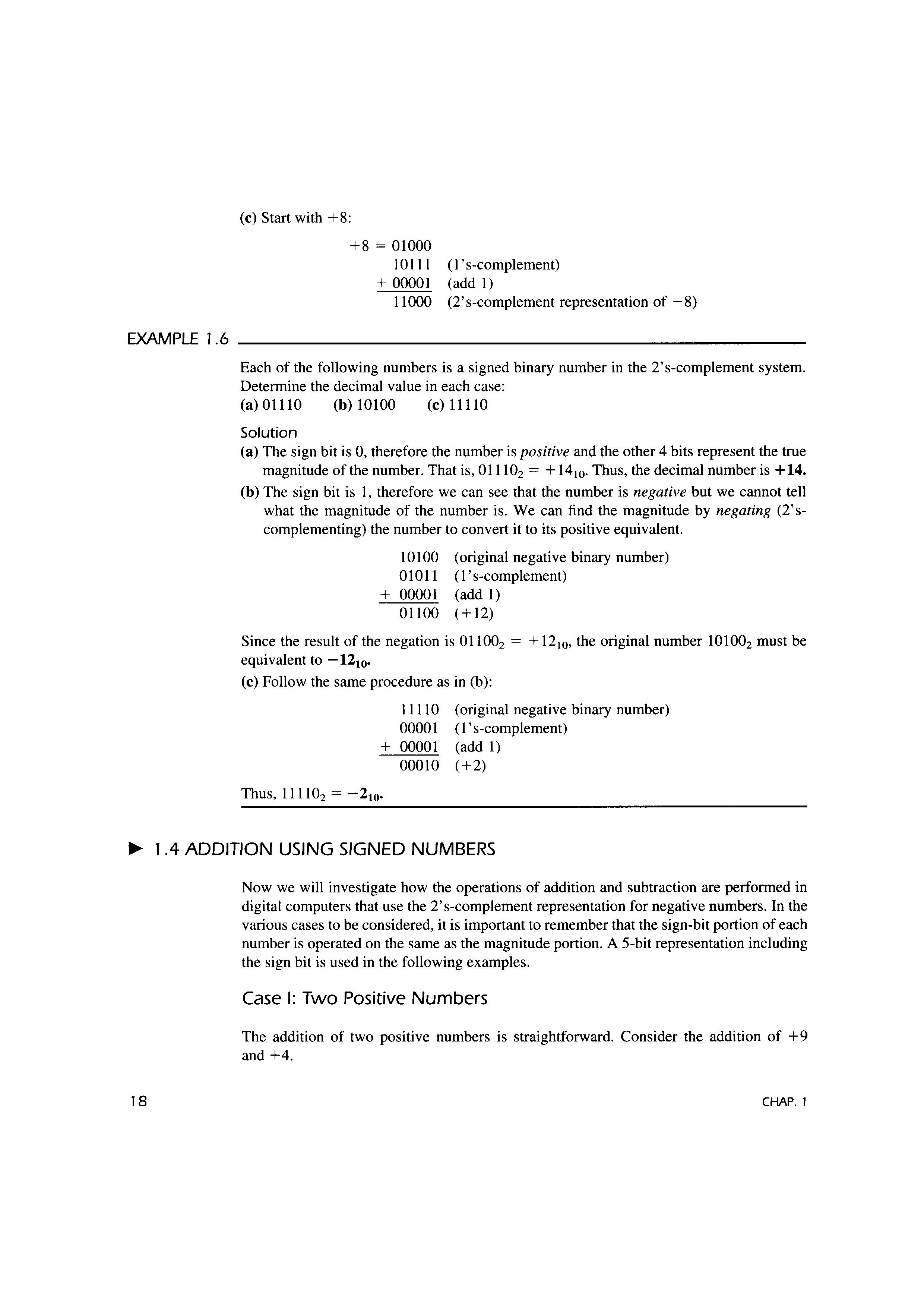
(c) Start with +8:
+8 = 01000
101 I I + 00001 (l's-complement) (add 1)
11000 (2's-complement representation of -8)
Each of the following numbers is a signed binary number in the 2's-complement system. Determine the decimal value in each case: (a) 01110 (b) 10100 (c) 11110
Solution
(a) The sign bit is 0, therefore the number is positive and the other 4 bits represent the true magnitude of the number. That is, 011102 = + 14 10 Thus, the decimal number is + 14.
(b) The sign bit is I, therefore we can see that the number is negative but we cannot tell what the magnitude of the number is. We can find the magnitude by negating (2'scomplementing) the number to convert it to its positive equivalent.
10100 01011 + 00001 01100 (original negative binary number) (l's-complement) (add 1) (+12)
Since the result of the negation is 011002 = + 12 10, the original number 101002 must be equivalent to -12 10•
(c) Follow the same procedure as in (b):
I I I 10 (original negative binary number) 00001 (l's-complement) + 00001 (add 1) 00010 (+2)
Thus, 1 I I 102 = -2 10•
I .4 ADDITION USING SIGNED NUMBERS
Now we will investigate how the operations of addition and subtraction are performed in digital computers that use the 2's-complement representation for negative numbers. In the various cases to be considered, it is important to remember that the sign-bit portion of each number is operated on the same as the magnitude portion. A 5-bit representation including the sign bit is used in the following examples.
Case I: Two Positive Numbers
The addition of two positive numbers is straightforward. Consider the addition of +9 and +4.
CHAP. I